-
Troubleshooting the code
02/02/2022 at 21:55 • 0 commentsMy Roomba632 class kinda works but still has some issues:
- Roomba doesn't respond to commands reliably;
- Reading datastream fails;
These are the 2 things it was designed for, but I refuse to call it a failure. It's a "work in progress".
One of the problems with troubleshooting and debugging is the lack of feedback. Sending a command works, or doesn't work. But I can't see where the code breaks down.
Does the request for a datastream actually start a datastream? Or does my interpretation of the data fail?
Luckily I have a separate ESP8266 set up on a breadboard. I can connect this to the computer and use the computer as a stand-in for the roomba.
This gave me some AHaH!-moments. Most of them already taken care of in the previously posted code. For instance:
- A waaaay to complicated state machine with too many copies of mostly the same code. Transition changes are now in their own function;
- Because of all the copies, I didn't notice I was sending the same opcode for all commands. Big DOH!;
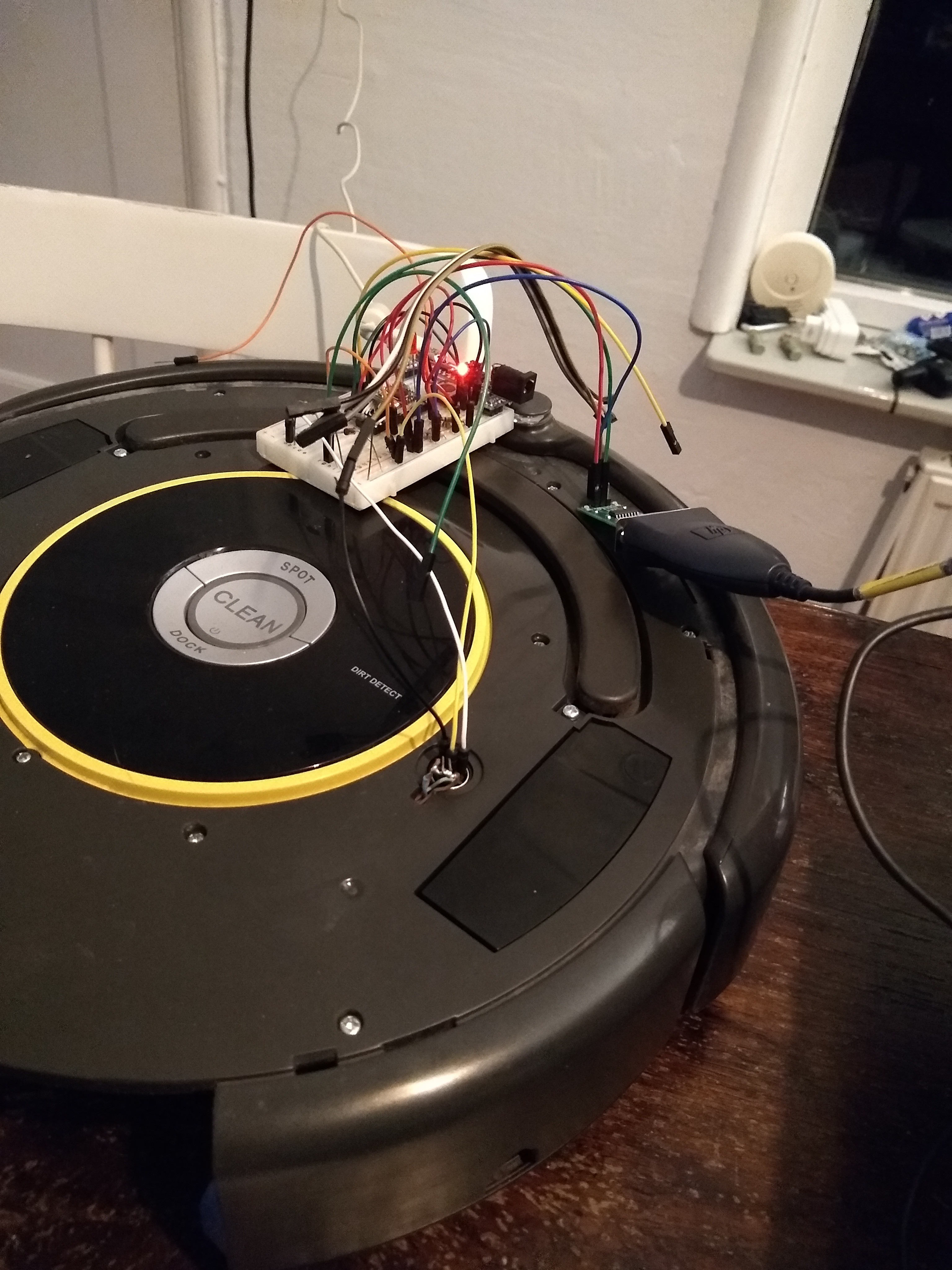
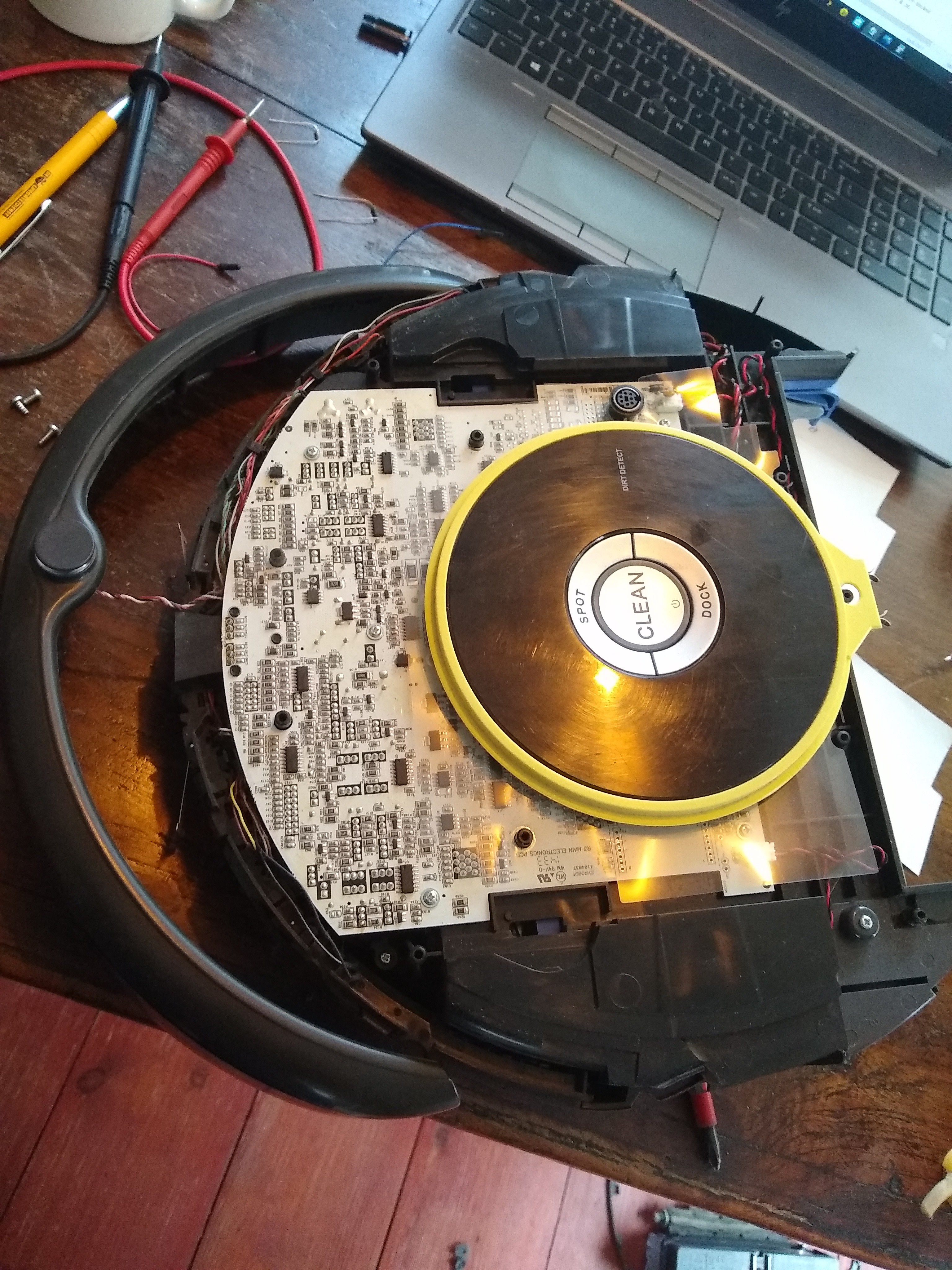
When I was confident I was sending out the proper commands in the proper order I connected the roomba for even MORE troubleshooting:
![]()
First I connected the roomba on it's own to the computer to check its responses to the commands I had lined up.
Then I connected the breadboard-ESP8266 to the Rx of the roomba and the Tx of the roomba to the computer. This way I could check if the datastream would start and stop on command.
And then I had my second round of AhAH!-moments:
Datastream:
I was expecting something with a header of '19' then '16' for the number of databytes, 16 databytes and a byte for the checksum at the end.
What I got was:
19 26 15 0 22 62 159 23 254 246 24 27 25 10 129 26 10 136 35 2 37 0 43 0 5 44 0 2 155
19 26 15 0 22 62 159 23 254 246 24 27 25 10 129 26 10 136 35 2 37 0 43 0 5 44 0 2 155
19 26 15 0 22 62 159 23 254 246 24 27 25 10 129 26 10 136 35 2 37 0 43 0 5 44 0 2 155
19 26 15 0 22 62 159 23 254 246 24 27 25 10 129 26 10 136 35 2 37 0 43 0 5 44 0 2 155
19 26 15 0 22 62 159 23 254 246 24 27 25 10 129 26 10 136 35 2 37 0 43 0 5 44 0 2 155
Why 26 bytes?? Rereading the docs closely makes me feel stoopid, again! The ID's are also sent with the datastream preceding the databytes. So above stream translates to:
[19] Message header
[26] Number of total bytes before checksum
[15] Packet ID for "dirt detect"
[0] Databyte for "dirt detec". No dirt detected.
[22] Packet ID for "battery voltage"
[62] Most significant data byte for "battery voltage"
[159] Least significant data byte for "battery voltage"
*
*
[44] Packet ID for "Wheel encoder counts right"
[0] Most significant data byte for "Wheel encoder counts right"
[2] Least significant data byte for "Wheel encoder counts right"
[155] Checksum.
All bytes including header and checksum added together without rollover, gives 0;
Timing:
This setup also showed me I need a short delay after sending a "start" and after a "set mode" command.
I can't find any documentation on these delays, but the 20ms seems to work fine.
More more troubleshooting:
The ESP8266 only has 1 serial port. To get more feedback from the code I sprinkled some commands to set variables that I can request through MQTT. This way I can check which state the code reaches and what bytes it receives.
Apparently It only receives 1 byte, which seems a bit random.
It appears to be only the last byte of a stream because all the previous bytes are handled and discarded. And after much thinking I came to the conclusion it was the "Wake up" message that was handled... The datastream isn't starting for some reason.
Back to the breadboard and upload the code to see if the command to start the stream is handled correctly. And it wasn't! So the problem is manageable!
I made a mistake when putting in another state in the state machine to send the command to start the stream with a delay. I never transitioned from that state because I forgot to set it like this:
datastreamState = datastreamStarting;
Instead it was set to it's own case by:
datastreamState = datastreamSetMode;
So .. problem found??
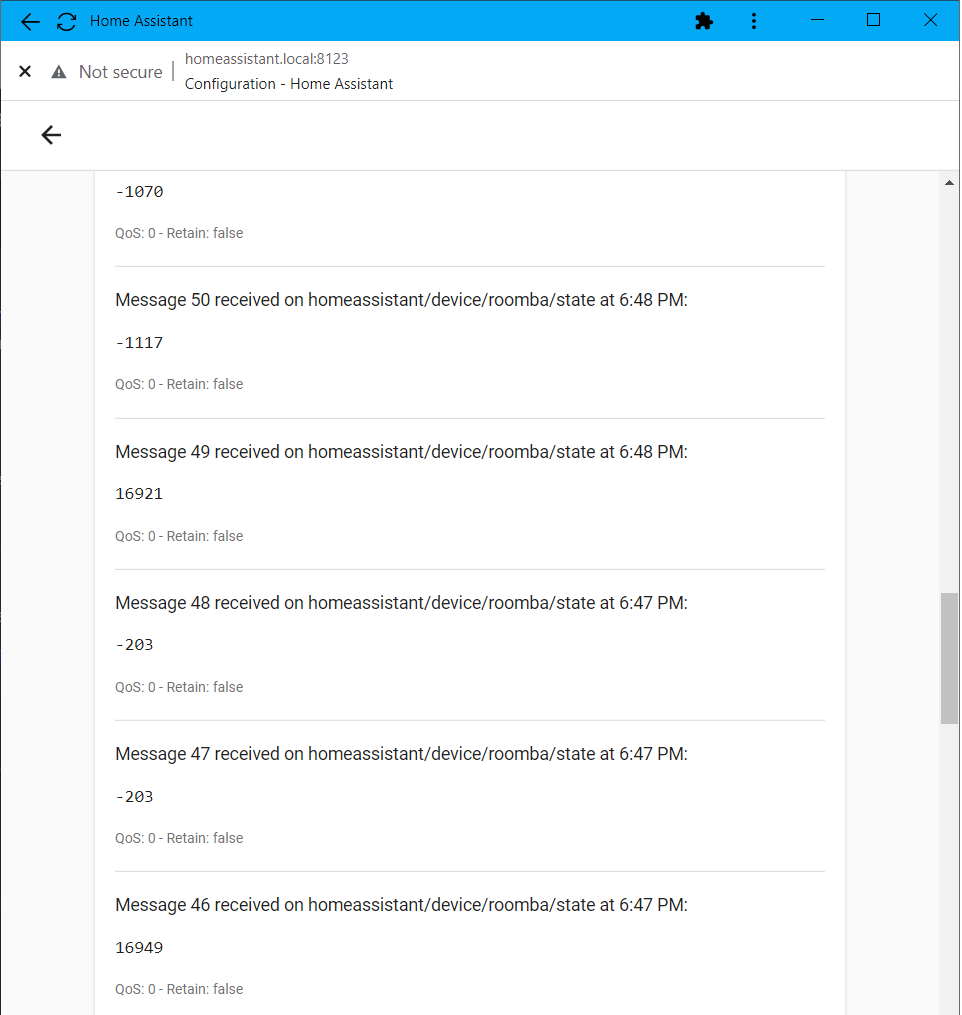
I checked by manually feeding some dummy streamdata I captured earlier from the roomba to the breadboard setup. This worked! So feeling confident I uploaded the new code to the roomba setup and BEHOLD!!!
![]()
What we see here is messages with the actual battery voltage: 16.949V and current -203mA draw when Idle to -1117mA when cleaning.
These values update about 60 times / second on the ESP8266. From there I can combine them with sensordata from the IMU for instance or use it to make world peace.
I will call this a succes and upload the library I have so far.
Next up: changing the power configuration and adding the IMU somewhere in the roomba.
-
Classy Roomba632
01/30/2022 at 19:49 • 0 commentsWell! I learned a lot these days :)
The first version of the library / class seems so work and seems stable. It's still a work in progress. I will upload a zip if it's nearer to complete.
For now it can put the roomba in diferent states by sending commands without delays. It can request and interpret a datastream (with checksum!) and make the data accesable for further processing.
All "commands" are received as "requests" and handled according to set priority in state machines. The states are strictly controlled. For instance: When "cleaning" it's useless to send another cleaning command.
Header:
#ifndef ROOMBA632_H
#define ROOMBA632_H

// Arduino versioning.
#include "Arduino.h"

enum OImodes {
    Off = 0,
    Passive = 1,
    Safe = 2,
    Full = 3
};

enum states {
    roombaIdle,
    roombaCharging,
    roombaCleaning,
    roombaSpotCleaning,
    roombaDocking,
    roombaDriving,
    roombaMusic
};

enum receivedDatastreamStates {
    datastreamIdle,
    datastreamStarting,
    datastreamWaitingForHeader,
    datastreamWaitingForNbytes,
    datastreamReadingData,
    datastreamCheckingData,
    datastreamStopping,
};

enum sendingCommandStates {
    sendingCommandsIdle,
    sendingCommandsSetMode,
    sendingCommandsSending,
};
enum commandStates{
    startIO,
    setMode,
    sendCommand
};

enum opcodes{
    OCstart = 128,
    OCSafemode = 131,
    OCFullmode = 132,
    OCSpot = 134,
    OCClean = 135,
    OCDrive = 137,
    OCLeds = 139,
    OCSong = 140,
    OCPlaySong = 141,
    OCDatastream = 148,
    OCPauseDatastream = 150,
    OCDock = 143,
    OCStop = 173
};

class Roomba632 {
public:
    Roomba632();
    void handler();
    //Set a flag (and variables) as a "request" witch is handled in order of priority:
    void stop();
    void clean();
    void spot();
    void dock();
    void startDatastream();
    void stopDatastream();
    void playMusic();
    void drive();

    //Privately set public variables
    uint8_t dirtDetect;
    uint16_t batteryVoltage;
    int16_t current;
    int8_t batteryTemp;
    uint16_t batteryCharge;
    uint16_t batteryCapacity;
    uint8_t OImode; //enum for states
    uint8_t songPlaying;
    int16_t encoderLeft;
    int16_t encoderRight;
    int16_t angle; //calculated from encoders
    int8_t distance; //calculated from encoders

    //Privately set public states. Only set and change states from within state machine.
    int state; //enum for states
    //int receivingDatastreamState = datastreamIdle; //enum for states
    //int sendingCommands = sendingCommandsIdle; //enum for states

    //Privately set public flags
    volatile bool dataReady;
    volatile bool charging;
    volatile bool b_songPlaying;
    volatile bool b_dirtDetected;
    volatile bool sensorTripped; //for bump cliff and wheel drop sensors

private:
    //unsigned long _songLength(song as argument); //song
    void SendStopCommand();
    void SendCleanCommand();
    void SendDockCommand();
    void SendSpotCommand();
    void SendPlayMusicCommand();
    void _evilLights();
    //Private flags
    volatile bool p_cleanFlag;
    volatile bool p_dockFlag;
    volatile bool p_spotFlag;
    volatile bool p_stopFlag;
    volatile bool p_requestStopDatastreamFlag;
    volatile bool p_requestStartDatastreamFlag;
    volatile bool p_playMusicFlag;
    volatile bool p_driveFlag;

    //Private counters and timers
    uint8_t p_musicCounter; //could be static?
    unsigned long p_musicTimer; //could be static?

};

#endif
And source:
// Roomba632.cpp
// By Simon Jansen 2021-01-29 "the pandemic times"

#include "Roomba632.h"

#define DATASTREAMTIMEOUT 1000
#define DATASTREAMMAXERROR 3
#define COMMANDSTARTTIMEOUT 20
#define COMMANDMODETIMEOUT 20
#define COMMANDTIMEOUT 20

Roomba632::Roomba632(){
    //Publicaly set variables
    //music song to be played
    //driving instructions

    //Privately set public variables
    batteryVoltage = 0;
    current = 0;
    batteryTemp = 0;
    batteryCharge = 0;
    batteryCapacity = 0;
    OImode = 0; //enum for states
    encoderLeft = 0;
    encoderRight = 0;
    angle = 0; //calculated from encoders
    distance = 0; //calculated from encoders

    //Privately set public states. Only set and change states from within state machine.
    state = roombaIdle; //enum for states
    //p_requestStartDatastreamFlag = false;
    //int receivingDatastreamState = datastreamIdle; //enum for states
    //int sendingCommands = sendingCommandsIdle; //enum for states

    //Privately set public flags
    dataReady = false;
    charging = false;
    b_songPlaying = false;
    b_dirtDetected = false;
    sensorTripped = false; //for bump cliff and wheel drop sensors

    //Private flags
    p_cleanFlag = false;
    p_dockFlag = false;
    p_spotFlag = false;
    p_stopFlag = false;
    p_requestStartDatastreamFlag = false;
    p_requestStopDatastreamFlag = false;
    p_playMusicFlag = false;
    p_driveFlag = false;

    //Private counters and timers
    p_musicCounter = 0; //could be static?
    p_musicTimer = 0; //could be static?

    //Initialize serial connection to Roomba
    Serial.begin(115200);
}

//public functions for change in state set a flag (and vairables) as a 'request' whitch is handled in order of prirority
void Roomba632::stop(){
    p_stopFlag = true;
}
void Roomba632::clean(){
    p_cleanFlag = true;
}
void Roomba632::spot(){
    p_spotFlag = true;
}
void Roomba632::dock(){
    p_dockFlag = true;
}
void Roomba632::startDatastream(){
    p_requestStartDatastreamFlag = true;
}
void Roomba632::stopDatastream(){
    p_requestStopDatastreamFlag = true;
}
/*
void Roomba632::playMusic(arguments){
    //set music to be played
    p_playMusicFlag = true;
}
void Roomba632::drive(arguments){
    //set driving variables
    p_driveFlag = true;
}
*/

void Roomba632::handler(){
    //state machine for high level states
    switch (state){
        case roombaCharging: //Charging
                    //Check charging flag
            if (!charging){ //Roomba wandered off!
                //start datastream to figure out what it's up to
            }
        break;
        case roombaIdle: //IDLE: not charging, driving, playing music or cleaning
            p_stopFlag = false; //Clear stop request flag if set
            //Keep alive
            //Check flags in appropriate order of prirority
            if(p_cleanFlag){
                SendCleanCommand();
            }
            else if(p_spotFlag){
                SendSpotCommand();
            }
            else if(p_dockFlag){
                SendDockCommand();
            }
            else if(p_playMusicFlag){
                SendPlayMusicCommand();
            }
            break;
            /*
            else if(p_driveFlag){
                Serial.write(OCstart);
                Serial.write(OCSafemode);
                Serial.write(OCSpot);
                state = roombaCleaning;
            }
            */
        case roombaCleaning:
            p_cleanFlag = false; //clear request flag
            if(p_stopFlag){
                SendStopCommand();
            }
            else if(p_dockFlag){
                SendDockCommand();
            }
            else if(p_spotFlag){
                SendSpotCommand();
            }
            else if(p_playMusicFlag){
                SendPlayMusicCommand();
            }
            break;
        case roombaSpotCleaning:
            p_spotFlag = false; //clear request flag
            if(p_stopFlag){
                SendStopCommand();
            }
            else if(p_cleanFlag){
                SendCleanCommand();
            }
            else if(p_dockFlag){
                SendDockCommand();
            }
            else if(p_playMusicFlag){
                SendPlayMusicCommand();
            }
            break;
        case roombaDocking:
            p_dockFlag = false; //clear request flag
            if(p_stopFlag){
                SendStopCommand();
            }
            else if(p_cleanFlag){
                SendCleanCommand();
            }
            else if(p_spotFlag){
                SendSpotCommand();
            }
            else if(p_playMusicFlag){
                SendPlayMusicCommand();
            }
            break;
        case roombaDriving:
            p_driveFlag = false;
            state = roombaIdle;
            break;
        case roombaMusic:
            p_playMusicFlag = false;
            //time music or poll state
            state = roombaIdle;
            break;
    }

    //state machine for handling datastream
    static int datastreamState; //should be initialized to 0 thus Idle state wich is also default
    static unsigned long commandTimer;
    static unsigned long timeouttimer;
    static byte databuffer[26];
    static char i, errorCounter;
    static byte checksum;
    switch (datastreamState){
        case datastreamIdle: //datastreamIdle, 0, IDLE
            p_requestStopDatastreamFlag = false;
            if (p_requestStartDatastreamFlag){
                Serial.write(OCstart); //Roomba will change to passive mode
                //maybe clear data?
                datastreamState = datastreamStarting;
                commandTimer = millis() + COMMANDSTARTTIMEOUT;
            }
            //Check for charging message

            break;
        case datastreamStarting:
            if (millis() > commandTimer){
                //setup datastream
                Serial.write(OCSafemode);
                Serial.write(OCDatastream); //start stream
                Serial.write(10); //10 packets
                Serial.write(15); //1- dirt detect U 1
                Serial.write(22); //2- voltage U 2
                Serial.write(23); //3- current S 2
                Serial.write(24); //4- Battery temp S 1
                Serial.write(25); //5- Battery charge U 2
                Serial.write(26); //6- Battery capacity U 2
                Serial.write(35); //7- OI mode U 1
                Serial.write(37); //8- Song playing? U 1
                Serial.write(43); //9- Wheel encoder counts left S 2
                Serial.write(44); //10-Wheel encoder counts right S 2
                //serial write startDatastream
                datastreamState = datastreamWaitingForHeader;
                //Set timer
                timeouttimer = millis() + DATASTREAMTIMEOUT;
            }
            break;
        case datastreamWaitingForHeader:
            p_requestStartDatastreamFlag = false;
            if (p_requestStopDatastreamFlag){
                datastreamState = datastreamStopping;
            }
            //check for charging message
            //set charging flag
            //charging = true;
            //reset charging flag
            //charging = false;

            //disentangle datastream and do checksum for valid data.
            if (Serial.available()){
                if(Serial.read()==19){ //Header for datastream
                    datastreamState = datastreamWaitingForNbytes;
                    timeouttimer = millis() + DATASTREAMTIMEOUT; //reset timer
                }
                //timeout
                else if (millis() > timeouttimer){
                    datastreamState = datastreamIdle;
                    errorCounter++;
                    if (errorCounter == DATASTREAMMAXERROR){
                        p_requestStopDatastreamFlag = true;
                        datastreamState = datastreamStopping;
                        errorCounter = 0;
                    }
                }
            }
            break;
        case datastreamWaitingForNbytes:
            if (Serial.available()){
                if(Serial.read()== 26){ //number of bytes
                    datastreamState = datastreamReadingData;
                    i = 0;
                    checksum = 45; //19 + 26
                    timeouttimer = millis() + DATASTREAMTIMEOUT; //reset timer
                }
                else{
                    errorCounter++;
                    if (errorCounter == DATASTREAMMAXERROR){
                        p_requestStopDatastreamFlag = true;
                        datastreamState = datastreamStopping;
                        errorCounter = 0;
                    }
                }
            }
            //timeout
            if (millis() > timeouttimer){
                datastreamState = datastreamIdle;
                errorCounter++;
                if (errorCounter == DATASTREAMMAXERROR){
                    p_requestStopDatastreamFlag = true;
                    datastreamState = datastreamStopping;
                    errorCounter = 0;
                }
            }
            break;
        case datastreamReadingData:
            if(Serial.available()){
                databuffer[i] = Serial.read();
                checksum += databuffer[i];
                if(i==25){
                    datastreamState = datastreamCheckingData;
                    timeouttimer = millis() + DATASTREAMTIMEOUT; //Reset timer
                }
                i++;
            }
            //timeout
            else if (millis() > timeouttimer){
                datastreamState = datastreamIdle;
                errorCounter++;
                if (errorCounter == DATASTREAMMAXERROR){
                    p_requestStopDatastreamFlag = true;
                    datastreamState = datastreamStopping;
                    errorCounter = 0;
                }
            }
            break;
        case datastreamCheckingData:
            if(Serial.available()){
                checksum += Serial.read(); //Addition to checksum should give 256 on rollover of byte 0
                if (checksum == 0){
                    //checksum passed
                    dirtDetect = databuffer[1];
                    batteryVoltage = (databuffer[3] << 8) | databuffer[4];
                    current = (databuffer[6] << 8) | databuffer[7];
                    batteryTemp = databuffer[9];
                    batteryCharge = (databuffer[11] << 8) | databuffer[12];
                    batteryCapacity = (databuffer[14] << 8) | databuffer[15];
                    OImode = databuffer[17];
                    songPlaying = databuffer[19];
                    encoderLeft = (databuffer[21] << 8) | databuffer[22];
                    encoderRight = (databuffer[24] << 8) | databuffer[25];
                    dataReady = true;
                }
                else{
                    //checksum failed
                    errorCounter++;
                    if (errorCounter == DATASTREAMMAXERROR){
                        p_requestStopDatastreamFlag = true;
                        datastreamState = datastreamStopping;
                        errorCounter = 0;
                    }
                }
                datastreamState = datastreamWaitingForHeader;
            }
            //timeout
            else if (millis() > timeouttimer){
                datastreamState = datastreamIdle;
                errorCounter++;
                if (errorCounter == DATASTREAMMAXERROR){
                    p_requestStopDatastreamFlag = true;
                    datastreamState = datastreamStopping;
                    errorCounter = 0;
                }
            }
            break;
        case datastreamStopping:
            //handle last message
            //serial write stop datastream
            Serial.write(OCPauseDatastream);
            Serial.write(0);
            datastreamState = datastreamIdle;
            break;
    }

}
void Roomba632::SendStopCommand(){
    Serial.write(OCStop);
    state = roombaIdle;
}
void Roomba632::SendCleanCommand(){
    static int commandstate;
    static unsigned long commandTimer;
    switch (commandstate){
        case startIO:
            Serial.write(OCstart);
            commandstate = setMode;
            commandTimer = millis() + COMMANDSTARTTIMEOUT;
            break;
        case setMode:
            if (millis() > commandTimer){
                Serial.write(OCSafemode);
                commandstate = sendCommand;
                commandTimer = millis() + COMMANDMODETIMEOUT;
            }
            break;
        case sendCommand:
            if (millis() > commandTimer){
                Serial.write(OCClean);
                commandstate = startIO; //reset state
                state = roombaCleaning;
            }
            break;
    }
}

void Roomba632::SendDockCommand(){
    static int commandstate;
    static unsigned long commandTimer;
    switch (commandstate){
        case startIO:
            Serial.write(OCstart);
            commandstate = setMode;
            commandTimer = millis() + COMMANDSTARTTIMEOUT;
            break;
        case setMode:
            if (millis() > commandTimer){
                Serial.write(OCSafemode);
                commandstate = sendCommand;
                commandTimer = millis() + COMMANDMODETIMEOUT;
            }
            break;
        case sendCommand:
            if (millis() > commandTimer){
                Serial.write(OCDock);
                commandstate = startIO; //reset state
                state = roombaDocking;
            }
            break;
    }
}

void Roomba632::SendSpotCommand(){
    static int commandstate;
    static unsigned long commandTimer;
    switch (commandstate){
        case startIO:
            Serial.write(OCstart);
            commandstate = setMode;
            commandTimer = millis() + COMMANDSTARTTIMEOUT;
            break;
        case setMode:
            if (millis() > commandTimer){
                Serial.write(OCSafemode);
                commandstate = sendCommand;
                commandTimer = millis() + COMMANDMODETIMEOUT;
            }
            break;
        case sendCommand:
            if (millis() > commandTimer){
                Serial.write(OCSpot);
                commandstate = startIO; //reset state
                state = roombaSpotCleaning;
            }
            break;
    }
}
void Roomba632::SendPlayMusicCommand(){
    static int commandstate;
    static unsigned long commandTimer;
    switch (commandstate){
        case startIO:
            Serial.write(OCstart);
            commandstate = setMode;
            commandTimer = millis() + COMMANDSTARTTIMEOUT;
            break;
        case setMode:
            if (millis() > commandTimer){
                Serial.write(OCFullmode);
                commandstate = startIO; //reset state
                state = roombaMusic; //sending music commands is handled in the music state
            }
            break;
    }
}
void Roomba632::_evilLights(){

}

/*
unsigned long Roomba632::_songLength(song as argument){
    return songlength;
}
*/
Troubleshooting:
I added timers to the functions that send the commands. The roomba apparently needs some time to process it all (brain the size of a universe and all we ask it to do is to suck up dust) The commands for cleaning, docking, spot etc. work quite nicely like this.
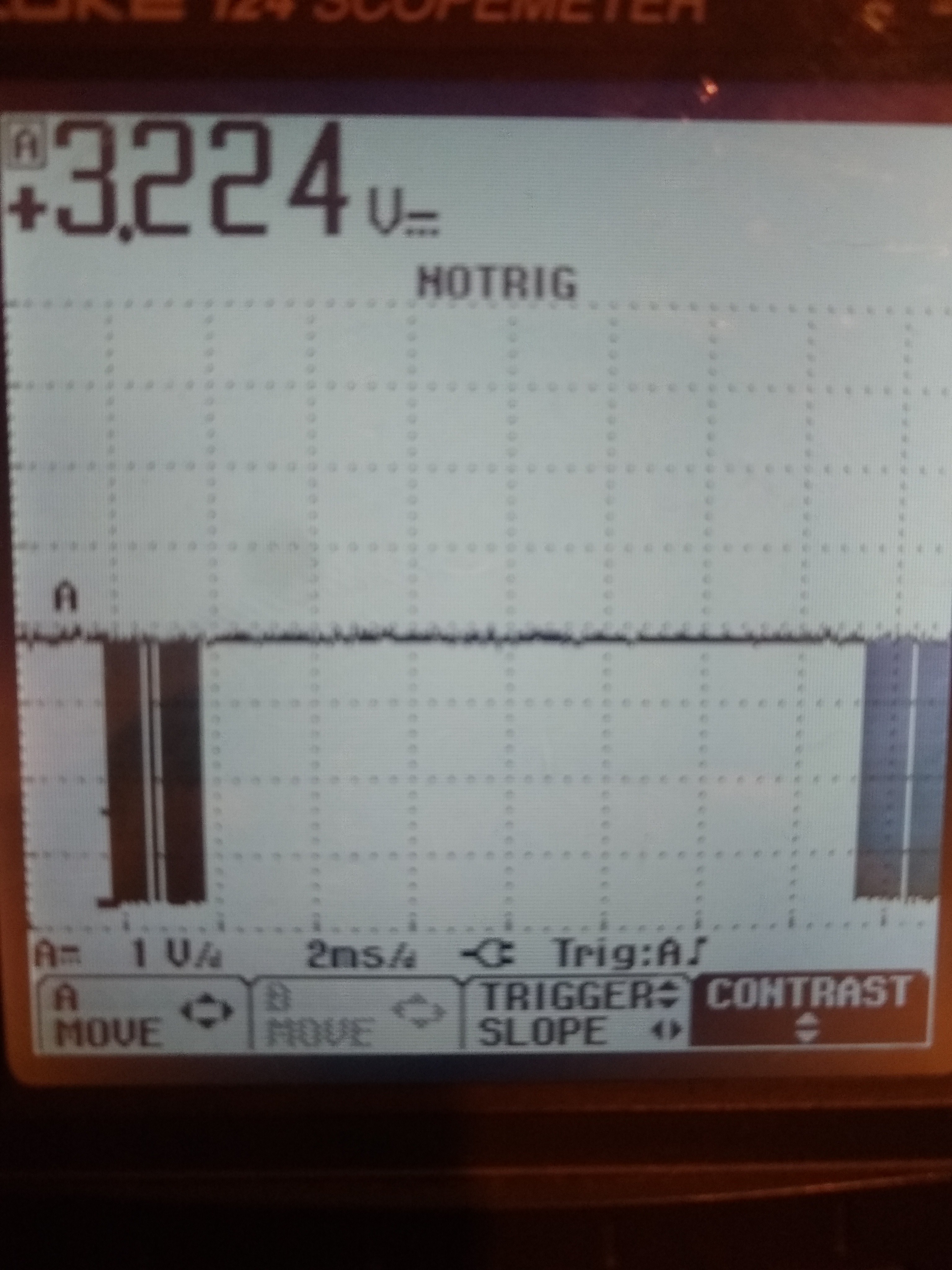
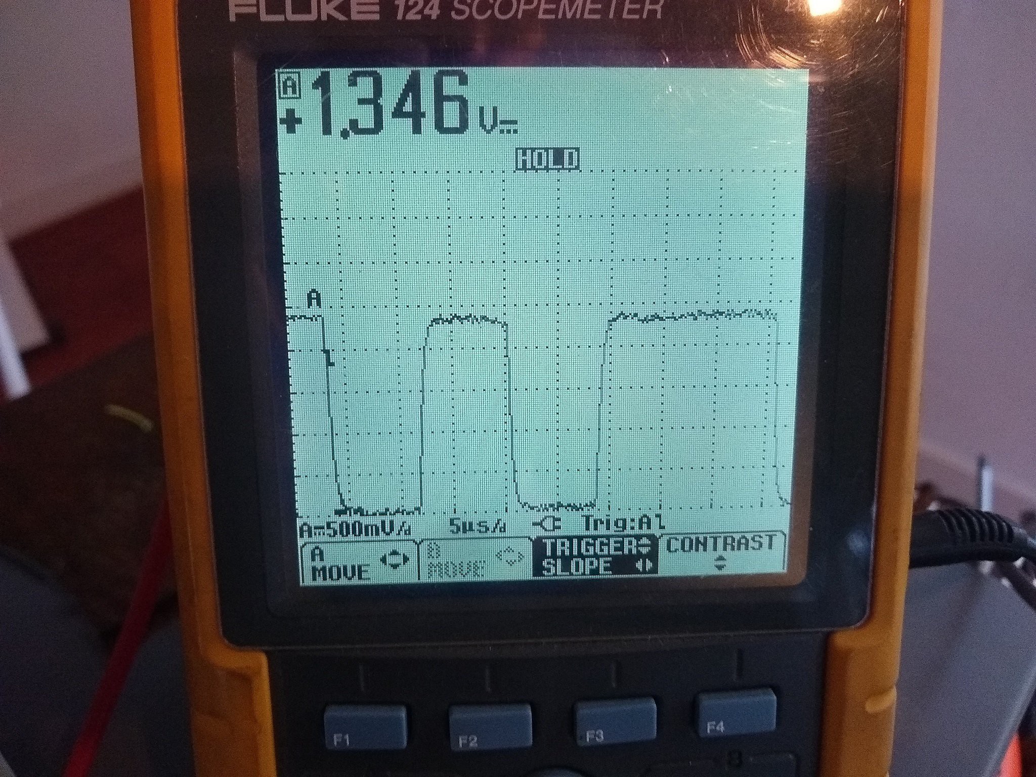
The commands to start and stop the datastream are harder to diagnose. It seems that a datastream is started and stopped. I get a databurst very 15ms on the scope.
![]()
Interpreting the data is something else though. I'm not getting through the state machine so more debugging is required.
It also seems the OTA gets quite unstable. sometimes I can reach the platform from the Arduino IDE, but an upload results in an error. I will have to figure this out more thoroughly, so all that's next.
Then use the class in some neat code and expand the class with some options:
- Detect when the roomba is docked (should be simple enough by checking the serial messages);
- Add control over music and LED's;
- Maybe add full drive capabilities.
-
Plans within plans within plans..
01/26/2022 at 18:40 • 0 commentsCode makes the difference between a small easy project using one thing on its own and the trouble of trying to combine different things. You can get lost in dependency hell pretty quickly.
I'm not a professional in any way so don't use my code to deliver insulin/beer with the Roomba. If my stuff doesn't blow up (when not intended) or becomes self aware and starts crying (when not intended) I'm already pretty happy.
To clean up the mess of code I have now, I have a few considerations. I want the code to do a few things asynchronous:
- Keep the WiFi connected;
- Run the OTA handler;
- Receive and interpret commands over MQTT;
- Publish status updates over MQTT;
- Sending commands to the Roomba when needed;
- Requesting, receiving and interpreting Roomba serial data stream;
- Communication with the IMU and interpreting the results;
- Do calculations and make decisions based on location and other inputs;
For this to work, I can't use any delays or while loops in my code. It's gonna be state machines all the way.
To restructure everything and wrap my head around it all, I started out with some pseudocode:
Includes
    - Roomba lib
    - Extras lib
    - OTA lib
    - pub-sub lib
    - MPU lib
    - I2C lib
    - JSON lib
Constants/defines:
    - WiFi details
        - SSID
        - Password
    - OTA details
        - Hostname
        - Password
    - IMU details
        - I2C address
        - MPU offsets
            - Xgyro, Ygyro, Zgyro, Zaccel
        - Callibration settings
    - MQTT details
        - Broker details
            - Server address
            - User
            - Password
        - Set/State topic
    - Extra details
        - LED pin
        - Debug level
Global vars:
    - Flags (volatile bool):
        - IMU GPIO interrupt flag
        - In Roomba class:
            - Sensors/data updated/ready
            - Bumped/wheel drop/cliff event
            - Charging flag
        -
    - States (char or uint8_t):
        - MQTT received command
        - In Roomba class:
            - Roomba state high level: charging, cleaning, driving, idle, off?
            - (Private) sub state
            - (Private) State for receiving data stream
            - (Private) State for sending commands
    - Roomba632 class:
        - Battery voltage
        - Battery charge
        - Current
        - Angle
        - Distance
    - MPU6050 class
        - MPU control/status vars
    - Orientation/motion vars
        - Cartesian local X,Y
        - Orientation
        - Track waypoint as JSON?
    - Timers (uint16_t):
        - Location calculation
        - In Roomba class:
            - Timer playing songs
    - WiFiCLient class
    - PubSubCLient class
Callbacks
- MQTT
    - Message received
        - check first char and set flags appropriately
    - reconnect with callback?
- IMU interrupt
    - set flag
Setup()
    - Serial start
    - WiFi start
    - OTA setup, Set on start/end/error, start OTA
    - MQTT setup callbacks, (re)connect/subscribe, start MQTT
    - I2C setup, start
    - Init IMU, callibrate, set ISR
    - Extras
OTA handler()
    -
Roomba handler()
    - in class:
        - public Functions set a flag (and variables) as a "request" witch is handled in order of priority:
            Clean()
            Dock()
            Spot()
            Stop()
            StartdataStream()
            StopDataStream()
            PlayMusic(song)
            Drive(with all variables)
        - private functions for stuff that's asynchronous:
            _StartDataStream()
                - Start, send request command
                - Datapackets requested:
                    - 15 Dirt detect uint8_t
                    - 22 Voltage uint16_t
                    - 23 Current int16_t
                    - 24 Battery temp int8_t
                    - 25 Battery charge uint16_t
                    - 26 Battery capacity uint16_t
                    - 35 Open interface mode uint8_t
                    - 37 Song playing? uint8_t
                    - 43 Encoder counts left int16_t
                    - 44 Encoder counts right int16_t
            _StopDataStream()
                - Start, send command
        - High level states. Can only be in one state at the time. Only change state from within state machine:
            - IDLE
                - keep alive
                - Check charging flag
            - Charging
                - Stop
                - Report charging state
            - Cleaning
                - Start, clean command, start datastream
                - Check charging flag
            - Driving
                - Start, full mode, evil lights, start datastream, drive
                - Check bump/stop etc flag
                - Check charging flag
            - Music
                - Start, full mode, evil lights, set timer, send song/command
        - Receiving data / stream
            (sensordatastream is one burst of max 172 bytes every 15ms at baudrate of115200 wich is plenty,
            refresrate of chargingdata is 1Hz)
            - Check if charging. Set charging flag
            - if not charging, get serial sensordata in order and update values. Check validity by checksum

MQTT message handler()
    - command received handler
        - States
Loop()
    - OTA handler
    - MQTT send (JSON / GPX files?)
    - Roomba message handler
        - State machine for sending commands and receiving response
    - Roomba handler
        - State machine
            - Charging
            - Driving
            - Cleaning
            - Music
    - Location calculation / logging
    - Extras handler
I think I'll start with the Roomba class in it's own library...
-
Adding direction to the project
01/23/2022 at 19:51 • 0 commentsI'm still in the proof of concept stage of the project. This mostly means reading A LOT of documentation on all components and figuring if they will play nice together.
Next up is an IMU. I would like to learn how to integrate different positioning data and play around with mapping.
The sensors on the Roomba should give me direction and distance measurements from the distance encoders on both wheels. It would be nice to complement this with another and independent source of data.
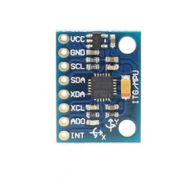
I have a MPU6050 board laying around. This is a small 3 axis accelerometer and gyroscope giving 6 degrees of freedom.
![MPU-6050 Accelerometer en Gyroscope 3-Axis Module 3.3V-5V]()
It operates on 3.3V, communicates using i2C and has an onboard DMP (Digital Motion Processor).
To utilize the full power of this device the DMP is the key. This way, I can offload some of the math to this external processor.
Time to get the prototyping sweater on. First up, connections:
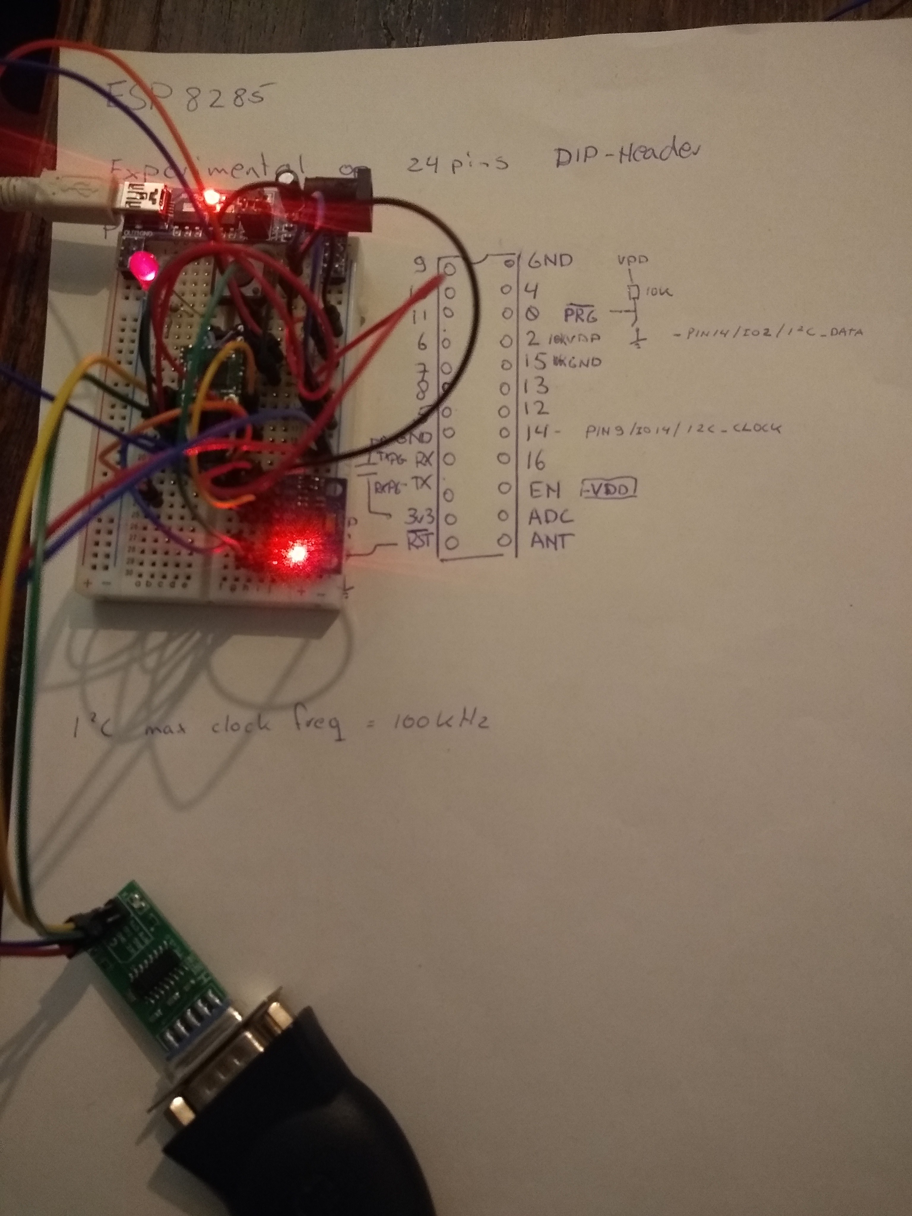
The ESP8266 datasheet says the i2C pins are pin9/GPIO14 for i2C_CLOCK and pin14/GPIO02 for i2C_DATA. (Table 4-4. page 14-15)
This is a potential problem because GPIO02 is pulled up with a 10K resistor for the proper boot up mode. Further reading the datasheet of the MPU6050 and reading up on the i2C protocol tell me the clock and data lines should be pulled up typically with 4.7K resistors anyway.
I first tried with 5k resistors and this worked. So then I tried with the 10K in place with the GPIO02 and this also seemed to work. This is good news because I should be able to just connect it to what I already have soldered and I don't have to replace the resistor.
GPIO14 is still freely available, so this will get a pullup resistor and that should be it.
The ADD pin on the MPU6050 allows to set the LSB of the address. So the address on the i2C bus can be 0x68 on low or 0x69 on high. I will connect it to GND on the board.
Lastly there is the possibility to use the interrupt pin. It will flag when the DMP has it's results ready so a ISR can get the values over the i2C bus. Because the interrupt is on the rising edge (according to the i2C MPU library), this can piggyback on the pulldown on GPIO15 on the ESP8266.
![]()
I then checked this setup using a i2C address scanner sketch I found here:
https://diyi0t.com/i2c-tutorial-for-arduino-and-esp8266/
#include "Wire.h"
#define SDA_PIN 2
#define SCL_PIN 14
const int16_t I2C_MASTER = 0x42;

void setup(){
  Serial.begin(115200);
  while(!Serial){} // Waiting for serial connection

  Serial.println();
  Serial.println("Start I2C scanner ...");
  Serial.print("\r\n");
  byte count = 0;

  Wire.begin(SDA_PIN, SCL_PIN, I2C_MASTER);        // join i2c bus (address optional for master)
  for (byte i = 8; i < 120; i++)
  {
    Wire.beginTransmission(i);
    if (Wire.endTransmission() == 0)
      {
      Serial.print("Found I2C Device: ");
      Serial.print(" (0x");
      Serial.print(i, HEX);
      Serial.println(")");
      count++;
      delay(1);
      }
  }
  Serial.print("\r\n");
  Serial.println("Finish I2C scanner");
  Serial.print("Found ");
  Serial.print(count, HEX);
  Serial.println(" Device(s).");
}

void loop() {}
This tells me a device is found on address 0x68. Normal boot up and programming via UART also still work, so we're in business.
I'm not sure if the Wire library uses the correct pins though and any on chip hardware or if it just does some bit bashing. If I don't specify the pins, the example sketch doesn't work. This leads me to think the hardware pins aren't configured in the board info for the Arduino IDE.
Next up is a sketch to get raw sensor data. For this I used the library from here:
https://github.com/jrowberg/i2cdevlib
I only had to change the pins being used for i2C by adding
#define SDA_PIN 2
#define SCL_PIN 14
const int16_t I2C_MASTER = 0x42;
And change the Wire.begin(); to
Wire.begin(SDA_PIN, SCL_PIN, I2C_MASTER);This gives me readings, so now it's time for the DMP sketch. For this to work I had to change a few more things. First of all the interrupt pin is GPIO15 and I also added a LED to GPIO9 (why not)
#define INTERRUPT_PIN 15  // use pin 15 on ESP8266 (has 10K pulldown for programming via UART)
#define LED_PIN 9 // (Arduino is 13, Teensy is 11, Teensy++ is 6)
And the max speed for i2C on the ESP8266 is 100kHz according to the datasheet. So:
Wire.setClock(100000); // 100kHz I2C clock.This would compile, but the ESP8266 crashed hard and the bootup message on the serial port would say something like:
20:08:22.373 -> load 0x4010f000, len 1384, room 16
20:08:22.373 -> tail 8
20:08:22.373 -> chksum 0x2d
20:08:22.373 -> csum 0x2d
20:08:22.373 -> v8b899c12
20:08:22.373 -> ~ld
20:08:22.431 -> ISR not in IRAM!Ok. google to the rescue. Apparently, the ISR (Interrupt Service Routine) has to be placed in a special place in memory: IRAM. To tell the IDE this, you need to add "ICACHE_RAM_ATTR " when declaring the ISR function like so:
void ICACHE_RAM_ATTR dmpDataReady() {
    mpuInterrupt = true;
}
And now it worked. I'm getting messages with calibrated and integrated results!
The real test was when trying to combine this sketch with the rest of the code, but it worked. Together with WiFi, OTA updates, MQTT pub-sub, Roomba commands and retrieving sensor data.
I can notice it's becoming unstable though. There is an error now when I upload the sketch OTA:
Uploading.................................................................................................................................................................
18:15:40 [ERROR]: No Result!
18:15:40 [ERROR]: No Result!And when I change something seemingly simple, it sometimes blows up, crashes and spews out nonsense or keeps rebooting. But it still works and proves all elements CAN work together.
Time to clean up the code, get it stable and add the MPU6050 to the "production" hardware together with the Buck step down DC/DC converter in stead of the LM7833.
-
Important high level stuff
01/22/2022 at 20:42 • 0 commentsOk. So it works and cleans my house on schedule. That's nice and all, but I noticed it can play tunes and I want more.
This project can't continue before it has come to life. I've spend at least a week getting this far and all I got was an extra scheduling feature that you can buy. But can you buy this??:
I don't think so! (because, why would you?)
Using a library to interface with the Roomba:
Up until now I commanded the Roomba with Serial.write commands. This is something like re-inventing the wheel (or using duct tape and a swiss army knife to build a bamboo plane). It's hard and inefficient.
So I decided to make use of a library someone else wrote. The iRobot documents point to this library: https://github.com/brinnLabs/Create2
On inspection, it uses way too much code. It uses two ways to write to serial in every command. It has all the scheduling functions which my Roomba doesn't have.
But it seems as good a start as any.
I started with removing all the double stuff and functions I don't need. I then tried to use it and get it to compile an run stable with all the other functions (OTA + MQTT).
When this was up and running, where back to where we were, but now with a library. That's just classy (see what I did there?)
Composing:
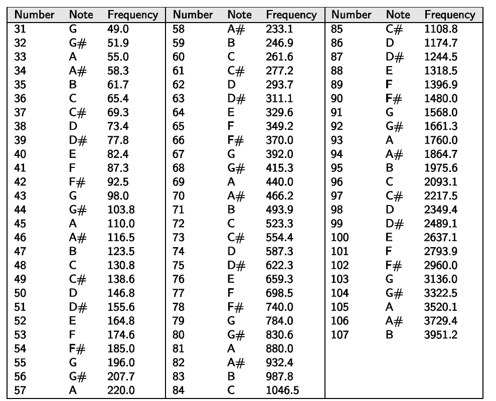
One of the reasons I chose this library is because it has all the MIDI notes defined in the header file:
enum notes{
	N_G1 = 31,
	N_G1S = 32,
	N_A1 = 33,
	N_A1S = 34,
	N_B1 = 35,
	N_C1 = 36,
	N_C1S = 37,
	N_D1 = 38,
	N_D1S = 39,
	N_E1 = 40,
	N_F1 = 41,
	N_F1S = 42,
	N_G2 = 43,
	N_G2S = 44,
	N_A2 = 45,
	N_A2S = 46,
*
*
	N_A7 = 105,
	N_A7S = 106,
	N_B7 = 107
};
And there is a struct for a "note":
struct Notes {
	byte note;
	byte duration;
};
It seems that I have to find the note and the duration and I can make it sing! Simple!
The Roomba lets you create 4 "songs" of 16 notes. These can then be recalled.
In the example:
Notes songNotes[16];
songNotes[0].note = 76;
songNotes[1].note = 76;
songNotes[2].note = 76;
songNotes[3].note = 76;
songNotes[4].note = 76;
songNotes[5].note = 76;
songNotes[6].note = 76;
songNotes[7].note = 79;
songNotes[8].note = 72;
songNotes[9].note = 74;
songNotes[10].note = 76;

songNotes[0].duration = 16;
songNotes[1].duration = 16;
songNotes[2].duration = 32;
songNotes[3].duration = 16;
songNotes[4].duration = 16;
songNotes[5].duration = 32;
songNotes[6].duration = 16;
songNotes[7].duration = 16;
songNotes[8].duration = 16;
songNotes[9].duration = 16;
songNotes[10].duration = 64;

roomba.createSong(1, 11, songNotes);

for(int i=0;i<11;i++){
    totalDuration1 += songNotes[i].duration;
}
roomba.playSong(1);
totalDuration1 = 100+1000*(totalDuration1/64.0);
delay(totalDuration1);
I couldn't find good source material for single notes, I don't have a piano at hand and I cant read musical notation (any more). So the best I could come up with is a Youtube tutorial play allong guitar hero style:
I then transcribed the played notes and length to code. But it sounded like my poor Roomba had had a severe stroke :|
I tried all sort of things and every try meant
- Type new iteration in code;
- Upload code OTA to Roomba;
- Wait for connection with MQTT-broker (it would announce its presence by publishing to it's state topic);
- Send command to it's MQTT command topic;
- Feel sorry for the Roomba and myself and GOTO label 1;
Then I noticed the notes in the library were WRONG! The notes have the wrong octave number!
The documentation gives the Frequency:
![]()
Comparing this to a Wiki page on MIDI notes tells me the octave number doesn't start with 1 like a normal person. But instead is offset from the letters like this:
enum notes{
	N_G2 = 31,
	N_G2S = 32,
	N_A2 = 33,
	N_A2S = 34,
	N_B2 = 35,
	N_C3 = 36,
	N_C3S = 37,
	N_D3 = 38,
The rollover in octave number is from B to C and not from G to A.
Now it started to sound reasonable.
I ended up with the following:
#include <ESP8266WiFi.h>    //For ESP8266
#include <PubSubClient.h>   //For MQTT
#include <ESP8266mDNS.h>    //For OTA
#include <WiFiUdp.h>        //For OTA
#include <ArduinoOTA.h>     //For OTA

#include <Roomba632.h>
Roomba632 roomba;

// WIFI configuration
#define wifi_ssid "***"
#define wifi_password "***"

//OTA configuration
const char* host = "Roomba632"; //84ed23
//const char* host = "ESP8285_Testplatform"; //80e74a
const char * sketchpass = "***";

// MQTT configuration
#define mqtt_server "192.168.1.***"
#define mqtt_user "***"
#define mqtt_password "***"
#define mqtt_sub_topic "homeassistant/device/roomba/set"
#define mqtt_pub_topic "homeassistant/device/roomba/state"
String mqtt_client_id= host;   //This text is concatenated with ChipId to get unique client_id
long lastReconnectAttempt = 0;


//Songs:
Notes macGyverNotes0[16] = {
  {N_B3, 16},
  {N_E4, 16},
  {N_A4, 16},
  {N_B4, 16},
  {N_A4, 16},
  {N_B3, 16},
  {N_E4, 16},
  {N_B3, 16},
  {0   , 16},
  {N_E4, 16},
  {N_A4, 16},
  {N_B4, 16},
  {N_A4, 16},
  {N_E4, 16},
  {N_B3, 16},
  {N_E4, 16}
};
Notes macGyverNotes1[16] = {
  {0   , 16},
  {N_E4, 16},
  {N_A4, 16},
  {N_B4, 16},
  {N_A4, 16},
  {N_B3, 16},
  {N_E4, 16},
  {N_B3, 32},
  {0   , 16},
  {N_A4, 16},
  {N_D5, 16},
  {N_C5, 16},
  {N_D5, 16},
  {N_C5, 16},
  {N_B4, 16},
  {N_A4, 16}
};
Notes macGyverNotes2[16] = {
  {N_B4, 48},
  {N_A4, 76},
  {0   , 4},
  {N_A4, 48},
  {N_G4, 76},
  {0   , 4},
  {N_B4,14},
  {0   , 2},
  {N_B4,48},
  {N_A4,76},
  {0   , 4},
  {N_A4, 48},
  {N_G4,32},
  {N_A4,72},  //klopt niet
  {0   , 8},
  {N_C5,12}
};
Notes macGyverNotes3[16] = {
  {0   , 2},
  {N_C5,12},
  {0   , 2},
  {N_C5,12},
  {0   , 2},
  {N_C5,12},
  {0   , 2},
  {N_C5,12},
  {0   , 2},
  {N_C5,12},
  {0   , 2},
  {N_B4,64},
  {N_F4S, 16},
  {N_A4, 32},
  {N_G4, 80},
  {N_C5, 14}
};
Notes macGyverNotes41[2] = { //speelt niet altijd?
  {0, 2},
  {N_C5, 32}
};
Notes macGyverNotes42[7] = {
  {N_B4, 32},
  {N_C5, 16},
  {N_B4, 16},
  {N_A4, 16},
  {N_G4, 16},
  {N_E5, 32},
  {N_A4, 64}
};
Notes macGyverNotes5[16] = {
  {N_C5, 14},
  {   0, 2},
  {N_C5, 80},
  {N_F4S, 16},
  {N_A4, 32},
  {N_G4, 76},
  {N_C5, 14},
  {   0,  2},
  {N_C5, 32},
  {N_B4, 32},
  {N_C5, 16},
  {N_B4, 16},
  {N_G4, 16},
  {N_E5, 32},
  {N_A4,64},
  {N_B4,64}
};
Notes macGyverNotes6[16] = {
  {N_C5,16},
  {N_B4,16},
  {N_A4,16},
  {N_C5,32},
  {N_B4,16},
  {N_A4,16},
  {N_D5,32},
  {N_C5,16},
  {N_B4,16},
  {N_D5,32},
  {N_C5,16},
  {N_B4,16},
  {N_E5,32},
  {N_D5,16},
  {N_E5,16},
  {N_F5S,32}
};
Notes macGyverNotes7[16] = {
  {N_B4,32},
  {N_G5S,48},
  {N_F5S,32},
  {N_F5,32},
  {N_B4,32},
  {N_G5,16},
  {N_E5,16},
  {N_B4,16},
  {N_F5S,16},
  {N_D5,16},
  {N_A4,16},
  {N_E5,16},
  {N_C5,16},
  {N_G4,16},
  {N_D5,16},
  {N_B4,16}
};
Notes macGyverNotes8[16] = {
  {N_G4,16},
  {N_C5,16},
  {N_E4,16},
  {N_B4,16},
  {N_D4,16},
  {N_C5,16},
  {N_B4,16},
  {N_A4,16},
  {N_G4,16},
  {N_A4S,32},
  {N_A4,32},
  {N_G5,16},
  {N_G4,16},
  {N_D5,16},
  {N_G4,16},
  {N_D5S,16}
};
Notes macGyverNotes9[16] = {
  {N_D4S,16},
  {N_A4S,16},
  {N_A4,16},
  {N_G4,16},
  {N_G3,16},
  {N_D4,16},
  {N_G3,16},
  {N_D4S,16},
  {N_G3,16},
  {N_A3S,16},
  {N_A3,16},
  {N_G3,14},
  {   0, 2},
  {N_G3,14},
  {   0, 2},
  {N_G3,14}
};
Notes macGyverNotes10[9] = {
  {   0, 2},
  {N_G3,14},
  {   0, 2},
  {N_G3,14},
  {   0, 2},
  {N_G3,14},
  {   0, 2},
  {N_G3,14},
  {   0, 2}
};
Notes denyNotes[3] = {
  {N_E4, 4},
  {N_E4, 4},
  {N_E4, 4}
};
int totalDuration =0;

void callback(char* topic, byte* payload, unsigned int length) {
  // handle message arrived
  // Serial.println("message received");
  //String strContent = "";
  //for (int i = 0; i < length; i++) {
  //  strContent += (char)payload[i];
  //}
  //Serial.println();
  char command = payload[0];
  // Switch case for commands only uses first char
  switch (command) {
    case 'C': //Clean
      roomba.start();
      roomba.safeMode();
      delay(200);
      roomba.clean();
      delay(5000);
      roomba.setPowerLEDs(64, 64);
      break;
    case 'D': //Dock
      roomba.start();
      roomba.safeMode();
      delay(200);
      roomba.seekDock();
      delay(5000);
      roomba.setPowerLEDs(32, 64);
      break;
    case 'S': //Spot
      roomba.start();
      roomba.safeMode();
      delay(200);
      roomba.spotClean();
      delay(5000);
      roomba.setPowerLEDs(96, 64);
      break;
    case 'M': //Music
      roomba.start();
      roomba.fullMode();
      delay(200);
      roomba.setPowerLEDs(112, 128);
      delay(200);
      playMIDI(macGyverNotes0,16);
      playMIDI(macGyverNotes1,16);
      playMIDI(macGyverNotes2,16);
      playMIDI(macGyverNotes3,16);
      playMIDI(macGyverNotes41,2);
      playMIDI(macGyverNotes42,7);
      playMIDI(macGyverNotes5,16);
      playMIDI(macGyverNotes6,16);
      playMIDI(macGyverNotes7,16);
      playMIDI(macGyverNotes8,16);
      playMIDI(macGyverNotes9,16);
      playMIDI(macGyverNotes10,9);
      roomba.passiveMode();
      break;

    default: //Play tune (also stops a motion action)
      roomba.start();
      roomba.fullMode();
      delay(200);
      roomba.setPowerLEDs(112, 128);
      delay(200);
      playMIDI(denyNotes,3);
      roomba.safeMode();
      break;
  }
}

// Start MQTT client
WiFiClient espClient;
PubSubClient mqtt_client(espClient);

// Necesary to make Arduino Software autodetect OTA device
//WiFiServer TelnetServer(8266);

void setup() {
  Serial.begin(115200);
  WiFi.begin(wifi_ssid, wifi_password);
  while (WiFi.status() != WL_CONNECTED) {
    delay(500);
  }
  ArduinoOTA.onStart([]() { //Make sure device is in a safe mode
    //store params to EEPROM?
  });
  ArduinoOTA.onEnd([]() { //Device will reboot

  });
  ArduinoOTA.onError([](ota_error_t error) {
    (void)error;
    ESP.restart();
  });
  ArduinoOTA.begin();
  mqtt_client.setServer(mqtt_server, 1883);
  mqtt_client.setCallback(callback);
  // Serial.println("Ready");
}
void playMIDI(Notes ArrayOfNotes[], int ArraySize){
  roomba.createSong(1, ArraySize, ArrayOfNotes);
  totalDuration = 0;
  for(int i=0;i<ArraySize;i++){
    totalDuration += ArrayOfNotes[i].duration;
  }
  roomba.playSong(1);
  totalDuration = 100+1000*(totalDuration/64.0);
  delay(totalDuration);
}
boolean attempt_reconnect() {
  if (mqtt_client.connect(mqtt_client_id.c_str(), mqtt_user, mqtt_password)) {
    // Once connected, publish autodiscover config message and current state..
    mqtt_client.publish(mqtt_pub_topic, "up");
    // ... and resubscribe
    mqtt_client.subscribe(mqtt_sub_topic);
    // Serial.println("connected");
  }
  else {
    // Serial.print("failed, rc=");
    // Serial.print(mqtt_client.state());
    // Serial.println(" try again in 5 seconds");
  }
  return mqtt_client.connected();
}
void mqtt_handler() {
  //Serial.println("MQTT-handler");
  if (!mqtt_client.connected()){
    if (millis() > (lastReconnectAttempt + 5000)) {
      lastReconnectAttempt = millis();
      // Attempt to reconnect
      // Serial.println("attempt to reconnect");
      if (attempt_reconnect()) {
        lastReconnectAttempt = 0;
      }
    }
  }
  else {
    // Client connected
    // Serial.println("connected to MQTT broker");
    mqtt_client.loop();
  }
}
void loop() {
  ArduinoOTA.handle();
  mqtt_handler();

  //
}
The code is still not prettyfied, but I also have done so much to the library that I'm not sure if I want to keep all this.
-
Roomba's first squeaks
01/22/2022 at 19:18 • 0 commentsThere are plenty of Roomba builds to find on the interwebs. This is a blessing, but can also be a bit of a curse. None are exactly what I wanted to do. Mostly in bits, but whenever you combine bits and pieces and libraries from different sources in the Arduino IDE, it all goes to.... well it doesn't go. You know it's possible, but HOW?
My particular setup and wishes:
- Communicate with Home Assistant through MQTT;
- Able to do updates OTA;
- Command Roomba;
And for the future:
- Receive data-streams from Roomba over serial;
- Receive IMU-data from MPU6050 over I2C;
- Use the DMP (Digital Motion Processor) on the MPU6050 with the interrupt;
- Do calculations with acquired data;
Most of the projects and examples I come across do single things and use delays or while loops somewhere. This doesn't suit my wishes, so I ended up rewriting a lot of stuff.
It's all a work in progress and will be neater, I promise. For now It's all a bit of a proof of concept.
I started with the OTA stuff:
https://randomnerdtutorials.com/esp8266-ota-updates-with-arduino-ide-over-the-air/
https://arduino-esp8266.readthedocs.io/en/latest/ota_updates/readme.html
I ended up using the example from the Arduino IDE from the ESP8266 board 'add-on'. In the IDE --> preferences --> add as extra boards:
http://arduino.esp8266.com/stable/package_esp8266com_index.json
I have to use 'Generic ESP8285 Module' as board. Check out the examples for the OTA example.
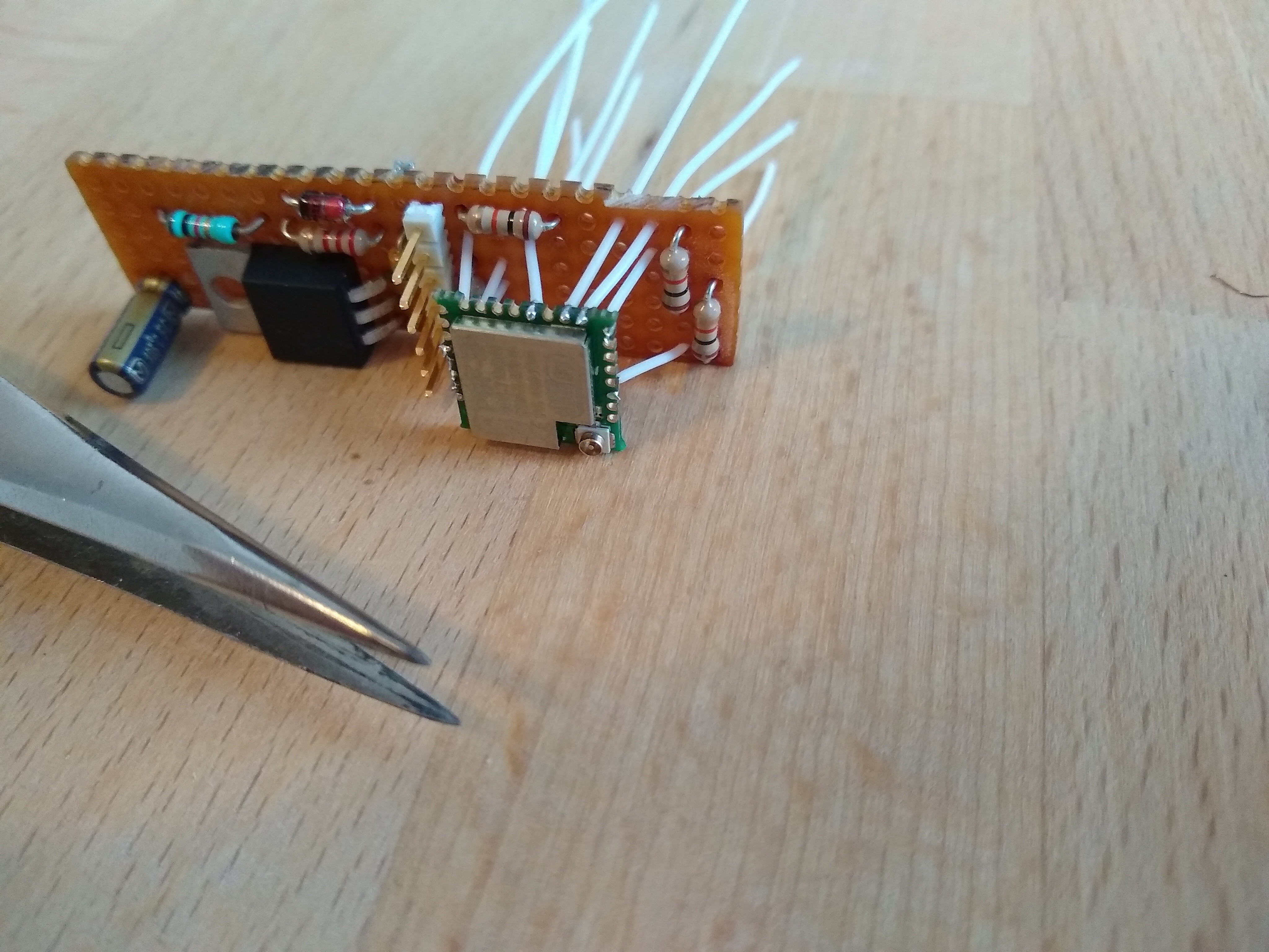
This feature is part of the running code though. So when (not if) my software gets stuck somewhere, or it loses connection to the WiFi and isn't able to reconnect. I can't upload a fix and have to disassemble the Roomba to upload software via serial. I kind of get a glimpse in the mindset of NASA and the engineers on the JWST.
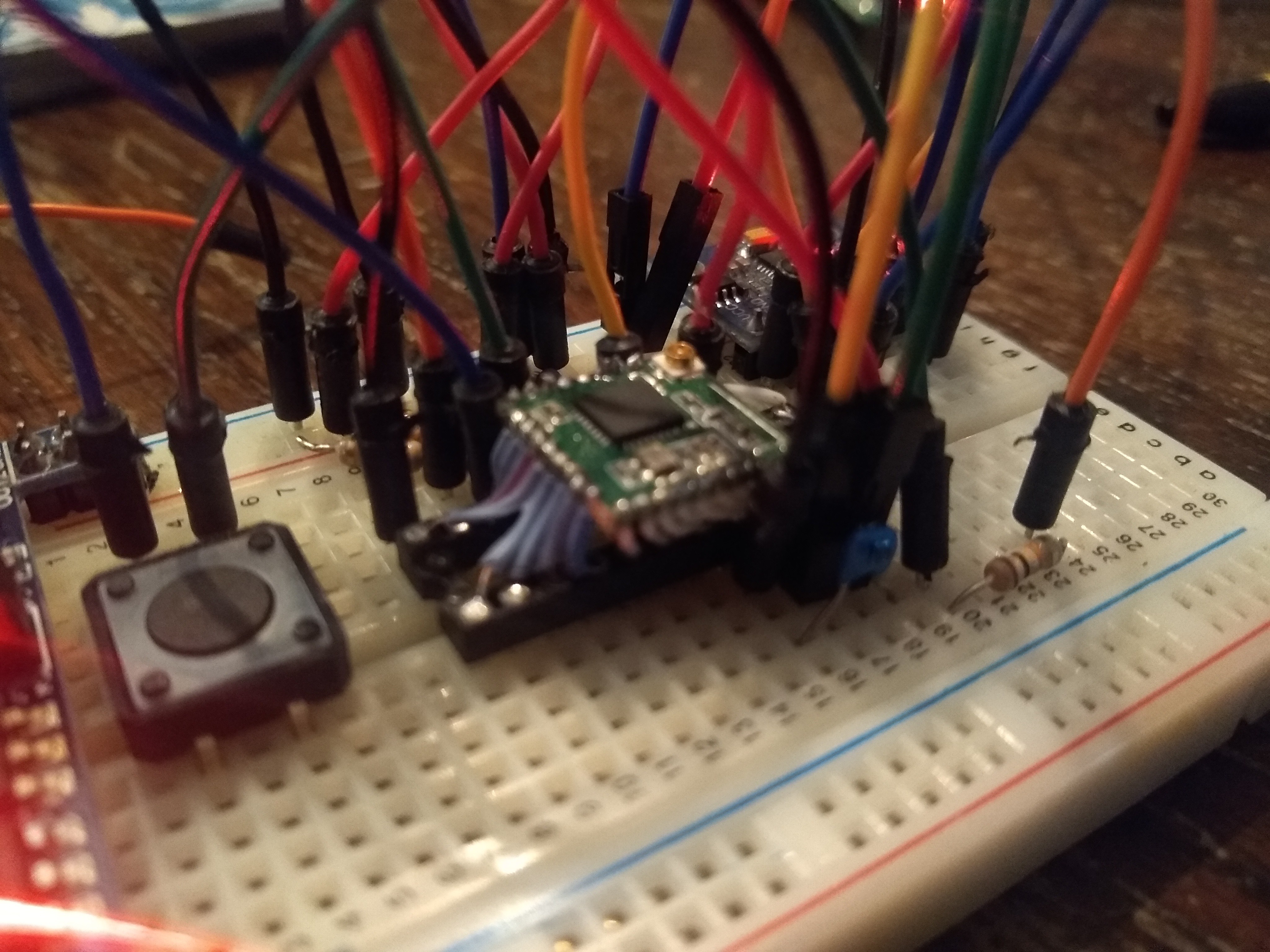
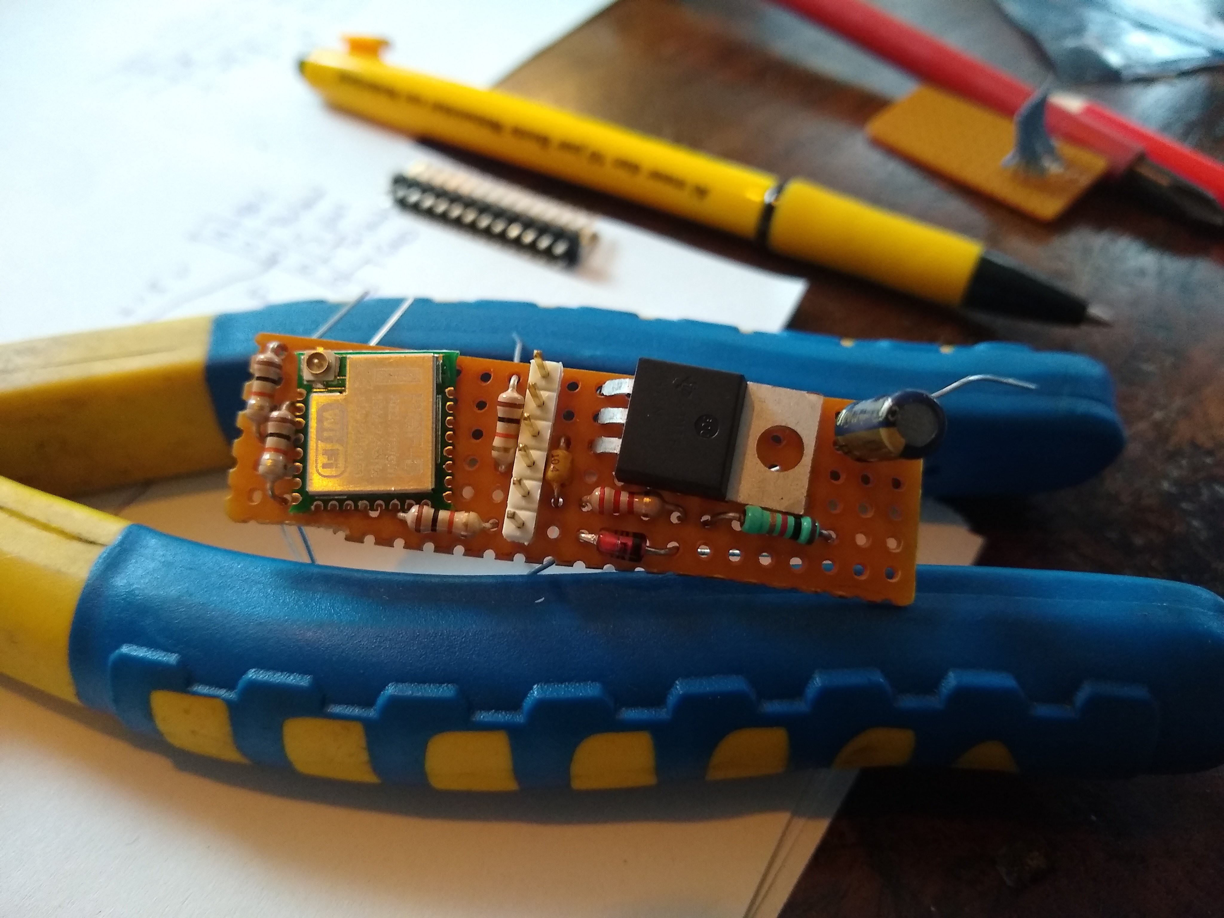
This is where my second ESP8266 that I soldered to a DIP24 connector comes in. I have this setup on a breadboard and connected to my laptop via serial.
![]()
I can upload software OTA to this board first to check if the connection holds and I can still send new software to it. I've been very happy with this setup several times. Especially when using callbacks, pointers to arrays, interrupt service routines and a mix of libraries from different sources. I've had several stack overflows, illegal register requests and other. Whenever this happens, the ESP8266 can spit out a stack trace and and exception cause and you get some clues as to what went wrong.
https://arduino-esp8266.readthedocs.io/en/latest/faq/a02-my-esp-crashes.html
Communication with HA via MQTT:
Next, with a stable connection, I want to get some communication via MQTT so I can send commands and receive status updates when I can't connect physically. For this, I use the PubSubClient library.
https://github.com/knolleary/pubsubclient
Now we have two libraries / examples that both use some internet connection. They use a different library / class for the web-client though. And then it becomes a challenge to combine the two functions in one sketch.
#include <ESP8266WiFi.h>    //For ESP8266
#include <PubSubClient.h>   //For MQTT
#include <ESP8266mDNS.h>    //For OTA
#include <WiFiUdp.h>        //For OTA
#include <ArduinoOTA.h>     //For OTA

// WIFI configuration
#define wifi_ssid "***"
#define wifi_password "***"

//OTA configuration
//const char* host = "Roomba632"; //84ed23
const char* host = "ESP8285_Testplatform"; //80e74a
const char * sketchpass = "***";

// MQTT configuration
#define mqtt_server "192.168.1.***"
#define mqtt_user "***"
#define mqtt_password "****"
#define mqtt_sub_topic "homeassistant/device/roomba/set"
#define mqtt_pub_topic "homeassistant/device/roomba/state"
String mqtt_client_id= host;   //This text is concatenated with ChipId to get unique client_id
long lastReconnectAttempt = 0;

void callback(char* topic, byte* payload, unsigned int length) {
  // handle message arrived
  // Switch case for commands only uses first char
  switch (command) {
    case 'C': //Clean
      Serial.write(128);
      Serial.write(135);
      break;
    case 'D': //Dock
      Serial.write(128);
      Serial.write(143);
      break;
    case 'S': //Spot
      Serial.write(128);
      Serial.write(134);
      break;
    case 'M': //Music
      Serial.write(128);
      Serial.write(140);
      Serial.write(1);
      Serial.write(3);
      Serial.write(48);
      Serial.write(32);
      Serial.write(52);
      Serial.write(32);
      Serial.write(55);
      Serial.write(32);
      Serial.write(141);
      Serial.write(1);
      break;
    default: //Play tune
      Serial.write(128);
      Serial.write(135);
      break;
  }
}
// Start MQTT client
WiFiClient espClient;
PubSubClient mqtt_client(espClient);

// Necesary to make Arduino Software autodetect OTA device
//WiFiServer TelnetServer(8266);

void setup() {
  Serial.begin(115200);
  WiFi.begin(wifi_ssid, wifi_password);
  while (WiFi.status() != WL_CONNECTED) {
    delay(500);
  }
  ArduinoOTA.onStart([]() { //Make sure device is in a safe mode
    //store params to EEPROM?
  });
  ArduinoOTA.onEnd([]() { //Device will reboot

  });
  ArduinoOTA.onError([](ota_error_t error) {
    (void)error;
    ESP.restart();
  });
  ArduinoOTA.begin();
  mqtt_client.setServer(mqtt_server, 1883);
  mqtt_client.setCallback(callback);
  // Serial.println("Ready");
}
boolean attempt_reconnect() {
  if (mqtt_client.connect(mqtt_client_id.c_str(), mqtt_user, mqtt_password)) {
    // Once connected, publish autodiscover config message and current state..
    mqtt_client.publish(mqtt_pub_topic, "up");
    // ... and resubscribe
    mqtt_client.subscribe(mqtt_sub_topic);
    // Serial.println("connected");
  }
  else {
    // Serial.print("failed, rc=");
    // Serial.print(mqtt_client.state());
    // Serial.println(" try again in 5 seconds");
  }
  return mqtt_client.connected();
}
void mqtt_handler() {
  //Serial.println("MQTT-handler");
  if (!mqtt_client.connected()){
    if (millis() > (lastReconnectAttempt + 5000)) {
      lastReconnectAttempt = millis();
      // Attempt to reconnect
      // Serial.println("attempt to reconnect");
      if (attempt_reconnect()) {
        lastReconnectAttempt = 0;
      }
    }
  }
  else {
    // Client connected
    // Serial.println("connected to MQTT broker");
    mqtt_client.loop();
  }
}
void loop() {
  ArduinoOTA.handle();
  mqtt_handler();
  //
}
It's not real pretty, but it works! Next up: add more stuff!
-
Add hardware
01/22/2022 at 17:56 • 0 commentsFor my goals I have the following setup in mind:
Microcontroller: ESP8266
https://hackerstore.nl/Artikel/1020
https://wiki.iteadstudio.com/PSF-A85
This is a unit I have worked with earlier. So I know how to set it up and program it.
I can upload firmware OTA (Over The Air). So I don't need any headers or wires exposed and it can remain in it's docking when I'm trying new stuff. This does mean I want to build a second prototyping setup where I can try out new software and check if the upload still works. This way I don't have to disassemble the Roomba every time my code breaks.
![]()
It will have a header for the first upload. This header will provide power, ground, connection to reset and program pins and 3.3V level Tx and Rx UART.
Power will come from the Roomba battery. I'm using a LM7833 linear voltage regulator to provide the 3.3V. I'm going to change this later (don't have the parts a.t.m.) because it has to dissipate quite some power. The battery level can get to 17V. The ESP8266 can draw 100mA. Normal operating conditions ~80mA. This means the LM7833 dissipates about (17V-3.3V)*0.1A=1.37W That's a bit much and absolutely unnecessary.
I've ordered a few Buck DC/DC step down converters. To provide the 3.3V later.
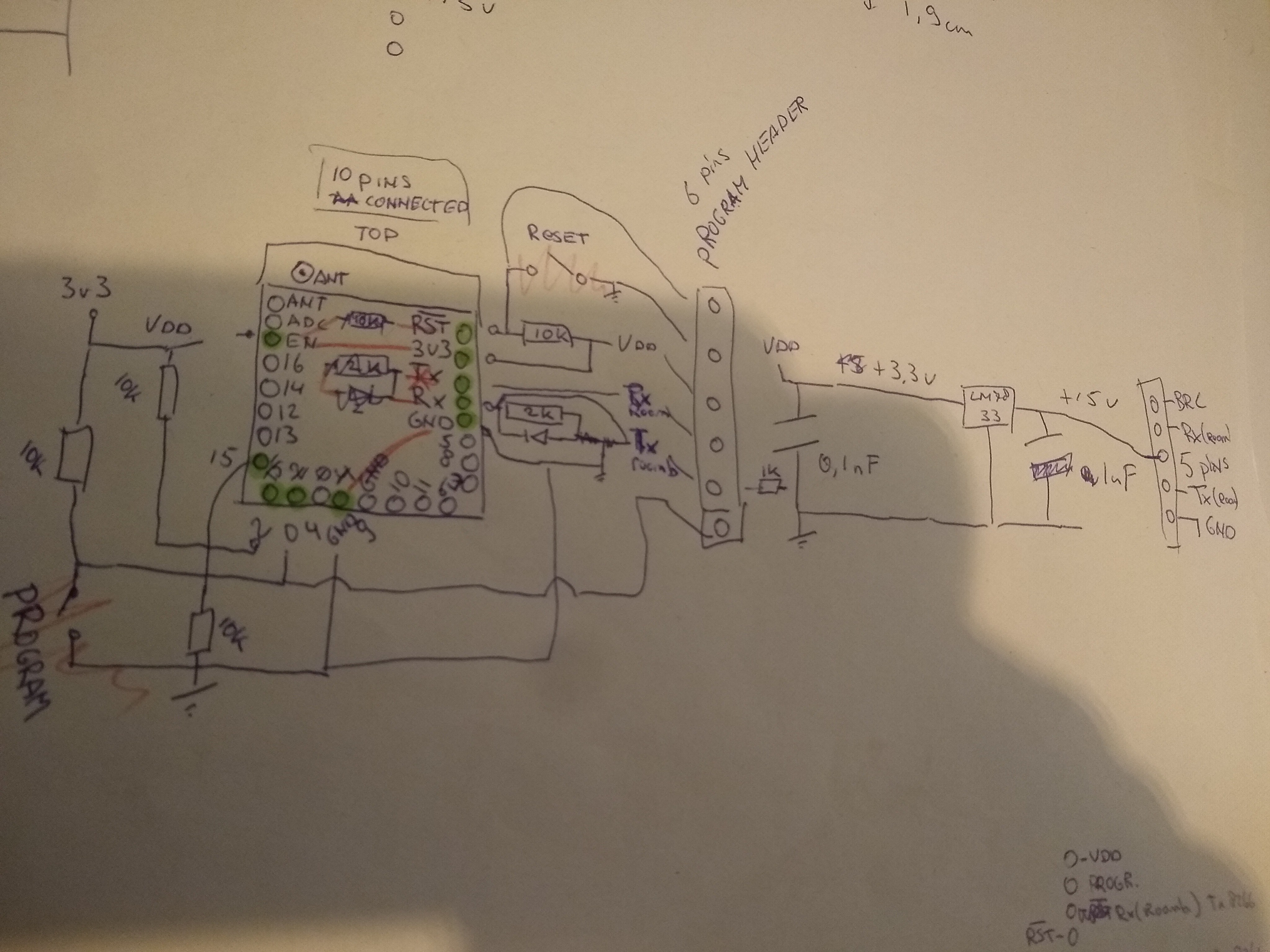
Connections / sketch to get my head around it all:
![]()
- The Rx pin on the (3.3V) ESP8266 will need the voltage divider level shifter to be connected to the (5V) Tx on the Roomba. Also a 3.3V Zener to GND, just to be sure;
- The Tx pin can be connected without any level shifting. The 3.3V is enough to be seen as a logic 1 by the Roomba;
- VDD: 3.3V (with 100nF);
- GND: on 2 pins;
The ESP8266 board I'm using needs some connections to get it in the proper boot- and operating mode:
- RSTB: Inverse reset. Pulled up with 10K to VDD;
- EN: Chip Enable. Connected straight to VDD;
- PRGB: UART programming select (inverse). Pulled up with 10K to VDD and connected to header so I can switch off-board;
- GPIO02: Pulled up with 10K to VDD to provide proper boot up mode. (will also be I2C_DATA pin for MPU6050);
- GPIO15: Pulled down with 10K to provide proper boot up mode. (will also receive interrupt from MPU6050 DMP, rising slope);
- GPIO14: Pulled up with 5k to VDD and will be connected to I2C_CLOCK pin on MPU6050;
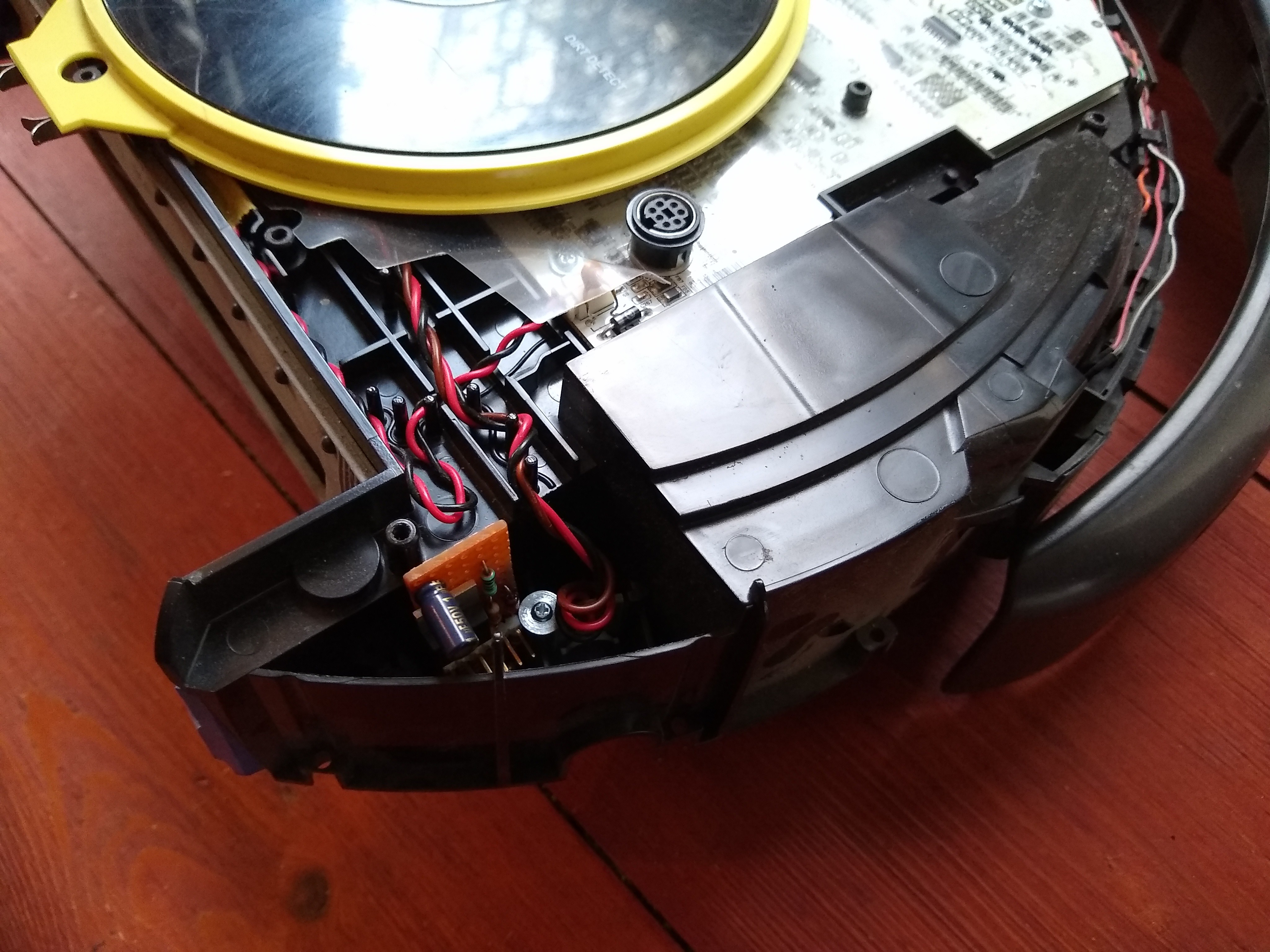
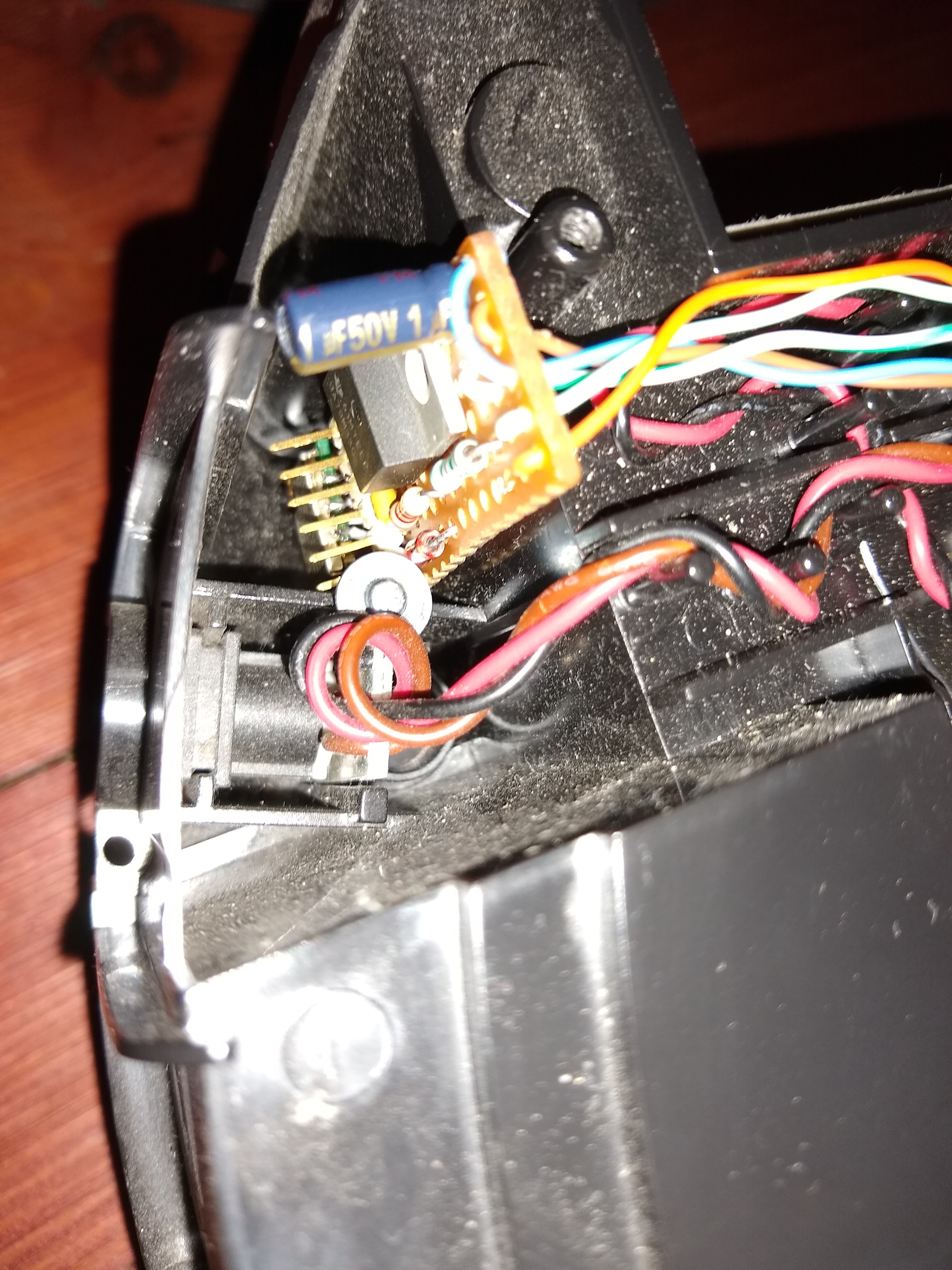
Time to open up the Roomba to find a empty space where my hardware can live:
![]()
Behind the right wheel, there is space and it's quite close to the serial connector. Measuring gives me a board of 5.9cm x 1.9cm. Plenty!
Something like this:
![]()
Testfit:
![]()
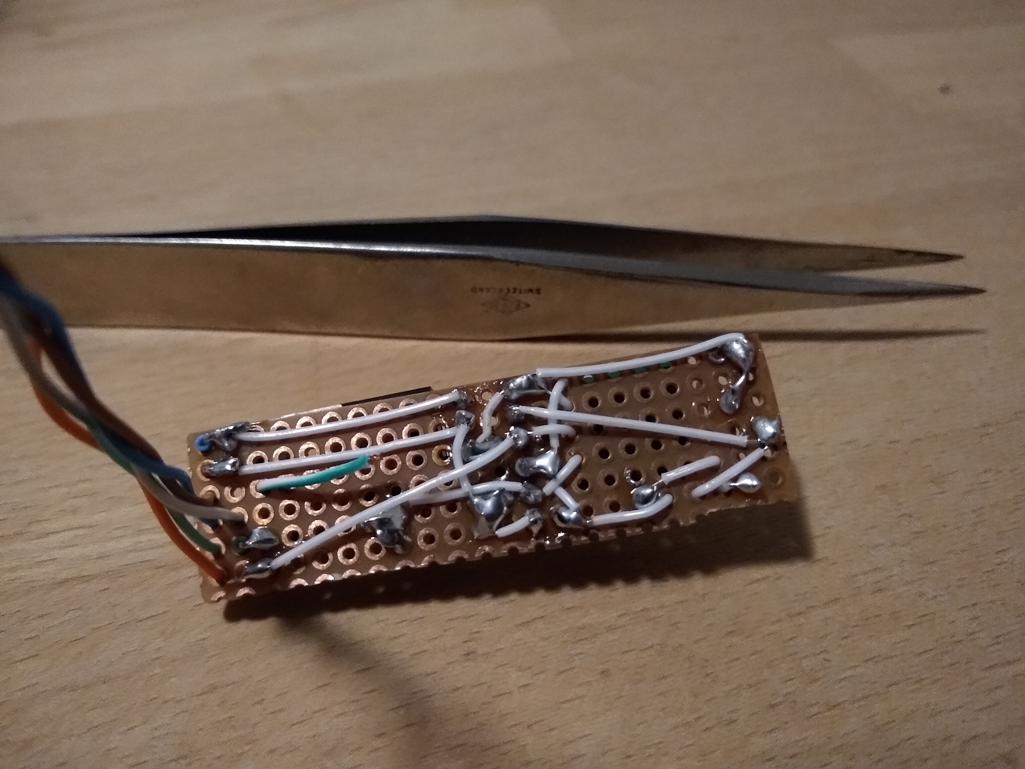
Finally some soldering:
![]()
And this is where I made the mistake to NOT correct myself when I mixed up the intended colours for the connection wires. I noticed it, but thought "this will be fine, I will remember".
Narrator: "But he didn't remember...."
Long story short: When connecting to the Roomba one time, I connected the ESP8266-Tx (orange) to the Roomba's raw battery voltage. So that's one ESP8266 down.. good thing they are cheap. I could also pretty neatly de-solder the unit and replace it with a new one.
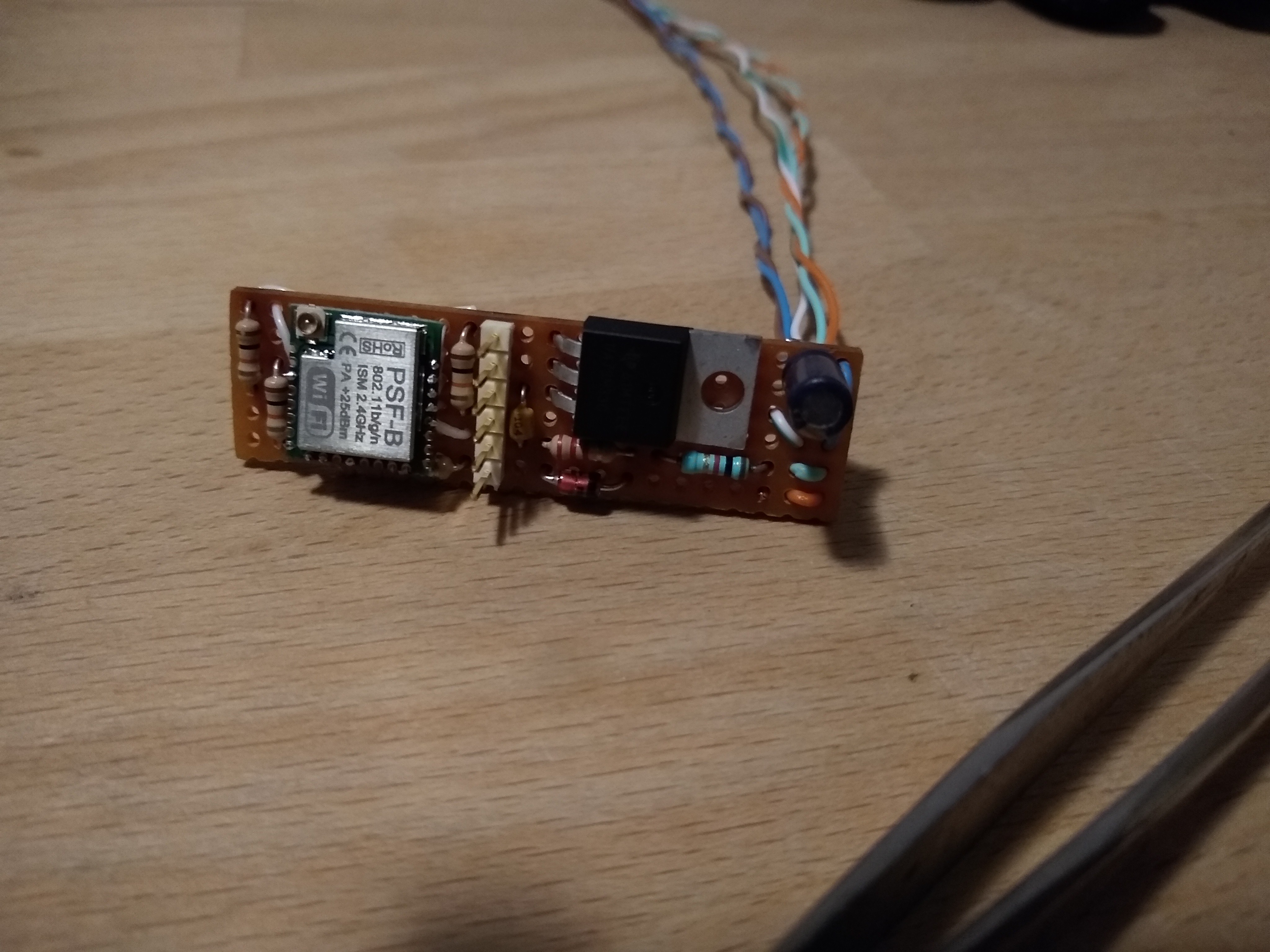
![]()
![]()
![]()
I connected the wires to the mini DIN7 connector by soldering the ends and just jamming them in. For the GND and VDD I bended two leads and soldered them to the end of the wires. So they can use two pins both.
From the docs: Pins 1 and 2 (Vpwr) are connected to the Roomba battery through a 200 mA PTC resettable fuse. The continuous draw from these two pins together should not exceed 200 mA. Do not draw more than 500 mA peak from these pins, or the fuse will reset.
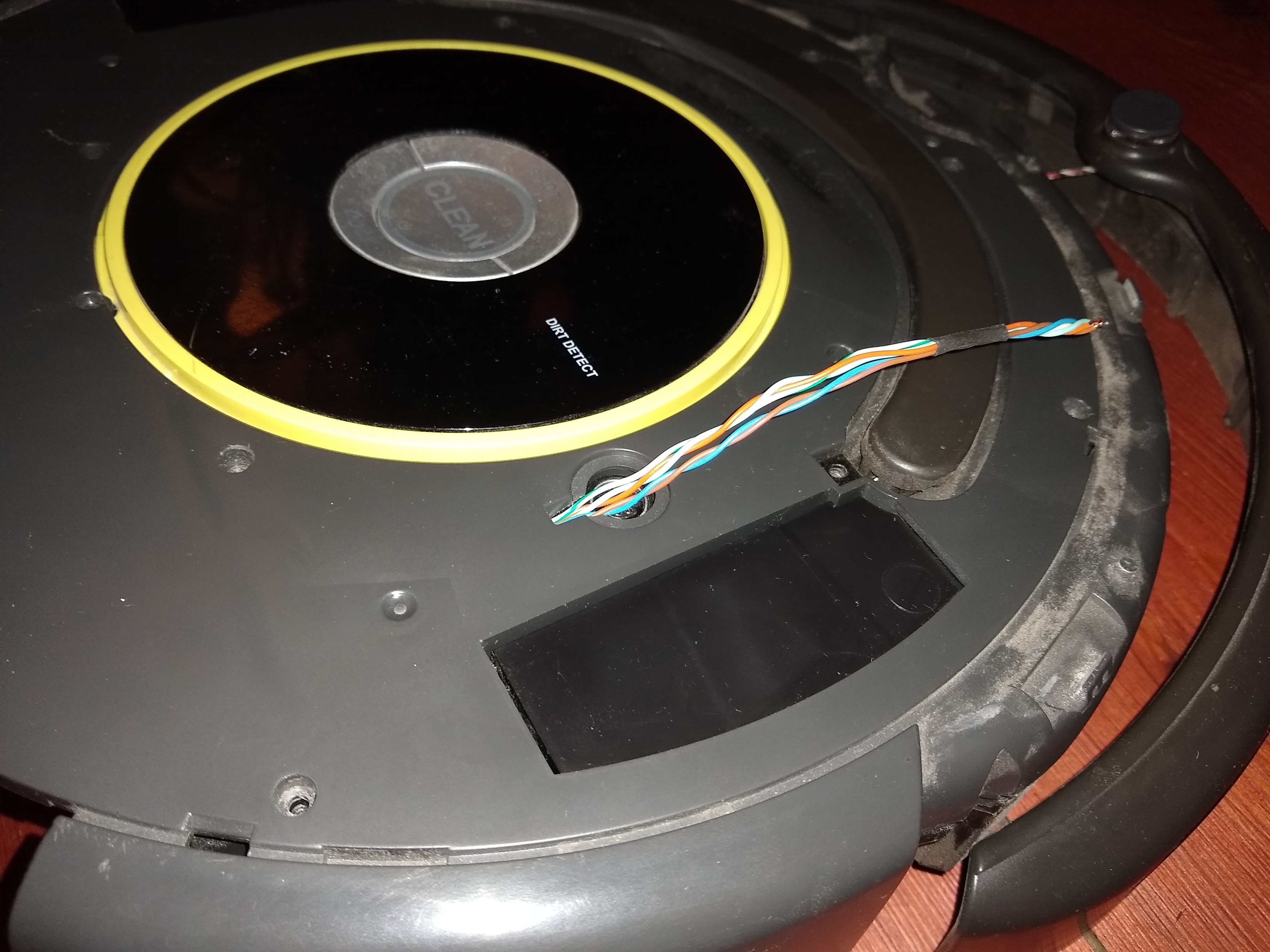
![]()
Also drilled one hole in the cover to let the wires come through. This will all be covered with a top plate and won't show.
And the first version of the hardware is DONE!
As said, I will sort out the power situation. It works for now. Next up, SOFTWARE!
-
Interfacing
01/22/2022 at 16:23 • 0 commentsFirst off I want to interface my laptop via serial to the Roomba. Send some commands, get some response.
Some places I found info and inspiration:
https://github.com/johnboiles/esp-roomba-mqtt
https://github.com/incmve/Roomba-esp8266-MQTT
https://www.hackster.io/mjrobot/controlling-a-roomba-robot-with-arduino-and-android-device-56970dAs always, ifixit has info on how to remove covers and the battery without destroying anything.
https://www.ifixit.com/Device/iRobot_Roomba_630
And a lot of documentation can be found on the iRobot site.
https://edu.irobot.com/what-we-offer/create-robot
Including the "iRobot® Create® 2 Open Interface (OI) Specification based on the iRobot® Roomba® 600"
That sounds like exactly what I need! And it includes the pinout and baudrate. So lets start there.
Pin Name Description
1 Vpwr Roomba battery + (unregulated)
2 Vpwr Roomba battery + (unregulated)
3 RXD 0 – 5V Serial input to Roomba
4 TXD 0 – 5V Serial output from Roomba
5 BRC Baud Rate Change
6 GND Roomba battery ground
7 GND Roomba battery groundProbing around with the scope reveals data on the TXD when turning the Roomba "on" or "off" (pushing the clean button)
I have a USB-Serial cable I also use for programming. It uses 3.3V logic levels though so I need some sort of level conversion. The ESP8266 I want to use also uses 3.3V, so this is a thing I have to tackle anyway.
On the iRobot site they even recommend a voltage level shifting circuit using a FET. Other options I found just use a voltage divider using two resistors.
I tried both circuits to check rise times / edges. The voltage divider seems to do adequately.
![]()
With the FET I would also need a regulated 5V source which I don't plan to have when everything is built in.
A voltage devider will do. I'm using 2K and 1K.
Now, when I connect it to my laptop I get the following message when it is turned on:
key-wakeup
slept for 0 minutes 12 seconds
2012-03-22-1549-L
r3_robot/tags/release-3.2.6:4975 CLEAN
bootloader id: 470B 575B 67CC BFFF
assembly: 3.3
revision: 0
flash version: 10
flash info crc passed: 1
battery-current-zero 254This tells me I have the correct firmware version. It has the Open Interface and I won't have any problems with a sleep state when charging.
Now to send commands. The interface expects raw byte data. No ASCII-characters or any formatting. This can't be done with the serial monitor provided with the Arduino IDE.
You need something like Realterm (https://realterm.sourceforge.io/) with this, you can send single bytes.
![]()
I thought it wasn't responding to any input at first. You send it byte 128 to start the interface and then you can command it to go in a 3 'modes'. 'passive', 'safe' or 'full'.
I had it on some axle stands/coffee cups so it wouldn't spontaneously drive of my table. It took me quite a while to figure out why it wasn't responding to my commands. But it turns out to be because of the dropped wheels! When it is in 'safe mode' and it senses a wheel being dropped it will revert to 'passive mode'. Because of the wheels being dropped, it needed to operate in 'full mode' to accept drive commands.
In mandatory hacker-voice:
"we're in!"
Old Roomba, new tricks
Add mapping & MQTT-interfacing with ESP8266 and an IMU