SimonXi
-
#11 Interesting Chemistry with TFT_eSPI library
10/13/2022 at 02:30 • 1 commentJust having the display is far from our purpose, we need it to show colorful, dynamic and meaningful information. For that, we need a powerful and user-friendly graphic library, I have searched high and low and found out that the TFT_eSPI library might just be the right fit!
TFT_eSPI is a very interesting and powerful Arduino library, you can use it for sensor data display in a meter form, you can also use it to display some important information (such as resistor color code), and you can even connect to the internet via the 5G WiFi on the BW16 to get the time and date and display on the screen as an internet clock, and even put your favorite movie poster in it and add animation to watch it again and again 😎
Let's watch a video together to see all the above-mentioned features in action,
I found this library works really well with BW16-Stamp, so I have created Pull Request on Github to add board configuration to the library, this way we can easily develop GUI feature for BW16-Stamp~
The arduino sketch code used in the demo are from a maker VolosR, here are the link to his Github repository,
https://github.com/VolosR/InternetClock180x60
-
#10 A good display need an input method
10/06/2022 at 07:39 • 0 commentsST7737 TFT SPI LCD display is a vivid and compact display that offer just enough visualization for many microcontrollers and their applications. However, a display without an input method feels void and not interesting, thus I plan to add an input method to the BW16 Stamp!
There are many options out there,
1. Push Buttons
This is the most obvious and easiest ones to add, TTGO dev board has 2 user buttons on the sides of their microcontroller board and are perfect for many applications
But buttons are huge for BW16 Stamp and limited to only max 4 states (with 2 buttons) which might not be enough.
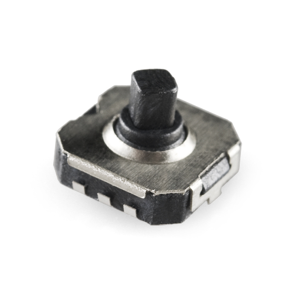
2. 5-way Tactile Switch
5-way tactile switch is just like a joy stick, but it can be slided up, down, right, left and pressed down, so essentially it's a 5-in-1 buttons
![5-way Tactile Switch]() This is good when you have many GPIO available, but for BW16 Stamp, our GPIO resources are also limited, so taking up 5 GPIO is a little to much.
This is good when you have many GPIO available, but for BW16 Stamp, our GPIO resources are also limited, so taking up 5 GPIO is a little to much.3. Thumbwheel Switch
This switch allows for rotation input, and press-down input which is very common on old-shool MP3/MP4 players
![Picture 1 of 12]() This is almost perfect, as it only need 3 GPIOs, but its size is still too big for our BW16 Stamp...
This is almost perfect, as it only need 3 GPIOs, but its size is still too big for our BW16 Stamp...4. 6-Axis Accelerometer + Gyro sensor
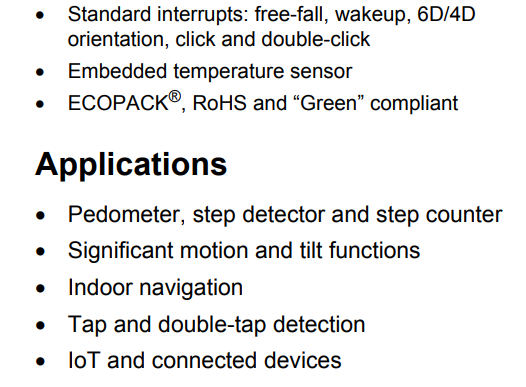
A 6-axis sensor would enable battery-powered device for motion input, which are not limited to the combination of input pattern that other methods have, and they are generally quite small and packed with many interesting features such as "free fall detection", " single tap", "double tap", "rise-hand wakeup" and etc. What's best? with a motion sensor like this, we can even run TinyML (Tensor Flow Lite for Microcontrollers) on BW16 Stamp!
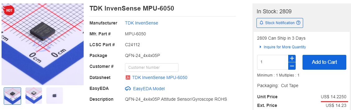
There are many 6-axis ICs, most popular one I guess is MPU-6050, which is good but a little expensive,
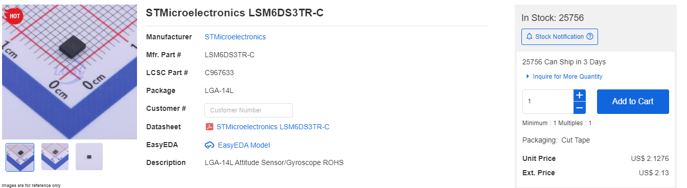
So I got my eye on another model,
LSM6DS3TR-C
from STMicroelectronics, it's only 1/7 of the price to MPU-6050, and it offers many addition features while still can attain a surprising 3 uA in idle mode!
So this really is a good fit for IoT device and BW16 Stamp!
I will be working on adding this IC into the PCB design and hopefully be able to get some result soon!
Stay tuned and happy making! ~~ :)
-
#9 The "perfect" version PCB finally arrives and works!
09/28/2022 at 11:03 • 0 commentsHooray! the latest "perfect" version has finally reached!
I have tested with a few Arduino Graphic Libraries, but so far the one works the best is Adafruit ST7735 Library, as it supports a number of LCD drivers and sizes and come with a feature-rich API set.
The biggest change to the previous version is the change of 160x80 footprint and correcting the wrong slide switch connection. However, this lesson have ot be learnt the hard way-- it took me weeks before I can get my hand on the latest PCB. So, despite all the goods in open-source community,
Always double check your code/parts after using any 3rd party libraries!
Anyway, I have ported the previous Wi-Fi Scanner project to this board, and let's watch a demo video together!
Here is the code used in the example,
#include <Adafruit_GFX.h> // Core graphics library #include <Adafruit_ST7735.h> // Hardware-specific library for ST7735 #include <Adafruit_ST7789.h> // Hardware-specific library for ST7789 #include <SPI.h> #include <WiFi.h> #define TFT_CS 9 #define TFT_RST 6 // Or set to -1 and connect to Arduino RESET pin #define TFT_DC 8 Adafruit_ST7735 tft = Adafruit_ST7735(TFT_CS, TFT_DC, TFT_RST); void setup(void) { Serial.begin(115200); Serial.print(F("Hello! ST77xx TFT Test")); // use this initializer (uncomment) if using a 0.96" 160x80 TFT: tft.initR(INITR_MINI160x80); // Init ST7735S mini display tft.setRotation(1); // retate 90 degrees tft.setCursor(3,2); Serial.println("test filling screen"); testFillScreen(); tft.fillScreen(ST77XX_BLACK); tft.invertDisplay(true); tft.setTextColor(ST77XX_BLUE); tft.setTextSize(1); tft.println("Ameba WiFi Scanner "); // check for the presence of the shield: if (WiFi.status() == WL_NO_SHIELD) { Serial.println("WiFi shield not present"); // don't continue: while (true); } // Print WiFi MAC address: printMacAddress(); // scan for existing networks: Serial.println("Scanning available networks..."); listNetworks(); Serial.println("done"); delay(1000); } void loop() { delay(100); } void testFillScreen() { tft.fillScreen(ST77XX_BLACK); delay(200); tft.fillScreen(ST77XX_RED); delay(200); tft.fillScreen(ST77XX_GREEN); delay(200); tft.fillScreen(ST77XX_BLUE); delay(200); tft.fillScreen(ST77XX_BLACK); delay(200); } void printMacAddress() { // the MAC address of your Wifi shield byte mac[6]; tft.setCursor(tft.getCursorX()+3, tft.getCursorY()); tft.setTextColor(ST77XX_GREEN); tft.setTextSize(1); tft.println("MAC Address:"); // print your MAC address: WiFi.macAddress(mac); Serial.print("MAC: "); Serial.print(mac[0], HEX); tft.print(mac[0], HEX); tft.print(":"); Serial.print(":"); Serial.print(mac[1], HEX); tft.print(mac[1], HEX); tft.print(":"); Serial.print(":"); Serial.print(mac[2], HEX); tft.print(mac[2], HEX); tft.print(":"); Serial.print(":"); Serial.print(mac[3], HEX); tft.print(mac[3], HEX); tft.print(":"); Serial.print(":"); Serial.print(mac[4], HEX); tft.print(mac[4], HEX); tft.print(":"); Serial.print(":"); Serial.println(mac[5], HEX); tft.println(mac[5], HEX); tft.println(); } void listNetworks() { // scan for nearby networks: Serial.println("** Scan Networks **"); int numSsid = WiFi.scanNetworks(); if (numSsid == -1) { Serial.println("Couldn't get a wifi connection"); while (true); } tft.fillScreen(ST77XX_BLACK); // print the list of networks seen: Serial.print("number of available networks:"); Serial.println(numSsid); tft.setCursor(3,2); tft.print("Number of WiFi found:"); tft.println(numSsid); tft.println(); // print the network number and name for each network found: for (int thisNet = 0; thisNet < numSsid; thisNet++) { Serial.print(thisNet); tft.print(thisNet); Serial.print(") "); tft.print(") "); Serial.print(WiFi.SSID(thisNet)); tft.print(WiFi.SSID(thisNet)); tft.print(" : "); Serial.print("\tSignal: "); Serial.print(WiFi.RSSI(thisNet)); tft.print(WiFi.RSSI(thisNet)); Serial.print(" dBm"); tft.print(" dBm"); Serial.print("\tEncryptionRaw: "); tft.print(", "); printEncryptionTypeEx(WiFi.encryptionTypeEx(thisNet)); Serial.print("\tEncryption: "); printEncryptionType(WiFi.encryptionType(thisNet)); } } void printEncryptionTypeEx(uint32_t thisType) { /* Arduino wifi api use encryption type to mapping to security type. * This function demonstrate how to get more richful information of security type. */ switch (thisType) { case SECURITY_OPEN: Serial.print("Open"); break; case SECURITY_WEP_PSK: Serial.print("WEP"); break; case SECURITY_WPA_TKIP_PSK: Serial.print("WPA TKIP"); break; case SECURITY_WPA_AES_PSK: Serial.print("WPA AES"); break; case SECURITY_WPA2_AES_PSK: Serial.print("WPA2 AES"); break; case SECURITY_WPA2_TKIP_PSK: Serial.print("WPA2 TKIP"); break; case SECURITY_WPA2_MIXED_PSK: Serial.print("WPA2 Mixed"); break; case SECURITY_WPA_WPA2_MIXED: Serial.print("WPA/WPA2 AES"); break; } } void printEncryptionType(int thisType) { // read the encryption type and print out the name: switch (thisType) { case ENC_TYPE_WEP: Serial.println("WEP"); tft.println("WEP"); break; case ENC_TYPE_TKIP: Serial.println("WPA"); tft.println("WPA"); break; case ENC_TYPE_CCMP: Serial.println("WPA2"); tft.println("WPA2"); break; case ENC_TYPE_NONE: Serial.println("None"); tft.println("None"); break; case ENC_TYPE_AUTO: Serial.println("Auto"); tft.println("Auto"); break; } } -
#8 New Design On-the-way
09/08/2022 at 08:30 • 0 commentsDue to a small flaw in the previous design, the LCD could not be soldered directly on the back of the BW16-Stamp, which was disappointing, this has taught me the important lesson once again -- don't take others' work as granted and perfect, always check and be careful, so that everybody's contribution to the open-source community won't go to waste.
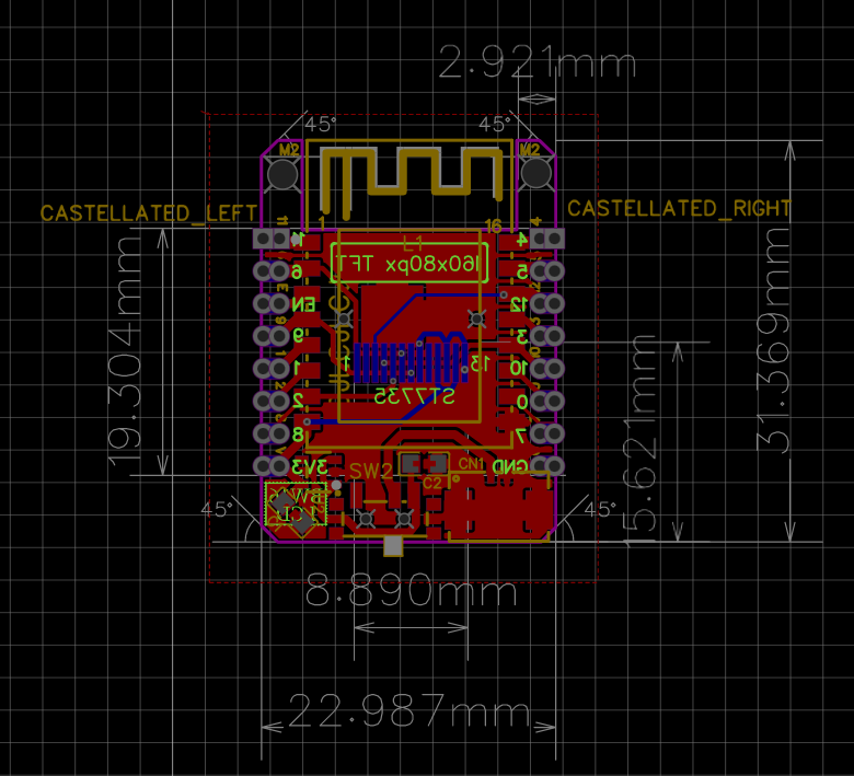
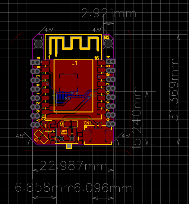
Anyway, this time around, I have re-design the board with correct footprint and symbol, measured all dimensions and angles to ensure it is correct this time.
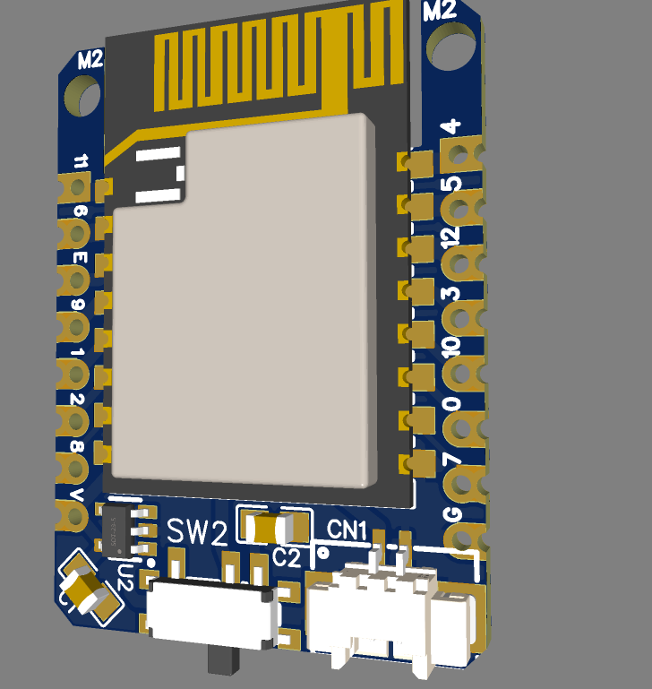
Schematic will be made public and available for download once I have received the PCB and confirm it is indeed working, but for now, we can have some previews,
---
So stay tuned and wait for my good news!
-
#7 BW16-LCD Arrived
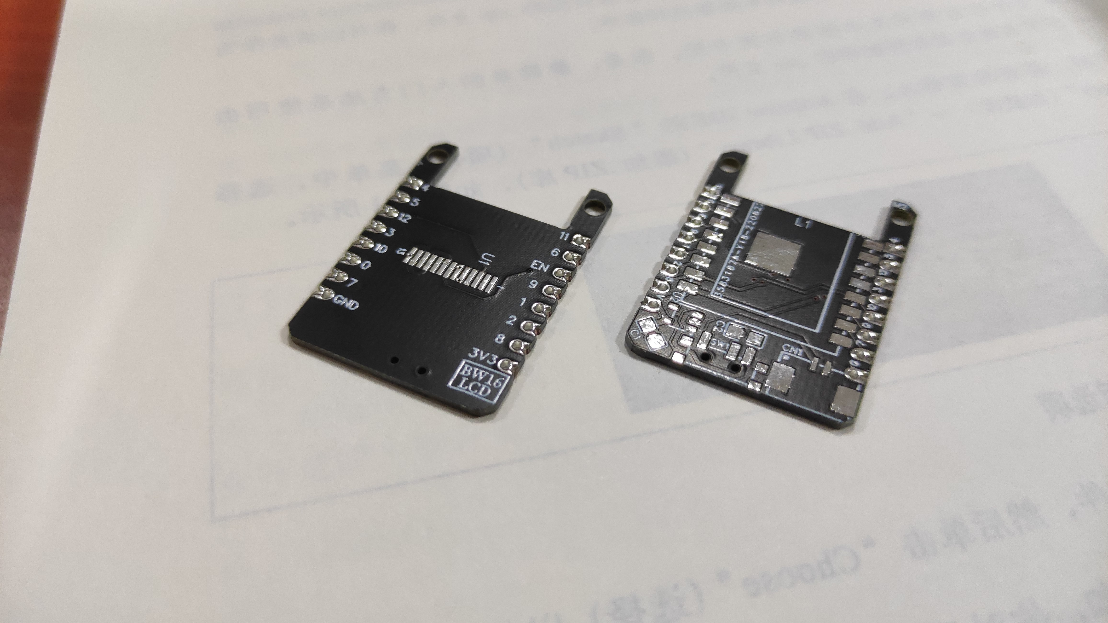
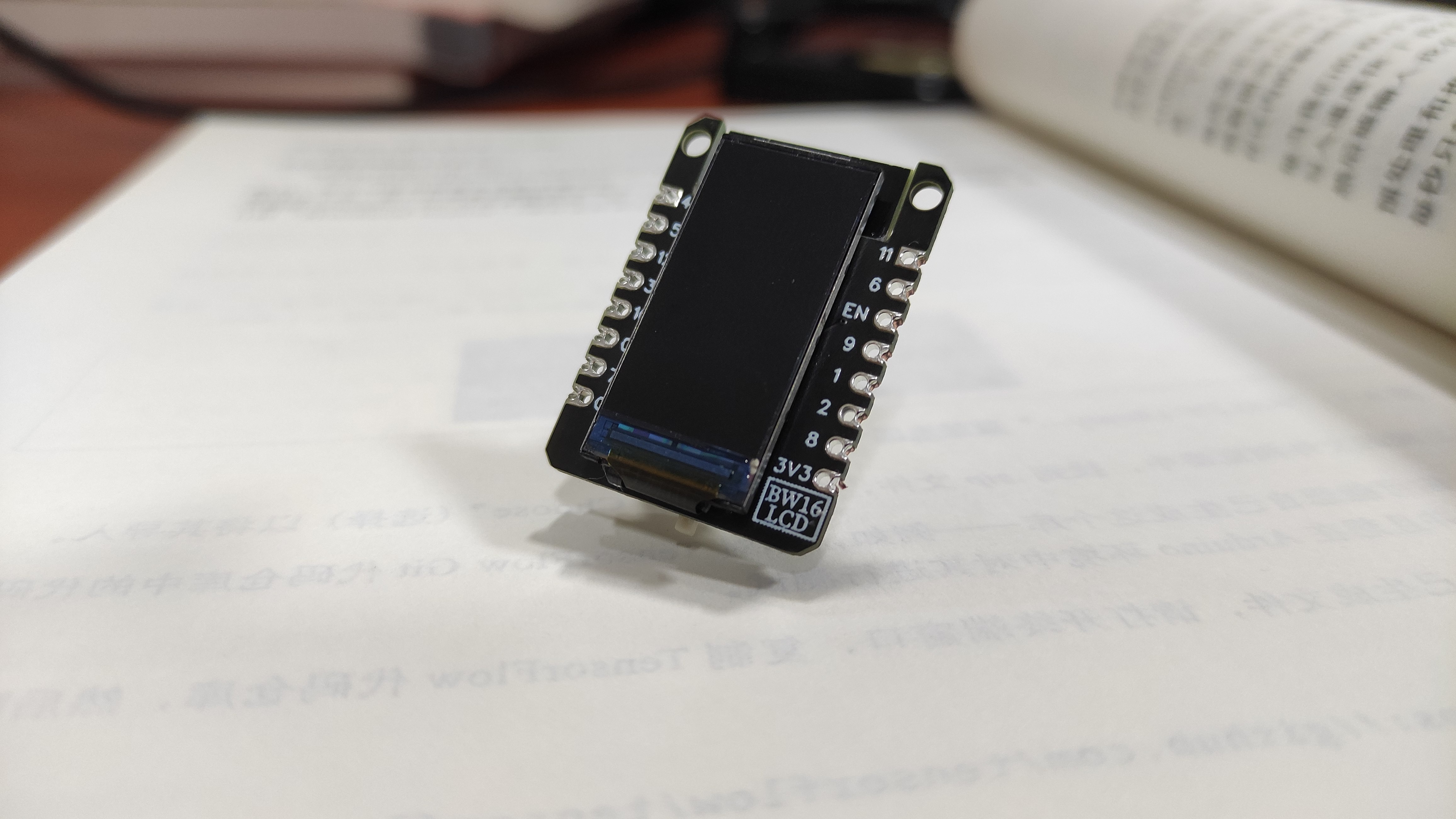
09/02/2022 at 10:09 • 0 commentsAfter 2 weeks, the PCB finally has arrived at my place, and this is how it looks in its complete form,
![]()
front and back (before soldering)
![]()
Front view
![]()
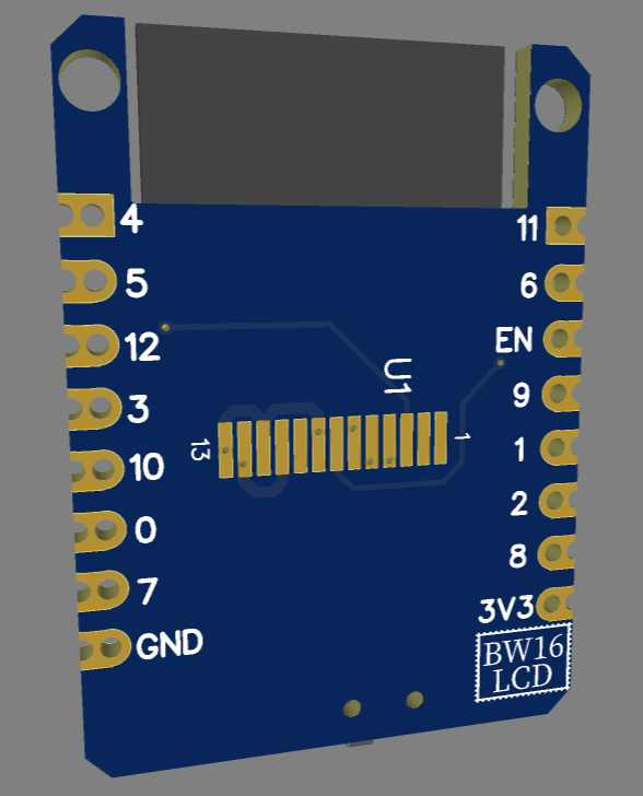
Back view
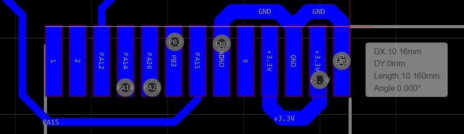
As you can see, it looks quite nice with the screen attached. However, I got the screen FPC connector pitch wrong and now it only works without the display T _ TThe width here is supposed to be 9mm wide, but it's 10.1mm now. This has taught me an important lesson -- when designing with 3rd party library/symbols, always check the dimension before use!!
For now I can use isolated copper wire to make the connections, but it will be a mess as compare to soldering onto the PCB.
Anyway, I will test with this version first, then fix the issues found and get a new version out, hopefully this time it will take less time~
-
#6 BW16 Stamp Upgrades | BW16-LCD
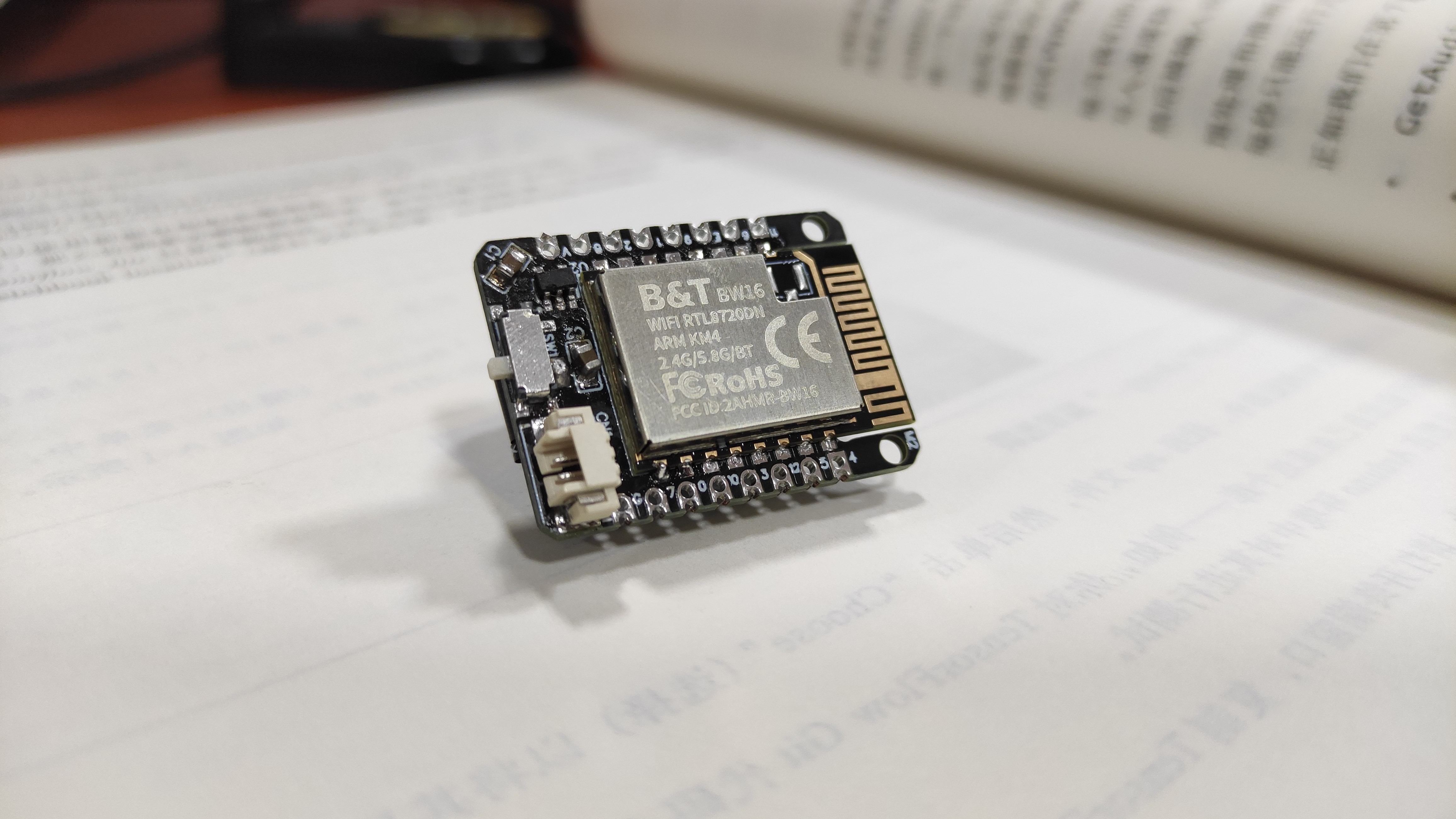
08/24/2022 at 06:07 • 0 commentsIn my previous project log, I have made BW16-Stamp to work with a baremetal & super tiny TFT color LCD display module( without a breakout board) with just a few wires and the result looks fantastic!
The circuit is super simple, no additional components needed! and the price for such tiny display is around $0.7/unit, super affordable! The performance of the display is decent enough for such small form factor with 0.96" in size and 160x80p resolution, graphics are vivid and rich, the packaging of the module is also clean and intuitive.
So I've decided to take this a bit further and implemented a major upgrade to the BW16-Stamp, which now becomes BW16-LCD!
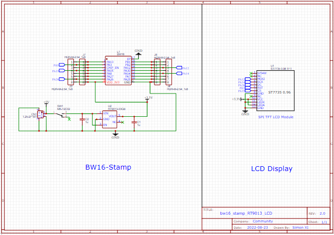
Schematics, PCB and 3D model
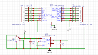
Here is the schematics,
And the PCB layout,
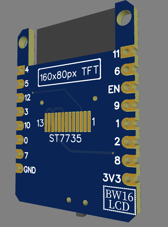
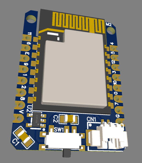
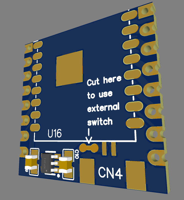
The 3D rendered model
Major changes
1. Add a 0.6A rated slide switch to control the power
I often found inserting and removing battery connector a big hassle, especially when the battery connector is next to other modules/connectors. So adding a slide switch solves the problem and cut down the power completely -- saving the quiescent current drawn from LDO when the whole module is in idle
2. Add ST7735 TFT Color LCD module solder pad
To eliminate the clutter of wires, we can put the soldering pad of the FPC cable from the display module on the back of the board, this way, we will have a more robust and neater connection between LCD and BW16-stamp
3. Add M2 mounting holes
For those who wish to make this into an accessory to carry around or mount onto another installation, 2 mounting holes can come handy
That's all I can share now, the PCB is on its way to my place, once I received it, I will make some project using it and share it here in another log, so stay tuned! -
#5 BW16 Stamp in action! | Ameba LCD
08/18/2022 at 02:36 • 0 commentsSince BW16 Stamp is so small yet very powerful, why not give it a nice display so that it can show beautiful graphics while still performing tasks as intended?
To add on a new element, we have to apply the same principle::
minimal components, easy, cheap and power-saving
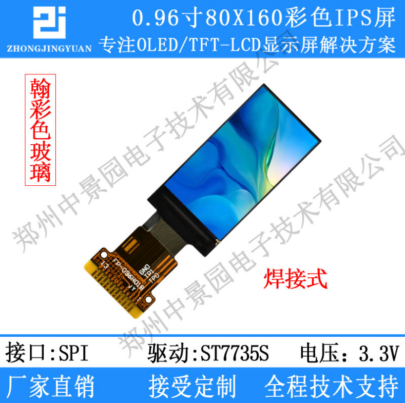
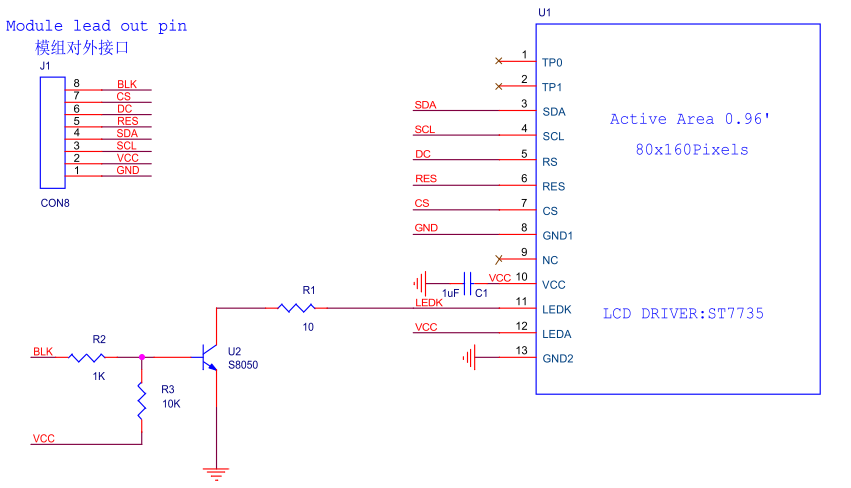
Therefore, this time, we chose a baremetal SPI TFT LCD display module with NO breakout board!
This is a SPI-interface 0.96" 1600x80 IPS Color TFT LCD Display that is driven by ST7735, it's super tiny and really cheap( ~$0.7)
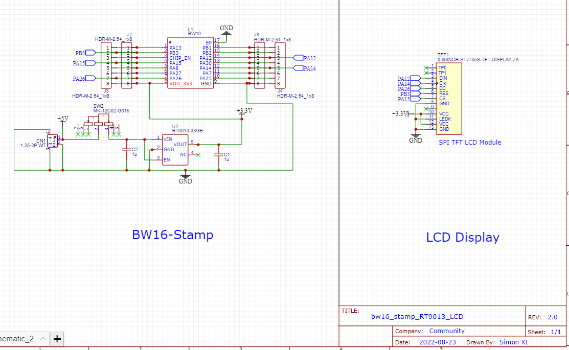
Surprisingly and contrary to common understanding, just buying the baremetal display is more than enough for a display project, as the display itself usually comes packed with necessary components and driver IC inside so users often only need to add minimal peripheral circuit in order to work with it. In this schematic, we can see that a common LCD display breakout board is of very simple design,
With a well-design MCU and a stable power source, you may ignore all the peripheral circuit and still have a decent display performance.
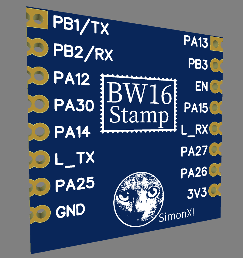
Here is how to connect to the BW16 Stamp,
TP0 ---- NC
TP1 ---- NC
SDA ---- PA12
SCL ---- PA14
RS(DC) ---- PA26
RES ---- PB3
CS ---- PA15
GND ---- GND
NC ---- NC
VCC ---- VCC
LEDK(cathode) ---- GND
LEDA(anode) ---- VCC
GND ---- GND
Now, we just need to flash the example code to test its performance, to do that, we can use the "Adafruit ST7735" library downloadable from Arduino IDE. Here is the modified example code for BW16 stamp,
/**************************************************************************
  This is a library for several Adafruit displays based on ST77* drivers.

  Works with the Adafruit 1.8" TFT Breakout w/SD card
    ----> http://www.adafruit.com/products/358
  The 1.8" TFT shield
    ----> https://www.adafruit.com/product/802
  The 1.44" TFT breakout
    ----> https://www.adafruit.com/product/2088
  The 1.14" TFT breakout
  ----> https://www.adafruit.com/product/4383
  The 1.3" TFT breakout
  ----> https://www.adafruit.com/product/4313
  The 1.54" TFT breakout
    ----> https://www.adafruit.com/product/3787
  The 1.69" TFT breakout
    ----> https://www.adafruit.com/product/5206
  The 2.0" TFT breakout
    ----> https://www.adafruit.com/product/4311
  as well as Adafruit raw 1.8" TFT display
    ----> http://www.adafruit.com/products/618

  Check out the links above for our tutorials and wiring diagrams.
  These displays use SPI to communicate, 4 or 5 pins are required to
  interface (RST is optional).

  Adafruit invests time and resources providing this open source code,
  please support Adafruit and open-source hardware by purchasing
  products from Adafruit!

  Written by Limor Fried/Ladyada for Adafruit Industries.
  MIT license, all text above must be included in any redistribution
 **************************************************************************/

#include <Adafruit_GFX.h>    // Core graphics library
#include <Adafruit_ST7735.h> // Hardware-specific library for ST7735
#include <Adafruit_ST7789.h> // Hardware-specific library for ST7789
#include <SPI.h>

#if defined(ARDUINO_FEATHER_ESP32) // Feather Huzzah32
  #define TFT_CS         14
  #define TFT_RST        15
  #define TFT_DC         32

#elif defined(ESP8266)
  #define TFT_CS         4
  #define TFT_RST        16
  #define TFT_DC         5

#else
  // For the breakout board, you can use any 2 or 3 pins.
  // These pins will also work for the 1.8" TFT shield.
  #define TFT_CS         9
  #define TFT_RST        6 // Or set to -1 and connect to Arduino RESET pin
  #define TFT_DC         8
#endif

// OPTION 1 (recommended) is to use the HARDWARE SPI pins, which are unique
// to each board and not reassignable. For Arduino Uno: MOSI = pin 11 and
// SCLK = pin 13. This is the fastest mode of operation and is required if
// using the breakout board's microSD card.

// For 1.44" and 1.8" TFT with ST7735 use:
Adafruit_ST7735 tft = Adafruit_ST7735(TFT_CS, TFT_DC, TFT_RST);

// For 1.14", 1.3", 1.54", 1.69", and 2.0" TFT with ST7789:
//Adafruit_ST7789 tft = Adafruit_ST7789(TFT_CS, TFT_DC, TFT_RST);


// OPTION 2 lets you interface the display using ANY TWO or THREE PINS,
// tradeoff being that performance is not as fast as hardware SPI above.
//#define TFT_MOSI 11  // Data out
//#define TFT_SCLK 13  // Clock out

// For ST7735-based displays, we will use this call
//Adafruit_ST7735 tft = Adafruit_ST7735(TFT_CS, TFT_DC, TFT_MOSI, TFT_SCLK, TFT_RST);

// OR for the ST7789-based displays, we will use this call
//Adafruit_ST7789 tft = Adafruit_ST7789(TFT_CS, TFT_DC, TFT_MOSI, TFT_SCLK, TFT_RST);


float p = 3.1415926;

void setup(void) {
  Serial.begin(115200);
  Serial.print(F("Hello! ST77xx TFT Test"));

  // Use this initializer if using a 1.8" TFT screen:
  //tft.initR(INITR_BLACKTAB);      // Init ST7735S chip, black tab

  // OR use this initializer if using a 1.8" TFT screen with offset such as WaveShare:
  // tft.initR(INITR_GREENTAB);      // Init ST7735S chip, green tab

  // OR use this initializer (uncomment) if using a 1.44" TFT:
  // tft.initR(INITR_144GREENTAB); // Init ST7735R chip, green tab

  // OR use this initializer (uncomment) if using a 0.96" 160x80 TFT:
  tft.initR(INITR_MINI160x80);  // Init ST7735S mini display

  // OR use this initializer (uncomment) if using a 1.3" or 1.54" 240x240 TFT:
  //tft.init(240, 240);           // Init ST7789 240x240

  // OR use this initializer (uncomment) if using a 1.69" 280x240 TFT:
  //tft.init(240, 280);           // Init ST7789 280x240

  // OR use this initializer (uncomment) if using a 2.0" 320x240 TFT:
  //tft.init(240, 320);           // Init ST7789 320x240

  // OR use this initializer (uncomment) if using a 1.14" 240x135 TFT:
  //tft.init(135, 240);           // Init ST7789 240x135

  // OR use this initializer (uncomment) if using a 1.47" 172x320 TFT:
  //tft.init(172, 320);           // Init ST7789 172x320

  // SPI speed defaults to SPI_DEFAULT_FREQ defined in the library, you can override it here
  // Note that speed allowable depends on chip and quality of wiring, if you go too fast, you
  // may end up with a black screen some times, or all the time.
  //tft.setSPISpeed(40000000);

  Serial.println(F("Initialized"));

  uint16_t time = millis();
  tft.fillScreen(ST77XX_BLACK);
  time = millis() - time;

  Serial.println(time, DEC);
  delay(500);

  // large block of text
  tft.fillScreen(ST77XX_BLACK);
  testdrawtext("Lorem ipsum dolor sit amet, consectetur adipiscing elit. Curabitur adipiscing ante sed nibh tincidunt feugiat. Maecenas enim massa, fringilla sed malesuada et, malesuada sit amet turpis. Sed porttitor neque ut ante pretium vitae malesuada nunc bibendum. Nullam aliquet ultrices massa eu hendrerit. Ut sed nisi lorem. In vestibulum purus a tortor imperdiet posuere. ", ST77XX_WHITE);
  delay(1000);

  // tft print function!
  tftPrintTest();
  delay(4000);

  // a single pixel
  tft.drawPixel(tft.width()/2, tft.height()/2, ST77XX_GREEN);
  delay(500);

  // line draw test
  testlines(ST77XX_YELLOW);
  delay(500);

  // optimized lines
  testfastlines(ST77XX_RED, ST77XX_BLUE);
  delay(500);

  testdrawrects(ST77XX_GREEN);
  delay(500);

  testfillrects(ST77XX_YELLOW, ST77XX_MAGENTA);
  delay(500);

  tft.fillScreen(ST77XX_BLACK);
  testfillcircles(10, ST77XX_BLUE);
  testdrawcircles(10, ST77XX_WHITE);
  delay(500);

  testroundrects();
  delay(500);

  testtriangles();
  delay(500);

  mediabuttons();
  delay(500);

  Serial.println("done");
  delay(1000);
}

void loop() {
  tft.invertDisplay(true);
  delay(500);
  tft.invertDisplay(false);
  delay(500);
}

void testlines(uint16_t color) {
  tft.fillScreen(ST77XX_BLACK);
  for (int16_t x=0; x < tft.width(); x+=6) {
    tft.drawLine(0, 0, x, tft.height()-1, color);
    delay(0);
  }
  for (int16_t y=0; y < tft.height(); y+=6) {
    tft.drawLine(0, 0, tft.width()-1, y, color);
    delay(0);
  }

  tft.fillScreen(ST77XX_BLACK);
  for (int16_t x=0; x < tft.width(); x+=6) {
    tft.drawLine(tft.width()-1, 0, x, tft.height()-1, color);
    delay(0);
  }
  for (int16_t y=0; y < tft.height(); y+=6) {
    tft.drawLine(tft.width()-1, 0, 0, y, color);
    delay(0);
  }

  tft.fillScreen(ST77XX_BLACK);
  for (int16_t x=0; x < tft.width(); x+=6) {
    tft.drawLine(0, tft.height()-1, x, 0, color);
    delay(0);
  }
  for (int16_t y=0; y < tft.height(); y+=6) {
    tft.drawLine(0, tft.height()-1, tft.width()-1, y, color);
    delay(0);
  }

  tft.fillScreen(ST77XX_BLACK);
  for (int16_t x=0; x < tft.width(); x+=6) {
    tft.drawLine(tft.width()-1, tft.height()-1, x, 0, color);
    delay(0);
  }
  for (int16_t y=0; y < tft.height(); y+=6) {
    tft.drawLine(tft.width()-1, tft.height()-1, 0, y, color);
    delay(0);
  }
}

void testdrawtext(char *text, uint16_t color) {
  tft.setCursor(0, 0);
  tft.setTextColor(color);
  tft.setTextWrap(true);
  tft.print(text);
}

void testfastlines(uint16_t color1, uint16_t color2) {
  tft.fillScreen(ST77XX_BLACK);
  for (int16_t y=0; y < tft.height(); y+=5) {
    tft.drawFastHLine(0, y, tft.width(), color1);
  }
  for (int16_t x=0; x < tft.width(); x+=5) {
    tft.drawFastVLine(x, 0, tft.height(), color2);
  }
}

void testdrawrects(uint16_t color) {
  tft.fillScreen(ST77XX_BLACK);
  for (int16_t x=0; x < tft.width(); x+=6) {
    tft.drawRect(tft.width()/2 -x/2, tft.height()/2 -x/2 , x, x, color);
  }
}

void testfillrects(uint16_t color1, uint16_t color2) {
  tft.fillScreen(ST77XX_BLACK);
  for (int16_t x=tft.width()-1; x > 6; x-=6) {
    tft.fillRect(tft.width()/2 -x/2, tft.height()/2 -x/2 , x, x, color1);
    tft.drawRect(tft.width()/2 -x/2, tft.height()/2 -x/2 , x, x, color2);
  }
}

void testfillcircles(uint8_t radius, uint16_t color) {
  for (int16_t x=radius; x < tft.width(); x+=radius*2) {
    for (int16_t y=radius; y < tft.height(); y+=radius*2) {
      tft.fillCircle(x, y, radius, color);
    }
  }
}

void testdrawcircles(uint8_t radius, uint16_t color) {
  for (int16_t x=0; x < tft.width()+radius; x+=radius*2) {
    for (int16_t y=0; y < tft.height()+radius; y+=radius*2) {
      tft.drawCircle(x, y, radius, color);
    }
  }
}

void testtriangles() {
  tft.fillScreen(ST77XX_BLACK);
  uint16_t color = 0xF800;
  int t;
  int w = tft.width()/2;
  int x = tft.height()-1;
  int y = 0;
  int z = tft.width();
  for(t = 0 ; t <= 15; t++) {
    tft.drawTriangle(w, y, y, x, z, x, color);
    x-=4;
    y+=4;
    z-=4;
    color+=100;
  }
}

void testroundrects() {
  tft.fillScreen(ST77XX_BLACK);
  uint16_t color = 100;
  int i;
  int t;
  for(t = 0 ; t <= 4; t+=1) {
    int x = 0;
    int y = 0;
    int w = tft.width()-2;
    int h = tft.height()-2;
    for(i = 0 ; i <= 16; i+=1) {
      tft.drawRoundRect(x, y, w, h, 5, color);
      x+=2;
      y+=3;
      w-=4;
      h-=6;
      color+=1100;
    }
    color+=100;
  }
}

void tftPrintTest() {
  tft.setTextWrap(false);
  tft.fillScreen(ST77XX_BLACK);
  tft.setCursor(0, 30);
  tft.setTextColor(ST77XX_RED);
  tft.setTextSize(1);
  tft.println("Hello World!");
  tft.setTextColor(ST77XX_YELLOW);
  tft.setTextSize(2);
  tft.println("Hello World!");
  tft.setTextColor(ST77XX_GREEN);
  tft.setTextSize(3);
  tft.println("Hello World!");
  tft.setTextColor(ST77XX_BLUE);
  tft.setTextSize(4);
  tft.print(1234.567);
  delay(1500);
  tft.setCursor(0, 0);
  tft.fillScreen(ST77XX_BLACK);
  tft.setTextColor(ST77XX_WHITE);
  tft.setTextSize(0);
  tft.println("Hello World!");
  tft.setTextSize(1);
  tft.setTextColor(ST77XX_GREEN);
  tft.print(p, 6);
  tft.println(" Want pi?");
  tft.println(" ");
  tft.print(8675309, HEX); // print 8,675,309 out in HEX!
  tft.println(" Print HEX!");
  tft.println(" ");
  tft.setTextColor(ST77XX_WHITE);
  tft.println("Sketch has been");
  tft.println("running for: ");
  tft.setTextColor(ST77XX_MAGENTA);
  tft.print(millis() / 1000);
  tft.setTextColor(ST77XX_WHITE);
  tft.print(" seconds.");
}

void mediabuttons() {
  // play
  tft.fillScreen(ST77XX_BLACK);
  tft.fillRoundRect(25, 10, 78, 60, 8, ST77XX_WHITE);
  tft.fillTriangle(42, 20, 42, 60, 90, 40, ST77XX_RED);
  delay(500);
  // pause
  tft.fillRoundRect(25, 90, 78, 60, 8, ST77XX_WHITE);
  tft.fillRoundRect(39, 98, 20, 45, 5, ST77XX_GREEN);
  tft.fillRoundRect(69, 98, 20, 45, 5, ST77XX_GREEN);
  delay(500);
  // play color
  tft.fillTriangle(42, 20, 42, 60, 90, 40, ST77XX_BLUE);
  delay(50);
  // pause color
  tft.fillRoundRect(39, 98, 20, 45, 5, ST77XX_RED);
  tft.fillRoundRect(69, 98, 20, 45, 5, ST77XX_RED);
  // play color
  tft.fillTriangle(42, 20, 42, 60, 90, 40, ST77XX_GREEN);
}
Done!
Let's watch a demo together!
-
#4 BW16-Stamp in Action! | Ameba Neo
06/23/2022 at 07:50 • 0 commentsBW16-Stamp has been designed for a while, now it's time to see it in action, let's watch a demo video
In this demo, you will notice there are a few interesting new features added,
1. Auto Flash Enabled
With the community contribution from jojoling, and some simple circuitry on the breadboard, you can now auto-flash the BW16-Stamp with a single click of button( with Arduino IDE). This is very handy feature, as in the pursuit of a minimalist design, adding components like buttons and etc is gonna make the stamp much bigger and also more complex( you have to recall the button pressing sequence to get it into UART downlaod mode), thus adding this feature will make programming BW16-Stamp a no brainer.
2. The side-mounted battery connector
The side-mounted battery connector makes the entire profile much cleaner and thinner, which means higher possibilities to embed a project made from BW16-Stamp into small enclosure or 3D printed case
3. The 2.54 Pitch Castellated Holes
These holes work really well with breadboard, even for a temperory fixing with male pin headers. This also enable it to work with other breadboard-friendly compponents such as the Neopixel LED shown in the video, soldering the LED onto the stamp is truly a bliss.
-
#3 [BW16 Stamp] Version 2 is finally out
05/26/2022 at 09:50 • 0 commentsI have designed a second version of the Ameba Stamp and have renamed it to "BW16 Stamp" which is more intuitive to most makers.
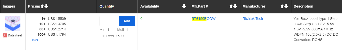
In the previous log, I have mentioned that I would like to replace the LDO MAS1117 with DCDC convertor to save power from the relatively high quiescent current (2mA) that AMS1117 draws, but after searching for the parts and availablity, it appears that the global chip shortage still persists 😅
Plus, replacing with DCDC convertor will also introduce many more passive components as compared to LDO, this will result in bigger PCB layout, higher price point and more complex PCB design.
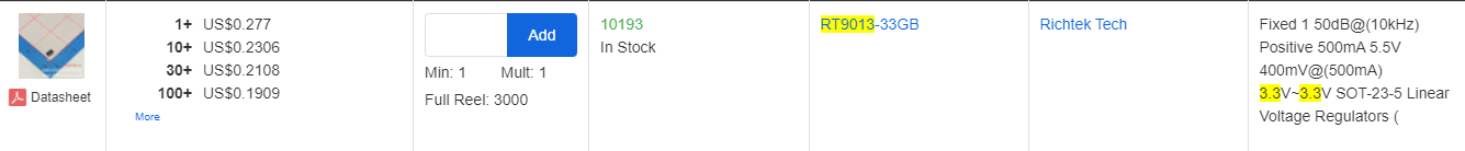
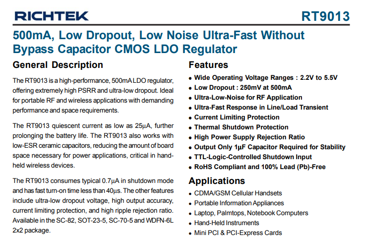
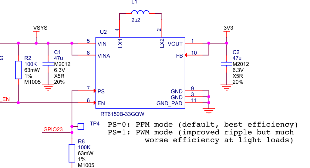
Therefore, I have done some research and located a new LDO -- RT9013, it works similar to AMS1117 LDO, but it requires much less passive components (only 2 de-coupling capacitors) and much much less quiescent current (≈25uA), which is about 80 times less than AMS1117 LDO. The footprint of this IC is also much smaller than both the DCDC convertor and AMS1117, the price and availability is also a big bonus,
The only downside however, is that it is only able to deliver 500mA power at max (AMS1117 delivers 1A), but in the 1 Ohm Resistor Energy Meter project, we have measure and observed that the max instantaneous current drawn from BW16 is around 200mA, so 500mA is good enough for many low power profile projects.
The schematic is completed
This is how it looks in 3D rendering,
The second version will be open sourced later, so stay tuned for more updates~
-
#2 Improvements for 2nd edition
02/11/2022 at 03:25 • 0 comments- Increase the board width to let the board fit into bread board more easily
- Increase the tolerance for the outer half holes so that the machining process will not damage too much of the holes' copper coating
- AMS1117 has too high of the static current drawn and only able to regulate the power when the batter is above 3.3 V, so I am going to replace with the DCDC power IC from RPI Pico as it can handle both high and low input voltage
BW16 Stamp - Tiny 5GHz WiFi Dev Board
Super compact functional 5G Hz WiFi MCU in stamp size with power circuit, work out of the box
 This is good when you have many GPIO available, but for BW16 Stamp, our GPIO resources are also limited, so taking up 5 GPIO is a little to much.
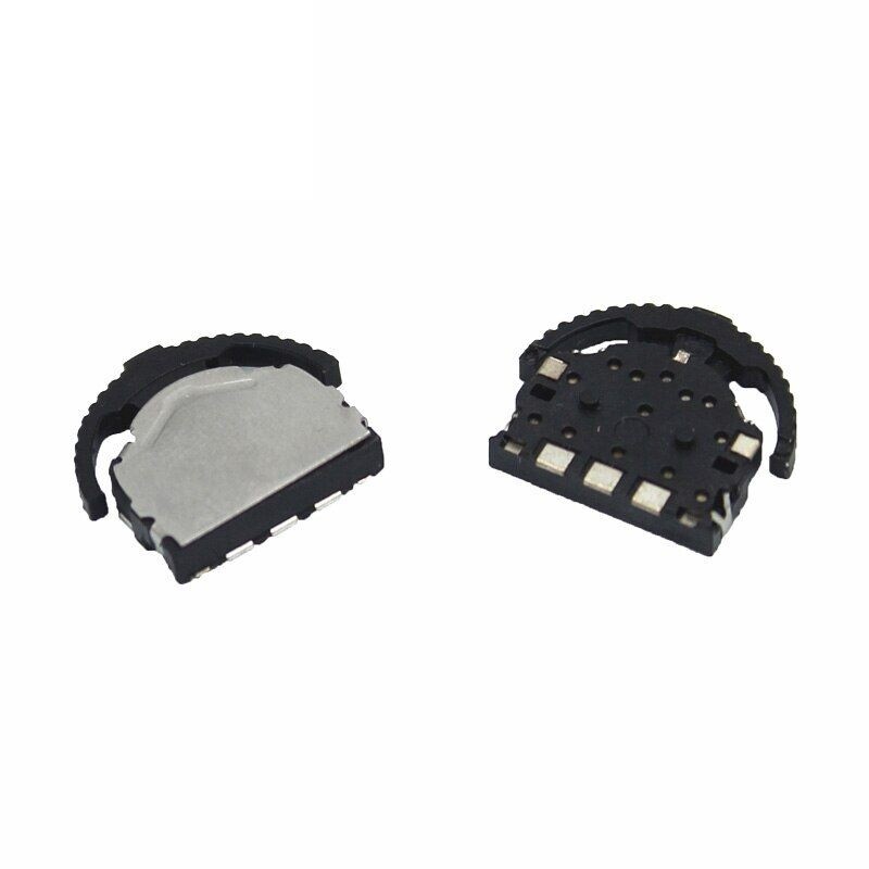 This is almost perfect, as it only need 3 GPIOs, but its size is still too big for our BW16 Stamp...