 Epsilon
-
Post-Implementation Memory Updates.
06/18/2023 at 13:55 • 0 comments -
Bringing up the SD-Card Controller and File System.
05/12/2023 at 13:05 • 0 commentsI added an SD-Card Controller and File System to BoxLambda:
https://epsilon537.github.io/boxlambda/sd-and-fs-bring-up/
![]()
-
Integrating VERA
04/20/2023 at 12:25 • 0 commentsI integrated the VERA Versatile Embedded Retro Adapter into the BoxLambda SoC. The Blog post below discusses the changes I made to the VERA core to interface it with a 32-bit system.
https://epsilon537.github.io/boxlambda/ ... ting-vera/
![]()
-
Building Software and Gateware with CMake and Bender.
02/14/2023 at 21:39 • 0 commentsRecap
This is a summary of the current state of affairs for BoxLambda. We have:
- An Ibex RISC-V core, a Wishbone shared bus, a Debug Core, internal memory, a timer, two GPIO ports, and a UART core.
- A Picolibc-based standard C environment for software running on the Ibex RISC-V core.
- Test builds running on Arty-A7-35T and Verilator.
- Automated testing on Verilator.
- OpenOCD-based Debug Access, both on FPGA and Verilator.
- A Linux GNU Makefile and Bender-based RTL build system.
- DDR3 external memory access through the Litex Memory Controller.
The Case for CMake
Around the time I integrated Picolibc into BoxLambda it became clear that I needed to invest a bit more energy in BoxLambda’s build system. The build system was based on a simple set of GNU Make rules and Bender manifests. It worked reasonably well for Verilator and FPGA synthesis, but there were a few limitations that were starting to hurt. Specifically, I wanted to add the following features to the build system:
- Proper dependency tracking for software: The old build system used forced build rules. Every software build was a full rebuild. The improved build system should use incremental builds with proper dependency tracking from memory files to executables, to libraries, and sources.
- Proper dependency tracking for RTL: Implementation and bitstream generation depends on synthesis. Synthesis depends on HDL sources, constraints files, and memory files. Memory files depend on software.
- Out-of-Tree build trees: Out-of-Tree build trees are way more convenient than In-Tree build trees. You can create as many of them as you want, they’re easy to remove when you no longer need them, and the derived objects don’t clutter up your source tree.
- Support for build options: I want to be able to specify whether the build tree is to be used for simulation builds, or for FPGA synthesis.
- Support for different FPGA targets: Arty-A7-35T and Arty-A7-100T to begin with.
I thought this would be a good opportunity to try out Meson, a modern build system generator with a clean, elegant python-like syntax. The Meson experiment came to a halt pretty quickly, however. I just couldn’t get my head around the fact that the Meson DSL does not include functions or macros. I ended up with a bunch of virtually identical meson.build files because I didn’t have a way to abstract common patterns. You can take a look at BoxLambda’s meson branch if you’re interested.
I decided to switch over to CMake. Compared to Meson, CMake has a more cluttered, messy syntax, but it is more flexible. It has functions, macros, and all the other goodies you can expect of a build system generator:
- Easy dependency tracking.
- Support for Out-of-Tree builds.
- Support for build options.
- Support for automated testing.
- Configure-Time source code generation.
This is the first time I’m using a build system generator. I always got by with GNU Make itself. Now that I that I tried CMake, I have to say that I like it a lot. It’s almost like going from assembly language to C. I probably could have implemented all the build system features I wanted directly in GNU Make, but it’s so much easier in CMake.
Sidenote: Gateware
I first encountered the term Gateware in the LiteX project.
I think the term covers its meaning very well and it’s the perfect counterpart for software. I’ll be using it from here on out.
The Directory Structure
<BoxLambda Root Directory>
├── boxlambda_setup.sh
├── CMakeLists.txt
├── sub/
│   └── <git submodules>
├── gw/
│   ├── CMakeLists.txt
│   ├── components/
│   │   ├── CMakeLists.txt
│   │   ├── wbuart32/
│   │   │   ├── rtl/
│   │   │   ├── CMakeLists.txt
│   │   │   └── Bender.yml
│   │   └── <other gw component directories>
│   └── projects/
│       ├── CMakeLists.txt
│       ├── ddr_test/
│       │   ├── constr/
│       │   ├── rtl/
│       │   ├── sim/
│       │   ├── CMakeLists.txt
│       │   └── Bender.yml
│       └── <other gw project directories>
├── sw/
│   ├── CMakeLists.txt
│   ├── components/
│   │   ├── CMakeLists.txt
│   │   └── <sw component directories>
│   └── projects/
│       ├── CMakeLists.txt
│       ├── ddr_test/
│       │   ├── CMakeLists.txt
│       │   └── <ddr_test sources>
│       └── <other sw project directories>
└── build/    ├── sim/    ├── arty-a7-35/	    └── arty-a7-100/
I made some changes to BoxLambda’s directory structure:
- I separated the software tree (sw/) from the gateware tree (gw/).
- The build trees (build/) are separate from the sw and gw source trees
The build trees are CMake build trees generated by the boxlambda_setup.sh script. As you can see in the tree diagram above, the script generates three build trees: one for simulation, one for the Arty-A7-35T, and one for the Arty A7-100T. The build trees are not under version control.
Building Gateware
Assuming all Prerequisites are installed, navigate to the build tree of choice and type:
make <gw component or project name>_<action>
where action is one of the following:
- lint: Lint-check the given gateware component or project.
- sim: Build the Verilator simulation model (Vmodel) of the given gateware project. This action only exists in the sim/ build tree.
- synth: Synthesize the given gateware component or project. This action only exists in the arty-a7 build trees.
- impl: Implement the given gateware project and generate its bitstream. This action only exists in the arty-a7 build trees.
- load: Load the gateware project’s bitstream file onto the connected target. This action only exists in the arty-a7 build trees.
Some examples:
cd <boxlambda_root_dir>/build/sim && make ddr_test_sim
cd <boxlambda_root_dir>/build/arty-a7-35 && make hello_world_synth
cd <boxlambda_root_dir>/build/arty-a7-100 && make hello_dbg_impl && make hello_dbg_load
The build directory tree mimics the source tree. When a build has been completed, a gateware project’s Verilator model or the Vivado project files can be found under that project’s directory. E.g.:
$ cd build/arty-a7-35/gw/projects/hello_world
$ make hello_world_synth
...
$ ls
CMakeFiles           hello_world.constraints_file_list  project.cache          project.runs    syn_util.rpt
CTestTestfile.cmake  hello_world.mem_file_list          project.dep            project.xpr
Makefile             hello_world.vivado_sources         project.hw             spram.mem
cmake_install.cmake  hello_world.vivado_sources.dep     project.ip_user_files  syn_timing.rpt
What happens when you run make hello_world_synth
When you run make hello_world_synth, the following happens:
- Make determines if (re)synthesis is needed. If synthesis is up-to-date, no further action is taken.
- Make runs a bender script command on the bender.yml file in the gw/projects/hello_world/ directory. The bender script command is wrapped in the scripts/bender_gen_vivado_source.sh shell script.
- The bender script command processes that bender.yml manifest, as well as the bender.yml manifests of any dependent components.
- The bender script command emits a list of all the HDL sources that make up the project.
- Similarly, the scripts/bender_gen_constraints_file_list.sh and scripts/bender_gen_mem_file_list.sh emits the .xdc constraints and .mem memory files for the project.
- Make feeds these file lists into a vivado_create_project.tcl script.
- The vivado_create_project.tcl script creates a Vivado project.
- Make kicks off the vivado_synth.tcl script which opens the Vivado project and starts synthesis.
When you run make hello_world_impl, the following happens:
- Make determines if (re)implementation and bitstream generation is needed. If the bitstream file is up-to-date, no further action is taken. Make will also run the hello_world_synth rule above because it’s a dependency of hello_world_impl.
- Make kicks off the vivado_impl.tcl script which opens the Vivado project, picks up the synthesis checkpoint, and starts implementation.
See the BoxLambda documentation Bender section of for more info on how BoxLambda uses Bender.
Building Software
The software corresponding with a gateware project automatically gets compiled, converted to a memory file, and included in the gateware project as part of the build process. Software projects can also be built independently. From the build directory just type:
make <sw project name>. For example:$ cd sim/sw/projects/hello_world/ $ make hello_world ... $ ls CMakeFiles Makefile hello_world hello_world.map CTestTestfile.cmake cmake_install.cmake hello_world.hex hello_world.mem
Make All, Clean, and Regen
make allwill lint check and build ‘impl’ all gateware projects.make cleanin a build tree will remove all the generated files that the build system is aware of. The generated files the build system is not aware of, e.g. synthesis utilization report files, will not be removed, however. If you want to go back to a completely clean build tree, typemake regenfrom the build directory. This command will completely remove and regenerate the build tree.Creating additional build trees
You can easily create additional build trees from the BoxLambda root directory with the following command:
cmake --preset=sim|arty-a7-35|arty-a7-100 -B <build directory>
For example:
cmake --preset=sim -B build/sim2
Running Regression Tests
CMake comes with a regression test framework called Ctest. BoxLambda regression tests are only defined in a simulation build tree. To see a list of available test cases, you need to first build everything and then run a
ctest -Ncommand to list the test cases:cd <boxlambda root dir>/build/sim make all ctest -N
You should see something like this:
Test project /home/epsilon/work/boxlambda/build/sim2  Test #1: hello_world_test  Test #2: hello_dbg_test  Test #3: picolibc_test_test  Test #4: ddr_test_test

Total Tests: 4
To run a specific test, run the following command from the build directory:
ctest -I <test number>
To run all tests, just run the ctest command without any parameters.
The CMakeLists
The build system consists of a tree of CMakeLists.txt files: The top-level CMakeLists.txt adds the gw/ and sw/ subdirectories. The CMakeLists.txt files in those subdirectories add the components/ and projects/ subdirectories, etc., down to the individual GW and SW component and project directories.
A Gateware Component CMakeList
The build instructions for a gateware component are grouped into one CMake function: gw_component_rules(). A GW component-level CMakeLists.txt file contains just a call to this function, passing in the expected parameters:
gw_component_rules( TOP_MODULE <top module name> COMPONENT_NAME <component name> )
For example:
gw_component_rules( TOP_MODULE wb_wbuart_wrap_wrap COMPONENT_NAME wbuart32 )
The component’s sources, definitions, and dependencies are still defined in its bender.yml manifest. The CMake build system interfaces with Bender through a set of scripts to extract the necessary info and pass it on to Vivado or Verilator.
See the BoxLambda documentation Bender section of for more info on how BoxLambda uses Bender.
A Gateware Project CMakeList
The build instructions for a gateware project are also grouped into a CMake function: gw_project_rules(). This function has a few additional arguments compared to its component counterpart. A typical GW project CMakeLists.txt file looks like this:
gw_project_rules(    TOP_MODULE <top module name>    PROJECT_NAME <project name>    MEM_FILE_TARGET <sw project name>    MEM_FILE_OUT <name of memory file expected by the SoC build. Currently, all project builds use spram.mem.>    VERILATOR_CPP_FLAGS <Verilator CPP flags, e.g. include paths>    VERILATOR_LD_FLAGS <Verilator link flags, e.g. -lncurses>
)

#Add testcase.
add_test(NAME <test name>    COMMAND <test command>    WORKING_DIRECTORY ${CMAKE_CURRENT_BINARY_DIR}
)
For example:
gw_project_rules(    TOP_MODULE ibex_soc    PROJECT_NAME hello_world    MEM_FILE_TARGET hello_world    MEM_FILE_OUT spram.mem    VERILATOR_CPP_FLAGS "-I${PROJECT_SOURCE_DIR}/sub/wbuart32/bench/cpp/"    VERILATOR_LD_FLAGS "-lncurses"
)

add_test(NAME hello_world_test    COMMAND ./Vmodel    WORKING_DIRECTORY ${CMAKE_CURRENT_BINARY_DIR}
)
As is the case for GW components, the project’s sources, definitions, dependencies, and constraint files are defined in its bender.yml manifest. The reference to the SW project delivering the memory file is not defined in the Bender manifest, however. The SW project name is passed in as the MEM_FILE_TARGET parameter in the gw_project_rules() call.
Any test cases are also added to the project’s CMakeLists.txt file.
Software Build Structure
CMake is designed to build software. The necessary functions for creating libraries, executables, etc. are predefined. The only custom function added to the software CMakeLists tree is link_internal_create_mem_file(). This function implements the necessary instructions to link the given executable against the BoxLambda internal memory map and generate a memory file, to be used by the GW part of the build system.
A typical SW project CMakeLists.txt file looks like this:
add_executable(hello_world    EXCLUDE_FROM_ALL    ../../../sub/ibex_wb/soc/fpga/arty-a7-35/sw/examples/hello/hello.c    ../../../sub/ibex_wb/soc/fpga/arty-a7-35/sw/libs/soc/gpio.c    ../../../sub/ibex_wb/soc/fpga/arty-a7-35/sw/libs/soc/utils.c
)

target_compile_options(hello_world
	PRIVATE -g)

link_internal_create_mem_file(hello_world)
Implementation
![CMakeLists organization.]()
CMakeLists Organization.
The actual gateware build recipes (Bender interaction, verilating, synthesizing…) are implemented by a set of bash and tcl scripts kept in the scripts/ directory:
	bender_gen_constraints_file_list.sh
	bender_gen_verilator_sources.sh
	bender_gen_vivado_sources.sh
	bender_get_cpp_files.sh
	bender_get_vlts.sh
	gen_mem_file_list.sh
	prg_bitstream.tcl
	verilator_lint_check.sh
	verilator_sim.sh
	vivado_create_project.tcl
	vivado_impl.tcl
	vivado_synth.tcl
Having the build recipes as scripts instead of CMake allows me to invoke and test them outside of the build system.
The CMake build instructions define the various targets and the relationships between them, and invoke the above build scripts when needed.
The CMake build definitions are located as close as possible to the part of the tree to which they apply, e.g. the gw_project_rules() function can be found in the gw/projects/CMakeLists.txt file. Gw_component_rules() can be found in the gw/components/CMakeLists.txt file. Gateware build instructions common to components and projects are located in the gw/CMakeLists.txt file.
Cross-Compilation
RISC-V cross-compilation is set up by passing in a toolchain file to CMake. The toolchain file is located in scripts/toolchain.cmake.
Picolibc GCC specs file
The Picolibc GCC specs file expects absolute paths. I’m using CMake’s configure_file() to replace placeholders in scripts/picolibc.specs.in with the project source directory’s absolute path. The resulting picolibc.specs is written in the root of the build tree. This way, the Picolibc library build for BoxLambda can be checked into the source tree and the user won’t need to build and install it from source when setting up BoxLambda.
Bender Interaction Hack
GNU Make, CMake’s backend, uses the modification date of dependencies to decide if a build rule should be triggered, e.g. an object gets rebuilt when the corresponding source code has a more recent modification date than the object file itself. With Bender, however, a component’s or project’s bender.yml file is just the tip of a tree. The Bender target and package dependencies also have to be considered. Simply listing the bender.yml file as a dependency is not good enough. Instead, I’m using the Bender script output as a dependency:
- The build system runs the bender script command.
- The output of that command is stored in a temporary file.
- That file is compared with the Bender script output file used by the previous build of the same target.
- If it’s different, the file is copied over, making it the Bender script output file to be used by the next build step. The Bender script output file is a dependency for synthesis, so synthesis will be triggered.
- If the temporary file is the same as the Bender script output file used by the previous build of that target, the temporary file is discarded. Synthesis will not be triggered.
This mechanism is implemented in the scripts/bender_gen_vivado_sources.sh and scripts/bender_gen_verilator_sources.sh scripts. The same scripts also generate a DepFile: a dependency list of all the sources referenced in the Bender manifest. This DepFile is referenced by the synthesis target so synthesis (or verilation) will be triggered if any of the sources change.
![CMake and Bender Interaction.]()
CMake and Bender Interaction.
I ran into a minor Bender issue while testing this: When running the bender script command on the same bender.yml file twice, it would produce slightly different output, just a reordering of some lines, but enough to trip up the compare step. The Bender maintainer was very responsive and already fixed the issue. It’s important to install Bender version 0.25.1 (or later) to get the fix.
Boxlambda_setup.sh
make setuphas been replaced with the boxlambda_setup.sh script in the repository root directory. The script initializes the git submodules used and creates the default build trees (build/sim/, build/arty-a7-35/, and build/arty-a7-100/).Make setup also used to build the Picolibc library for BoxLambda. As said in the previous section, that is no longer needed. The compiled library is checked into the source tree.
Try It Out
Below are the steps needed to set up the BoxLambda repository and build the ddr_test project on Verilator and Arty A7. The build steps for test projects hello_world, hello_dbg and picolibc_test are analogous.
Repository setup
- Install the Prerequisites.
- Get the BoxLambda repository:
git clone https://github.com/epsilon537/boxlambda/
cd boxlambda
- Switch to the boxlambda_cmake tag:
git checkout boxlambda_cmake
- Set up the repository. This initializes the git submodules used and creates the default build trees:
./boxlambda_setup.sh
Build and Run the DDR Test Image on Verilator
- Build the ddr_test project:
cd build/sim/gw/projects/ddr_test
make ddr_test_sim
- Execute the generated verilator model in interactive mode:
./Vmodel -i
- You should see something like this:
![ddr_test on Verilator]()
DDR Test on Verilator.
Build and Run the DDR Test Image on Arty A7
- If you’re running on WSL, check BoxLambda’s documentation On WSL section.
- Build the ddr_test project:
cd build/arty-a7-[35|100]/gw/projects/ddr_test
make ddr_test_impl
- Connect a terminal program such as Putty or Teraterm to Arty’s USB serial port. Settings: 115200 8N1.
- Load the bitstream onto the target board:
make ddr_test_load
- Verify the test program’s output in the terminal. You should see something like this:
![ddr_test on Arty - Putty Terminal]()
DDR Test on Arty A7.
Interesting Links
https://github.com/BrunoLevy/learn-fpga#from-blinky-to-risc-v: This is a great two-part tutorial from Bruno Levy about implementing your own RISC-V processor.
-
Exit MIG, Enter LiteDRAM.
12/29/2022 at 09:50 • 0 comments![LiteDRAM in the BoxLambda Architecture.]()
LiteDRAM in the BoxLambda Architecture.
Initially, the plan was to use Xilinx’s MIG (Memory Interface Generator) to generate a DDR Memory Controller for Boxlambda. At the time, that was (and maybe still is) the consensus online when I was looking for memory controller options for the Arty A7. Meanwhile, Reddit user yanangao suggested I take a look at project LiteX for a memory controller. I took the advice and started playing around a bit with Litex. One thing led to another and, long story short, BoxLambda now has a DDR memory controller based on LiteDRAM, a core of the LiteX project. If you’re interested in the longer story, read on.
Recap
This is a summary of the current state of BoxLambda. We have:
- An Ibex RISCV core, a Wishbone shared bus, a Debug Core, internal memory, a timer, two GPIO ports, and a UART core.
- A Picolibc-based standard C environment for software running on the Ibex RISCV core.
- Test builds running on Arty-A7-35T and Verilator.
- Automated testing on Verilator.
- OpenOCD-based Debug Access, both on FPGA and on Verilator.
- A Linux Makefile and Bender-based RTL build system.
LiteX and LiteDRAM
LiteX is an Open Source SoC Builder framework for FPGAs. You specify which CPU, memory, interconnect, and peripherals you want. The framework then generates the SoC and the software to go along with it. Here’s an example (with semi-randomly picked settings):
python3 digilent_arty.py --bus-standard wishbone --bus-data-width 32 --bus-interconnect crossbar --cpu-type rocket --integrated-sram-size 32768 --with-ethernet --with-sdcard --sys-clk-freq 50000000 --build --load

INFO:S7PLL:Creating S7PLL, speedgrade -1.
INFO:S7PLL:Registering Single Ended ClkIn of 100.00MHz.
INFO:S7PLL:Creating ClkOut0 sys of 50.00MHz (+-10000.00ppm).
INFO:S7PLL:Creating ClkOut1 eth of 25.00MHz (+-10000.00ppm).
INFO:S7PLL:Creating ClkOut2 sys4x of 200.00MHz (+-10000.00ppm).
INFO:S7PLL:Creating ClkOut3 sys4x_dqs of 200.00MHz (+-10000.00ppm).
INFO:S7PLL:Creating ClkOut4 idelay of 200.00MHz (+-10000.00ppm).
INFO:SoC:        __   _ __      _  __
INFO:SoC:       / /  (_) /____ | |/_/
INFO:SoC:      / /__/ / __/ -_)>  <
INFO:SoC:     /____/_/\__/\__/_/|_|
INFO:SoC:  Build your hardware, easily!
INFO:SoC:--------------------------------------------------------------------------------
INFO:SoC:Creating SoC... (2022-12-19 16:28:38)
INFO:SoC:--------------------------------------------------------------------------------
...
… and off it goes. That single command generates, synthesizes and loads the SoC onto your Arty A7.
LiteX is written in Migen, a Python-based tool that automates further the VLSI design process, to quote the website. At the heart of Migen sits FHDL, the Fragmented Hardware Description Language. FHDL is essentially a Python-based data structure consisting of basic constructs to describe signals, registers, FSMs, combinatorial logic, sequential logic etc. Here’s an example:
        aborted = Signal()        offset  = base_address >> log2_int(port.data_width//8)
        self.submodules.fsm = fsm = FSM(reset_state="CMD")        self.comb += [            port.cmd.addr.eq(wishbone.adr - offset),            port.cmd.we.eq(wishbone.we),            port.cmd.last.eq(~wishbone.we), # Always wait for reads.            port.flush.eq(~wishbone.cyc)    # Flush writes when transaction ends.        ]        fsm.act("CMD",            port.cmd.valid.eq(wishbone.cyc & wishbone.stb),            If(port.cmd.valid & port.cmd.ready &  wishbone.we, NextState("WRITE")),            If(port.cmd.valid & port.cmd.ready & ~wishbone.we, NextState("READ")),            NextValue(aborted, 0),        )        self.comb += [            port.wdata.valid.eq(wishbone.stb & wishbone.we),            If(ratio <= 1, If(~fsm.ongoing("WRITE"), port.wdata.valid.eq(0))),            port.wdata.data.eq(wishbone.dat_w),            port.wdata.we.eq(wishbone.sel),        ]
You can more or less see the Verilog equivalent. However, the fact that this is a Python data structure means that you have Python at your disposal as a meta-language to combine and organize these bits of HDL. This is a huge increase in abstraction and expressiveness, and it explains how LiteX can do what it does. The flexibility that LiteX provides in mixing and matching cores, core features, and interconnects, just can’t be achieved with vanilla SystemVerilog.
LiteX is not an all-or-nothing proposition. LiteX cores, such as the LiteDRAM memory controller, can be integrated into traditional design flows. That’s what I’ll be doing.
Why choose LiteDRAM over Xilinx MIG?
- LiteDRAM is open-source, scoring good karma points. All the benefits of open-source apply: Full access to all code, access to the maintainers, many eyeballs, the option to make changes as you please, submit bug fixes, etc.
- The LiteDRAM simulation model, the entire DDR test SoC, runs nicely in Verilator. That’s a must-have for me.
- The LiteDRAM core, configured for BoxLambda, is 50% smaller than the equivalent MIG core: 3016 LUTs and 2530 registers vs. 5673 LUTs and 5060 registers.
Generating a LiteDRAM core
LiteDRAM is a highly configurable core (because of Migen). For an overview of the core’s features, take a look at the LiteDRAM repository’s README file:
https://github.com/enjoy-digital/litedram/blob/master/README.md
You specify the configuration details in a .yml file. A Python script parses that .yml file and generates the core’s Verilog as well as a CSR register access layer for software.
Details are a bit sparse, but luckily example configurations are provided:
https://github.com/enjoy-digital/litedram/tree/master/examples
Starting from the arty.yml example, I created the following LiteDRAM configuration file for BoxLambda:
#This is a LiteDRAM configuration file for the Arty A7.
{    # General ------------------------------------------------------------------    "speedgrade": -1,          # FPGA speedgrade    "cpu":        "None",      # CPU type (ex vexriscv, serv, None) - We only want to generate the LiteDRAM memory controller, no CPU.    "memtype":    "DDR3",      # DRAM type    "uart":       "rs232",     # Type of UART interface (rs232, fifo) - not relevant in this configuration.
    # PHY ----------------------------------------------------------------------    "cmd_latency":     0,             # Command additional latency    "sdram_module":    "MT41K128M16", # SDRAM modules of the board or SO-DIMM    "sdram_module_nb": 2,             # Number of byte groups    "sdram_rank_nb":   1,             # Number of ranks    "sdram_phy":       "A7DDRPHY",    # Type of FPGA PHY
    # Electrical ---------------------------------------------------------------    "rtt_nom": "60ohm",  # Nominal termination    "rtt_wr":  "60ohm",  # Write termination    "ron":     "34ohm",  # Output driver impedance
    # Frequency ----------------------------------------------------------------    # The generated LiteDRAM module contains clock generation primitives, for its own purposes, but also for the rest    # of the system. The system clock is output by the LiteDRAM module and is supposed to be used as the main input clock    # for the rest of the system. I set the system clock to 50MHz because I couldn't get timing closure at 100MHz.    "input_clk_freq":   100e6, # Input clock frequency    "sys_clk_freq":     50e6, # System clock frequency (DDR_clk = 4 x sys_clk)    "iodelay_clk_freq": 200e6, # IODELAYs reference clock frequency
    # Core ---------------------------------------------------------------------    "cmd_buffer_depth": 16,    # Depth of the command buffer
    # User Ports ---------------------------------------------------------------    # We generate two wishbone ports, because BoxLambda has two system buses.    # Note that these are _classic_ wishbone ports, while BoxLamdba uses a _pipelined_ wisbone bus.    # A pipelined-to-classic wishbone adapter is needed to interface correctly to the bus.    # At some point it would be nice to have an actual pipelined wishbone frontend, with actual pipelining capability.    "user_ports": {        "wishbone_0" : {            "type":  "wishbone",            "data_width": 32, #Set data width to 32. If not specificied it defaults to 128 bits.            "block_until_ready": True,        },        "wishbone_1" : {            "type":  "wishbone",            "data_width": 32, #Set data width to 32. If not specificied it defaults to 128 bits.            "block_until_ready": True,        },    },
}
Some points about the above:
- The PHY layer, Electrical and Core sections I left exactly as-is in the given Arty example.
- In the General section, I set cpu to None. BoxLambda already has a CPU. We don’t need LiteX to generate one.
- In the Frequency section, I set sys_clk_freq to 50MHz. 50MHz has been the system clock frequency in the previous BoxLambda test builds as well. Also, I haven’t been able to close timing at 100MHz.
- In the User Ports section, I specified two 32-bit Wishbone ports. In the BoxLambda Architecture Diagram, you’ll see that BoxLambda has two system buses. The memory controller is hooked up to both.
I generate two LiteDRAM core variants from this configuration:
- For simulation:
litedram_gen artya7dram.yml --sim --gateware-dir sim/rtl --software-dir sim/sw --name litedram - For FPGA:
litedram_gen artya7dram.yml --gateware-dir arty/rtl --software-dir arty/sw --name litedram
The generated core has the following interface:
module litedram (
`ifndef SYNTHESIS      input  wire sim_trace, /*Simulation only.*/
`endif
	input  wire clk,
`ifdef SYNTHESIS  	input  wire rst,       /*FPGA only...*/
	output wire pll_locked,
	output wire [13:0] ddram_a,
	output wire [2:0] ddram_ba,
	output wire ddram_ras_n,
	output wire ddram_cas_n,
	output wire ddram_we_n,
	output wire ddram_cs_n,
	output wire [1:0] ddram_dm,
	inout  wire [15:0] ddram_dq,
	inout  wire [1:0] ddram_dqs_p,
	inout  wire [1:0] ddram_dqs_n,
	output wire ddram_clk_p,
	output wire ddram_clk_n,
	output wire ddram_cke,
	output wire ddram_odt,
	output wire ddram_reset_n,
`endif  	output wire init_done,  /*FPGA/Simulation common ports...*/
	output wire init_error,
	input  wire [29:0] wb_ctrl_adr,
	input  wire [31:0] wb_ctrl_dat_w,
	output wire [31:0] wb_ctrl_dat_r,
	input  wire [3:0] wb_ctrl_sel,
	input  wire wb_ctrl_cyc,
	input  wire wb_ctrl_stb,
	output wire wb_ctrl_ack,
	input  wire wb_ctrl_we,
	input  wire [2:0] wb_ctrl_cti,
	input  wire [1:0] wb_ctrl_bte,
	output wire wb_ctrl_err,
	output wire user_clk,
	output wire user_rst,
	input  wire [25:0] user_port_wishbone_0_adr,
	input  wire [31:0] user_port_wishbone_0_dat_w,
	output wire [31:0] user_port_wishbone_0_dat_r,
	input  wire [3:0] user_port_wishbone_0_sel,
	input  wire user_port_wishbone_0_cyc,
	input  wire user_port_wishbone_0_stb,
	output wire user_port_wishbone_0_ack,
	input  wire user_port_wishbone_0_we,
	output wire user_port_wishbone_0_err,
	input  wire [25:0] user_port_wishbone_1_adr,
	input  wire [31:0] user_port_wishbone_1_dat_w,
	output wire [31:0] user_port_wishbone_1_dat_r,
	input  wire [3:0] user_port_wishbone_1_sel,
	input  wire user_port_wishbone_1_cyc,
	input  wire user_port_wishbone_1_stb,
	output wire user_port_wishbone_1_ack,
	input  wire user_port_wishbone_1_we,
	output wire user_port_wishbone_1_err
);
Some points worth noting about this interface:
- A Wishbone control port is generated along with the two requested user ports. LiteDRAM CSR register access is done through this control port.
- All three Wishbone ports are classic Wishbone ports, not pipelined. There is no stall signal.
- The Wishbone port addresses are word addresses, not byte addresses.
- The LiteDRAM module takes an external input clock (clk) and generates a 50MHz system clock (user_clk). The module contains a clock generator.
- On FPGA, the LiteDRAM module takes an asynchronous reset (rst) and provides a synchronized reset (user_rst). The module contains a reset synchronizer.
Integrating the LiteDRAM core
Litedram_wrapper
I created a litedram_wrapper module around litedram.v:
This wrapper contains:
- byte-to-word address adaptation on all three Wishbone ports.
- Pipelined-to-Classic Wishbone adaptation. The adapter logic comes straight out of the Wishbone B4 spec section 5.2, Pipelined master connected to standard slave. The stall signal is used to avoid pipelining:
/*Straight out of the Wishbone B4 spec. This is how you interface a classic slave to a pipelined master. *The stall signal ensures that the STB signal remains asserted until an ACK is received from the slave.*/ assign user_port_wishbone_p_0_stall = !user_port_wishbone_p_0_cyc ? 1'b0 : !user_port_wishbone_c_0_ack;
How long to STB?
One Rookie mistake I made early on was to just set the Wishbone stall signal to 0. I figured that, as long as I didn’t generate multiple outstanding transactions, that should work just fine. That’s not the case, however. Wishbone transactions to the LiteDRAM core would just block. The reason is that in classic Wishbone, STB has to remain asserted until an ACK or ERR is signaled by the slave. Pipelined Wishbone doesn’t work that way. In pipelined Wishbone, as long as the slave is not stalling, a single access STB only remains asserted for one clock cycle.
![Classic Wishbone transaction.]()
Classic Wishbone transaction (Illustration taken from Wishbone B4 spec).
![Classic Wishbone transaction.]()
Pipelined Wishbone transaction - single access (Illustration taken from Wishbone B4 spec).
Hence the pipelined-to-classic Wishbone adapter in litedram_wrapper.
More Wishbone Issues: Core2WB and WB_Interconnect_SharedBus
With the litedram_wrapper in place, Wishbone transactions still weren’t working properly. Waveform analysis shows that, from the point of view of litedram_wrapper, the Wishbone Bus Master wasn’t well-behaved. That problem could either come from the Ibex memory-interface-to-wishbone adapter, core2wb.sv, or the Wishbone shared bus implementation used by the test build, wb_interconnect_shared_bus.sv, or both.
This is the Ibex Memory Interface specification:
https://ibex-core.readthedocs.io/en/latest/03_reference/load_store_unit.html#load-store-unit
There are two such interfaces. One for data, one for instructions.
The job of core2wb is to adapt that interface to a pipelined Wishbone bus master interface. That Wishbone bus master in turn requests access to the shared bus. It’s up to wb_interconnect_shared_bus to grant the bus to one of the requesting bus masters and direct the transaction to the selected slave. If either one of those modules has a bug, that will result in an incorrectly behaving bus master, from the point of view of the bus slave.
![Ibex to LiteDRAM.]()
From Ibex to LiteDRAM.
core2wb.sv and wb_interconnect_shared_bus.sv are part of the ibex_wb repository. The ibex_wb repository no longer appears to be actively maintained. I looked long and hard at the implementation of the two modules and ultimately decided that I couldn’t figure out the author’s reasoning. I decided to re-implement both modules:
- Core2wb has two states: Idle and Transaction Ongoing. In the Idle state, when Ibex signals a transaction request (core.req), the Ibex memory interface signals get registered, a single access pipelined Wishbone transaction is generated and core2wb goes to Transaction Ongoing state. When a WB ACK or ERR response is received, core2wb goes back to idle. While Transaction Ongoing state, the memory interface grant (gnt) signal is held low, so further transaction requests are stalled until core2wb is idle again Multiple outstanding transactions are currently not supported. I hope to add that capability someday.
![Core2WB State Diagram.]()
Core2WB State Diagram.
- WB_interconnect_shared_bus also has two states: In the Idle state, a priority arbiter monitors the CYC signal of participating Bus Masters. When one or more Bus Masters assert CYC, the arbiter grants access to the lowest order Bus Master and goes to Transaction Ongoing state. When that Bus Master de-asserts CYC again, we go back to Idle state. Slave selection and forwarding of WB signals is done with combinatorial logic.
![WB_Interconnect_Shared_Bus State Diagram.]()
WB_Interconnect_Shared_Bus State Diagram.
With those changes in place, Ibex instruction and data transactions to LiteDRAM are working fine.
ddr_test_soc
/projects/ddr_test/rtl/ddr_test_soc.sv has the test build’s top-level. It’s based on the previous test build’s top-level, extended with the LiteDRAM wrapper instance.
  litedram_wrapper litedram_wrapper_inst (
	.clk(ext_clk100), /*100MHz External clock is input for LiteDRAM module.*/    .rst(~ext_rst_n), /*External reset goes into a reset synchronizer inside the litedram module. The output of that synchronizer is sys_rst.*/    .sys_clk(sys_clk), /*LiteDRAM outputs 50MHz system clock...*/
	.sys_rst(sys_rst), /*...and system reset.*/
	.pll_locked(pll_locked),
`ifdef SYNTHESIS
	.ddram_a(ddram_a),
	.ddram_ba(ddram_ba),
	.ddram_ras_n(ddram_ras_n),
	.ddram_cas_n(ddram_cas_n),
	.ddram_we_n(ddram_we_n),
	.ddram_cs_n(ddram_cs_n),
	.ddram_dm(ddram_dm),
	.ddram_dq(ddram_dq),
	.ddram_dqs_p(ddram_dqs_p),
	.ddram_dqs_n(ddram_dqs_n),
	.ddram_clk_p(ddram_clk_p),
	.ddram_clk_n(ddram_clk_n),
	.ddram_cke(ddram_cke),
	.ddram_odt(ddram_odt),
	.ddram_reset_n(ddram_reset_n),
`endif
	.init_done(init_done_led),
	.init_error(init_err_led),
	.wb_ctrl_adr(wbs[DDR_CTRL_S].adr),
	.wb_ctrl_dat_w(wbs[DDR_CTRL_S].dat_m),
	.wb_ctrl_dat_r(wbs[DDR_CTRL_S].dat_s),
	.wb_ctrl_sel(wbs[DDR_CTRL_S].sel),    .wb_ctrl_stall(wbs[DDR_CTRL_S].stall),
	.wb_ctrl_cyc(wbs[DDR_CTRL_S].cyc),
	.wb_ctrl_stb(wbs[DDR_CTRL_S].stb),
	.wb_ctrl_ack(wbs[DDR_CTRL_S].ack),
	.wb_ctrl_we(wbs[DDR_CTRL_S].we),
	.wb_ctrl_err(wbs[DDR_CTRL_S].err),
  /*Eventually we're going to have two system buses, but for the time being, to allow testing,   *we hook up both user ports to our one shared bus.   *Both ports address the same 256MB of DDR memory, one at base address 'h40000000, the other at 'h50000000.*/
	.user_port_wishbone_p_0_adr(wbs[DDR_USR0_S].adr),
	.user_port_wishbone_p_0_dat_w(wbs[DDR_USR0_S].dat_m),
	.user_port_wishbone_p_0_dat_r(wbs[DDR_USR0_S].dat_s),
	.user_port_wishbone_p_0_sel(wbs[DDR_USR0_S].sel),
	.user_port_wishbone_p_0_stall(wbs[DDR_USR0_S].stall),
	.user_port_wishbone_p_0_cyc(wbs[DDR_USR0_S].cyc),
	.user_port_wishbone_p_0_stb(wbs[DDR_USR0_S].stb),
	.user_port_wishbone_p_0_ack(wbs[DDR_USR0_S].ack),
	.user_port_wishbone_p_0_we(wbs[DDR_USR0_S].we),
	.user_port_wishbone_p_0_err(wbs[DDR_USR0_S].err),

	.user_port_wishbone_p_1_adr(wbs[DDR_USR1_S].adr),
	.user_port_wishbone_p_1_dat_w(wbs[DDR_USR1_S].dat_m),
	.user_port_wishbone_p_1_dat_r(wbs[DDR_USR1_S].dat_s),
	.user_port_wishbone_p_1_sel(wbs[DDR_USR1_S].sel),
	.user_port_wishbone_p_1_stall(wbs[DDR_USR1_S].stall),
	.user_port_wishbone_p_1_cyc(wbs[DDR_USR1_S].cyc),
	.user_port_wishbone_p_1_stb(wbs[DDR_USR1_S].stb),
	.user_port_wishbone_p_1_ack(wbs[DDR_USR1_S].ack),
	.user_port_wishbone_p_1_we(wbs[DDR_USR1_S].we),
	.user_port_wishbone_p_1_err(wbs[DDR_USR1_S].err)  );
Clock and Reset generation is now done by LiteDRAM. LiteDRAM accepts the external clock and reset signal and provides the system clock and synchronized system reset. Previous BoxLambda test builds had a separate Clock-and-Reset-Generator instance for that.
In this test build, both user ports are hooked up to the same shared bus. That doesn’t make a lot of sense of course. I’m just doing this to verify connectivity over both buses. Eventually, BoxLambda is going to have two buses and LiteDRAM will be hooked up to both.
LiteDRAM Initialization
When the litedram_gen.py script generates the LiteDRAM Verilog core (based on the given .yml configuration file), it also generates the core’s CSR register accessors for software:
- For FPGA: https://github.com/epsilon537/boxlambda/tree/develop/components/litedram/arty/sw/include/generated
- For simulation: https://github.com/epsilon537/boxlambda/tree/develop/components/litedram/sim/sw/include/generated
The most relevant files are csr.h and sdram_phy.h. They contain the register definitions and constants used by the memory initialization code. Unfortunately, these accessors are not the same for the FPGA and the simulated LiteDRAM cores. We’re going to have to use separate software builds for FPGA and simulation.
Sdram_init()
Sdram_phy.h also contains a function called init_sequence(). This function gets invoked as part of a more elaborate initialization function called sdram_init(). Sdram_init() is not part of the generated code, however. It’s part of sdram.c, which is part of liblitedram, which is part of the base Litex repository, not the LiteDRAM repository:
https://github.com/epsilon537/litex/tree/master/litex/soc/software/liblitedram
![sdram_init()]()
sdram_init() vs. init_sequence().
It’s not clear to me why the liblitedram is not part of the LiteDRAM repository, but’s not a big deal. I integrated the sdram_init() function from liblitedram in the BoxLambda code base and it’s working fine.
To get things to build, I added Litex as a git submodule, to get access to liblitedram. I also tweaked some CPPFLAGS and include paths. The resulting Makefiles are checked-in here:
- FPGA: https://github.com/epsilon537/boxlambda/blob/master/sw/projects/ddr_test/fpga/Makefile
- Sim: https://github.com/epsilon537/boxlambda/blob/master/sw/projects/ddr_test/sim/Makefile
It’s worth noting that liblitedram expects a standard C environment, which I added in the previous BoxLambda update.
DDR Test
The DDR test program is located here:
https://github.com/epsilon537/boxlambda/blob/master/sw/projects/ddr_test/ddr_test.c
The program boots from internal memory. It invokes sdram_init(), then performs a memory test over user port 0, followed by user port 1. Finally, the program verifies CPU instruction execution from DDR by relocating a test function from internal memory to DDR and branching to it.
The memory test function used is a slightly modified version of the memtest() function provided by Litex in liblitedram.
Relevant Files
- https://github.com/enjoy-digital/litex/blob/master/litex/soc/software/liblitedram/sdram.c
- https://github.com/epsilon537/boxlambda/blob/master/components/litedram/common/rtl/litedram_wrapper.sv
- https://github.com/epsilon537/boxlambda/blob/master/components/litedram/arty/rtl/litedram.v
- https://github.com/epsilon537/boxlambda/blob/master/components/litedram/sim/rtl/litedram.v
- https://github.com/epsilon537/boxlambda/blob/master/components/litedram/artya7dram.yml
- https://github.com/epsilon537/boxlambda/blob/master/projects/ddr_test/rtl/ddr_test_soc.sv
- https://github.com/epsilon537/boxlambda/blob/master/sw/projects/ddr_test/ddr_test.c
- https://github.com/epsilon537/boxlambda/blob/master/sw/projects/ddr_test/fpga/Makefile
- https://github.com/epsilon537/boxlambda/blob/master/sw/projects/ddr_test/sim/Makefile
- https://github.com/epsilon537/boxlambda/blob/master/components/litedram/arty/sw/include/generated/csr.h
- https://github.com/epsilon537/boxlambda/blob/master/components/litedram/arty/sw/include/generated/sdram_phy.h
- https://github.com/epsilon537/boxlambda/blob/master/components/litedram/sim/sw/include/generated/csr.h
- https://github.com/epsilon537/boxlambda/blob/master/components/litedram/sim/sw/include/generated/sdram_phy.h
Try It Out
Repository setup
- Install the Prerequisites.
- Get the BoxLambda repository:
git clone https://github.com/epsilon537/boxlambda/
cd boxlambda
- Switch to the enter_litedram tag:
git checkout enter_litedram
- Set up the repository. This initializes the git submodules used and builds picolibc for BoxLambda:
make setup
Build and Run the DDR Test Image on Verilator
- Build the test project:
cd projects/ddr_test
make sim
- Execute the generated verilator model in interactive mode:
cd generated
./Vmodel -i
- You should see something like this:
![ddr_test on Verilator]()
DDR Test on Verilator.
Build and Run the DDR Test Image on Arty A7
- If you’re running on WSL, check BoxLambda’s documentation On WSL section.
- Build the test project:
cd projects/ddr_test
make impl
- Connect a terminal program such as Putty or Teraterm to Arty’s USB serial port. Settings: 115200 8N1.
- Run the project:
make run
- Verify the test program’s output in the terminal. You should see something like this:
![ddr_test on Arty - Putty Terminal]()
DDR Test on Arty A7-35T.
Other Changes
-
To minimize the differences with the Arty A7-35T (Little BoxLambda), I decided to use the Arty A7-100T rather than the Nexys A7 as the Big BoxLambda variant.
-
I noticed belatedly that I didn’t create a constraint for the tck JTAG clock, so no timing analysis could be done on the JTAG logic. I added the following to the .xdc constraints file. Vivado’s timing analysis is much happier now.
#This is the JTAG TCK clock generated by the BSCANE2 primitive. #Note that the JTAG top-level ports (incl. TCK) are not used in a synthesized design. They are driven by BSCANE2 instead. create_clock -period 1000.000 -name dmi_jtag_inst/i_dmi_jtag_tap/tck_o -waveform {0.000 500.000} [get_pins dmi_jtag_inst/i_dmi_jtag_tap/i_tap_dtmcs/TCK]- I have merged the development branch to the master branch. Going forward, I intend to do that every time I put down a release label for a new Blog post.
Interesting Links
https://github.com/antonblanchard/microwatt: An Open-Source FPGA SoC by Anton Blanchard using LiteDRAM. I found it helpful to look at that code base to figure out how to integrate LiteDRAM into BoxLambda.
-
A C Standard Library for BoxLambda.
11/07/2022 at 14:13 • 0 commentsBoxLambda is a hardware-software cross-over project (see About BoxLambda). The previous posts have been mostly about hardware (as far as FPGA logic can be considered hardware). This post will be about software for a change.
I would like to bring up the C standard library on BoxLambda. Having a standard C environment will help with the overall platform bring-up. It also allows us to run third-party C code, which typically assumes the presence of a standard C environment.
Recap
This is a summary of the current state of BoxLambda. We have:
- A test build consisting of an Ibex RISCV core, a Wishbone shared bus, a Debug Core, internal memory, a timer, two GPIO ports, and a UART core.
- A simple Hello World and LED toggling test program running on the test build.
- An Arty-A7-35T FPGA version of the test build.
- A Verilator version of the test build, for a faster development cycle and automated testing.
- OpenOCD-based Debug Access to the system, both on FPGA and on Verilator.
- A Linux Makefile and Bender-based RTL build system.
Picolibc
I’ll be using the Picolibc standard C library implementation. Picolibc is a Newlib variant, blended with AVR libc, optimized for systems with limited memory. Newlib is the de-facto standard C library implementation for embedded systems.
Building Picolibc
I created a Picolibc fork and added it as a git submodule to BoxLambda’s repository: sub/picolibc/.
Picolibc Configuration Scripts - RV32IMC
A Picolibc build for a new system requires configuration scripts for that system in the picolibc/scripts/ directory. The scripts are named after the selected processor configuration. They specify such things as the compiler toolchain to use, GCC processor architecture flags, and CPP preprocessor flags tweaking specific library features.
I’m using RISCV ISA-string rv32imc as the base name for the new scripts I’m creating. This corresponds with the default -march value of BoxLambda’s GCC toolchain:
riscv32-unknown-elf-gcc -Q --help=target
The following options are target specific:  -mabi=                                ilp32  -malign-data=                         xlen  -march=                               rv32imc  -mbranch-cost=N                       0  -mcmodel=                             medlow  -mcpu=PROCESSOR  -mdiv                                 [disabled]  -mexplicit-relocs                     [disabled]  -mfdiv                                [disabled]  -misa-spec=                           2.2  -mplt                                 [enabled]  -mpreferred-stack-boundary=           0  -mrelax                               [enabled]  -mriscv-attribute                     [enabled]  -msave-restore                        [disabled]  -mshorten-memrefs                     [enabled]  -msmall-data-limit=N                  8  -mstrict-align                        [disabled]  -mtune=PROCESSOR
  Supported ABIs (for use with the -mabi= option):    ilp32 ilp32d ilp32e ilp32f lp64 lp64d lp64f
  Known code models (for use with the -mcmodel= option):    medany medlow
  Supported ISA specs (for use with the -misa-spec= option):    2.2 20190608 20191213
  Known data alignment choices (for use with the -malign-data= option):    natural xlen
The easiest way to create the new scripts is to derive them from existing scripts for similar platforms. I derived the rv32imc configuration files from the existing rv32imac configuration files:
- do-rv32imc-configure is based on do-rv32imac-configure.
- cross-rv32imc_zicsr.txt is based on cross-rv32imac_zicsr.txt.
- run-rv32imc is based on run-rv32imac.
Zicsr stands for RISCV Control and Status Registers. These are always enabled on Ibex.
The differences between the derived scripts and the base scripts are minimal:
- They are referencing the riscv32-unknown-elf GCC toolchain used by BoxLambda.
- The -march flag is set to rv32imc (no ‘a’ - atomic instructions).
Many other configuration flags can be tweaked, but this will do for now. It’s easier to start from something that works and then make incremental changes than it is to start from scratch.
make setup
![Building Picolibc.]()
Building Picolibc.
With the configuration scripts in place, we can build and install the picolibc library. We have to supply a build directory and an install directory. I put the build directory in boxlambda/sw/picolibc-build and the install directory in boxlambda/sw/picolibc-install.
I grouped the picolibc build and install instructions in a setup rule in the top-level Makefile:
PICOLIBC_SUB_DIR= $(abspath sub/picolibc) #This is where the picolibc repository lives
PICOLIBC_BUILD_DIR= sw/picolibc-build #This directory is used to build picolibc for our target.
PICOLIBC_INSTALL_DIR= $(abspath sw/picolibc-install) #This is where picolibc is installed after it has been built.

setup: submodule-setup    mkdir -p $(PICOLIBC_BUILD_DIR)    cd $(PICOLIBC_BUILD_DIR)    $(PICOLIBC_SUB_DIR)/scripts/do-rv32imc-configure -Dprefix=$(PICOLIBC_INSTALL_DIR) -Dspecsdir=$(PICOLIBC_INSTALL_DIR)    ninja    ninja install
Ideally, I would just check in the picolibc install directory. However, that won’t work because the generated files contain absolute paths. This means that a make setup step is necessary to set up the BoxLambda repository. Besides building and installing picolibc, this step will also set up the git submodules used by BoxLambda. This also means that, before make setup is run, the boxlambda/sw/picolibc-build and boxlambda/sw/picolibc-install directories won’t even exist. They are not part of the git repository.
Note that make setup does not make any modifications outside of the BoxLambda directory tree.
Bootstrap - Some Glue Required
![Picolibc on BoxLambda.]()
Picolibc on BoxLambda. Picolibc is a relatively generic code base that needs to be tied to the platform it’s running on to function properly. To bring up the library on BoxLambda, we need to supply three pieces of code:
- A Vector Table
- A Link Map
- Standard IO Setup
More detail for each of these follows in the subsections below. I have grouped them into a single software component called bootstrap:
https://github.com/epsilon537/boxlambda/tree/develop/sw/bootstrap
An application wishing to use the standard C library has to link in this bootstrap component along with the picolibc library itself.
The Vector Table
The vector table is a table with code entry points for all sorts of CPU events: interrupts, exceptions, etc. The Boot/Reset Vector, i.e. the very first instruction executed when the CPU comes out of reset, is part of this table.
I’m using the Vector Table from the Hello World example program included in the ibex_wb repository. The Vector Table file is located at boxlambda/sw/bootstrap/vectors.S.
The Ibex Boot/Reset vector is at offset 0x80. After some CPU register initialization, the code branches off to _start, the entry point into picolibc’s crt0 module.
Crt0, C-Run-Time-0, is the Standard C library code in charge of setting up a C environment (zeroing the BSS segment, setting up the stack, etc.) before calling main().
Standard Input, Output, and Error
The picolibc integrator needs to supply stdin, stdout, and stderr instances and associated getc() and putc() implementations to connect them to an actual IO device. We’ll be using the UART as our IO device for the time being. Down the road, we can extend that with keyboard input and screen output implementation.
static struct uart *uartp = 0;

static int uart_putc(char c, FILE *file) {  int res;    (void) file;		/* Not used in this function */
  if (!uartp) {    res = EOF;  }  else {    while (!uart_tx_ready(uartp));    uart_tx(uartp, (uint8_t)c);    res = (int)c;  }    return res;
}

static int uart_getc(FILE *file) {  int c;  (void) file;		/* Not used in this function */
  if (!uartp) {    c = EOF;  }  else {    while (!uart_rx_ready(uartp));    c = (int)uart_rx(uartp);  }    return c;
}

static FILE __stdio = FDEV_SETUP_STREAM(uart_putc,
					uart_getc,
					NULL,
					_FDEV_SETUP_RW);


FILE *const stdin = &__stdio;
FILE *const stdout = &__stdio;
FILE *const stderr = &__stdio;

void set_stdio_to_uart(struct uart *uart) {  uartp = uart;
}
boxlambda/sw/bootstrap/stdio_to_uart.c
The set_stdio_to_uart() function is to be called from the application, before any standard library calls that require standard IO. The application needs to provide a pointer to an initialized uart object.
The Link Map
We have to tell the linker where in memory to place the program code, data, and stack.
I’m using the Link Map provided by picolibc, slightly modified to include the vector table.
The picolibc link map expects the user to define the following symbols:
- __flash and __flash_size: The location and size of the read-only section of the image, containing code and read-only data,
- __ram and __ram_size: The location and size of the read-write section of the image, containing data segments, bss, and stack.
- __stack_size: The stack size.
I created a link map file for BoxLambda’s internal memory since that’s all we’ve got for the time being. I dedicated the first half (32KB) to the read-only section and the 2nd half (32KB) to the read-write section:
__flash = 0x00000000; /*'flash' is the read-only section of the image, containing code and read-only data*/
__flash_size = 32k;
__ram = 0x00008000;   /*'ram' is the read-write section of the image, containing data segments, bss and stack*/
__ram_size = 32k;
__stack_size = 512;
boxlambda/sw/bootstrap/link_internal_mem.ld
I can’t say that I like this link map. There’s no good reason to split internal memory in two this way, I don’t like the symbol names being used, and I don’t understand half of what’s going on in this very big and complicated link map file. Now is not the time to design a new link map for BoxLambda though. We don’t even have external memory defined yet. To be revisited.
Linking against the picolibc library
To link the picolibc library into an application image, the picolibc spec file needs to be passed to GCC. The code snippet below is taken from the picolibc_test program’s Makefile:
#Compile with picolibc specs to pull in picolibc library code.
CFLAGS = --specs=$(TOP_DIR)/sw/picolibc-install/picolibc.specs -Wall -g -O1
The picolibc_test Build
All the pieces are now in place to create a test build. I’ll be using the same FPGA build as for the hello_dbg test (Ibex CPU, RISCV-DBG debug core, internal memory, and UART), with a test program that exercises some basic standard C functions, including standard input and output.
The test build project is located here: boxlambda/projects/picolibc_test
Simulation Changes
On the simulation side, I modified the UART co-simulator class so that it can be used to check both UART input and output (before, only UART co-sim input could be checked):
- I added an enterCharInTxPath() method that, as the name says, allows you to insert characters into the UART co-sim’s transmit path.
- I added a get_tx_string() method along with the already existing get_rx_string() method. It returns all the characters that passed through the UART co-sim’s transmit path, accumulated as a string.
In sim_main.cpp these methods are used like this:
   //In interactive mode, characters entered on stdin go to the UART   //(this is implemented in uartsim.cpp).   //In non-interactive mode (i.e. an automated test), enter a   //character into the UART every 100000 ticks.   if (!interactive_mode && ((contextp->time() % 100000) == 0)) {      uart->enterCharInTxPath(INPUT_TEST_CHAR);   }
   ...   mvprintw(1, 0, "UART Out:");   mvprintw(2, 0, uart->get_rx_string().c_str());   mvprintw(10, 0, "UART In:");   mvprintw(11, 0, uart->get_tx_string().c_str());
The Test Application
The test application program running on the Ibex processor is located in boxlambda/projects/picolibc_test/src/picolibc_test.c
#include <stdio.h>
#include <string.h>
#include "stdio_to_uart.h"
#include "uart.h"
#include "platform.h"

static struct uart uart0;

//_init is executed by picolibc startup code before main().
void _init(void) {  //Set up UART and tie stdio to it.  uart_init(&uart0, (volatile void *) PLATFORM_UART_BASE);  uart_set_baudrate(&uart0, 115200, PLATFORM_CLK_FREQ);  set_stdio_to_uart(&uart0);
}

int main(void) {  int v = 123;  static char m[10] = {0};  char c;
  //Some basic libc tests:
  memset(m, '!', sizeof(m)-1);    printf("printf in main() v=%d, m=%s.\n", v, m);
  printf("Enter character: ");  c = getc(stdin);  printf("Character entered: ");  putc(c, stdout);     return 0;
}
Notice the _init() function. This function is executed by the picolibc startup code before calling main(). This is where we set up the UART and stdio.
Footprint
A quick examination of the generated picolibc_test.elf file shows:
- a .text (code) segment size of 0x2a38 = 10.5Kbytes
- a .data (initialized data) segment size of 0x28 = 40 bytes
- a .bss (zero-initialized data) segment size of 0x18 = 24 bytes
- a .stack size of 0x200 = 512 bytes
This all fits comfortably within our 64KB internal memory.
readelf -S picolibc_test.elf
There are 20 section headers, starting at offset 0x1b108:

Section Headers:  [Nr] Name              Type            Addr     Off    Size   ES Flg Lk Inf Al  [ 0]                   NULL            00000000 000000 000000 00      0   0  0  [ 1] .init             PROGBITS        00000000 001000 000122 00  AX  0   0  2  [ 2] .text             PROGBITS        00000128 001128 002a38 00  AX  0   0  8  [ 3] .data             PROGBITS        00008000 004000 000028 00  WA  0   0  4  [ 4] .tbss_space       PROGBITS        00008028 004028 000000 00   W  0   0  1  [ 5] .bss              NOBITS          00008028 004028 000018 00  WA  0   0  4  [ 6] .stack            NOBITS          00008040 004028 000200 00  WA  0   0  1  [ 7] .comment          PROGBITS        00000000 004028 00002e 01  MS  0   0  1  [ 8] .riscv.attributes RISCV_ATTRIBUTE 00000000 004056 000026 00      0   0  1
...
Key to Flags:  W (write), A (alloc), X (execute), M (merge), S (strings), I (info),  L (link order), O (extra OS processing required), G (group), T (TLS),  C (compressed), x (unknown), o (OS specific), E (exclude),  p (processor specific)
Debug and Broken Build systems
As you can imagine, bringing up the picolibc library did require a few debug sessions. Bringing up JTAG debug access early on was a good move. Having debug access from the very first instruction onward was a life-saver.
One of the trickier issues I ran into was due to a source code change not triggering a rebuild. For the time being, I used make force rules to force software builds to always be complete rebuilds. Yes, that is terrible. I’ll have to invest in a proper software build system. That’s a topic for a future post.
Try It Out
Repository setup
- Install the Prerequisites.
- Get the BoxLambda repository:
git clone https://github.com/epsilon537/boxlambda/
cd boxlambda
- Switch to the picolibc tag:
git checkout picolibc
- Set up the repository. This initializes the git submodules used and builds picolibc for BoxLambda:
make setup
Build and Run the Picolibc Test Image on Verilator
- Build the test project:
cd projects/picolibc_test
make sim
- Execute the generated verilator model in interactive mode:
cd generated
./Vmodel -i
- You should see something like this:
![Picolibc_test on Verilator]()
Build and Run the Picolibc_test Image on Arty A7
- If you’re running on WSL, check BoxLambda’s documentation On WSL section.
- Build the test project:
cd projects/picolibc_test
make impl
- Connect a terminal program such as Putty or Teraterm to Arty’s USB serial port. Settings: 115200 8N1.
- Run the project:
make run
- Verify the test program’s output in the terminal. Enter a character to verify that stdin (standard input) is also working.
![Picolibc_test on Arty - Putty Terminal]()
Other Changes
As the project grows, so do the opportunities for improvements. To keep track of everything, I’ve started creating GitHub issues for the BoxLambda repository:
https://github.com/epsilon537/boxlambda/issues.
Interesting Links
https://store.steampowered.com/app/1444480/Turing_Complete/: I love video games. I love designing computers. Now I can do both at the same time! If I would purchase this game, you probably won’t be seeing any BoxLambda updates until I complete the game.
-
OpenOCD: Tying Up Loose Ends.
11/03/2022 at 15:28 • 0 commentsRecap
In my previous post, OpenOCD-based debug support was brought up for the Ibex RISCV core. The debug core implementation is based on RISCV-dbg.
Since then, having worked a bit with the debugger, I did notice a few shortcomings and opportunities for improvement, which I would like to tie up in this brief post. Specifically:
- The target reset function isn’t working. The target does not respond to reset commands. This makes it inconvenient to debug early startup code.
- Verilator builds including the RISCV-dbg component require an OpenOCD connection before simulation can start. If I want to just run a simulation, not a debug session, I have to remove RISCV-dbg from the build.
- OpenOCD, when run at user-level, doesn’t have access to the Arty A7 USB JTAG adapter. I have to execute OpenOCD using sudo openocd.
- JTAG access to the Arty A7 from WSL (Windows Subsystem for Linux) is possible. OpenOCD is doing it. That means that JTAG access to the Arty A7 must also be possible from Vivado running on WSL. I want to get rid of the workaround where I’m running the Vivado Hardware Manager natively on Windows to get access to the Arty A7.
Target reset
While I can attach to a target just fine, the target does not respond to reset commands, not from the OpenOCD configuration script, nor from the GDB monitor.
Some experimentation with the RISCV-dbg code base trace prints and investigation of waveforms showed that the target was not responding to the JTAG TRST signal being asserted. A bit of code reading revealed that this happened (or, more accurately, didn’t happen) because I had left the ndmreset signal unconnected in the ibex_soc.sv top-level.
Ndmreset stands for Non-Debug-Module-Reset. It’s an output signal of the debug core. It’s supposed to reset the entire system, except the debug core itself. So that’s what I did. I tied ndmreset to the reset input port of every core, except the debug core. That fixed the problem.
https://github.com/epsilon537/ibex_wb/commit/7f4720af1646abe898ad245e13d1e9083ffb259a
A Run-Time Flag for the Verilator Model to indicate that OpenOCD Debug Access is Requested.
The RISCV-dbg debug core logic blocks on a socket when run in Verilator. This blocks the entire simulation until a socket connection is made by OpenOCD. This is inconvenient because it means I have to compile out the RISCV-dbg core if I just wanted to run a simulation without a debug session. Instead of having to decide at build-time, I want to choose at run-time whether or not I want to attach OpenOCD to a simulation.
To fix this issue, I added a jtag_set_bypass() function to the sim_jtag module. If the bypass is set, the sim_jtag socket calls are bypassed:
void jtag_set_bypass(int set_bypass) {  bypass = set_bypass;
}

int jtag_tick(int port, unsigned char *jtag_TCK, unsigned char *jtag_TMS,              unsigned char *jtag_TDI, unsigned char *jtag_TRSTn,              unsigned char jtag_TDO)

{    if (bypass)      return 0;    ...
}
I tied the jtag_set_bypass() call to a -d command line option that can be passed to the verilator model:
epsilon@...:/mnt/c/work/boxlambda/projects/hello_dbg/generated$ ./Vmodel -h

Vmodel Usage:
-h: print this help
-t: enable tracing.
-d: attach debugger.
If the -d flag is specified, the Verilator model waits for OpenOCD to connect before continuing the simulation. If the -d flag is not given, the Verilator model will execute without waiting for an OpenOCD connection.
User-Level Access to the Arty A7 USB JTAG Adapter.
OpenOCD access to the USB JTAG adapter works when run as root, but not when run at user-level. This indicates there’s a permission problem. A Google search quickly shows that I have to add a rule to /etc/udev/rules.d to get user-level access to the Arty USB JTAG adapter.
I created a file, /etc/udev/rules.d/99-openocd.rules, with the following contents:
# Original FT2232 VID:PID
SUBSYSTEM=="usb", ATTRS{idVendor}=="0403", ATTRS{idProduct}=="6010", MODE="666", GROUP="plugdev"
On a native Linux system, this should do the trick. On WSL however…
On WSL
I’m on WSL. After fixing the udev permission and a system reboot, I launch OpenOCD with the configuration file for the Arty and… it still doesn’t work. OpenOCD still doesn’t have the required permission. Bummer.
It turns out that on Ubuntu WSL, udev (user /dev), the system service in charge of enforcing these permissions, isn’t running by default. Udev is part of the distribution, however, so running the service is just a matter of locating the obscure config file where such things are configured. Another Google search reveals that the file in question is /etc/wsl.conf. I add the following two lines to that file:
[boot]
command="service udev start"
Reboot again, launch OpenOCD again, and… success! Hurrah!
USBIPD-WIN
Keep in mind that for USB device access to work at all on WSL, it’s necessary to attach the USB device to WSL (by default, USB ports stay under native Windows control). This is done using usbipd-win, which can be installed from this location:
https://github.com/dorssel/usbipd-win/releases.
Additional info about connecting USB devices to WSL can be found here:
https://learn.microsoft.com/en-us/windows/wsl/connect-usb.
For convenience, I created a one-line Windows batch script that attaches the Arty USB JTAG port to WSL:
<boxlambda root directory>/wsl/usb_fwd_to_wsl.bat:
usbipd wsl attach -i 0403:6010 -a
Make Run
The Vivado Hardware Manager can now directly connect to the Arty, also on WSL, I modified the make run implementation to use this method to download the bitsteam to the target. This method is more generally fit for use than the previous make run implementation, which relied on connecting to a remote hardware manager by IP address.
Arty A7 Access from Vivado on WSL
In an earlier post, I wrote about the trouble I was having connecting to my Arty A7 from Vivado running on WSL. As you may have guessed, this issue is now resolved. The permission issue discussed in the previous section is also what prevented the Vivado Hardware Manager from accessing the Arty A7 from WSL. With the udev and WSL fixes in place, the Vivado Hardware Manager discovers the USB JTAG adapter just fine. Two birds with one stone!
Other Changes
Read the Docs
The documentation web page was getting out of hand. One single page without a navigation structure just isn’t enough. Unfortunately, that’s all the current Jekyll theme supports. I’ve been looking for other Jekyll themes that support both blogging and documentation, but I haven’t found any. Instead, I settled on Read the Docs in combination with MkDocs. MkDocs is Markdown-based, which makes it easy to move content from the Blog to the documentation.
I moved all documentation over to Read the Docs and organized it into sections. I hope you like the result:
https://boxlambda.readthedocs.io/en/latest/
Try It Out
Repository setup
- Install the Prerequisites.
- Get the BoxLambda repository:
git clone https://github.com/epsilon537/boxlambda/
cd boxlambda
- Switch to the openocd_loose_ends tag:
git checkout openocd_loose_ends
- Get the submodules:
git submodule update --init --recursive
Connecting GDB to the Ibex RISCV32 processor on Arty A7
- If you’re running on WSL, check the On WSL and USBIPD-WIN sections above to make sure that the USB JTAG adapter is visible in the WSL environment.
- Build and run the test project:
cd projects/hello_dbg
make impl
make run
- Verify that the Hello World test program is running: The four LEDs on the Arty A7 should be blinking simultaneously.
- Start OpenOCD with the digilent_arty_a7.cfg config file. Note: If OpenOCD can’t connect to the USB JTAG adapter, your USB device permissions might not be set correctly. Check the User-Level Access to the Arty A7 USB JTAG Adapter section above for a fix.
openocd -f <boxlambda root directory>/openocd/digilent_arty_a7.cfg
Info : clock speed 1000 kHz
Info : JTAG tap: riscv.cpu tap/device found: 0x0362d093 (mfg: 0x049 (Xilinx), part: 0x362d, ver: 0x0)
Info : [riscv.cpu] datacount=2 progbufsize=8
Info : Examined RISC-V core; found 1 harts
Info :  hart 0: XLEN=32, misa=0x40101106
[riscv.cpu] Target successfully examined.
Info : starting gdb server for riscv.cpu on 3333
Info : Listening on port 3333 for gdb connections
Ready for Remote Connections
Info : Listening on port 6666 for tcl connections
Info : Listening on port 4444 for telnet connections
- Launch GDB with hello.elf:
cd <boxlambda root directory>/sub/ibex_wb/soc/fpga/arty-a7-35/sw/examples/hello
riscv32-unknown-elf-gdb hello.elf
- Connect GDB to the target. From the GDB shell:
(gdb) target remote localhost:3333
Remote debugging using localhost:3333
?? () at crt0.S:81
81        jal x0, reset_handler
Notice that the CPU is stopped at the very first instruction of the boot sequence.
Connecting GDB to the Ibex RISCV32 processor on Verilator
- Build the test project:
cd projects/hello_dbg
make sim
- Launch the Verilator model with the -d flag to indicate that a debugger will be attached to the simulated processor:
cd generated
./Vmodel -d
- Start OpenOCD with the verilator_riscv_dbg.cfg config file:
openocd -f <boxlambda root directory>/openocd/verilator_riscv_dbg.cfg
Open On-Chip Debugger 0.11.0+dev-02372-g52177592f (2022-08-10-14:11)
Licensed under GNU GPL v2
For bug reports, read  http://openocd.org/doc/doxygen/bugs.html
TAP: riscv.cpu
[riscv.cpu] Target successfully examined.
Ready for Remote Connections on port 3333.
- Launch GDB with hello.elf:
cd <boxlambda root directory>/sub/ibex_wb/soc/fpga/arty-a7-35/sw/examples/hello
riscv32-unknown-elf-gdb hello.elf
- Connect GDB to the target. From the GDB shell:
(gdb) target remote localhost:3333
Remote debugging using localhost:3333
?? () at crt0.S:81
81        jal x0, reset_handler
Notice that the CPU is stopped at the very first instruction of the boot sequence.
Interesting Links
https://www.cnx-software.com/2022/09/28/3d-game-fpga-50x-more-efficient-x86-hardware/: Victor Suarez Rovere and Julian Kemmerer built a raytraced game that can run on an Arty A7 without a processor. They are using a C-like HDL combo (PipelineC and CflexHDL) that can be compiled to PC or VHDL. The Arty A7 is not just capable of running this game, it’s 50x better at it, efficiency-wise, than an AMD Ryzen.
-
Hello Debugger!
08/29/2022 at 09:25 • 0 commentsRecap
Here’s a summary of the current state of BoxLambda. We currently have:
- A test build consisting of an Ibex RISCV core, a Wishbone shared bus, internal memory, a timer, two GPIO ports, and a UART core.
- A simple Hello World and LED toggling test program running on the test build.
- An Arty-A7-35T FPGA version of the test build.
- A Verilator version of the test build, for a faster development cycle and automated testing.
- A Linux Makefile and Bender-based build system with lint checking.
Debug Support
![RISCV-dbg in the BoxLambda architecture]()
My next step is to bring up a JTAG debug core along with OpenOCD. Having JTAG debug access to the target will come in handy as we bring up more components of the BoxLambda SoC.
OpenOCD is an open-source software package used to interface with a hardware debugger’s JTAG port via one of many transport protocols. In our case, the hardware debug logic is implemented by a component called riscv-dbg. The overall setup looks like this:
![OpenOCD General Setup]()
OpenOCD General Setup
The target in our case is either a Verilator model or an Arty A7-35T FPGA.
I’m using the RISCV fork of OpenOCD: https://github.com/riscv/riscv-openocd
I created a fork of the riscv-dbg repository for BoxLambda: https://github.com/epsilon537/riscv-dbg
The RISCV-DBG component
First, we need to bring riscv-dbg into the BoxLambda source tree. It took a bit of figuring out which riscv-dbg source files I needed and what their sub-dependencies were. I eventually found all the info I needed in the riscv-dbg testbench makefile.
RISCV-dbg is part of the PULP platform and depends on three additional GitHub repositories that are part of this platform:
- common_cells: https://github.com/pulp-platform/common_cells
- tech_cells_generic: https://github.com/pulp-platform/tech_cells_generic
- pulpino: https://github.com/pulp-platform/pulpino
As their names suggest, common_cells and tech_cells_generic provide commonly used building blocks such as FIFOs, CDC logic, reset logic, etc. Pulpino is an entire RISCV-based SoC project. However, the riscv-dbg pulpino dependency is limited to just a few cells for clock management.
I created git submodules for all of these repositories under the BoxLambda repository’s sub/ directory. I then created a riscv-dbg component directory with a Bender.yml manifest in it, referencing all the sources needed from those submodules: components/riscv-dbg/Bender.yml.
boxlambda
├── components
│   └── riscv-dbg
│       └── Bender.yml
└── sub    ├── common_cells    ├── tech_cells_generic    ├── pulpino	    └── riscv-dbg
RTL Structure
RISCV-DBG has two top-levels:
Recall that BoxLambda uses a Wishbone interconnect. The Ibex_WB submodule implements a Wishbone wrapper for the Ibex RISCV core. It does the same for RISCV-DBG’s dm_top: sub/ibex_wb/rtl/wb_dm_top.sv
Refer to the ibex_soc example to see how RISCV-DBG is instantiated: sub/ibex_wb/soc/fpga/arty-a7-35/rtl/ibex_soc.sv
OpenOCD and RISCV-DBG Bring-Up on Verilator
The riscv-dbg testbench makefile shows how to test OpenOCD JTAG debugging on a Verilator model. The JTAG transport protocol is a simple socket-based protocol called Remote Bitbang. The remote bitbang spec is just one page:
https://github.com/openocd-org/openocd/blob/master/doc/manual/jtag/drivers/remote_bitbang.txt
The Verilator setup looks like this:
![BoxLambda OpenOCD Verilator Setup]()
BoxLambda OpenOCD Verilator Setup
Surprisingly, the original riscv-dbg remote bitbang code that gets compiled into the Verilator model does not implement the spec correctly. I implemented a fix and filed a Pull Request:
https://github.com/pulp-platform/riscv-dbg/pull/133
With that fix in place, I can build and run a Verilator model, connect OpenOCD to the model, and connect GDB to OpenOCD:
![OpenOCD JTAG Debug Session on Verilator]() OpenOCD JTAG Debug Session on Verilator
OpenOCD JTAG Debug Session on VerilatorThe Try It Out section below shows the steps needed to recreate this OpenOCD JTAG debug session on Verilator.
The OpenOCD configuration file for JTAG Debugging on Verilator is checked into the openocd directory: openocd/verilator_riscv_dbg.cfg
To summarize:
- The above OpenOCD config file is used to connect to the JTAG TAP of a Verilator model.
- The JTAG TAP is implemented by a RISCV-DBG core connected to an Ibex RISCV32 core.
- The JTAG TAP is used to debug the software running on the Ibex RISCV32 core.
- The JTAG TAP is accessed using a socket-based OpenOCD transport protocol called remote_bitbang.
The Hello_DBG Project and Automated Test
The hello_dbg project (directory projects/hello_dbg/) implements the OpenOCD Verilator setup shown above. The project contains the Hello World test build extended with the riscv-dbg component. The project directory also contains a test script that goes through the following steps:
- Start the Verilator model
- Connect OpenOCD to the model
- Connect GDB to OpenOCD (and thus to the model)
- Execute a UART register dump on the target
- Check the UART register contents against expected results.
boxlambda
├── projects
│   └── hello-dbg
│       ├── Bender.yml
│       ├── sim
│       │   ├── sim_main.cpp
│       │   └── sim_main.sv
│       └── test
│           ├── test.sh
│           └── test.gdb ├── components
│   └── riscv-dbg
└── sub    ├── common_cells    ├── tech_cells_generic    ├── pulpino	    └── riscv-dbg
OpenOCD and RISCV-DBG bring-up on Arty-A7 FPGA
With the Verilator setup up and running, I had enough confidence in the system to try out OpenOCD JTAG debug access on FPGA.
The obvious approach would be to bring out the JTAG signals to PMOD pins and hook up a JTAG adapter. However, there’s an alternative method that doesn’t require a JTAG adapter. The riscv-dbg JTAG TAP can be hooked into the FPGA scan chain which is normally used to program the bitstream into the FPGA. On the Arty-A7, bitstream programming is done using the FTDI USB serial port, so no special adapters are needed.
The riscv-dbg codebase lets you easily switch between a variant with external JTAG pins and a variant that hooks into the FPGA scan chain, by changing a single file:
- dmi_jtag_tap.sv: hooks up the JTAG TAP to external pins
- dmi_bscane_tap.sv: hooks the JTAG TAP into the FPGA scan chain. The Xilinx primitive used to hook into the scan chain do this is called BSCANE. Hence the name.
Both files implement the same module name (dmi_jtag_tap) and the same module ports, so you can swap one for the other without further impact on the system. Lightweight polymorphism.
On the OpenOCD side, the transport protocol for this Debug-Access-via-FPGA-scan-chain-over-FTDI is anti-climactically called ftdi.
![BoxLambda OpenOCD Arty A7 FTDI Setup]()
BoxLambda OpenOCD Arty A7 FTDI Setup
OpenOCD Configuration for the Arty A7 FTDI Setup
So far so good. However, it wasn’t obvious to me what OpenOCD configuration settings I should be using. The OpenOCD documentation recommends creating new configurations starting from existing, similar configurations. Other than that, the documentation appears to be more concerned about properly organizing the configuration into an interface, board, and target section than it is about providing detailed info about how you should go about setting up a specific JTAG configuration.
Still, the given advice worked out. I found the OpenOCD config files for two other Arty A7-based projects online:
- Saxon SoC: https://github.com/SpinalHDL/SaxonSoc/blob/dev-0.3/bsp/digilent/ArtyA7SmpLinux/openocd/usb_connect.cfg
- Shakti SoC: https://gitlab.com/shaktiproject/cores/shakti-soc/-/blob/master/fpga/boards/artya7-100t/c-class/shakti-arty.cfg
From those two config files, and some table data provided in the riscv-dbg documentation, I pieced together a config file that works. I checked in the file under openocd/digilent_arty_a7.cfg.
To summarize:
- The above OpenOCD config file is used to connect to the JTAG TAP of a riscv-dbg core…
- …to debug the software running on a connected Ibex RISCV32 core.
- The RISCV-DBG core’s JTAG TAP is hooked into the Arty-A7’s scan chain, normally used for loading a bitstream into the FPGA.
- The Arty-A7 FPGA scan chain is accessible through the board’s FTDI-based USB serial port.
- The OpenOCD transport protocol name for this type of connection is ftdi.
The Try It Out section below lists the steps needed to set up an OpenOCD JTAG debug session on the Arty A7.
Summary of Changes
New SubModules
- sub/common_cells: Support code for riscv-dbg
- sub/pulpino: Support code for riscv-dbg
- sub/tech_cells_generic: Support code for riscv-dbg
- sub/riscv-dbg: RISCV32 JTAG Debug Core
New Components and Projects
- components/riscv-dbg: BoxLambda build system riscv-dbg component, referencing the appropriate files from the above submodules.
- projects/hello-dbg: A test build containing the riscv-dbg component along with all the components from the Hello World test build. Includes automated test verifying OpenOCD JTAG Debug access to the RISCV core.
OpenOCD Configuration Files
- openocd/digilent_arty_a7.cfg: OpenOCD configuration for JTAG Debugging on Arty A7.
- openocd/verilator_riscv_dbg.cfg: OpenOCD configuration for JTAG Debugging on Verilator.
Build System Changes
- I added a TOP_MODULE variable to the makefiles. TOP_MODULE identifies the top RTL module of that particular build. This info is passed on to both Verilator and the Vivado synthesizer. Specifying the top module in a design avoids ambiguity and associated build warnings/errors.
- I removed Bender vlt targets. Vlt files can now be listed under the verilator target file list.
- I removed Bender sim targets. Simulation cpp files can now be listed under the verilator target file list.
New Prerequisites
- Build RISCV OpenOCD from source:
git clone https://github.com/riscv/riscv-openocdcd riscv-openocdgit submodule update --init --recursive./bootstrap./configure --prefix=$RISCV --disable-werror --disable-wextra --enable-remote-bitbang --enable-ftdimakesudo make install- Add the install directory (/usr/local/bin in my case) to your PATH.
- riscv32-unknown-elf-gdb, which is installed as part of the riscv32 toolchain, has a dependency on libncursesw5. You might not have that library on your system yet. Install it as follows:
sudo apt install -y libncursesw5
Try It Out
Repository setup
- Install the Prerequisites.
- Get the BoxLambda repository:
git clone https://github.com/epsilon537/boxlambda/
cd boxlambda
- Switch to the hello_dbg tag:
git checkout hello_dbg
- Get the submodules:
git submodule update --init --recursive
Connecting GDB to the Ibex RISCV32 processor on Arty A7
- Build the test project:
cd projects/hello_dbg
make impl
- Start Vivado and download the generated bitstream to your Arty A7-35T: projects/hello_dbg/generated/project.runs/impl_1/ibex_soc.bit
- Verify that the Hello World test program is running: The four LEDs on the Arty A7 should be blinking simultaneously.
- If you’re running on WSL, check the When on WSL note below.
- Start OpenOCD with the digilent_arty_a7.cfg config file:
sudo openocd -f <boxlambda root directory>/openocd/digilent_arty_a7.cfg
Info : clock speed 1000 kHz
Info : JTAG tap: riscv.cpu tap/device found: 0x0362d093 (mfg: 0x049 (Xilinx), part: 0x362d, ver: 0x0)
Info : [riscv.cpu] datacount=2 progbufsize=8
Info : Examined RISC-V core; found 1 harts
Info :  hart 0: XLEN=32, misa=0x40101106
[riscv.cpu] Target successfully examined.
Info : starting gdb server for riscv.cpu on 3333
Info : Listening on port 3333 for gdb connections
Ready for Remote Connections
Info : Listening on port 6666 for tcl connections
Info : Listening on port 4444 for telnet connections
- Launch GDB with hello.elf:
cd <boxlambda root directory>/sub/ibex_wb/soc/fpga/arty-a7-35/sw/examples/hello
riscv32-unknown-elf-gdb hello.elf
- Connect GDB to the target. From the GDB shell:
(gdb) target remote localhost:3333
Remote debugging using localhost:3333
0x00000c90 in delay_loop_ibex (loops=3125000) at ../../libs/soc/utils.c:12
12              asm volatile(
When on WSL
If you’re running on WSL, you need to make sure that the USB port connected to the Arty A7 is forwarded to WSL. The following article describes how to do this:
https://docs.microsoft.com/en-us/windows/wsl/connect-usb
On my machine, these are the steps:
-
From a Windows Command Shell:
 C:\Users\ruben>usbipd wsl list BUSID  VID:PID    DEVICE                                                        STATE 1-2    0403:6010  USB Serial Converter A, USB Serial Converter B                Not attached 1-3    0461:4d15  USB Input Device                                              Not attached 1-7    13d3:5666  USB2.0 HD UVC WebCam                                          Not attached 1-14   8087:0aaa  Intel(R) Wireless Bluetooth(R)                                Not attached
 C:\Users\ruben>usbipd wsl attach --busid 1-2
-
From a Linux shell on WSL:
epsilon@LAPTOP-BQA82C62:~$ lsusb Bus 002 Device 001: ID 1d6b:0003 Linux Foundation 3.0 root hub Bus 001 Device 002: ID 0403:6010 Future Technology Devices International, Ltd FT2232C/D/H Dual UART/FIFO IC Bus 001 Device 001: ID 1d6b:0002 Linux Foundation 2.0 root hub
Connecting GDB to the Ibex RISCV32 processor on Verilator
-
Build the test project:
cd projects/hello_dbg make sim
-
Launch the Verilator model:
cd generated ./Vmodel
-
Start OpenOCD with the verilator_riscv_dbg.cfg config file:
 openocd -f <boxlambda root directory>/openocd/verilator_riscv_dbg.cfg Open On-Chip Debugger 0.11.0+dev-02372-g52177592f (2022-08-10-14:11) Licensed under GNU GPL v2 For bug reports, read         http://openocd.org/doc/doxygen/bugs.html TAP: riscv.cpu
 [riscv.cpu] Target successfully examined. Ready for Remote Connections on port 3333.
-
Launch GDB with hello.elf:
cd <boxlambda root directory>/sub/ibex_wb/soc/fpga/arty-a7-35/sw/examples/hello riscv32-unknown-elf-gdb hello.elf
-
Connect GDB to the target. From the GDB shell:
(gdb) target remote localhost:3333 Remote debugging using localhost:3333 0x000005fc in uart_tx_ready (module=<optimized out>) at ../../libs/soc/uart.c:31 31 return module->registers[UART_REG_FIFO] & 0x00010000;
Running the Hello_DBG Automated Test
In the hello_dbg project directory, run make test:
epsilon@LAPTOP-BQA82C62:/mnt/c/work/boxlambda/projects/hello_dbg$ make test
make -C /mnt/c/work/boxlambda/projects/hello_dbg/../../sub/ibex_wb/soc/fpga/arty-a7-35/sw/examples/hello
...
make[1]: Leaving directory '/mnt/c/work/boxlambda/projects/hello_dbg/generated'
cd generated && source ../sim/test.sh
JTAG remote bitbang server is ready
Listening on port 9999
Attempting to accept client socket
Open On-Chip Debugger 0.11.0+dev-02372-g52177592f (2022-08-10-14:11)
Licensed under GNU GPL v2
For bug reports, read        http://openocd.org/doc/doxygen/bugs.html
TAP: riscv.cpu

Accepted successfully.[riscv.cpu] Target successfully examined.
Ready for Remote Connections on port 3333.
$1 = 0x10010000
Test Passed.
Interesting Links
- OpenOCD JTAG Primer: Say JTAG to a software engineer and he’ll think Debug. Say JTAG to a hardware engineer and he’ll think Boundary Scan. This primer clears up the confusion.
- https://github.com/epsilon537/riscv-dbg/blob/master/doc/debug-system.md: The riscv-dbg debug system documentation.
-
Testing with Verilator.
07/25/2022 at 19:58 • 0 commentsRecap
I currently have the following for BoxLambda:
- A test build for an Arty-A7-35T, consisting of an Ibex RISCV core, a Wishbone shared bus, some internal memory, a timer, two GPIO ports, and a UART core.
- A simple Hello World and LED toggling test program running on the FPGA test build.
- A Makefile and Bender-based build system with lint checking.
Testing
How should I go about testing this project? Given that this is a system integration project rather than an IP development project, I think the focus should go to system-level testing rather than component-level verification. The components themselves have already been verified by their respective owners.
Ideally, the testbench should allow for the following:
- Execute system-level test cases in a reasonable time frame. With system-level test cases, I mean test cases where the DUT is the SoC.
- A short lather-rinse-repeat cycle of making code changes and testing them on a system-level DUT.
- Full signal visibility into the build, to aid test case development as well as debugging.
- Reasonably easy automated testing. With the caveat that automated testing is never truly easy.
Using the FPGA itself as the primary system-level testbench doesn’t meet any of these criteria, other than the first one. Code changes require resynthesis. Signal visibility on the FPGA is limited. Building a robust physical testbench for automated testing is complicated.
A SystemVerilog-based testbench running on Vivado’s simulator is not an option for me either. The verification aspect of the SystemVerilog language is huge, the learning curve is steep, and the event-driven simulator is slow.
The Python-based Cocotb test bench running on the Icarus simulator is a step in the right direction. It’s easy to build powerful automated test cases in Python. A Python-based testbench running on an event-driven simulator is slow, however.
Luckily, there’s a fourth option: Verilator.
Verilator
Verilator is a compiler. It compiles, or rather verilates, an HDL design into a C++ model. It then picks up any user-provided C++ testbench/wrapper code and compiles the whole thing into an executable, optionally with the ability to generate traces. So you can run your FPGA design as an executable on your PC, and it’s fast. How cool is that!
C++ is not an ideal language for test case development, but it’ll get the job done, and it’s a compiled language, so it’s fast.
Overall, Verilator meets my test bench criteria very well.
A simple Test Bench for Hello World
I created a proof-of-concept test bench for the Hello World build. I started from the example code included in the Verilator distribution:
https://github.com/verilator/verilator/blob/master/examples/make_tracing_c/sim_main.cpp
I included UARTSIM, the UART co-simulation class that ZipCPU provides along with the UART Verilog implementation in the wbuart32 repository:
https://github.com/epsilon537/wbuart32/tree/master/bench/cpp
The test bench does the following:
- Instantiate the verilated Hello World model and the UARTSIM co-simulation object.
- Optionally, controlled by a command-line option, enable tracing.
- Run the model for a fixed number of clock cycles.
- While running the model:
- Feed the model’s UART output to UARTSIM.
- Capture and display the decoded UARTSIM output and the GPIO outputs.
- Pass/Fail criterium: After running the model for the set number of clock cycles, match the captured UART and GPIO outputs against expected results.
As suggested by ZipCPU in his Verilog tutorial, I use nCurses for positional printing inside the terminal windows. This way, I can easily build a display that refreshes, rather than scrolls, whenever the model produces new UART or GPIO data to display.
The result looks like this:
This is the test bench source code, slightly edited for brevity:
int main(int argc, char** argv, char** env) {    std::unique_ptr<UARTSIM> uart{new UARTSIM(0)}; //Uart co-simulation from wbuart32.    // Using unique_ptr is similar to "VerilatedContext* contextp = new VerilatedContext" then deleting at end.    const std::unique_ptr<VerilatedContext> contextp{new VerilatedContext};        // Verilator must compute traced signals    contextp->traceEverOn(true);        VerilatedFstC* tfp = new VerilatedFstC;    bool tracing_enable = false, interactive_mode = false;
    // Command line processing    for(;;) {        switch(getopt(argc, argv, "ith")) {
	  case 'i':
	    printf("Interactive mode\n");
	    interactive_mode = true;
	    continue;
	  case 't':
	    printf("Tracing enabled\n");
	    tracing_enable = true;
	    continue;
	  case '?':
	  case 'h':
	  default :
	    printf("\nVmodel Usage:\n");
	    printf("-h: print this help\n");
	    printf("-i: interactive mode.\n");
	    printf("-t: enable tracing.\n");
	    return 0;
	    break;
	  case -1:
	    break;
	}
	break;    }
    //Curses setup    initscr(); cbreak();noecho();
    // Construct the Verilated model, from Vmodel.h generated from Verilating "ibex_soc.sv".    const std::unique_ptr<Vmodel> top{new Vmodel{contextp.get(), "ibex_soc"}};
    //Trace file    if (tracing_enable) {      top->trace(tfp, 99); //Trace 99 levels deep.      tfp->open("simx.fst");    }        // Set Vtop's input signals    top->ck_rst_n = !0; top->clk100mhz = 0; top->uart_rx = 0; top->tck = 0; top->trst_n = 1;    top->tms = 0; top->tdi = 0;
    //Initialize GPIO and UART change detectors    unsigned char gpio0Prev = 0, gpio1Prev = 0;    std::string uartRxStringPrev;    std::string gpio0String; //Accumulate GPIO0 value changes as a string into this variable        // Simulate for 10000000 timeprecision periods    while (contextp->time() < 10000000) {        contextp->timeInc(1);  // 1 timeprecision period passes...
        // Toggle control signals on an edge that doesn't correspond to where the controls are sampled; in this example we do        // this only on a negedge of clk, because we know reset is not sampled there.        if (!top->clk100mhz) {
	  if (contextp->time() > 1 && contextp->time() < 10) {
	    top->ck_rst_n = !1;  // Assert reset
	  } else {
	    top->ck_rst_n = !0;  // Deassert reset
	  }
	}

	top->clk100mhz = 1; top->eval(); // Evaluate model.
	if (tracing_enable) tfp->dump(contextp->time());

	contextp->timeInc(1);
	top->gpio1 = GPIO1_SIM_INDICATOR; //Indicate to SW that this is a simulation.
	top->clk100mhz = 0; top->eval(); // Evaluate model.
	if (tracing_enable) tfp->dump(contextp->time());

	//Feed our model's uart_tx signal and baud rate to the UART co-simulator.
	(*uart)(top->uart_tx, top->rootp->ibex_soc__DOT__wb_uart__DOT__wbuart__DOT__uart_setup);

	//Detect and print changes to UART and GPIOs
	if ((uartRxStringPrev != uart->get_rx_string()) ||
	    (gpio0Prev != top->gpio0) ||
	    (gpio1Prev != top->gpio1)) {
	  if (gpio0Prev != top->gpio0) {
	    //Single digit int to hex conversion and accumulation into gpio0String.
	    static const char* digits = "0123456789ABCDEF";
	    gpio0String.push_back(digits[top->gpio0&0xf]);
	  };

	  //Positional printing using ncurses.
	  mvprintw(0, 0, "[%lld]", contextp->time());
	  mvprintw(1, 0, "UART:");
	  mvprintw(2, 0, uart->get_rx_string().c_str());
	  mvprintw(10, 0, "GPIO0: %x", top->gpio0);
	  mvprintw(11, 0, "GPIO1: %x", top->gpio1);
	  refresh();

	  //Update change detectors
	  uartRxStringPrev = uart->get_rx_string();
	  gpio0Prev = top->gpio0; gpio1Prev = top->gpio1;
	}    }
    //Close trace file.    if (tracing_enable) tfp->close();
    if (interactive_mode) {      mvprintw(15, 0, "Done.");      mvprintw(16, 0, "Press any key to exit.");      while (getch() == ERR);    }        // Final model cleanup    top->final();    endwin(); // End curses.
    // Checks for automated testing.    int res = 0;    std::string uartCheckString("Hello, World!\nThis is a simulation.\n");    if (uartCheckString.compare(uartRxStringPrev) != 0) {      printf("UART check failed\n");      printf("Expected: %s\n", uartCheckString.c_str());      printf("Received: %s\n", uartRxStringPrev.c_str());      res = 1;    }    else {      printf("UART check passed.\n");    }        std::string gpio0CheckString("F0F0F0F0F0F0F0F0F0F0");    if (gpio0CheckString.compare(gpio0String) != 0) {      printf("GPIO0 check failed\n");      printf("Expected: %s\n", gpio0CheckString.c_str());      printf("Received: %s\n", gpio0String.c_str());      res = 1;    }    else {      printf("GPIO0 check passed.\n");    }
    // Return completion status. Don't use exit() or destructor won't get called    return res;
}
projects/hello_world/sim/sim_main.cpp
Note that in the hook to the UART co-simulator object, I’m feeding it the verilated model’s UART output as well as the wbuart.uart.setup signal, which holds the current baud rate. This allows the UART co-simulator to adjust to baud rate changes. For example, at some point during the simulation, software reconfigures the baud rate from the default setting to 115200. The test bench picks that up without any trouble.
//Feed our model's uart_tx signal and baud rate to the UART co-simulator.
(*uart)(top->uart_tx, top->rootp->ibex_soc__DOT__wb_uart__DOT__wbuart__DOT__uart_setup);
I’m not taking credit for this, btw. This is all ZipCPU’s work.
Are we living in a Simulation?
Software running on Ibex needs to know whether it’s running in a simulation or on FPGA, so it can adjust timings such as the LED blink period. I’m using GPIO1 bits 3:0 for this purpose. In a simulation, I set these bits to 4’bf. On FPGA I set them to something else. hello.c now includes the following check:
//GPIO1 bits3:0 = 0xf indicate we're running inside a simulator. if ((gpio_get_input(&gpio1) & 0xf) == GPIO1_SIM_INDICATOR) uart_printf(&uart0, "This is a simulation.\n"); else uart_printf(&uart0, "This is not a simulation.\n");
Files and command line options
All files created by Verilator go in the <project_dir>/generated/ subdirectory. The name of the generated executable is Vmodel. As you can see in the sim_main.cpp source code above, Vmodel accepts a few command line options:
- Vmodel -t: Execute with waveform tracing enabled. The program generates a .fst trace file in the current directory. .fst files can be viewed with gtkwave.
![Gtkwave View of Waveform Trace Generated by *Hello World* Verilator Test Bench]() Gtkwave View of Waveform Trace Generated by *Hello World Verilator Test Bench*
Gtkwave View of Waveform Trace Generated by *Hello World Verilator Test Bench*- Vmodel -i: Run in interactive mode, vs. the default batch mode. In interactive mode, the program may wait for keypresses. Batch mode is used for non-interactive automated testing.
Performance
The real-time-to-simulated-time ratio of the Hello World model executing without tracing is 70.
The real-time-to-simulated-time ratio of the Hello World model executing with tracing is 750.
Verilator issues a couple of UNOPTFLAT warnings during verilation. UNOPTFLAT issues significantly affect performance (but not functionality). These issues can be fixed by changing the HDL code a little to make it more Verilator-friendly. The current model is plenty fast for me, however. I have filed the UNOPTFLAT issue as a note-to-self issue on GitHub.
New Build System Targets
- In a project directory:
- make sim: builds the project’s Verilator test bench.
- make test: builds the project’s Verilator test bench, then runs it in batch mode (non-interactive mode).
- In the root directory:
- make test: recursively builds and runs the Verilator test bench in each project directory. make test fails if any of the executed test benches flag a test failure (via a non-zero return code).
Try It Out
To try out the proof-of-concept Verilator Test Bench:
- Install the prerequisites.
git clone https://github.com/epsilon537/boxlambda/cd boxlambda- Switch to the testing_with_verilator tag:
git checkout testing_with_verilator - Get the submodules:
git submodule update --init --recursive - Build the testbench:
cd projects/hello_worldmake sim
- Execute the testbench:
cd generated- Without tracing (fast):
./Vmodel -i - With tracing (slow):
./Vmodel -t
- View the generated traces:
gtkwave simx.fst
Interesting Links
https://projectf.io/: An great website/Blog by Will Green about learning FPGA development with graphics. In this post, Will Green shows how to hook up a Verilator-based test bench to SDL. That’s a nice option to keep in mind when I get around to integrating VERA into BoxLambda.
-
Warnings and Verilator Lint.
07/16/2022 at 10:53 • 0 commentsRecap
We currently have a simple Hello World test project for an Arty-A7-35T, consisting of an Ibex RISCV core, a Wishbone shared bus, some internal memory, a timer, GPIO, and UART core. We can build a simple Hello World test program for the processor and include that into the FPGA build. Software compilation and FPGA synthesis and implementation are managed by a Makefile and Bender based build system.
The Hello World test project currently builds and runs just fine. However, from the number of warnings that Vivado spits outs during synthesis, you would almost be surprised it works at all. Since my previous post, I’ve been sorting through those warnings. I also added linting.
Vivado Warnings
If like me, you have a software background, you’ll probably see warnings as errors. They’re often benign but, ideally, they should be fixed.
Vivado synthesis doesn’t seem to work like that. Vivado generates warnings for code that, to me at least, looks perfectly alright. For example:
You attach a simple slave to a shared bus. The slave doesn’t require all input signals from the bus (e.g. a subset of the address lines). The slave also drives some of the optional output signals to a constant zero (e.g. an error signal).
When synthesizing this slave module, Vivado will generate a warning for each unconnected input signal and for each output signal that’s driven by a constant. In other words: in Vivado, Warnings are not Errors. Warnings need to be reviewed, but they don’t necessarily need to be fixed.
Btw, I’m just referring to regular Vivado warnings here. Vivado may also generate Critical Warnings. Critical Warnings indicate significant issues that need to be looked at and fixed.
Synthesizing a component separately also generates a lot of additional warnings, compared to synthesizing that same component embedded in a project build, with all the inputs, outputs, and clocks hooked up. Many of those warnings can be avoided by adding constraints specifically for the standalone synthesis of that component, but I don’t think it’s worth the effort. I decided to focus instead on reviewing and fixing as many warnings as possible in project builds. Right now, that’s just the Hello World build.
There’s also the matter of warnings deep inside third-party code. Warnings near a component’s surface you have to be careful with, as those can point to integration issues. Several layers deep, however, you’re looking at third-party code internals that is presumably being actively maintained by someone else. I take a look when I see such a warning, but I will think twice before making changes. On the other hand, abandoned third-party code, such as ibex_wb, I will treat as my own.
To summarize, here’s how I’m handling Vivado warnings:
- Critical Warnings are Errors. They need to be looked at and fixed.
- (Regular) Warnings are not Errors. They need to be looked at, but not necessarily fixed.
- Focus on project build warnings. Never mind the standalone component synthesis warnings.
- Think twice before fixing warnings inside actively maintained third-party code.
With that pragmatic mindset adopted, I was able to make progress. I fixed a bunch of warnings, but not all, for the reasons stated above.
Lint Checking
Because Vivado synthesis spits out such confusing warnings, I wanted a second opinion. I decided to add Verilator lint checking to the build system. Verilator lint performs static code analysis and will find coding issues that Vivado synthesis often does not. Moreover, it does this very quickly. Without linting, finding and fixing coding errors is a slow process:
- Make some code changes.
- Kick-off synthesis.
- Wait 20 minutes or more for the synthesis to complete.
- Get a bunch of warnings and/or errors.
- Repeat.
With lint on the other hand:
- Make some code changes.
- Kick-off lint checking.
- Wait 10 seconds.
- Get a bunch of warnings and/or errors.
- Repeat.
When your design lints cleanly, you still need to synthesize it obviously, but at that point, it should take far fewer synthesis cycles compared to doing the same thing without linting.
Verilator Lint Waivers
It’s common to insert lint waivers into code, telling the lint checker to not issue a particular warning when checking a particular piece of code:
   // There are missing pins here, but the arty-a7 example in the ibex repository   // is instantiated the same way, so I'm sticking to it.   // verilator lint_off PINMISSING   ibex_top #(     ...  );
   // verilator lint_on PINMISSING
Inserting lint waivers into your own source code is fine, but it’s annoying to insert waivers into third-party code. You end up with a bunch of little deviations from the vanilla code base. Those deviations turn into a bunch of little merge conflicts down the road when you git pull the latest-and-greatest from the third-party repository.
You can avoid that issue by putting lint waivers in separate .vlt files instead of inserting them directly into source code. In .vlt files, you can specify to which file, and code block within a file, to apply the waiver. For instance, my .vlt file for the ibex component looks like this:
`verilator_config
lint_off -rule UNUSED -file "*/sub/ibex/build/lowrisc_ibex_top_artya7_0.1/src/lowrisc_ibex_ibex_core_0.1/rtl/ibex_compressed_decoder.sv"
lint_off -rule UNUSED -file "*/sub/ibex/build/lowrisc_ibex_top_artya7_0.1/src/lowrisc_ibex_ibex_pkg_0.1/rtl/ibex_pkg.sv"
lint_off -rule UNUSED -file "*/sub/ibex/build/lowrisc_ibex_top_artya7_0.1/src/lowrisc_prim_cipher_pkg_0.1/rtl/prim_cipher_pkg.sv"
lint_off -rule UNUSED -file "*/sub/ibex/build/lowrisc_ibex_top_artya7_0.1/src/lowrisc_prim_generic_clock_gating_0/rtl/prim_generic_clock_gating.sv"
lint_off -rule UNUSED -file "*/sub/ibex/build/lowrisc_ibex_top_artya7_0.1/src/lowrisc_prim_ram_1p_pkg_0/rtl/prim_ram_1p_pkg.sv"
lint_off -rule UNUSED -file "*/sub/ibex/build/lowrisc_ibex_top_artya7_0.1/src/lowrisc_prim_ram_2p_pkg_0/rtl/prim_ram_2p_pkg.sv"
lint_off -rule UNUSED -file "*/sub/ibex/build/lowrisc_ibex_top_artya7_0.1/src/lowrisc_prim_secded_0.1/rtl/prim_secded_pkg.sv"
I have checked this in as lint.vlt into the components/ibex/ directory. No changes are required in the sub/ibex/ repository.
You can find more info on .vlt configuration files here:
https://verilator.org/guide/latest/exe_verilator.html#configuration-files.
New Build Targets
I added new targets to the Bender.yml files to accommodate lint checking. We currently have the following Bender targets:
- module_name: set when building a component separately (i.e. running make synth in a component directory). For example:
- target: ibex_wb_core files: - rtl/ibex_wb_core_wrapper.sv
- vivado: set when synthesizing using Vivado.
- verilator: set when linting using Verilator.
- memory: set when retrieving memory files for this component or project.
- constraints: set when retrieving .xdc constraints files for this component or project.
- vlt: set when retrieving .vlt verilator configuration files.
I also added new Makefile targets:
- make lint in a component or project directory runs lint checking on that component/project and all of its dependencies.
- make lint in the root directory will recursively run make lint in each component and project directory. I use it as a sanity check across the entire repository.
- make synth in the root directory will recursively run make synth in each component and project directory. I use it as a sanity check across the entire repository.
make lint currently completes without errors or warnings on all component and project directories. The goal is to keep it that way.
Try It Out
To try out the latest code:
- Install the prerequisites.
- git clone https://github.com/epsilon537/boxlambda/,
- cd boxlambda
- Switch to the warnings_and_lint tag: git checkout warnings_and_lint.
- Get the submodules: git submodule update –init –recursive.
- Run a lint check across all components and projects: make lint (from the repository root directory)
- And/Or build the project:
- cd projects/hello_world
- make impl
- Start Vivado and download the generated bitstream to your Arty A7-35T: projects/hello_world/generated/project.runs/impl_1/ibex_soc.bit
Interesting Links
FPGA Prototyping by SystemVerilog Examples: Xilinx MicroBlaze MCS SoC Edition: A link to a book, haha! Unfortunately, not everything is freely and legally available online yet. This is the first book I read about FPGA development. It’s not perfect, but it is pretty good. The book is easy to follow and engaging because it’s hands-on: By the time you complete the last chapter, you’ll have a working VGA graphics core with a frame buffer, text overlay, mouse pointer, and sprites. You’ll also have a sound core, PS/2 mouse and keyboard, a UART, and SD storage.
BoxLambda
A retro-style FPGA-based microcomputer. The microcomputer serves as a platform for software and RTL experimentation.
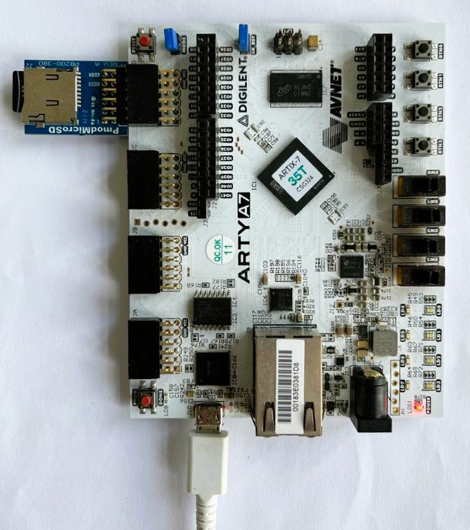
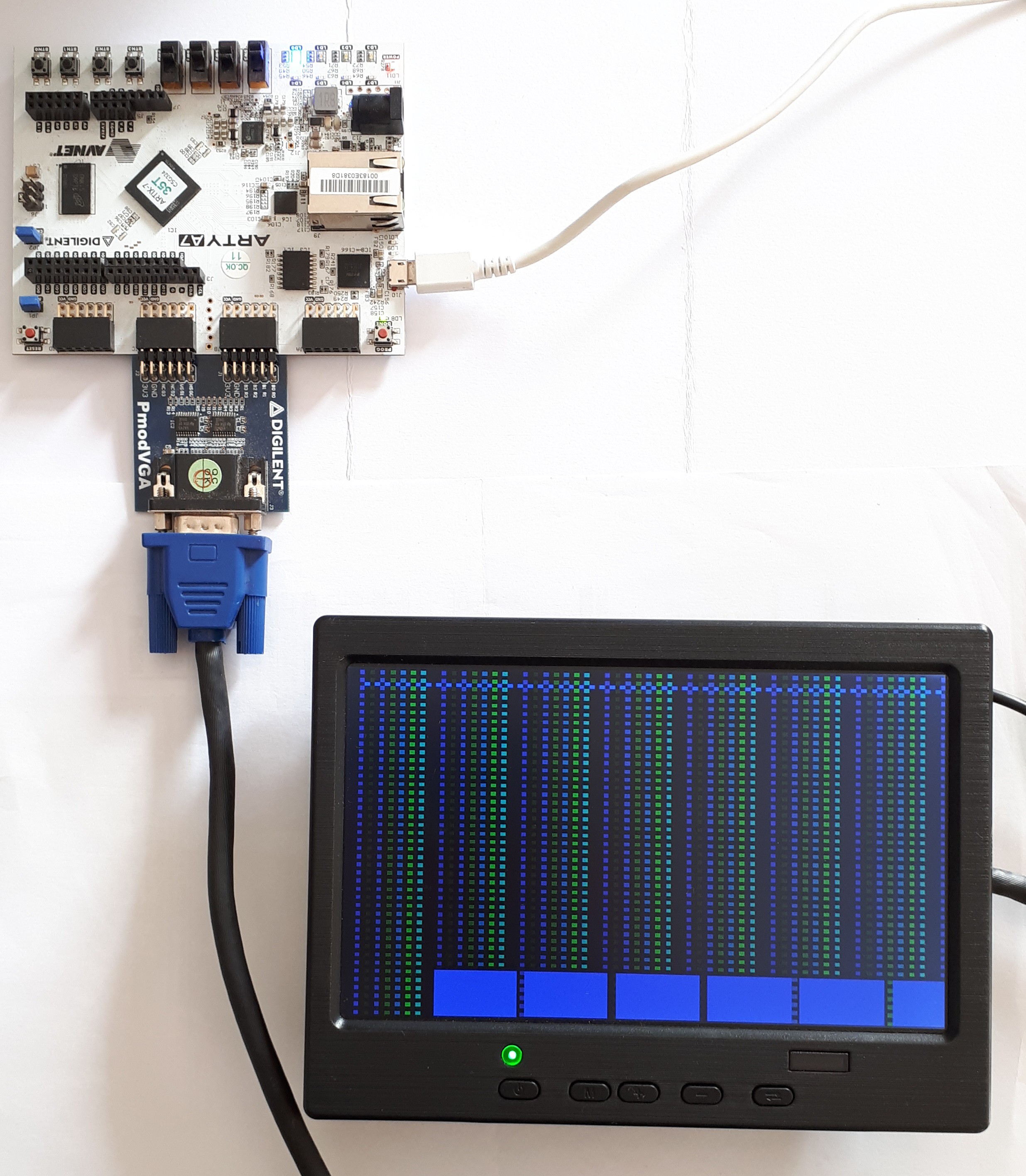
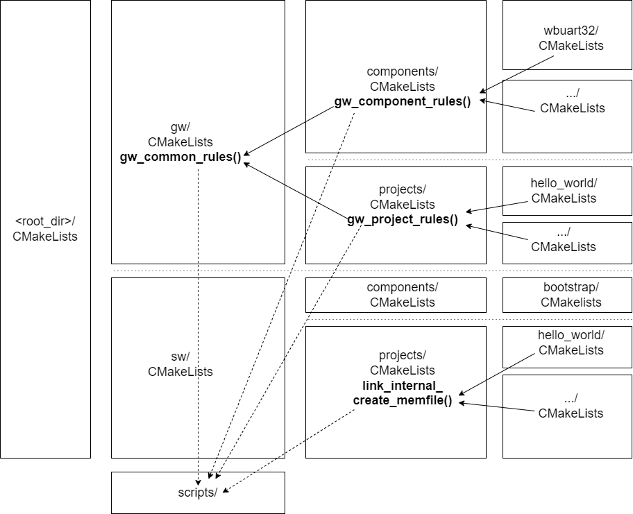
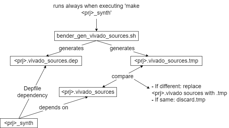
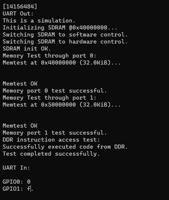
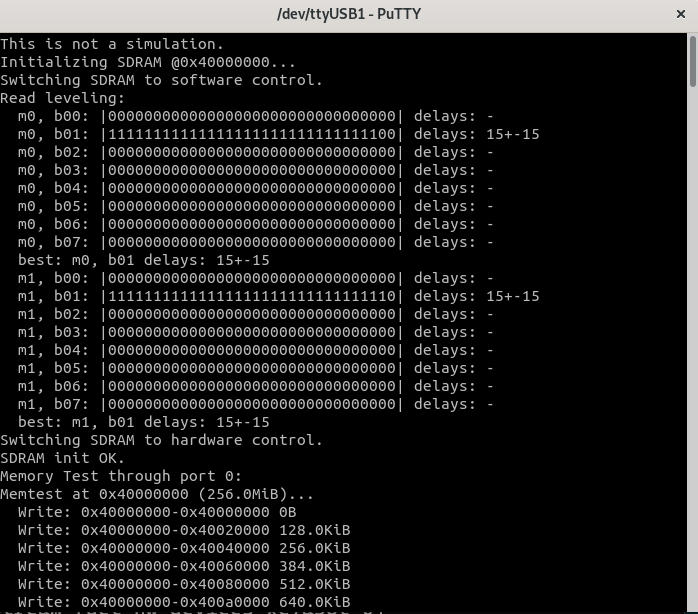
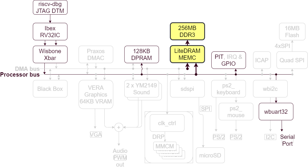
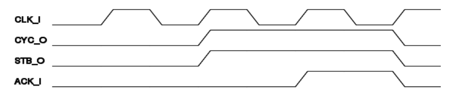
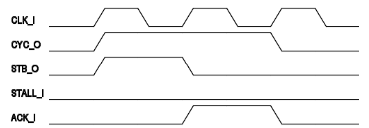
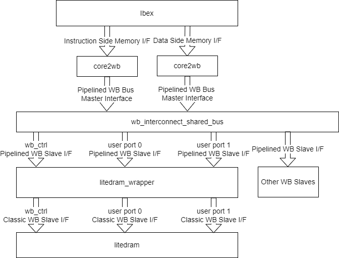
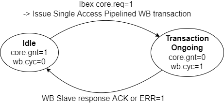
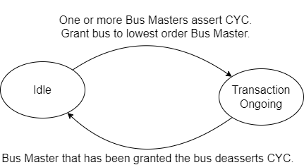
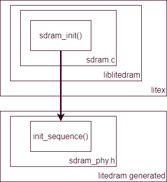
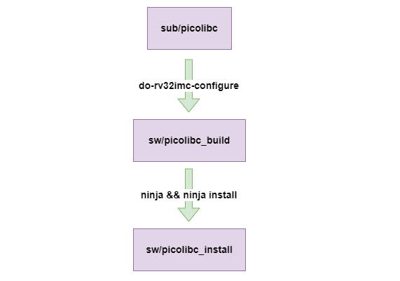
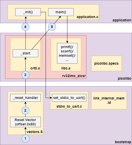
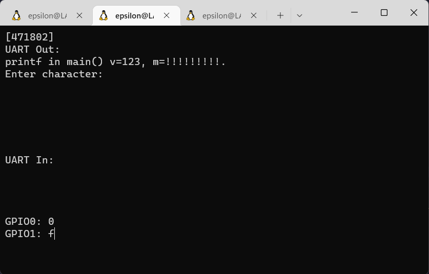
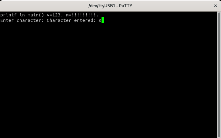
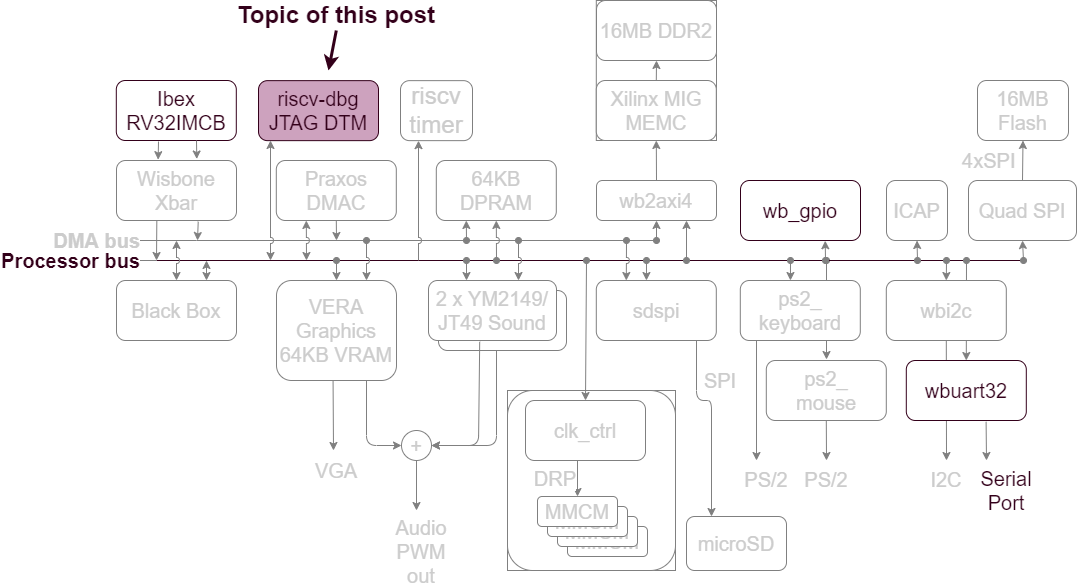
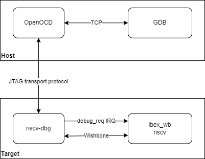
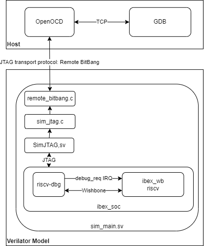
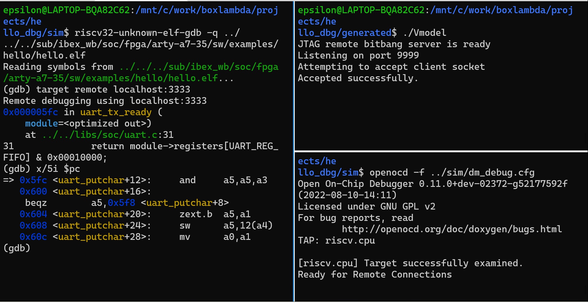 OpenOCD JTAG Debug Session on Verilator
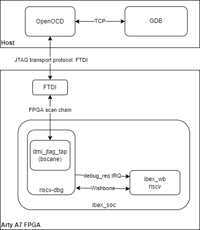
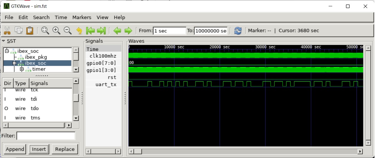 Gtkwave View of Waveform Trace Generated by *Hello World Verilator Test Bench*