Ruediger F. Loeckenhoff
-
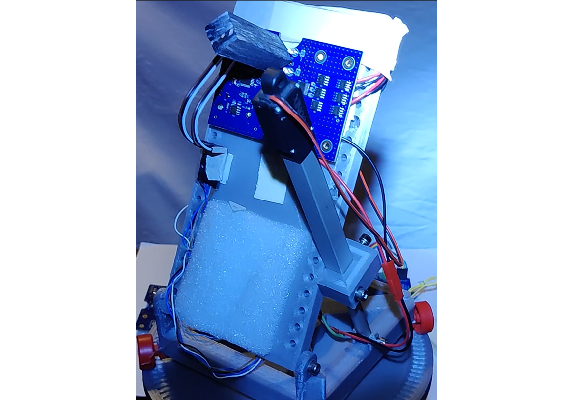
Successful test of the integrated board on a table top tracker.
12/28/2022 at 20:40 • 0 commentsThe integrated board works as expected on my desktop tracker. I had to do only minor adjustments to the code (pinmapping, etc.). The main issue is the z-axis zero offset of the MXC4005XC. This amazing chip monitors the convection within a tiny volume to calculate the acceleration. This works very well for the x and y components but the z component can be off by +/- 0.5g. Therefore, we need to set one more parameter in EEPROM, the z-axis acceleration offset for which I used the ascii sign "_" in my table. (Each of the 64 parameters in EEPROM is indexed with an ASCII sign).
![]()
-
Success: The new boards work!
12/10/2022 at 09:30 • 0 commentsThe first boards have arrived and they work! I also assembled a test board that contacts the pins of the tracker board and connects them to an Arduino Uno.
Uploading the bootloader worked well and the tracker program is also working. I need to swap some axises to make it track. Those are minor adjustments.
Furthermore I need to make a test program that tests all devices and creates a test report. This will be the last step to mass production capability.
Or to make it clear
****** S U C C E S S - We did it! ******
-
Desktop tracker with new sensors
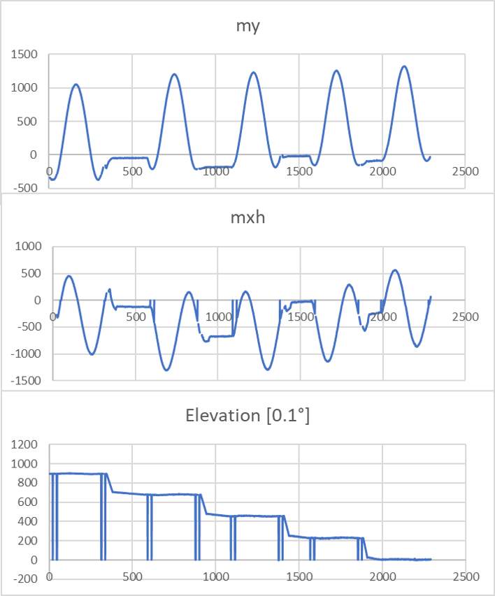
11/20/2022 at 20:47 • 1 commentPCBWay promised to try and send me the 25 new boards before Christmas. They would have been faster but my package with parts got stuck in the mail (Corona-Lockdowns...). To make use of the time, I tested a board with the new sensors on my desktop tracker. The MMC5603 magnetometer is better than the MPU9250 but the MXC4005XC accelerometer is noisier. I am now applying 20x oversampling to both devices in parallel with good results. The calibration routine ran through smoothly and the tracker behaves as expected. Below you can see the readings of the magnetic my component and the mx_horizontal component which is composed of mx and mz.
As you may see from the readings, the tracker is doing full azimuth sweeps starting at 90° elevation and going down to 0° elevation in 4 steps.
![]()
This is the final proof that we chose suitable components.
Once the new boards arrive I will have to figure out the programmer board which uploads the code and which should also do a quick test of all functions to make sure that the tracker board is working properly.
-
Pogo board files are public
10/30/2022 at 19:30 • 0 commentsThe Pogo test board files (Eagle) have been published under MIT license as Pogo_board.zip.
-
Further strategy
10/30/2022 at 04:59 • 0 commentsI just ordered 15 pogo pin boards and I ordered all necessary components a few days before. All parts arrived already. So I will be ready to go to build up the first pogo boards and test the tracker boards, once the delivery from PCBWay arrives. I liked the option that allowed me to combine shipping with the order for the assembled boards that I placed before. That spares me a lot of shipping cost.
Ermanno will come to Germany for the Electronica fair and I will meet him for the very first time. Isn't that funny, considering that we have spent so much time together in Skype figuring out the right parts and arrangements?
In any case, on our way to Munich, we will have a lot of time to discuss the further strategy of how to push this board into the Arduino and RasPi community as a standard part to consider. Offering it for a share of the cost and possibly also at PCBWay is a start. But these will only be a few parts to be sold and we will have to test them all. This is not our final goal yet. We need to find a company that decides to make them in quantity and promote them in their shop (maybe with a label: winner of the 2020 hackaday price). Once that happens, the board may be picked up by rebuilders and we are where I wanted to be from the start:
A unviversal solar tracker controller will be widely available
-
Test board ready for ordering
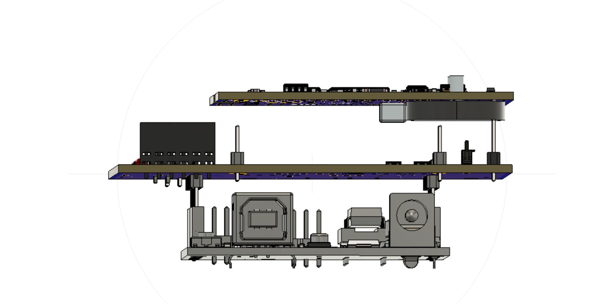
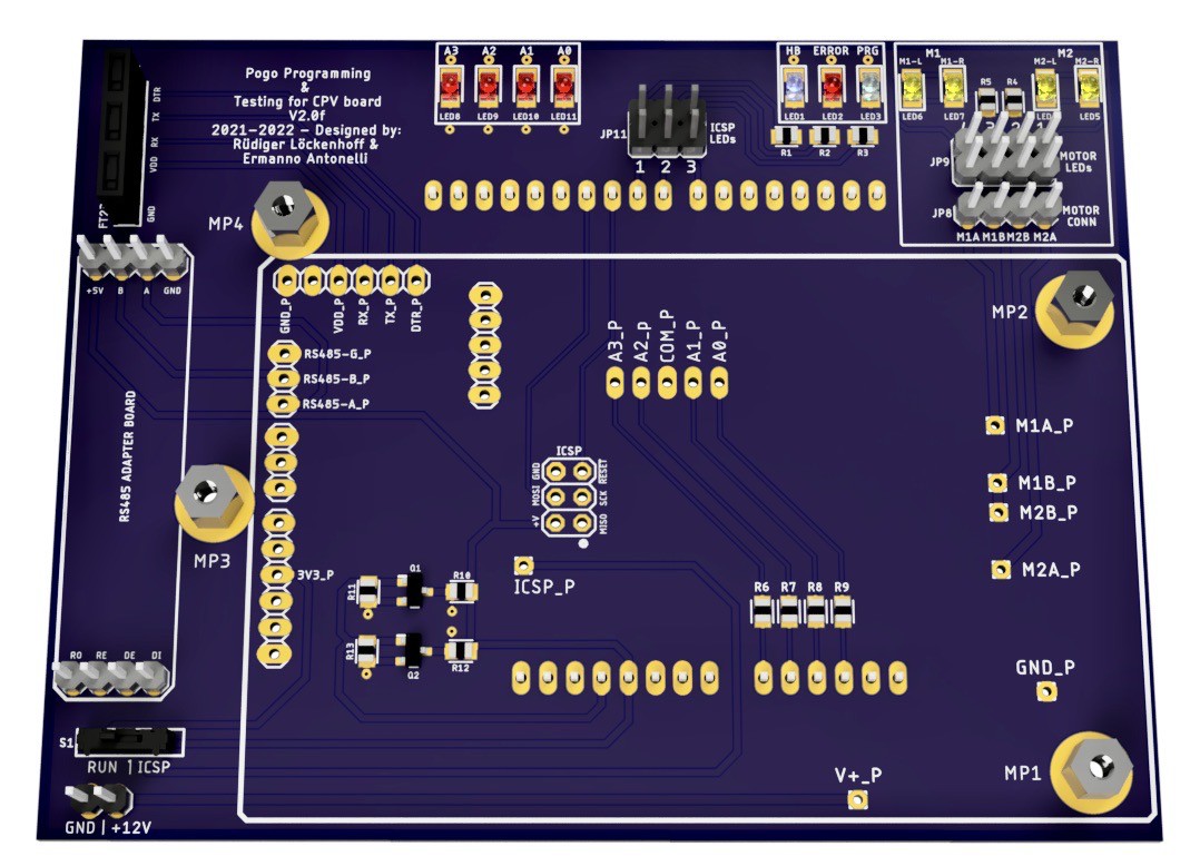
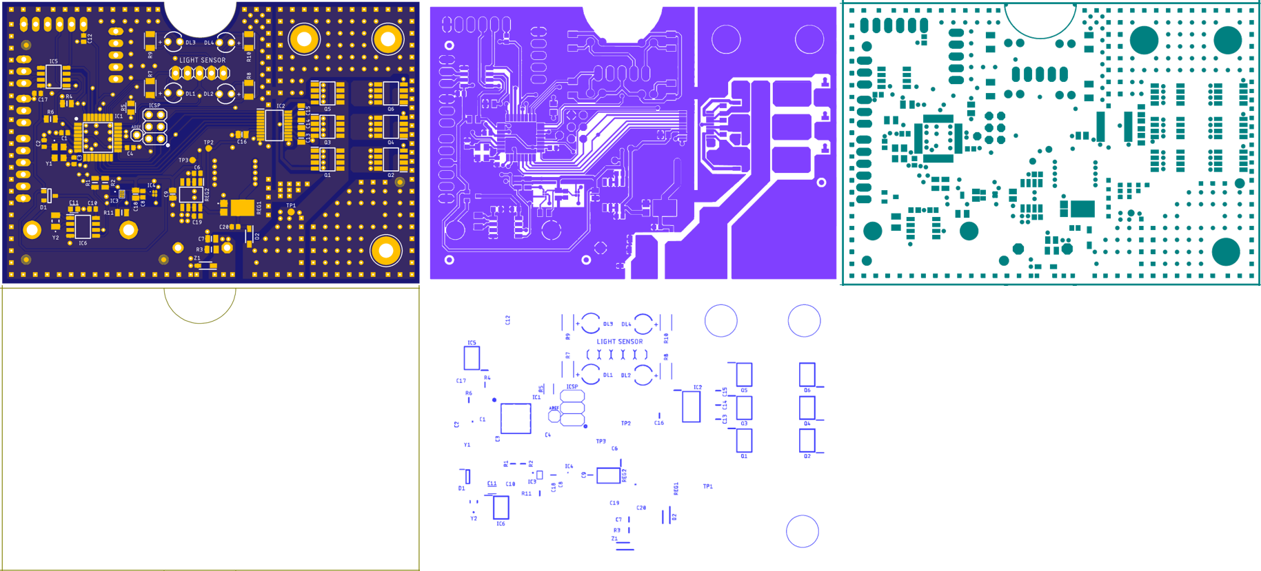
10/27/2022 at 13:16 • 0 commentsAfter several discussions with Ermanno he finished the design of the test board with pogo pins that will serve for ICSP programming and testing of all components of the tracker board. In the figure below you can see the test board in the middle. It is mounted as a shield on top of an Arduino Uno and the tracker board is pushed backside down onto pogo pins (pogo pins not shown). The Arduino UNO can either serve as an ISCP programmer or as a test platform.
![]()
![]()
And here is a rendering of the populated tracker board.
![]()
The positions that will get pogo pins are marked with a _P in the silk screen. The RS485 adapter will be on the left with the voltage selection switch (Run / ICSP) underneath. The four LEDs on the upper left side should only come on when there is something wrong with the sun sensor. They are a protection for the tracker board when we are applying 5V through a resistor to test the analog input.
Then there are the ICSP status LEDs on the upper right. Finally the motor output with status LEDs is in the upper right corner. The tracker board is pused onto 3mm screws and fixed with nuts to make it push down against the pogo pins.
A full test will probably include the following steps:
1) Upload bootloader and test program via ICSP.
2) Change voltage to 3.3V and power up all 3.3V hardware by swapping a switch. Connect 12V supply.
3) Run a test programm to check compass chips, RTC, photodiode tracking sensor, motor controll (all directions), motor current measurement, RS485 communication between tracker board and UNO.
4) Calibrate z axis of the accelerometer by swapping the assembly upside down. Store the results in the EEPROM.
5) Use FTDI adapter to upload the tracker program and check that the bootloader is working.
With these steps, the tracker is ready for shipping. Since we must reprogram the UNO between 1) and 2), we will probably do 1) for a couple of boards and go on with 3)-5). We will need some of those QC stickers too, to make it look professional.
Ermanno will upload the board to PCBWay and we will see whether it processes correctly. I will order a few boards then to build up at least two test rigs.
As soon as PCBWay confirms that the CAM files processed correctly, we will upload them here as open source (MIT license).
-
Greetings from Ermanno
10/23/2022 at 13:18 • 0 commentsHi Everyone, Ermanno here.
I'm thrilled to be part of this project with Rüdiger being the scenes. I have contributed to the electronics design and PCB miniaturisation. All things consider, we managed to pack a lot of features in such a small board. Working with Rudi we pushed the concept of doing more with less even further and I think we succeeded. Now working on the test gig for mass production. If you look at the open source files, most of components are either Eagle standard libraries os sourced via SamacSys plugin. refer to the note in the schematics for any component question and feel free to give us a shout.
All the Best,
Ermanno
-
*** Uff - A busy week ***
10/23/2022 at 07:46 • 0 commentsUff, that was a busy week. My regular work, handling the orders at PCBWay, having long Skype discussions with Ermanno about the best test scheme and polishing up the project site for the contest. In particular, I realized that my video was 6:30 min and only 5:00 min were allowed. I's 4:58 now. Forgive me the somewhat strange cuts in some places.
Let me go through the checklist:
i. Build a working prototype of your project.
- Working prototype of STAGE1 (made from breakout boards)
- Working prototype of V1 board that still required external breakout boards for the chip level sensors which were just not hand solderable. Please see the test documentation in the project logs.
- Prototypes of V2.0f board are ordered but obiously we couldn't test them yet.
ii. Create a video, between two (2) minutes and five (5) minutes in length:
- It's 4:58
iii. Project Profile: On the Project Profile:
a. Link to the video
- Done and tested.
b. Post high-resolution photos of the project inside and out
- For STAGE1 refer to 2021_08_14_Full_description.pdf
- For STAGE2 refer to the logs and the renderings in v2_0f_board_for_solar_tracking_and_robotics.pdf
c. Update and add detail to info entered at the previous stage(s)
- Done
d. Show at least ten (10) Project Log updates or at least ten (10) Build Instructions updates
- This is project log No 24 and I asked Ermanno to say hello in Log No 25 and prove that I didn't just invent him to simulate teamwork. We should be fine.
e. Post a components list that is complete with a bill of materials for one unit
- For STAGE1 refer to 2021_08_14_Full_description.pdf
- For STAGE2 look at the Excel file in here Magnetic_CPV_Tracker_v2_0f_Eagle_CAD_CAM_BOM_documentation.zip
f. Post reproducible build instructions
- I put a lot of effort into the build instructions for STAGE1 2021_08_14_Full_description.pdf
- For STAGE2 we don't recommend trying to solder this board yourselves. Have it assembled professionally or apply for one of our prototypes at a cost share of $40.
- I describe our plans of how to mount and encapsulate the board here. v2_0f_board_for_solar_tracking_and_robotics.pdf
g. Post complete schematics and documented input and output requirements and specifications for your module/design h. Publish all design files Including Gerber files (req – RS274 / RS274X), STL files (opt), netlist (opt), nc drill files (req – human readable), ODB++ (opt), STEP (opt), PCB files (opt), or any other design files
- STAGE1 uses a clever assembly of breakout boards with a minimum amount of wiring and without any extra PCBs 2021_08_14_Full_description.pdf
- For STAGE2 all the required files are in here Magnetic_CPV_Tracker_v2_0f_Eagle_CAD_CAM_BOM_documentation.zip
I's all there and I feel good about it. I guess we reached a fair level of openness. All publications are under MIT license and we promise to add the test board design and operating instructions for the V2.0f board once everything is working. I may also invest time into the adaptation of this board to robotics (I2C slave) but I cannot promise that yet. It would be great if a 3rd team member (or more) could take over that job. And then it all depends on finding a community and a company that will use the board for solar tracking on large scale.
-
Working files released
10/23/2022 at 07:15 • 0 commentsThis was the first time for me that I ordered an electronics assembly so I think I may share my experience.
First of all, most of the credits should go to Ermanno Antonelli who spent hours and hours figuring out the component data sheets, designing the board and populating the components list. He generated a CAM output in Eagle and a BOM list in Excel.
At PCBWay you have to make two orders - one for the boards and one for the assembly. I already had some ATMEGA328pb-au and also the RS485 chip which is not so available right now. So we chose the option where most parts are sourced by PCBWay and some are provided by us. Unfortunately, the TVS diode is not available to PCBWay and I didn't order it yet. So I will have to solder it myself. But that's easy. It is a big part on the back side.
Ermanno then uploaded the CAM files and the BOM as an Excel file. PCBWay wanted a certain format, so better use their template from the start, if you plan to order there. The layout was processed by PCBWay and cleared. I received an updated version of the BOM where PCBWay had marked components that had to be replaced and suggested alternat versions. In some cases it was just a difference in the format of the serial number. I had to answer in another column of the table and yet received an updated version from PCBWay for a final approval. The BOM issue was handled in a very effective and professional way.
With this settled, the final price for the assembly was calculated and I had to pay - with a generous sponsoring from PCBWay who like this project. We will offer boards for a share of the total costs including shipping and parts provided by us. This will amount to a total cost share of $40.
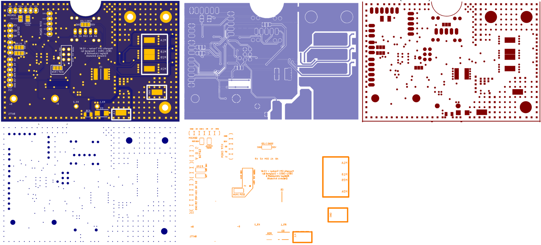
Finally I received the working file plots from PCBWay. I wonder whether PCBWay will allow me to make them public too. I will ask.
In any case I copied them all to powerpoint and compared them to the renderings of the board that Ermanno had sent me. They all matched. You will find the printouts below.
Ordering PCB Assemblies is actually not so hard - if you have Ermanno to prepare the files for you.
![]()
![]()
-
Don't forget about testing!
10/21/2022 at 15:28 • 0 commentsIf we want to get close to a professional product we need a testing scheme. This would not be necessary for the 25 boards we ordered now, but for a mass production by a major assembly company. This is our goal, after all and there is no reason, not to do it right from the start.
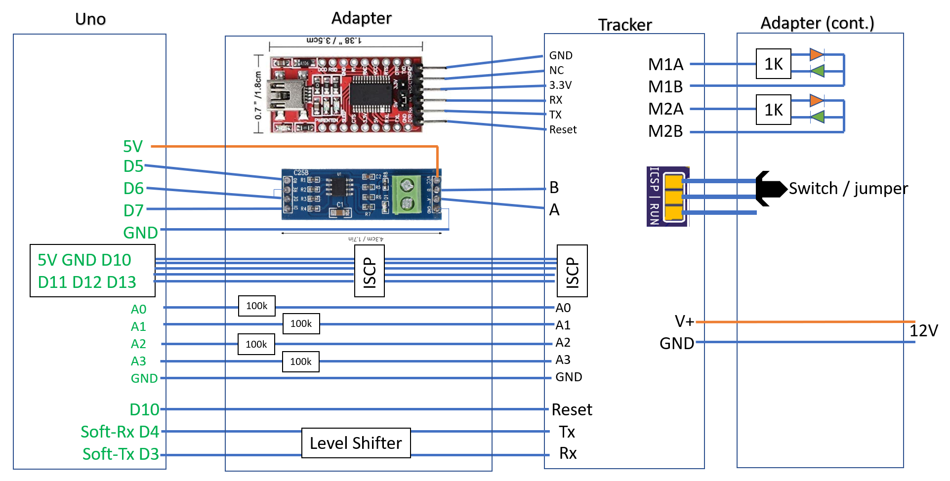
Even for just uploading the bootloader and code, we need a board with pogo pins. An Arduino Uno will serve as an “Arduino as ISP”. Since we will have that board already, it should also do the testing. My idea is, that the Arduino Uno should handle the serial interface of the tracker board and go through the first calibration steps. If all serial responses of the tracker are correct, it is obviously working.
The functional test should include the sun sensor and the motor control. In the third calibration step, the tracker follows the sun with the tracking sensor. We can simulate a tracking signal by sending a small current to the photocells. As a result, the motors should start running and the current sensing should sense the motor currents in all directions.
All serial communication between the tracker and the UNO (soft serial) will be mirrored through the native serial port of the UNO to the computer. Furthermore there is a max485 adapter on the board to test the RS485 communication.
Setting up the full test program will take time. Therefore, we also include an FTDI USB Serial Adapter to address the tracker board directly from the computer.
This arrangement should make uploading and testing easy. You can see my scheme below and yesterday evening I had a long session with Ermanno to discuss the schematic and board layout. He is great.
![]()
Open Concentrating PV Solar Tracker Controller
Achieve better than 0.1° sun tracking accuracy with a compass a tilt sensor and a shading beam sun sensor.