NuclearPhoenix
-
Software Changes for FW 4.0.0
12/03/2023 at 11:01 • 0 commentsHello again, just a quick post to keep you updated on the software changes that I did to the new 4.0.0 firmware. Yesterday I already mentioned my work on the software without telling you what has changed. So here we are, these are all significant changes to the firmware:
- Removed command for the buzzer on-time per tick. It's now fixed to 10ms.
- Added command to enable/disable the buzzer. (default is off)
- Added command to set the tick rate of the buzzer. (default is every 20 pulses)
- Added a running median for the device dead time to better compute the current dead time.
- All cps values on the display are now also dead time corrected. This applies to both the energy measuring and geiger modes.
- Implemented the additional button on the PCB to toggle the buzzer on or off.
- All serial commands that took "enable" or "disable" as a parameter now use "on" or "off". So, for example, "set display enable" now becomes "set display on". If you're not sure, the "help" command tells you exactly what you need to know.
-
More Tests and Documentation
12/02/2023 at 19:42 • 0 commentsI already updated most of the documentation on GitHub and did a lot of additional testing. I also did most of the things I wanted to do for the firmware and uploaded the first 4.0.0 FW files. However, there are some "bad" news: the energy resolution didn't change a lot if at all when compared to the last revision. More testing revealed it stays much the same, so that was a fluke. But that doesn't change the fact that all the other changes and improvements still hold.
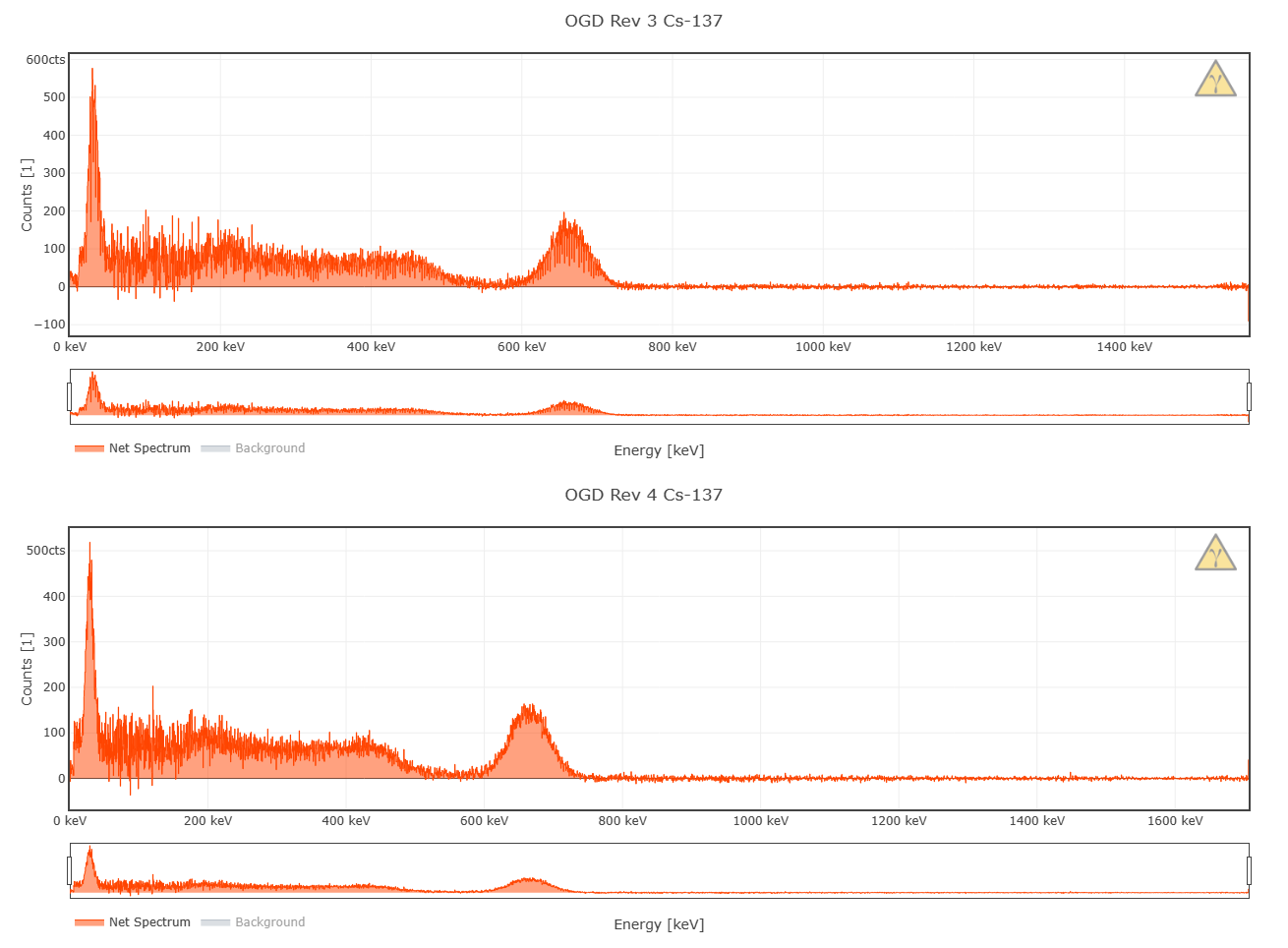
I did some more testing on the energy range and noise levels too and these are my (practical) results:

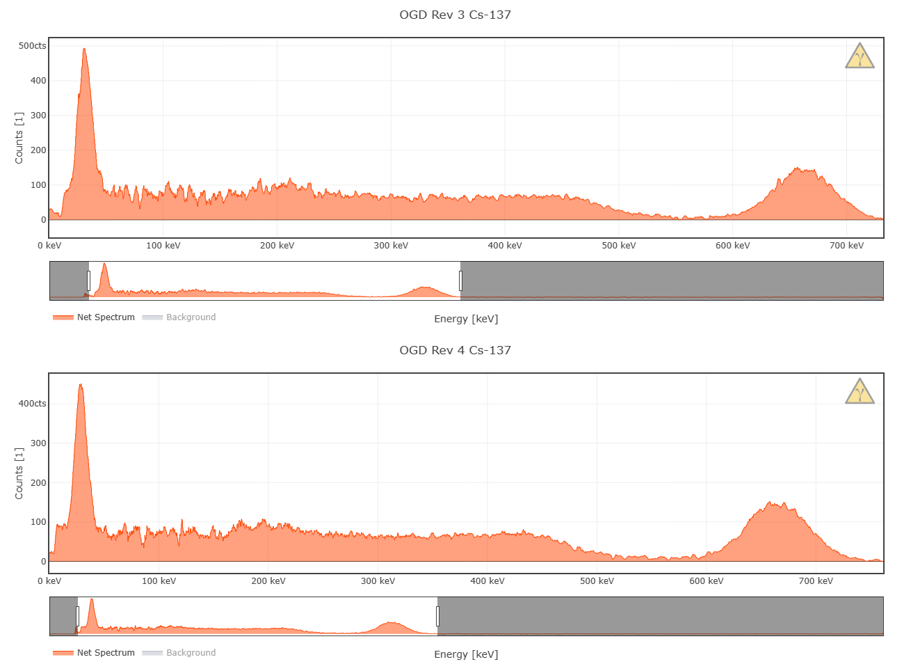
Can you see the difference? I'm sure you can. The new hardware produces a LOT cleaner spectra and if you look closely you can see the background plateau extends farther to the left after the 32 keV peak up to around 10 keV. This will be more visible in the next images. All of these spectra were recorded using the same crystal, same settings and everything. I recorded my mushroom sample, that's why I got these nice Cs-137 peaks.
As you can clearly see, the peaks are a bit cleaner in general and the measurable plateau extends farther to the left after the 32 keV peak all due to the lesser noise floor. I've now used SMA 8 for both of these spectra. You can also see the reduction in noise in the compton spectrum to the left of the photopeak.
I'm also still currently recording some new example spectra for GitHub and after that I'll check if the two modes of the SMPS on the Pico result in any changes and what averaging setting is the best for energy resolution. I'll keep reporting my findings of course.
Still waiting for the updated OSHWA certification, once that's done, the new PCBs will go into production for Tindie and I will update the PCB files one last time to update the cert mark. I think I already mentioned the updated Tindie price in one of the last posts: it will have to go up by 5 bucks to accomodate the 4L board and the extra components, so the price will be 64.99 USD. I think that's more than fair given all the added value :)
The Tiny SiPM breakout board will get a bit cheaper, it'll be around 1.00 or 1.49 USD. I'm also thinking about adding the temperature corrected standard MicroFC breakout board to the store. Let me know if you're interested in that!
Cheers!
-
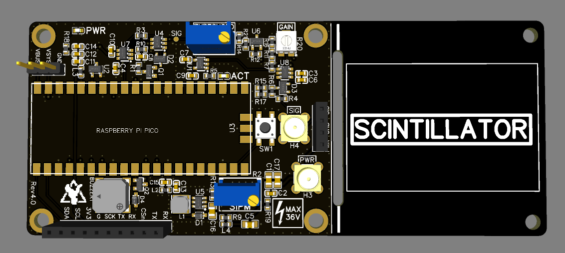
Revision 4.0 Status Report
11/28/2023 at 22:55 • 0 commentsThe latest hardware revision of the board is now almost complete. I've finished work on the hardware, did some testing and adapted the Arduino sketch to work on the new hardware just now. I'm very shortly going to talk about all the changes with the Rev 4 hardware.
Most of the actual circuitry has been taken straight from the last revision with only minimal changes. So like I said in one of the last logs here on Hackaday, this is mostly a quality of life update and largely concerning the change of the PCB layout.
Here is a list of all significant changes to the electronics:
- Added a small buzzer
- Added an additional button
- Added two MCX connectors for a much improved and reliable connection to your SiPM/scintillators
- Added an optional gain trim pot for the pre-amp
- The PCB now has 4 layers instead of 2, with much improved board layout and layer stackup resulting in a lot less noise according to my tests
- Changed the two 4-pin and single 2-pin headers for a single 10-pin header for the broken-out GPIO pins
- Added an additional cap to the SiPM PSU output for better stability
- Increased decoupling cap size in general all over the board
- Swapped out some critical resistors for ones with less tolerance and a much lower temperature dependency to increase the detector response over vastly different temperatures. In the past especially the threshold voltage could be easily disturbed by a change in temperature. This is now a lot better according to my testing as well, I didn't have much of a threshold drift up to almost 60°C.
- Decreased the threshold voltage range maximum to a more reasonable value. This also makes setting the right voltage a lot easier and helps with drift.
- Added a board cutout to help with separating the two PCB sections if you decide to cut the additional space off
- Some part consolidation (BOM)
Admittedly, this is all a bit technical, but I guess you're here for the tinkering and the behind-the-scenes stuff anyways ;D
In short, what does this mean for you, the user? Well, first of all, you finally got a buzzer and an additional button, how nice is that? You also got a more reliable option to connect the SiPM if you so desire. The device should also be a bit more stable now in general. And on top of all of that, I got a noticeable improvement in energy resolution (up to 1%, but I have to do some more testing on that) and I was even able to get a usable spectrum down to about 10 keV due to the less noise!
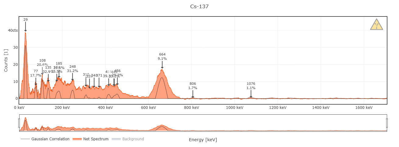
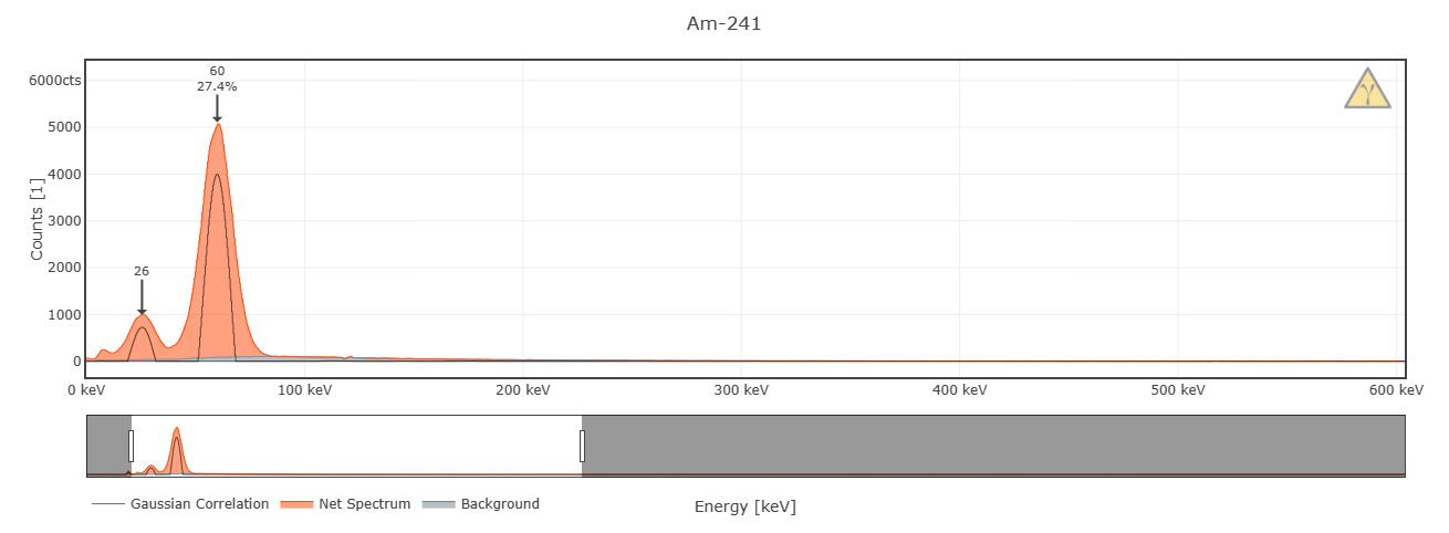
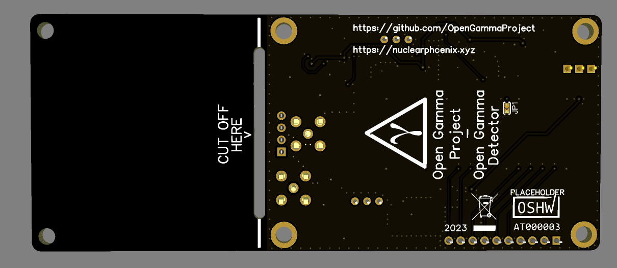
Here are two test spectra that I did that back what I just told you (only 30 minutes, so expect results to be a bit better with longer recordings):
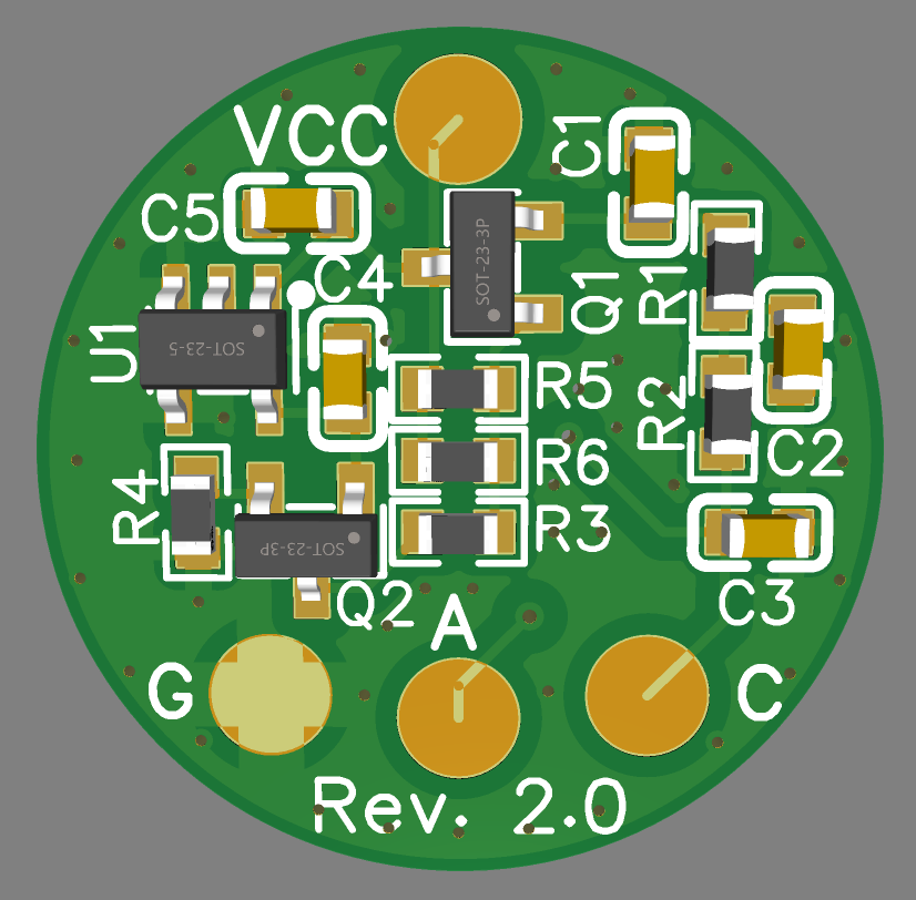
About 9% energy resolution with a 9% scintillator and a single SiPM. Easily able to fully resolve the lower ~26keV peak of Am-241. Range goes down to about 10keV. Here are some renderings on how the final PCB looks like (with an OSHWA mark placeholder). I already have an assembled one here, but that's nothing worthy of showing off due to all the soldering and changes I did to it ;)
I am going to do some more testing for the Arduino sketch that runs on the Pico and I still have to implement the button and some other buzzer-related things. It already works totally fine and stable just like the old software, only some functions are missing and I want to do some more optimizations on top of that.There will also be another batch of assembled PCBs on Tindie in a couple of weeks, this time the pin female headers on the board will also come pre-assembled in contrast to the last batch where they were left out. Price will probably need to go up like $5 per piece to compensate for the added parts and the 4L board, but I think that's more than fair given the number of improvements ;)
So stay tuned for more updates on the Tindie stock as well!
In addition to all of that, the PCB will also get a final, tiny update when I get the OSHWA certification again (just adding the mark to the silkscreen). There is still a lot to do for me, I'm going to slowly update everything here on Hackaday and on GitHub over the next few weeks, I will keep you updated.
Have a nice week!
-
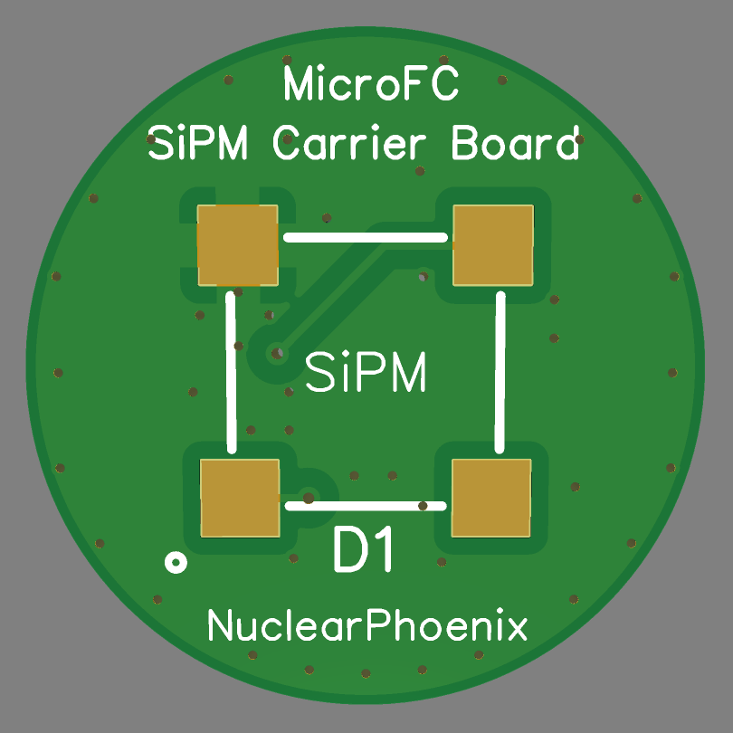
Updated 2x2 SiPM Array
11/24/2023 at 17:30 • 0 commentsJust did a quick rework of the 2x2 MicroFC SiPM array PCB, added the temperature compensation from the single PCB and cleaned up the layout in general. It's now 2x2cm in size and still keeps the easy solderability for the four SiPMs (results in a fill factor of ~40%), while also adding the ~21mV/K slope for the power supply.
Front side with only the four SiPMs Back side with all the other components If you want to use it, just connect your power to the "VCC" pad, ground to "GND" and then the SiPM anodes to the spectrometer. You can check the set voltage at the "C" pad on the PCB. If you don't want to use the extra circuitry, you can just solder your power straight to the "C" pad and not bother with the other circuitry. However, you'll still have to solder the low-pass filters for each SiPM, otherwise they won't work.
You can find all the files here: https://github.com/OpenGammaProject/MicroFC-SiPM-Array-Board
Let me know what you think!
-
New hardware revision?
09/20/2023 at 15:55 • 0 commentsTo break the silence, here is a short update on what's going on behind the scenes right now.
At the moment we're looking into a possible hardware revision 4. This one mostly focusses on the PCB and component layout to improve shielding and optimize the total device size. There is a lot that can still be done in this regard and we'll test it thoroughly before release. In the best case this will keep on improving the energy resolution of the device and the new revision will also include some smaller quality of life improvements. Follow the project so you don't miss out on any updates.
On another note, the OGD is sold out on Tindie, so thank you all for your interest in this project and the support. You can still get some of the Tiny MicroFC breakout boards if you want, the sale is still on until the end of september.
Cheers!
-
End Of Summer Sale
08/31/2023 at 09:51 • 0 commentsFrom September 1st to 30th there will be a site-wide sale (-10%) on my Tindie Store, including the Mini SiD, the Tiny MicroFC SiPM breakout board and the Open Gamma Detector. No limit on the number of uses or products!
-
Tiny SiPM Boards on Tindie
08/22/2023 at 10:37 • 0 commentsFinally, the Tiny MicroFC SiPM breakout/carrier boards are now available on Tindie! I have added some volume discounts for the PCBs and purchase options together with the Mini SiD and Open Gamma Detector.
Link to the store page: https://www.tindie.com/products/31304/
Thanks to all the feedback and demand from you guys for the SiPM carrier boards. It's been long overdue to add these to Tindie so that you can get the PCBs together with the detector electronics.
-
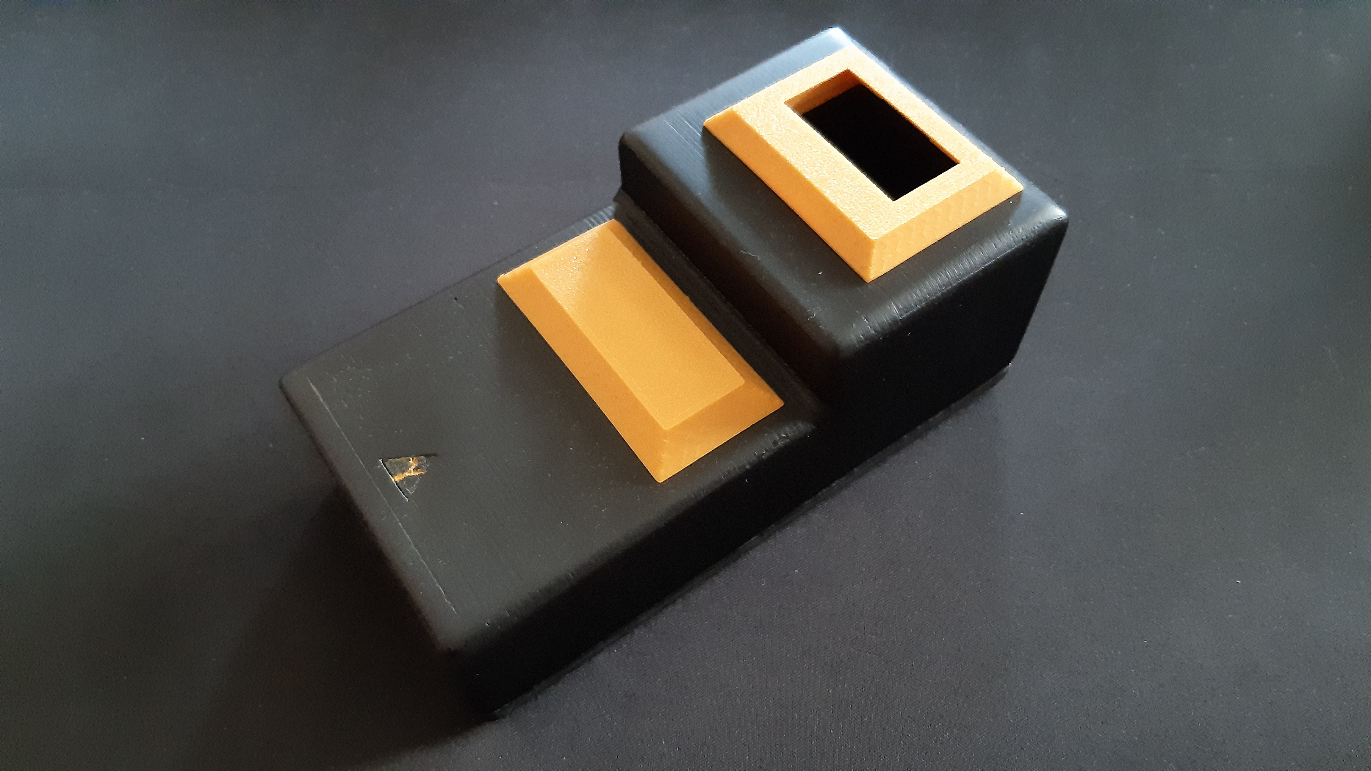
Improved Case
08/19/2023 at 12:33 • 0 commentsHere is a new and updated case design for the Open Gamma Detector Rev.2 and 3!
It's a lost more compact and features friction fit slots for panel and display mounts. There are STL files for a default display mount for an SH1106 1.3 inch OLED screen and one for a solid panel cover. You can design some custom parts to fit your needs, especially with the front panel, and then just slot it right in.
The detector main board is screwed in the bottom plate that is then attached to the top. All the screws are designed to be screwed into inserts and the large front section of the case can fit up to a 5x5x5 cm scintillator.
Just uploaded all the STL files to GitHub!
-
Temperature-compensated SiPM carrier board
07/26/2023 at 18:19 • 0 commentsHi there!
Here is a new and updated revision of the MicroFC SiPM carrier board: It now has some extra circuitry for temperature gain compensation! The overall size of the PCB and the solder pads have not changed at all and the bias filtering is also still on there. In addition to that, you can also use it without any of the additional electronics on it too. Don't need temperature compensation or any of the filtering? Just leave out all the components on the back side and solder directly to the anode and cathode pads for the SiPM.
If you do want to use the compensation circuit, a new BOM, Gerber file and schematic have been uploaded to GitHub. Kitspace should update too in the next couple of days (hopefully). Here is a link to the repo: https://github.com/OpenGammaProject/MicroFC-SiPM-Carrier-Board
It works completely passively without any sort of user intervention. It's based on an NTC thermistor that sits on the back side of the PCB, which is a big plus for temperature accuracy since it's on the same board as the SiPM. It's also low-power enough so that there is no unnecessary self-heating of the PCB. Just be sure to increase the SiPM PSU voltage a little bit as the compensation circuit initially drops a couple of 100mV to increase the temperature range without any need for readjustment. And ideally, you'd want to set the correct voltage at around normal ambient temperature for the correct tracking range (e.g. ~29.5V @ 25C).
Most of the research and testing has been done by Sebastian D'Hyon, so big thanks to him.
Finally, here are some screenshots on what the new board looks like:
Cheers!
-
FW 3.5.1: Tiny update
07/23/2023 at 17:15 • 0 commentsHi there! Just wanted to let you know about the latest update.
This new version mostly just reduces code size and efficiency in the Arduino sketch. There are no changes on the usability part or the handling of the device in general. I dropped the akkoyun/Statistical library in favor for the more specific RobTillaart/RunningMedian lib. It's just a lot better suited for the job and will be even more handy in the future.
Cheers!
All-In-One Gamma-Ray Spectrometer
More sensitive to gamma radiation than a Geiger counter with the added bonus of telling exactly what's inside your samples!