-
Control Station finished
02/02/2023 at 00:43 • 0 commentsThe title basicly saies everything. I managed to stuff every part of the Control Station into one manageable suit case.
![]()
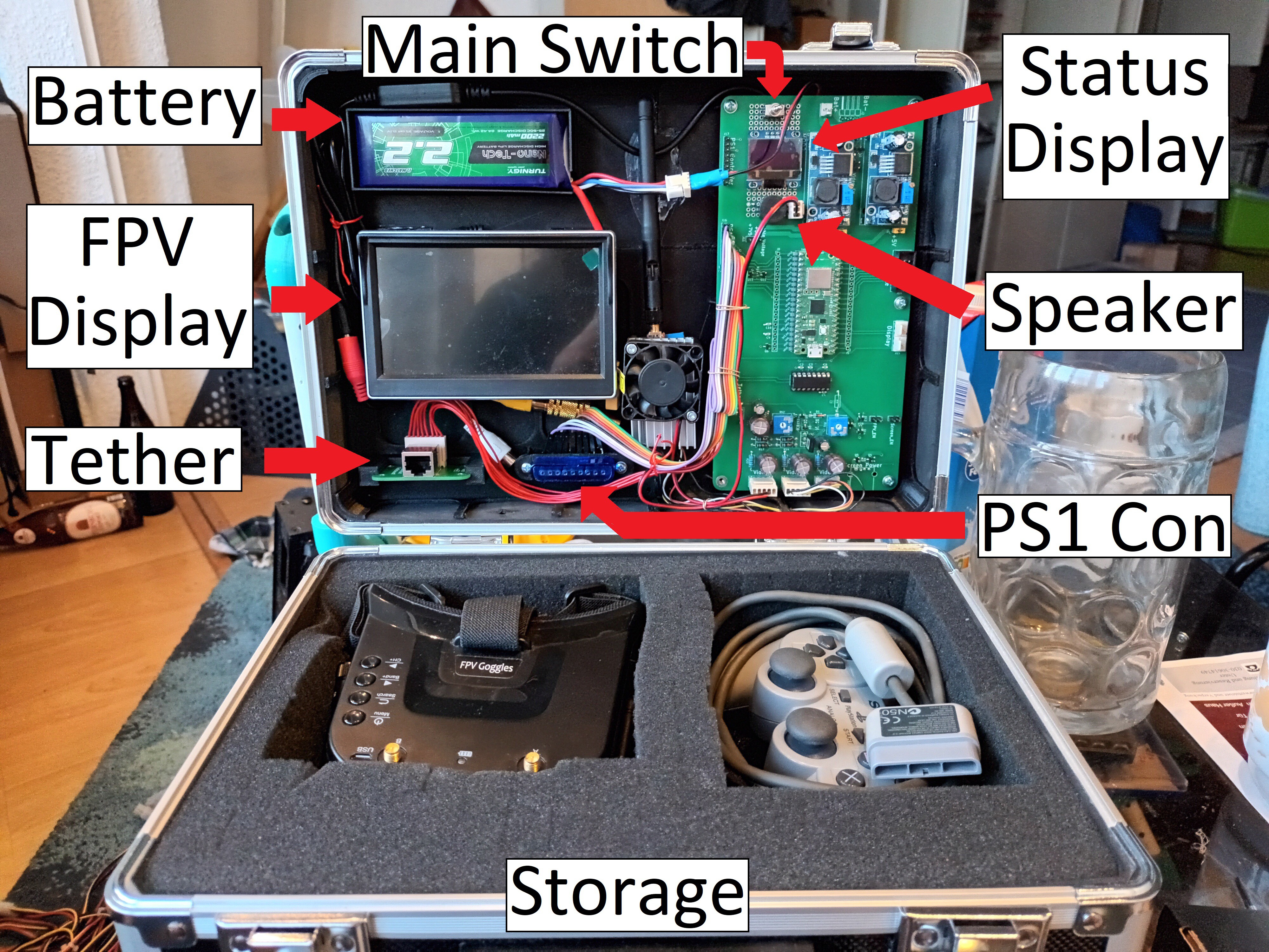
Fig. 1: The finished control station. Just enough exposed wire.
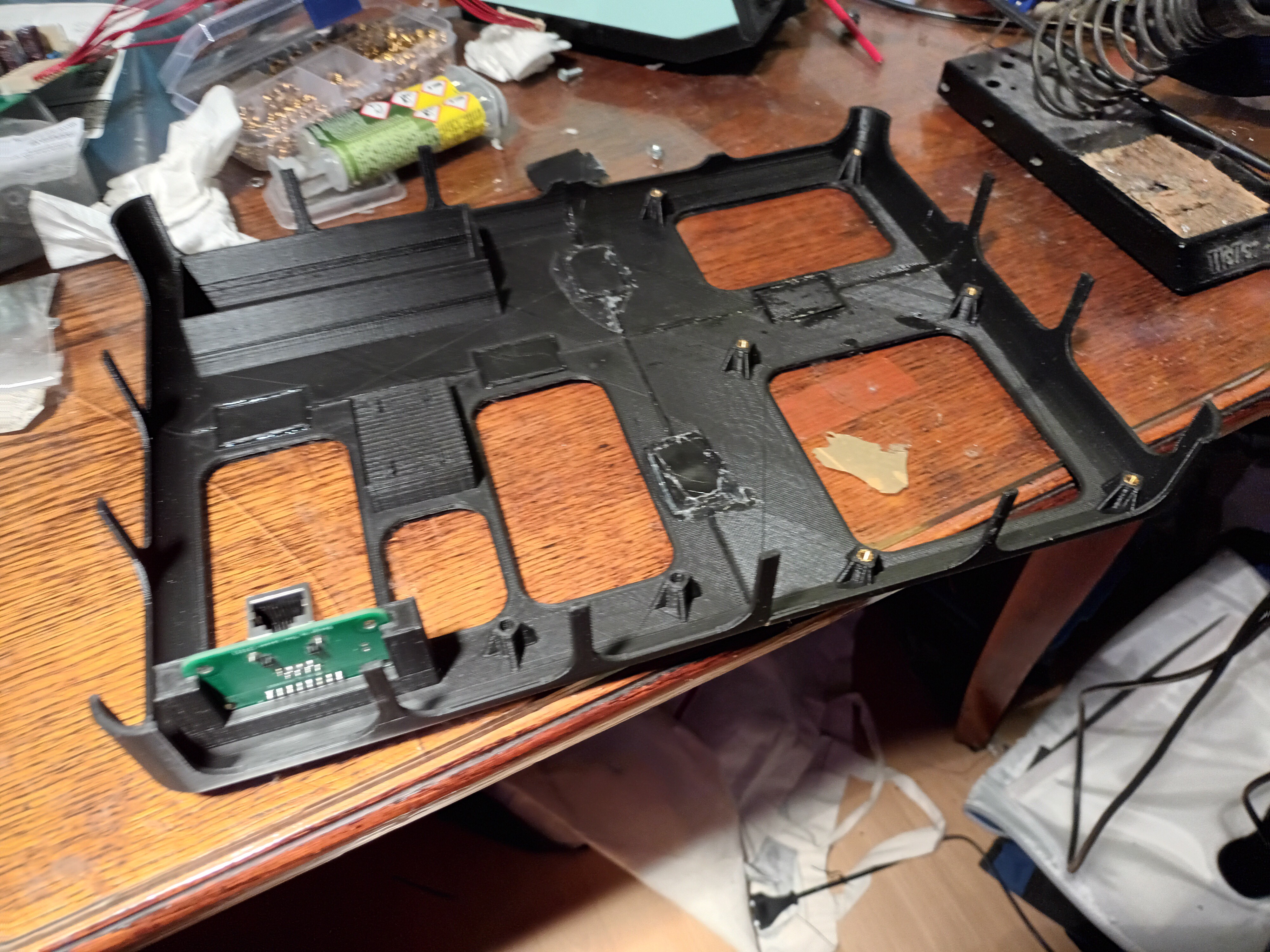
There is not much new information here. You can see an overview in Fig. 1. The only new thing is the heatsink and fan on top of the video transmitter for the FPV googles. Otherwise the thing gets too freaking hot, now its just a good hand warmer during winter (if i ever add an ice pick to the ROV).All parts are mounted on a 3D printed plate (Fig. 2.). The stand offs and mounting points are all integrated into it. The plate itself just preasure fits into the lid of the suit case. Therefore no screws or bolts are visable from the outside and the "professional look" is maintained.
![]()
Fig. 2: The mounting plate for all components in the case. The holes in the middle are there to save some material. As you can see the thing is glued together from four separate parts. PS1 Controller and the FPV goggles can be stored in nice couchy compartments in the bottom of the case.
Unfortunatly with all the stuff in the lid of the case, it is slightly way too top heavy. But i will just stuff some metal scrap in the bottom. -
Documentation
12/20/2022 at 00:46 • 0 commentsThis is an update which explains the schematic of the Control Station. I also finaly uploaded all schematic files for the project and the software in its curent state.
![]()
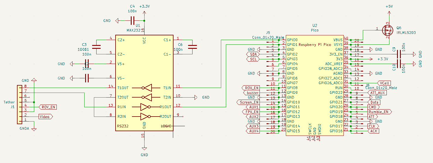
Fig. 1: The RPi Pico and the UART Interface to the ROV In Fig. 1. you can see the RPi Pico of the Control Station and its pin connection. The Pico is supplyed with +5V which is generated on the pcb by the circuit in Fig. 2.
The MAX232 translates the UART to RS232 to make the communication more robust. Its connected exacly like in the application example from the datasheet, so no suprises here. Just one thing: the MAX232 is supplyed with 3V3 from the RPi Pico. This is important because not all versions of the MAX232 work on 3V3, some need 5V.
![]()
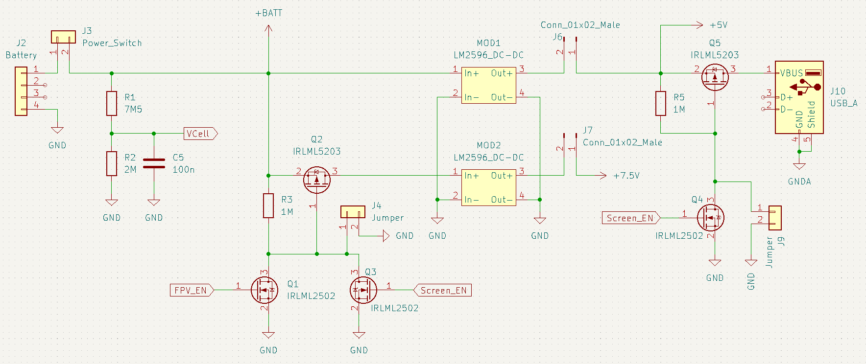
Fig. 2: Power supply of the Control Station A 3 cell LiPo battery is connected via J4. An On-Off-switch is connected via J3, The voltage divide R1, R2 divides the battery down by a factor of 3,75 so that the RPi Pico can measure its voltage via its ADC.
A LM2596 SMPS modul (MOD1) generates +5V from the battery voltage to supply the RPi Pico. Additonaly the +5V also provide power to the CCTV screen via (power only) USB.
The power of the CCTV screen can be turned off via Q5. Q4 is used as a level shifter so the Pico can switch the 5V power supply. The jumper J9 can be set to override the Pico and just turn the screen on for debuging purposes.
A second SMPS modul (MOD2) generates +7V5. This is the analog supply voltage for the video spliter and the FPV video transmitter TS5828. It is also used for the rumbling function of the PS1 controller. This might lead to artifacts in the videosignal down the line but ... fuck it.
The analog supply can be turned off via Q2 in the same way as the +5V supply.
![]()
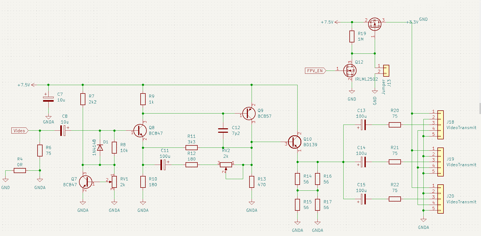
Because i want to be able to use the FPV and the CCTV screen at the same time i need a buffer to drive two video sinks at the same time. The schematic is stolen from: https://www.electronics-lab.com/project/3-channel-analog-video-splitter-with-video-amplifier/
TLDR: The amplifier has an input impedance of 75Ohm. It amplifies the input voltage by a factor of two. It has three outputs each with a an output impedance of 75Ohm each. The inputs of the CCTV screen and the FPV transmitter are 75Ohm as well.
So the amplifier amplifies by a factor of two and the voltage divider of output and input impedance divides it down to a half. So it is effectivly a buffer with three outputs.
Oh, the OLED display and the piezospeaker are directly hocked to the Pico.
-
Failed Prints and New Electronics
11/26/2022 at 01:56 • 0 commentsFor the last weeks i tried and tried to make this damn thing water tight. TLDR: All parts i 3D printed fail during testing or the print fails due to warping. I had enought and gave up, at least for the moment.
![]()
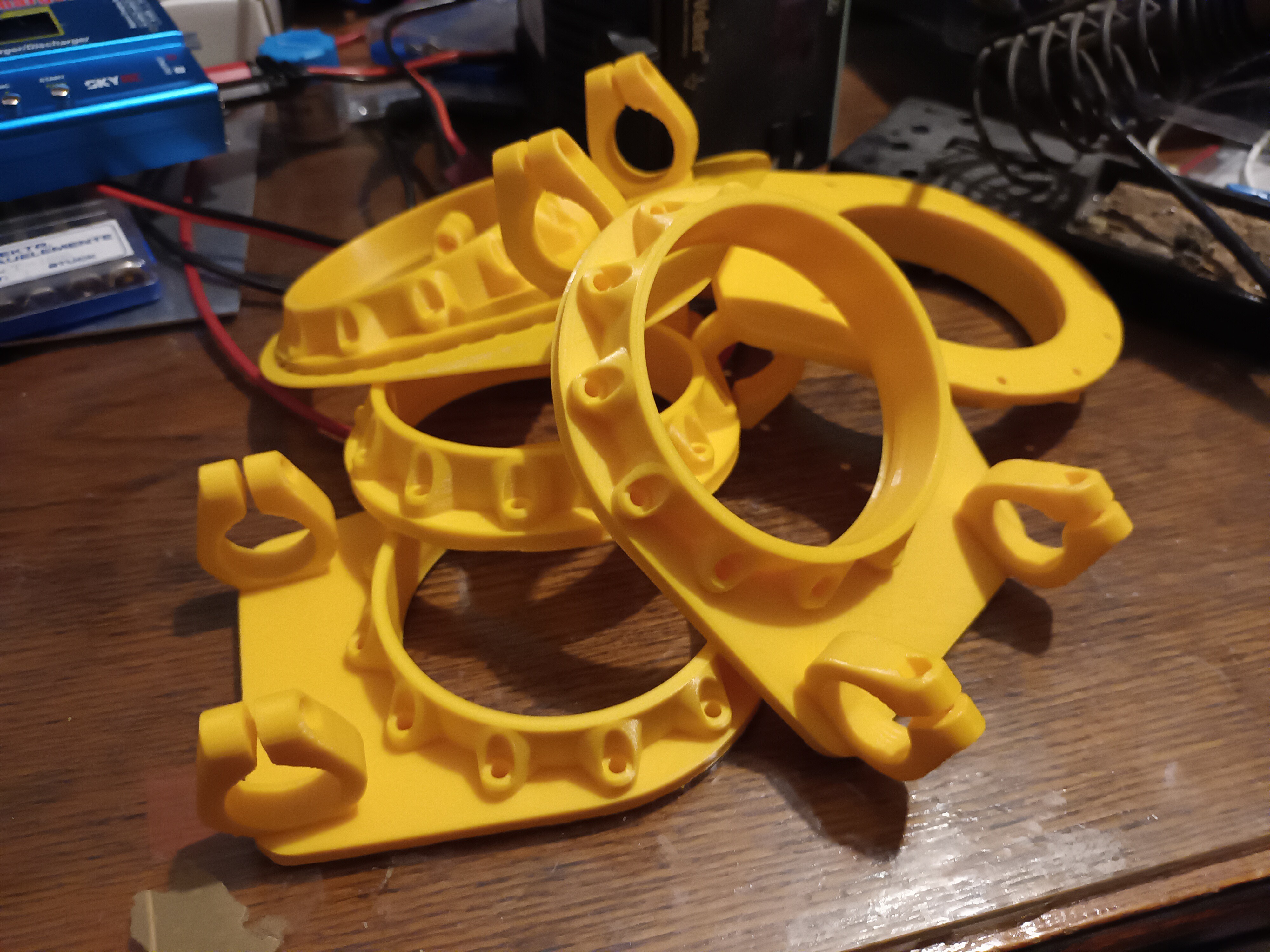
Fig. 1: Warped and shitty prints of the same part over and over again... gaaaa!! After that i did something productive and switched my focus to the rest of the electronics and software. As i wrote in my first log, the ROV will consist of two parts. The ROV itself and a Control Station above the water, which controls the robot via a tether. A block diagram can be seen in Fig. 2.
![]()
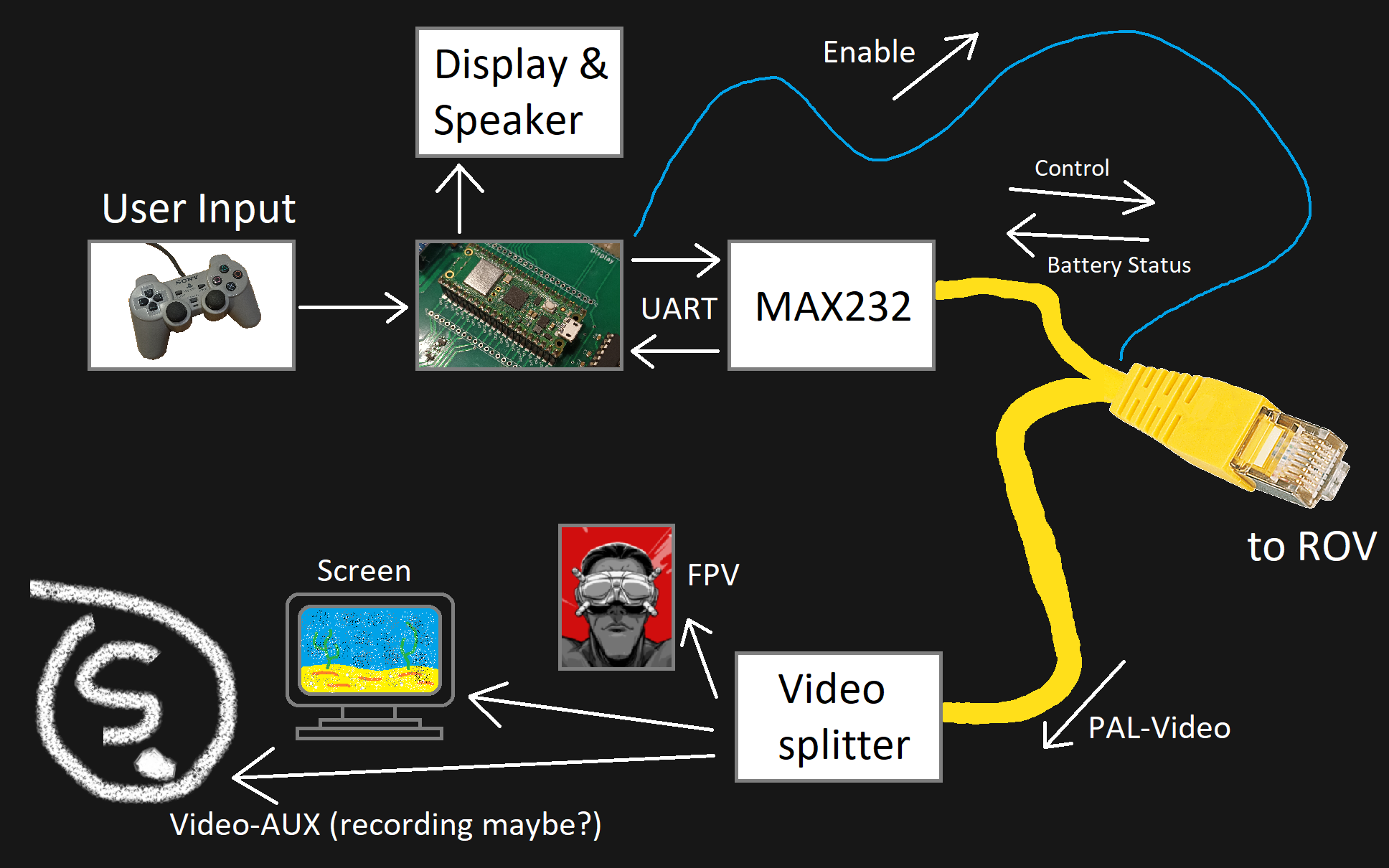
Fig. 2: Block diagram of the Control Station
Ok, what happens here? The User controls the ROV with a PS1 controller (no butchery required, i got the connector). The ROV steers via tank control, can point the camera in all directions and turn the light and camera on and off.A RPi Pico reads the user input and sends it via UART to the ROV. To only consume power when the ROV is operating, the TTL signal "Enable" is used to turn the ROVs battery off when the ROV is not operated. The ROV senses the battery voltage and sends it back via UART. So the user gets a rough estimate off how much power is left. The data will be presented on a small OLED display and a small piezo speaker will provide low battery warning.
Additonally the ROV sends back an analog video signal from the camera. The signal is buffered by a video splitter which can drive up to three different video receivers. A screen at the Control Station will show the video. Additonally an FPV transmitter (TS5828) will be connected which will send the video to FPV goggles. A third video output might be used for other purposes.
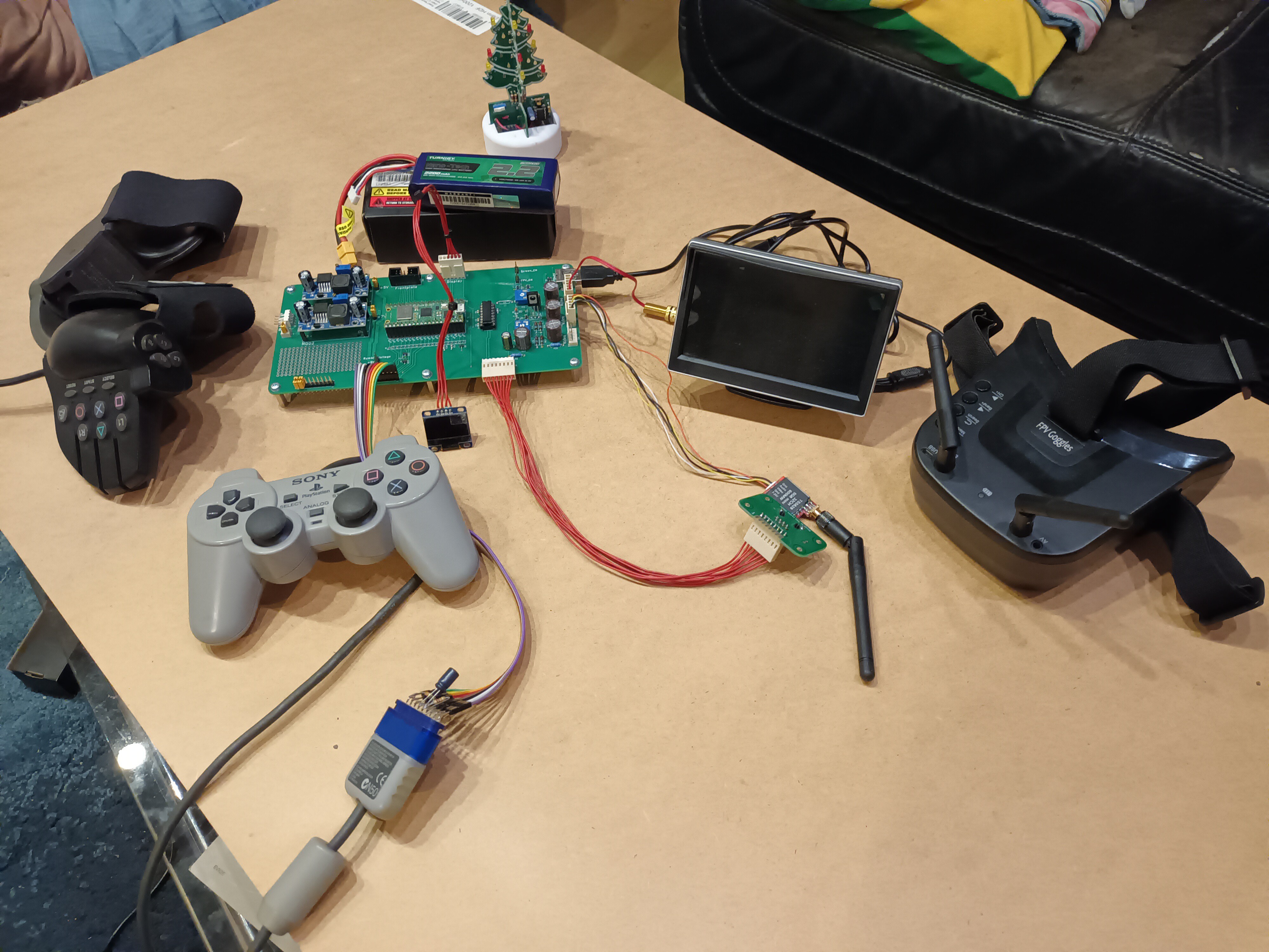
The hardware can be seen in Fig. 3.
![]()
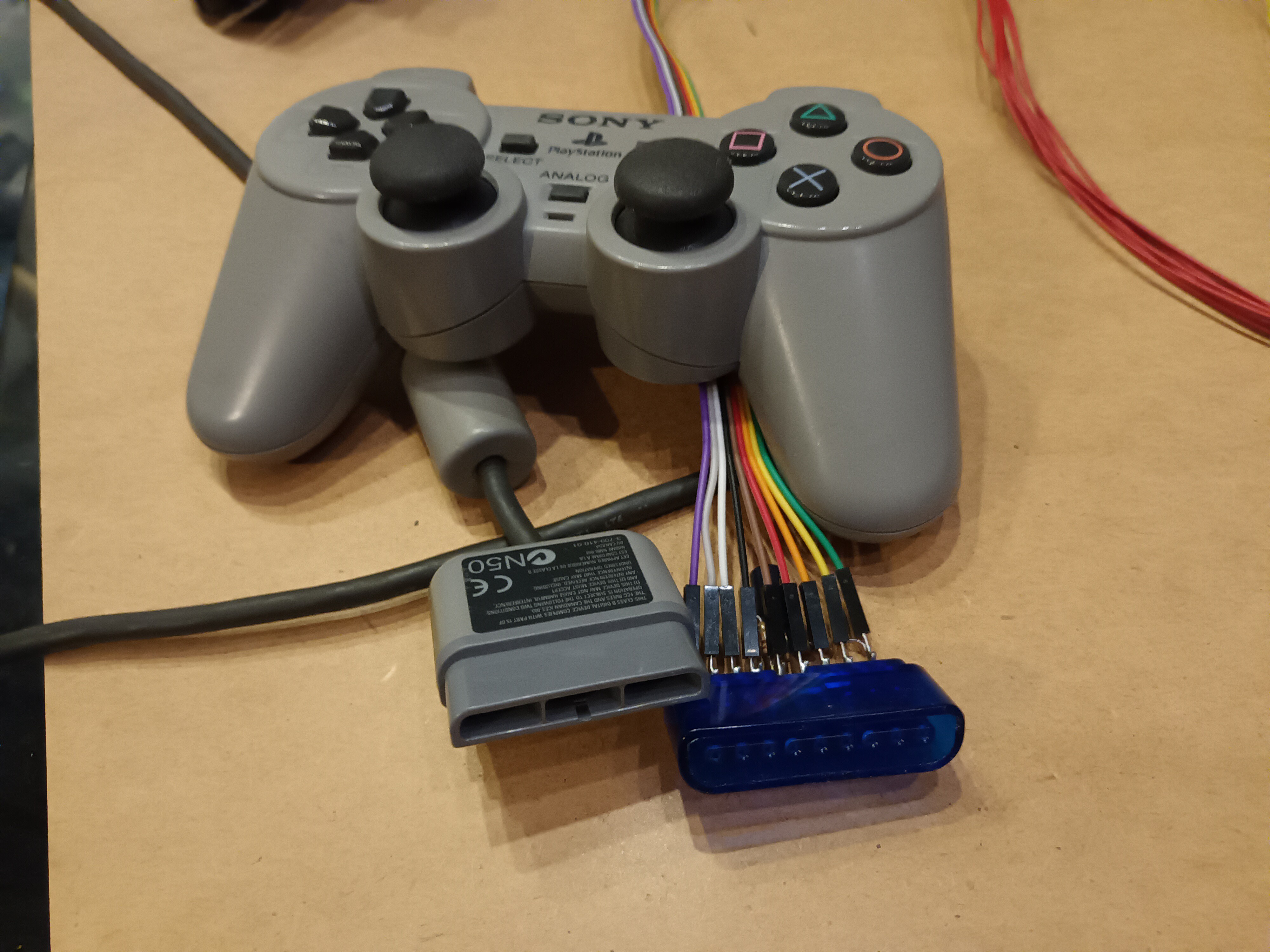
Fig. 3: More or less the whole Control Station (the piezo speaker is missing) Fig. 3. shows the whole Control Station. On the left you can see the PS1 controller. Instead of hacking of the connector or brutally violating an innocent PS1 like a heartless butcher, i was able the "aquire" a proper connector from a cheep PS1 to USB adapter.
Therefore i am able to change the controller and connect what ever type of obscure 90's gaming hardware i can dig up. One posibility can be seen in the picture.
On the left is the "PS1 glove" TM and i am not afraid to use it. It is sort of the answer to the NES "Power Glove". It is way cheaper and therefore If you want one, you can get it for 20 bucks on ebay. But there are also other possibilities, dance mat, flight stick, steering wheel and gas pedal, arcade stick.... some more suitable than others.
On the right you see a small CCTV screen and the chee.... most sophisticated FPV goggles i could get from AliExpress.
Power is provided via LiPo battery which is checked in the same way as the ROV's battery.
![]()
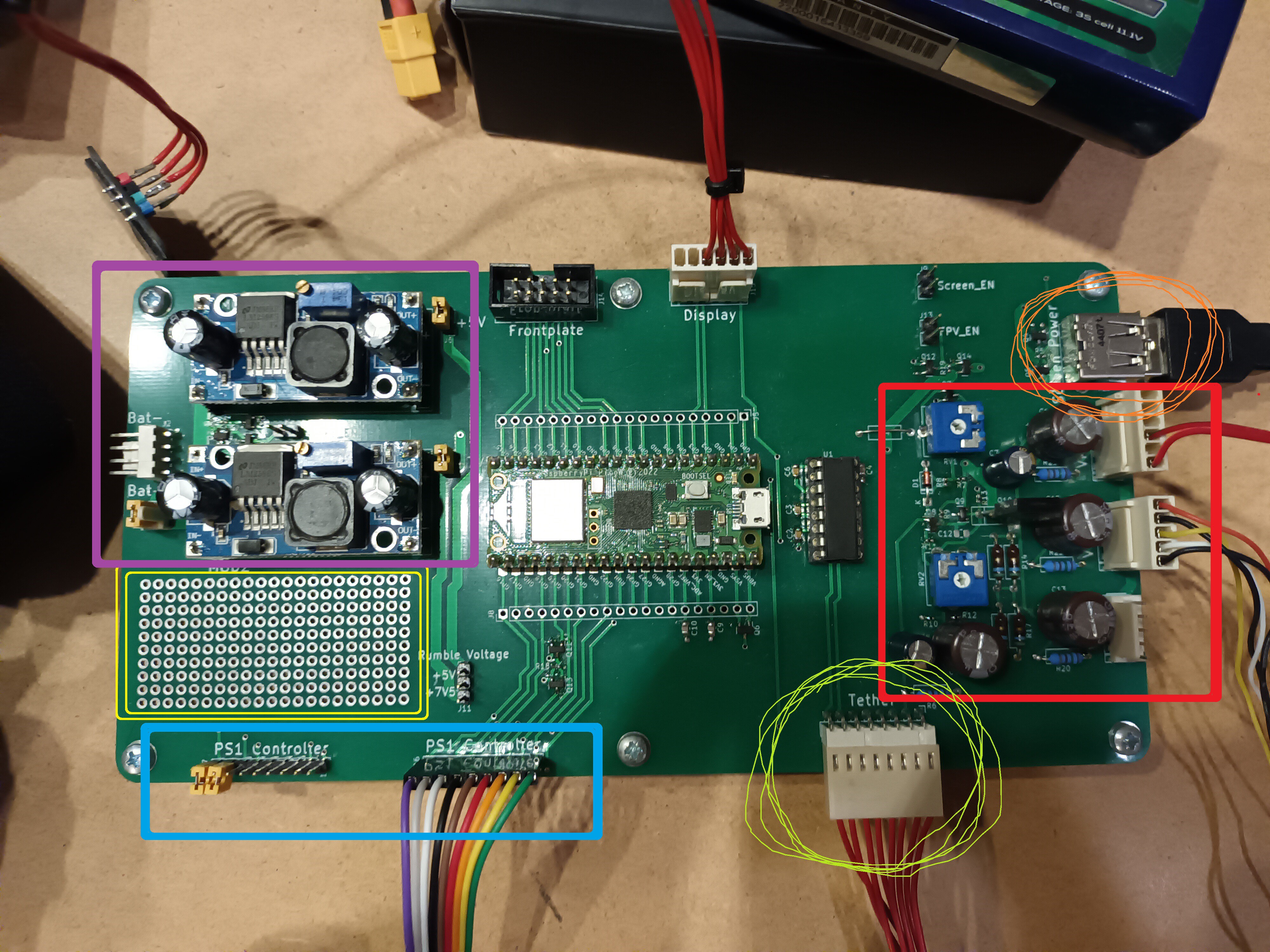
Fig. 4: PCB of the control station. violet: power supply, blue: 2x PS1 controller, green: connection to tether, red: video splitter with three identical outputs, orange: power supply for CCTV screen, yellow: panic grid for last minute addon's In Fig. 4. you can see the pcb of the Control Station. The power supply generates +5V (digital) and +7,5V (analog). The Pico generates +3,3V for himself, the OLED display and the PS1 controller. There will be a main power switch, but at the moment it is replaced with a jumper.
In total there are two connectors for PS1 controllers, but at the moment only one is in use. For future updates it might be possible to have a teacher-student-mode or something. But only the right controller can rumble. Yes, i connected that as well ^^.
The video splitter has three identical outputs, so it is not important what is connected to which connector, so there are no special markings.
The CCTV screen needs +5V power which is provided via a (power only) USB connector. The screen can be turned off to save power if it not needed. Same goes for the FPV transmitter who is greedy and power hungry.
![]()
Fig. 5: perfecly fine and healty PS1 controller. No sick butchery required The Software for the ROV and the Control Station are written in Micro Python. A short demonstartion is given in this video. It is not perfect, or good, or acceptable... The gimbal is moving in a stuttering motion due to "creative number handling".
Also some part of the comunication between ROV and Control Station is mixed result, when the 3 cell Lipo is suposed to have 22V. But the basic function is there.
-
Watertight Compartment (WTC)
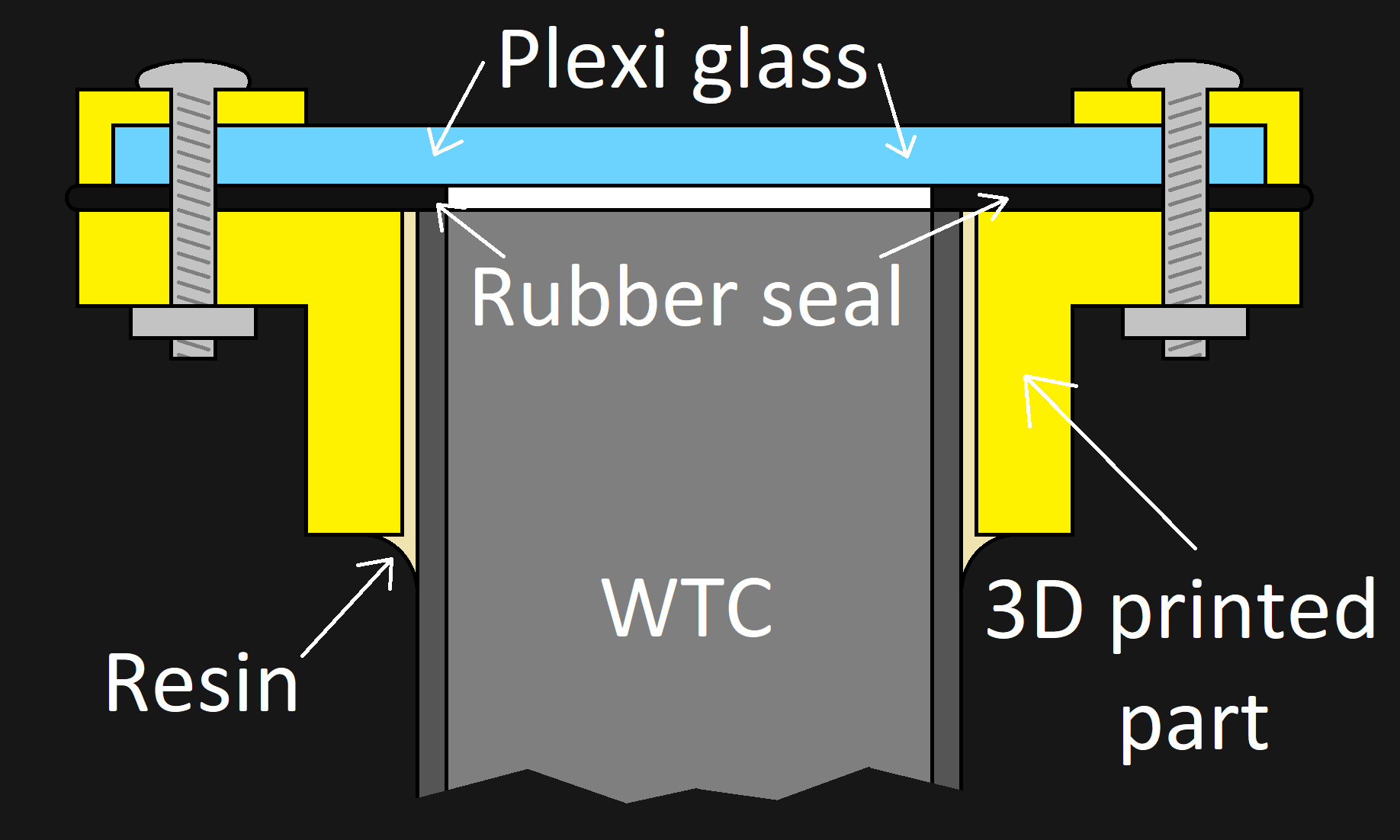
10/31/2022 at 21:18 • 0 commentsThe next step in the project will be to make the electronics not go dead when they are put into water. The idea behind what i want to build can be seen in Fig. 1. Both ends of the WTC will be closed like this.
![sketch of WTC and seal sketch of WTC and seal]()
Fig.1: This is a sketch off how i plan to implement the "WT" in WTC One disadventage of 3D printed parts is, that they are not watertight. Because off how a FDM printer works the parts have small cavaties inside and under preasure the water will push through in seconds.
A 3D printed flange (yellow) is glued with resin to the WTC (grey). On top of that is a rubber seal. It covers the entire flange and the wall of the WTC. Several screws push a piece of plexi glass which acts as a bulk head down on the rubber seal and on the wall of the WTC, forming a watertight seal without relying on the 3D printed part to be watertight.
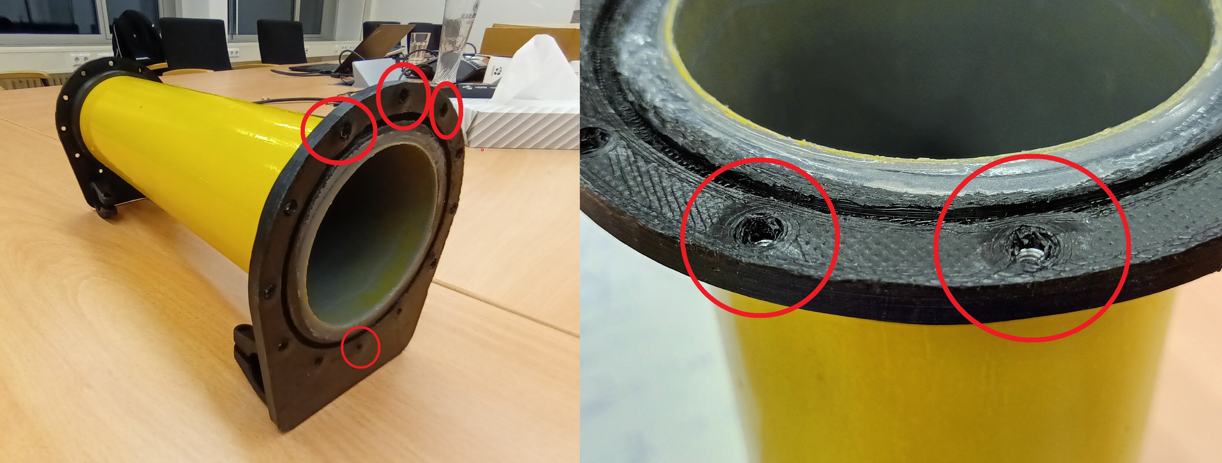
The first failed attempt can be seen in Fig. 2.
![First try to make a watertight compartment First try to make a watertight compartment]()
Fig. 2: First failed attempt to make a WTC. The red cicles show where the 3D printed part failed Although it worked at first, the force from the squished rubber seal tore the 3D printed part apart. ( It is totally impossible that i over tightened the screws. I am perfect! ) For the second attempt i changed the infill from 30% to 100% to have some more meat and i used heated inserts instead of loose M3 nuts. The new part can be seen in Fig. 3.
![Second prototype Second prototype]()
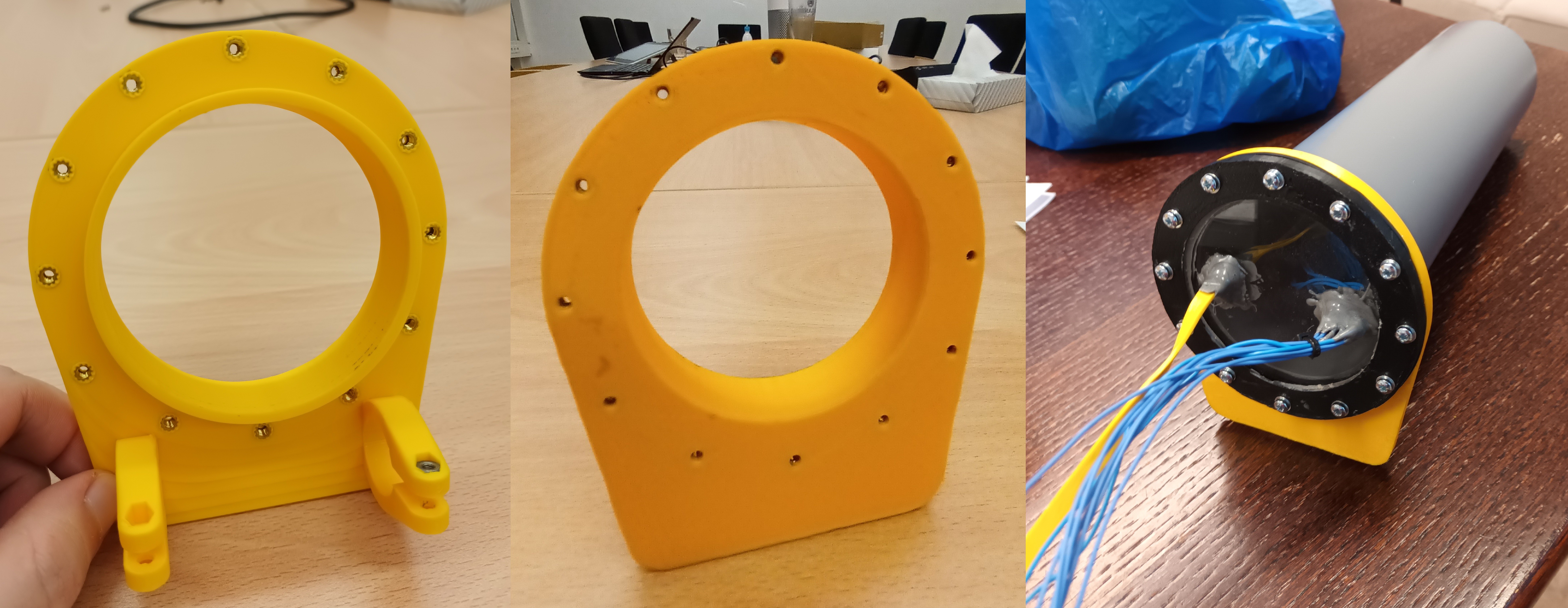
Fig. 3: backside and frontside of the second prototype and glued on the WTC with seal and plexi glass mounted ( from left to right ) To get the tether inside and the motor leads outside of the WTC there need to be some holes in the bulk head. My best plan is "just use al lot of resin", which totally worked out. ( No really, no problems at all. No sarcasm. I mean it.)
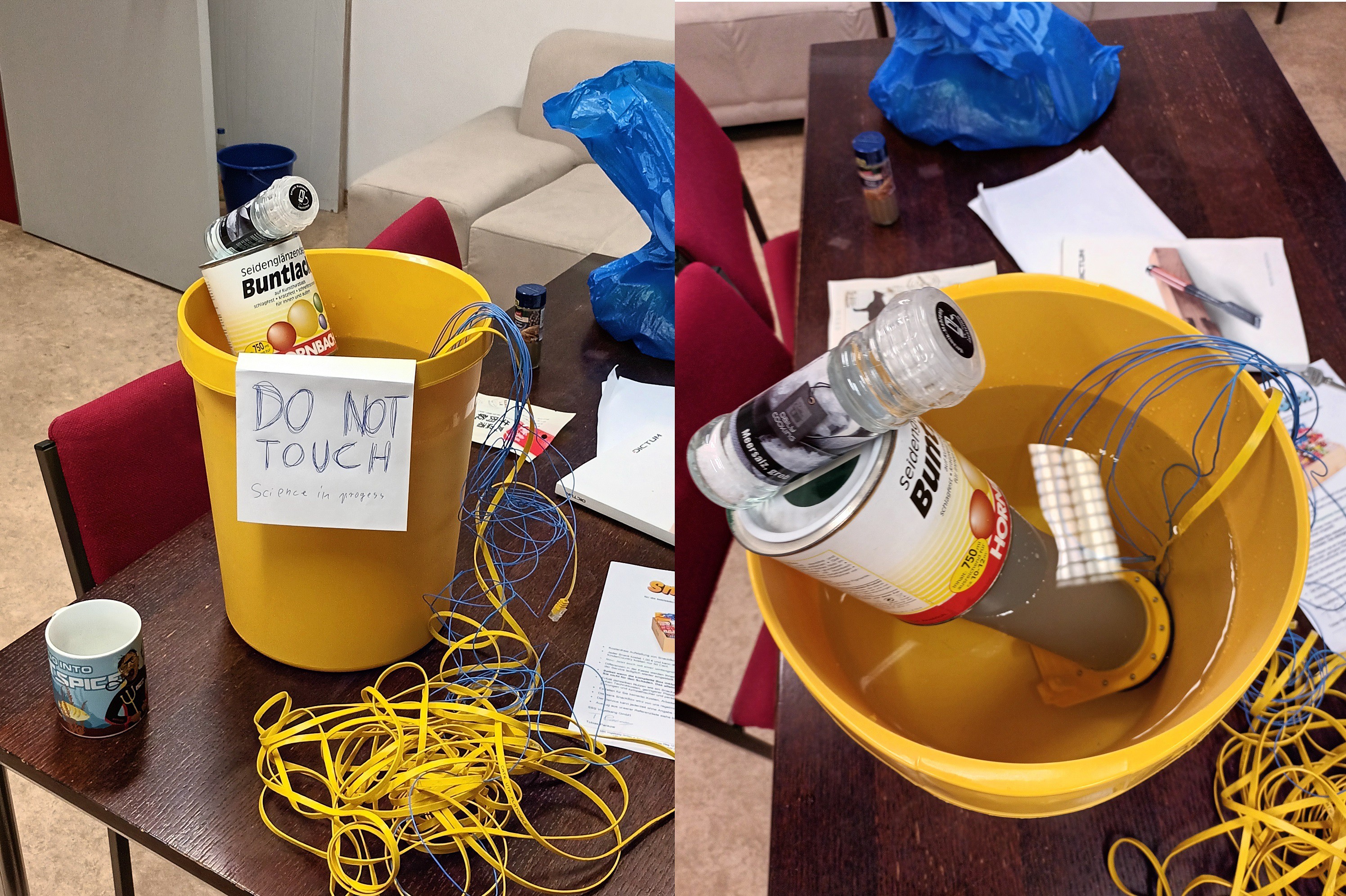
To test the the WTC i submerged it in a ( mighty science ) bucket of water as you can see in Fig. 4. The WTC was weighted with a science grade can of paint to keep push it under water. I checked after 30min, 1h and 2h. No leak was detected. ( And yes, the salt shaker is important. )
![Hail science bucket!! Hail science bucket!!]()
Fig. 4: WTC submerged in the science bucket with weights to push it under water.
This seams to work now, so i will add the second bulk head. -
Electronics II + Mechanics I
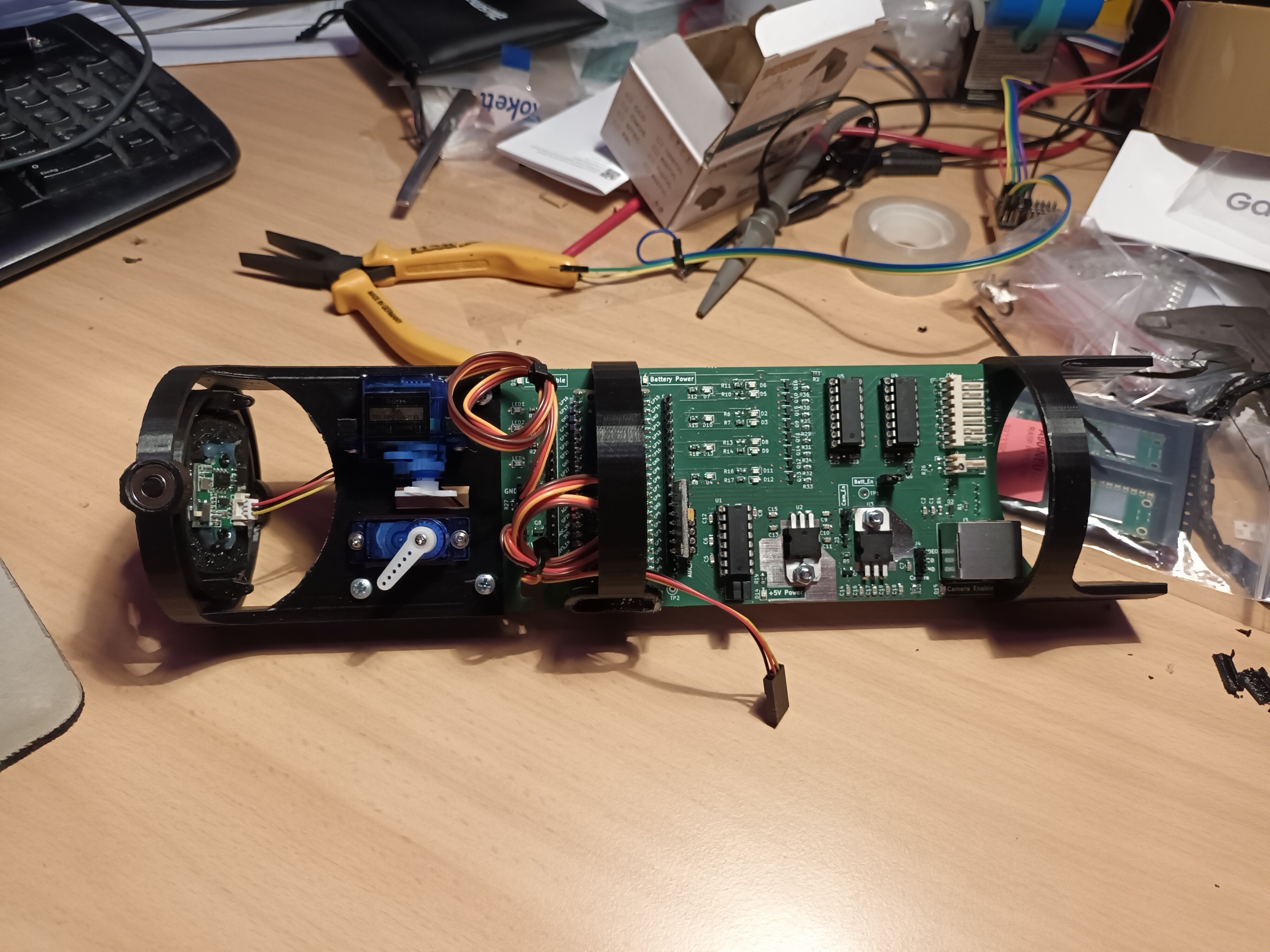
09/21/2022 at 20:44 • 0 commentsThe pcb arrived! And i populated it. Here you can see the board. I already added some 3D printed parts like the camera gimbal and the mounting brackets.
![]()
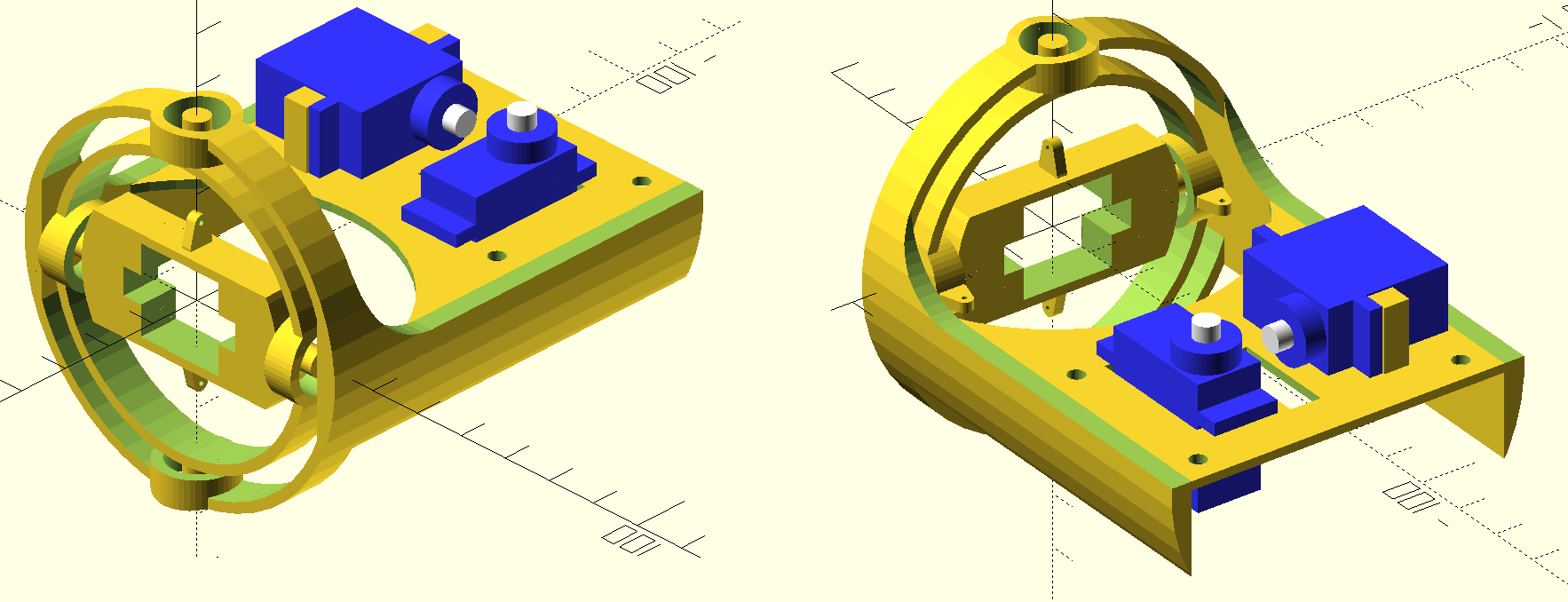
I designed all parts in OpenSCAD. The watertight compartment (WTC) is made from a drain pipe from my local submarine dealership/home improvment store. The gimbal has the same diameter and also acts as a mounting bracket for the pcb.
Behold:
![]()
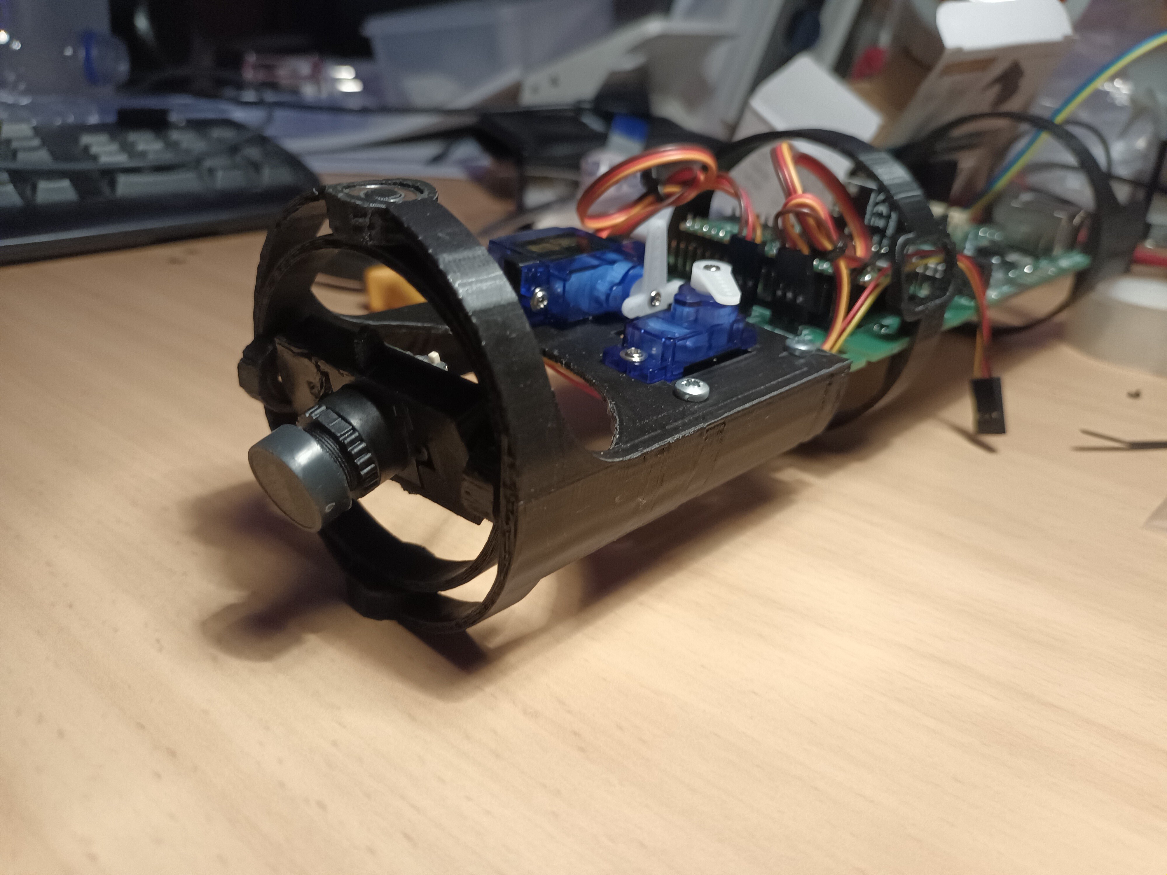
Here you can see a close up of the real part. The camera is already fitted. As joints between the 3D printed parts i used ball bearings.
![]()
-
Electronics I
07/14/2022 at 01:42 • 0 commentsThe schematic of the main electronics on the PCB can be seen here:
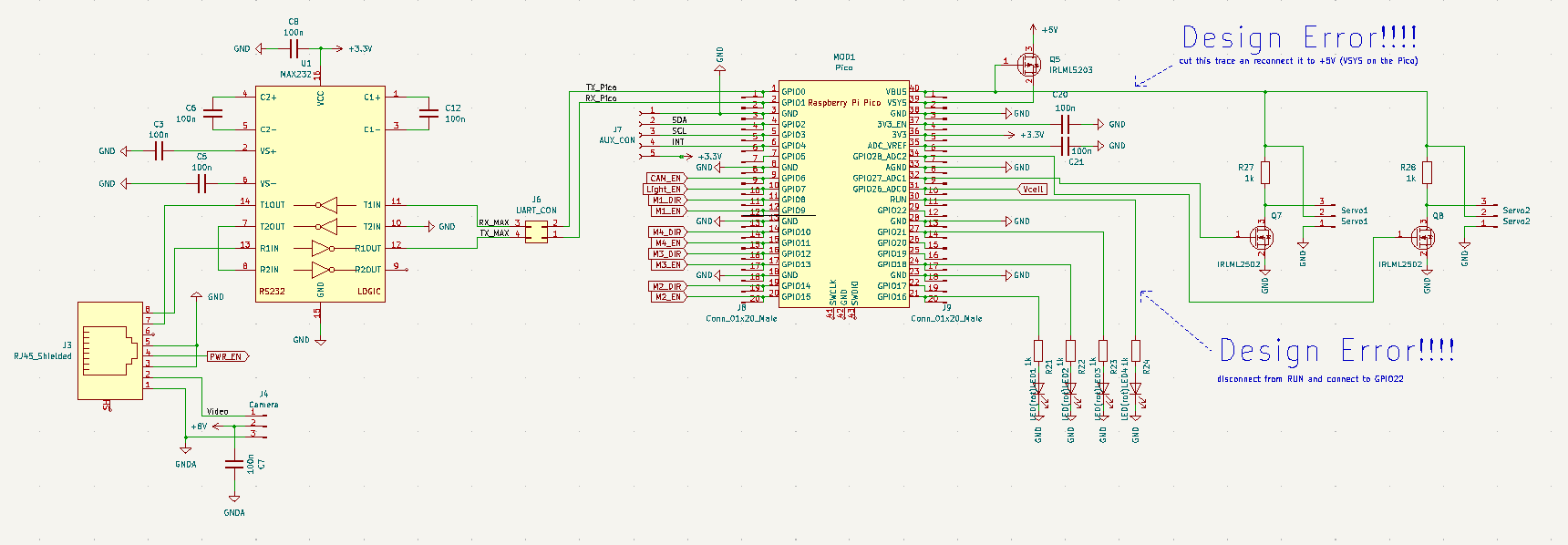
![]()
A RJ45 jack is used to connect the tether to the PCB. The TX and RX trace are connected through a MAX232 to a RPi Pico which controls everything. The Pico controls the thrusters through motor drivers (L293, not visible here) and two SG90 RC servo motors for turning the camera gimbal. Additionally a 4 LED debug light and an auxilary I2C bus are connected to the Pico and some day i might find an Application for that. Luckily i already ordered the pcb, so i dont have to fix the parts which are marked with "Design Error !!!!". Again, success!
![]()
The tether also carries a signal which controlles a PMOS FET to disconnect the battery so i can turn the hole thing on and off without disassembling it. Additionally there is a voltage divider to reduce the battery voltage by roughly a factor of 5 and feed it to the adc of the Pico. If it gets too low i will probably do something with that information.+5V power is provided by the finest LM7805 my junk bin could offer.
The video signal is generated by an RC FPV camera. Signal and separate video-gnd go through the tether as well. The +8V power for the camera is provided by a separate LM7808 to completely separate the noisy digital- and servo-supply from the camera supply. The camera supply can be turned on and off because the camera eats a lot of power and should be turned off when ever it is not in use.
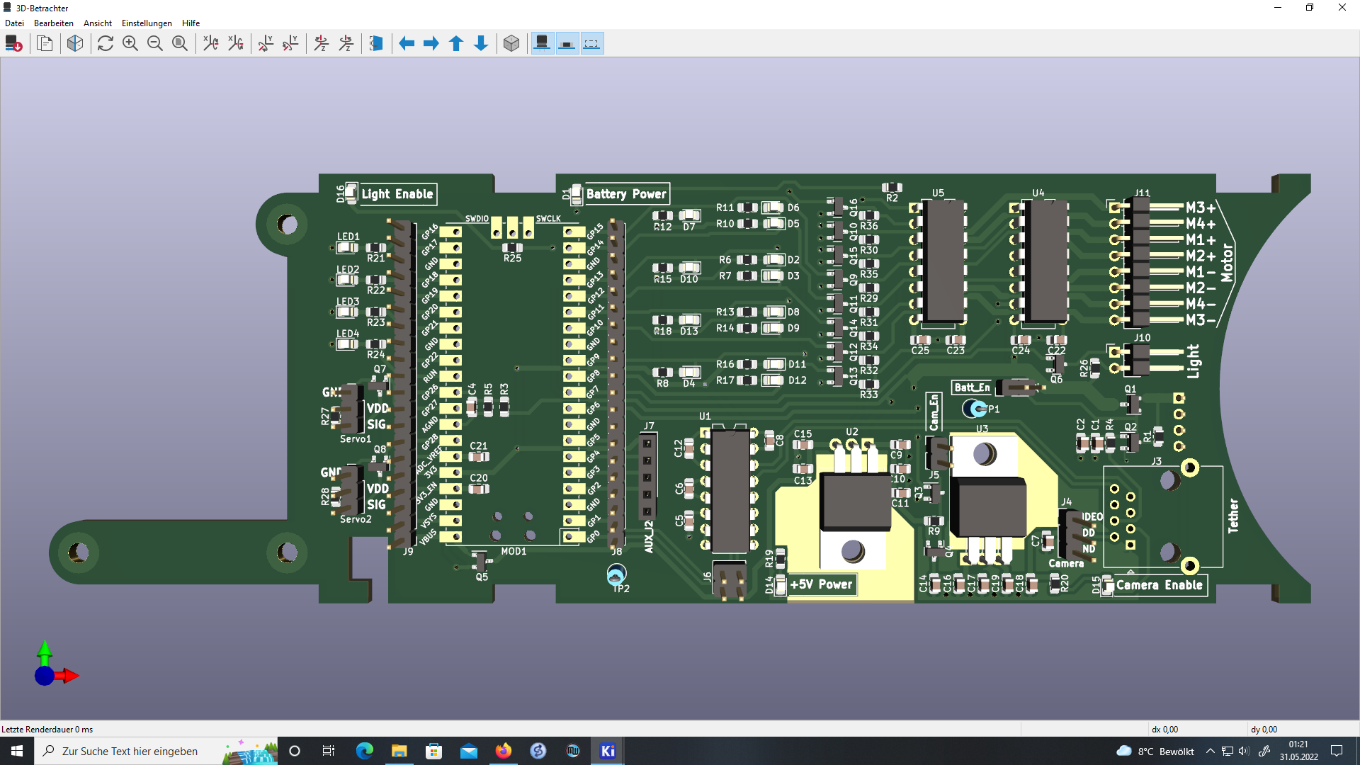
This is how the render of the PCB looks like:
![]()
-
Concept
07/14/2022 at 00:35 • 0 commentsThis is the concept of the ROV
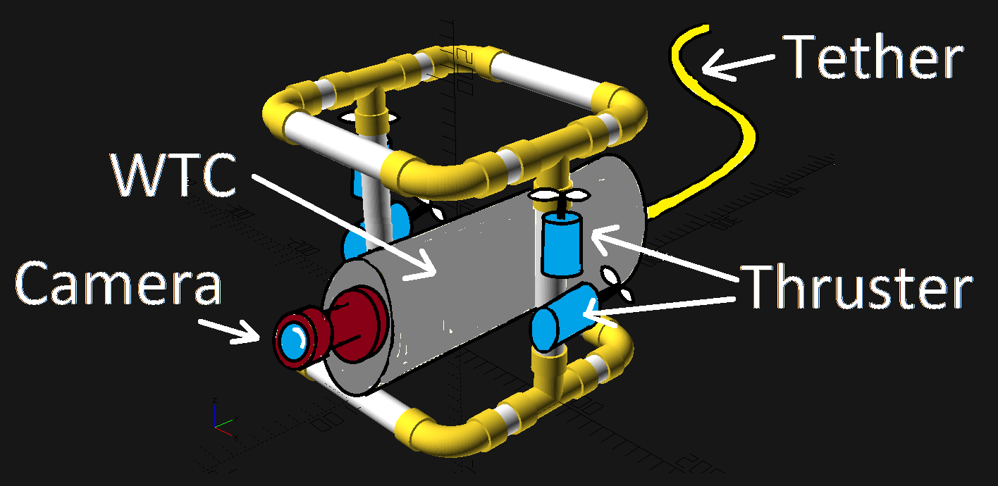
![]()
It will look like any other DIY ROV. The Water Tight Compartment is mounted on a frame which keeps everything together. Two thrusters push the ROV below water and control the depth. Two additonal thrusters provide forward and backward thrust as well as differential steering.In the front of the ROV will be a camera. To provide a good view for the operator the camera will be mounted on a gimbal in a plexi dome.
The analog video signal will be linked to the water surface through the tether. Steering comands will be provided through the tether as well by means of RS232. Power will be provided by the on board battery to prevent large voltage drops across the tether. This will also keeps the tether from being thicker than my ... arm. What did you think?
The other end of the tether will get some love when i am done here.
Turbo Super Submarine
A simple ROV i can use to dive to the deepest depths of my bathtub and my neighbor's swimming pool
 Timo
Timo