Guido
Guido-
Graphical User Interface
12/29/2022 at 21:11 • 0 commentsMy first will was to embed everything in the Zynq7010 FPGA to show its wonderful capabilities.
However I'm still in trouble to find the best way to do it!
For brainstorming, I can try a little resume of the features I want (ed):
- wide band (0-30 MHz) radio spectrum
- zoomable (30MHz ... 10 KHz) radio spectrum and waterfall
- listen to AM/USB/LSB demodulated station
- IF bandwidth selection (1 - 32KHz or more)
- FT8 decoding and sending to https://pskreporter.info/
and the possible human interfacing solutions could be the followings.
- standalone:
- LCD screen connected to HDMI (not present on EBAZ4205)
- Loudspeaker connected via I2S
- switches, commands, frequency selector ... via GPIO
- WEB (like KIWI SDR):
- spectrum and waterfall on the web page
- audio streaming on the web page
- switches, commands, frequency selector ... on the web page
- PC software (like HDSDR, SDR#, ...)
Any suggestion?
-
Ready to receive HF Radio Stations
12/29/2022 at 20:37 • 0 commentsNow almost everything is ready to receive HF Radio Stations.
- ADC: done
- sampler: done
- spectrum viewer: done but not mandatory for listening
- Digital down converter: done
- CIC decimator - FIR filter: done
- AM demodulator: done
- SSB demodulator: TODO
- AGC (*)
- I2S output: done
(*) designed and simulated but not tested yet
After a few attempts, using a simple C++ program running on Linux in the Zynq Programmable System I set:
- IF GAIN = 4
- CIC decimation = 1024 corresponding to an audio bandwith of 8KHz
- Mux switched to Test Generator
- Test Generator at 10 MHz (1 KHz Amplitude Modulated)
- Local Oscillator at 10 MHz
and obtained a clear 1KHz tone at the output of the PCM5102 I2S ADC (around 1,5 Vpp),
Then I successfully tried a few Radio Stations after verifying they were receivable at that time using http://kiwisdr.com/public/
- IF GAIN = 4 (up to 64)
- CIC decimation = 1024 corresponding to an audio bandwith of 8KHz
- Mux switched to ADC (don't forget to supply the ADC and connect the antenna)
- Local Oscillator at the frequency of the chosen Radio Station e.g. 7215 KHz for China Radio International (English)
-
Test Signal Generator
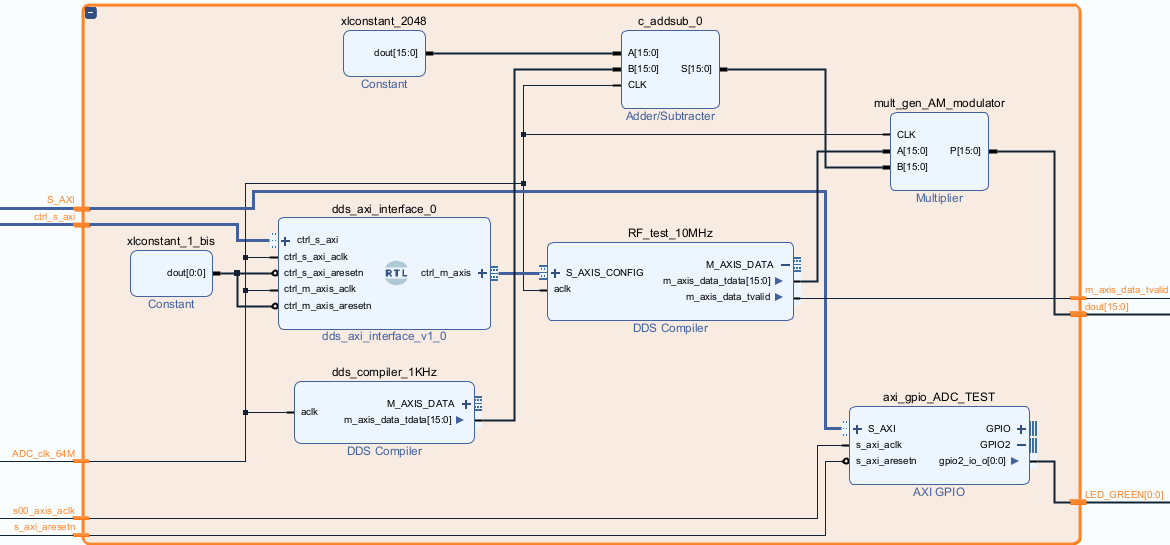
12/29/2022 at 18:26 • 0 commentsTo test the fabric logic and the whole design even without an external signal and without involving the ADC, I rapidly understood the need of an internal test signal. Using a Xilinx DDS compiler IP I designed the following block:
![]()
The RF_test_10MHz generates a sinusoidal signal from 0.1MHz to 30MHz (default 10MHz) and programmable by dds_axi_interface_0.
The dds_compiler_1KHz generates a 1KHz 12 bits sinusoid (-2048 ... 2047) added to a 2048 constant value to obtain a 12 bits sinusoid between 0 and 4095.
The 1KHz sinusoid then multiplies (AM modulates) the test sinusoidal signal (e.g. at 10 MHz) obtaining the desired AM modulated signal roughly between -2048 and 2047 i.e. 12 bits after right shifting inside the multiplier.
-
Signal levels at any stage
12/29/2022 at 18:03 • 0 commentsTo keep the "right" digital level at every stage of the SDR looks quite challenging to me.
"Right" means:
- enough high to reduce numerical noise
- enough low not to saturate the two's complement fixed point numbers
To test and simulate such a level in any stage (complex multiplier, CIC, FIR etc.) I designed the test generator so that it outputs the maximum peak to peak signal level, which at 12 bits is between -2048 and 2047. This is the same maximum signal level the ADC can handle before saturating.
Then I designed every following stage to output the maximum output level given the maximum input level. For example, see the complex multiplier.
-
AM demodulator
12/20/2022 at 17:17 • 0 commentsAfter seeing the very good result I obtained designing and simulating the AGC using matlab - simulink, I decided to complete the logical path from RF to audio, designing an AM demodulator.
In this way I could listen to some radio stations at last. I read some articles on the web but the only one I found really interesting is "An FPGA SDR HF Transceiver by K6JCA" who very well describe the AM demodulator.
A little resume, now I have the following items:
- ADC: done
- sampler: done
- spectrum viewer: done
- Digital down converter, CIC decimator - FIR filter (*)
- AM demodulator (*)
- SSB demodulator: TODO
- AGC (*)
- I2S output: done
(*) designed and simulated but not tested yet
So I'm almost ready to put it all together in my EBAZ4205.
Talk to you soon!
-
AGC - Automatic gain Control
12/19/2022 at 11:49 • 0 commentsMaybe I could postpone its design, but I just learn Matlab Simulink a little, so I decided to test my new skills.
I found this interesting article Design and implementation of a new digital automatic gain control by Etienne Tisserand, Yves Berviller describing the forward AGC control, so I decided to adapt this solution to my requirements:
- sampling rate = 48000 Hz
- data format = 32 bit two's complement
- dynamic range > 40 dB
- Adjustable Attack and Decay
I simulated on Simulink and created a VHD function to be used in Vivado.
-
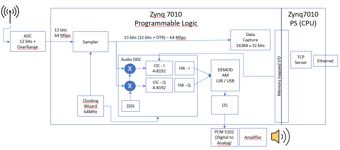
I2S Audio Output
12/10/2022 at 19:02 • 0 commentsAs I told before, I'm in the mood to tune any HF radio station and therefore I need to get some audio out the Zynq-7000.
![]()
To get some audio out of the Zynq I examined a few options:
- send the audio stream to the PS (via DMA or Data Capture) and then:
- from PS to a Python client (the same I'm using to display the wide spectrum) via a web socket stream
- or from PS to a DAC via I2S
- get audio as a digital stream from the PL (via I2S standard) to a DAC (PCM5102 or similar)
- get audio as a PWM from the PL (as Raspberry does)
In the future I'd love to avoid the use of an external PC, so I discarded 1a
I discarded 3 because the audio quality is not excellent and you can hear some "clicks"
I discarded 1b because I'm not very fond of linux drivers and it is not very clever to move audio from PL to PS and then back to PL
Therefore the winner is: get audio as a digital stream from the PL (via I2S standard) to a DAC (PCM5102 or similar):
- I2S is a standard
- several very cheap I2S DAC exist (PCM5102, MAX98357, ...)
- I found a Vivado IP that worked immediately. See I2S in the Details.
- send the audio stream to the PS (via DMA or Data Capture) and then:
-
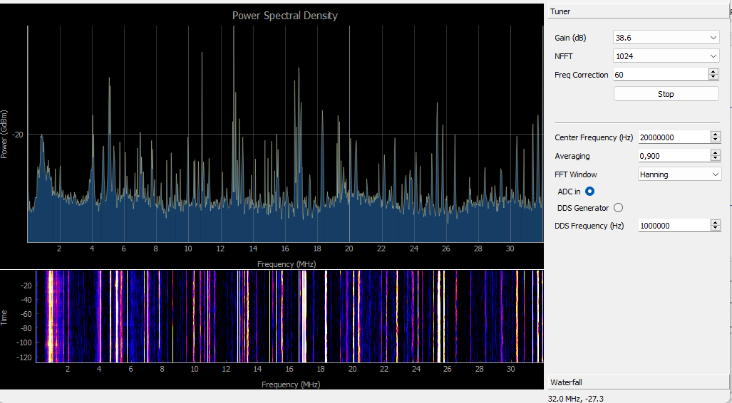
First spectrum and waterfall result
11/16/2022 at 18:28 • 0 commentsAs you can see in the following picture, with my first assembly I received many signals in the full 0-32 MHz band simply connecting my EFLW antenna directly to the analog input.
I'm pretty sure that a few of these signals are entering the receiver from the 2nd and 3rd Nyquist zone but I'm not sure because I cannot demodulate them at the moment.
Anyway in my opinion this first result encourages me to go on!
(Y-axis not in scale)
![]()
-
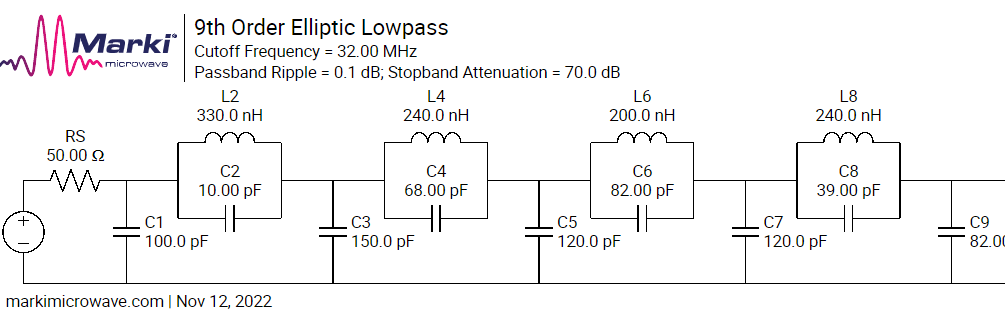
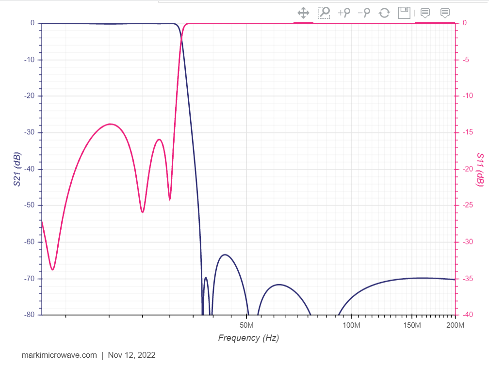
Low Pass Filter
11/12/2022 at 07:43 • 0 commentsAccording to Crun suggestions, I would try to build a lowpass filter like this:
![]()
![]()
-
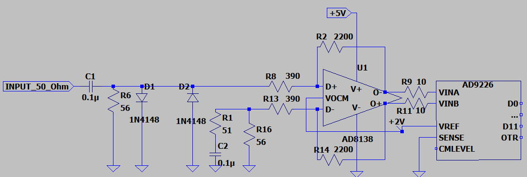
ADC board modified
11/09/2022 at 19:55 • 0 commentsTo get some amplification, I modified the circuit in this way:
![]()
Now the overall amplification between VINA-VINB and INPUT_50_Ohm is approximatively:
(2200/390 + 1) = 6,64 i.e. 16,5 dB 16,5+8,4= 24,9dB better than the original!!!
Of course I lost bandwith, but it still remains flat well beyond 30MHz.
Please note that I also DC decoupled the input, to avoid that DC short circuited antennas (e.g. EFLW with BALUN) or power supplied antennas (e.g. Magnetic Loop or Mini Whip) could influence or damage the analog input.
32MHz spectrum + SDR + FT8 in an FPGA
A 0 - 32MHz FPGA based Software Defined Radio (AM SSB FT8) by ready modules->cheap and easy Last add: Aug 14th SW update to include GFSK