 Jeremy
-
11Power test the new control boards for the 3D printer.
Partially place the electronics cabinet back into the back of the 3D printer.
Reconnect the power, Z-axis, X-axis, Y-axis, thermocouple, and all other connectors to the electronics cabinet.
Slide the electronics cabinet fully back in to the back of the 3D printer.
Plug in the power cable to the electronics cabinet.
With the electronics cabinet still open so the Duet boards are visible, plug the power cable into the wall and turn of the power switch to the printer.
Ensure no "magic smoke" was released and the Duet and Geckodrive boards and the LED light strip have power as indicated by some of the LED lights turning on.
If all is ok, turn off the power, remove the power cord from the wall and the back of the printer and proceed to the next step.
-
12Copy the DuePrint configuration files to the Duet 2 WIFI.
Download the SD card contents (zip file) from the Hackaday project.
Unzip the zip folder.
Navigate to the config file and open it in notepad or Notepad++.
Modify the line containing the WIFI SSID and password to enable the printer to connect to the internet. This is to enable the use of the Duet Web Control. (More information can be found on Duet3D's website.)
Also modify the password for connecting to the printer in the Web Control software.
Save the file. (Overwrite if prompted.)
Remove the SD card from the Duet 2 WIFI board.
Copy the folders containing all of the files for the DuePrint to the SD card on a PC. Overwrite all prompted files.
Insert the SD card into the Duet 2 WIFI board.
Reconnect the power cable and power on the 3D printer.
Open the network page on your router and find the IP address of the printer. Again Duet3D's website contains useful information on how to do this.
Type in the IP address in the internet browser and the DWC software will open.
Type in the password entered earlier.
The software should now load all of the settings for the DuePrint.
-
13Test the X, Y, Z motors and end stops.
If everything worked correctly you should now have control of the movement motors and end stops.
Manually move the print head to the center of the printer.
Next, the axes homing will be tested to ensure the motors are wired up correctly. Be prepared to quickly click Emergency Stop.
Press home X.
If the head moves to the left of the 3D printer then everything is OK. Otherwise either swap a + and - on the motor connection to the Duet or modify the config file following the instructions on Duet3D's website. Repeat if necessary.
Press home Y.
If the head moves to the front of the 3D printer then everything is OK. Otherwise either swap a + and - on the motor connection to the Duet or modify the config file following the instructions on Duet3D's website. Repeat if necessary.
Press home Z.
If the build plate moves to the top of the 3D printer then everything is OK. Otherwise either swap a + and - on the motor connection to the Duet or modify the config file following the instructions on Duet3D's website. Repeat if necessary.
I broke the z-probe lever on the back of the head, so the config file may need to be modified to allow for the extra length. It can be a challenge to move the head to the exact right position and not crash against the U shaped protrusions in the back of the inside of the printer. These are needed for switching the toggle head as well as the Z-probe which is used for bed leveling and as the Z-endstop.
-
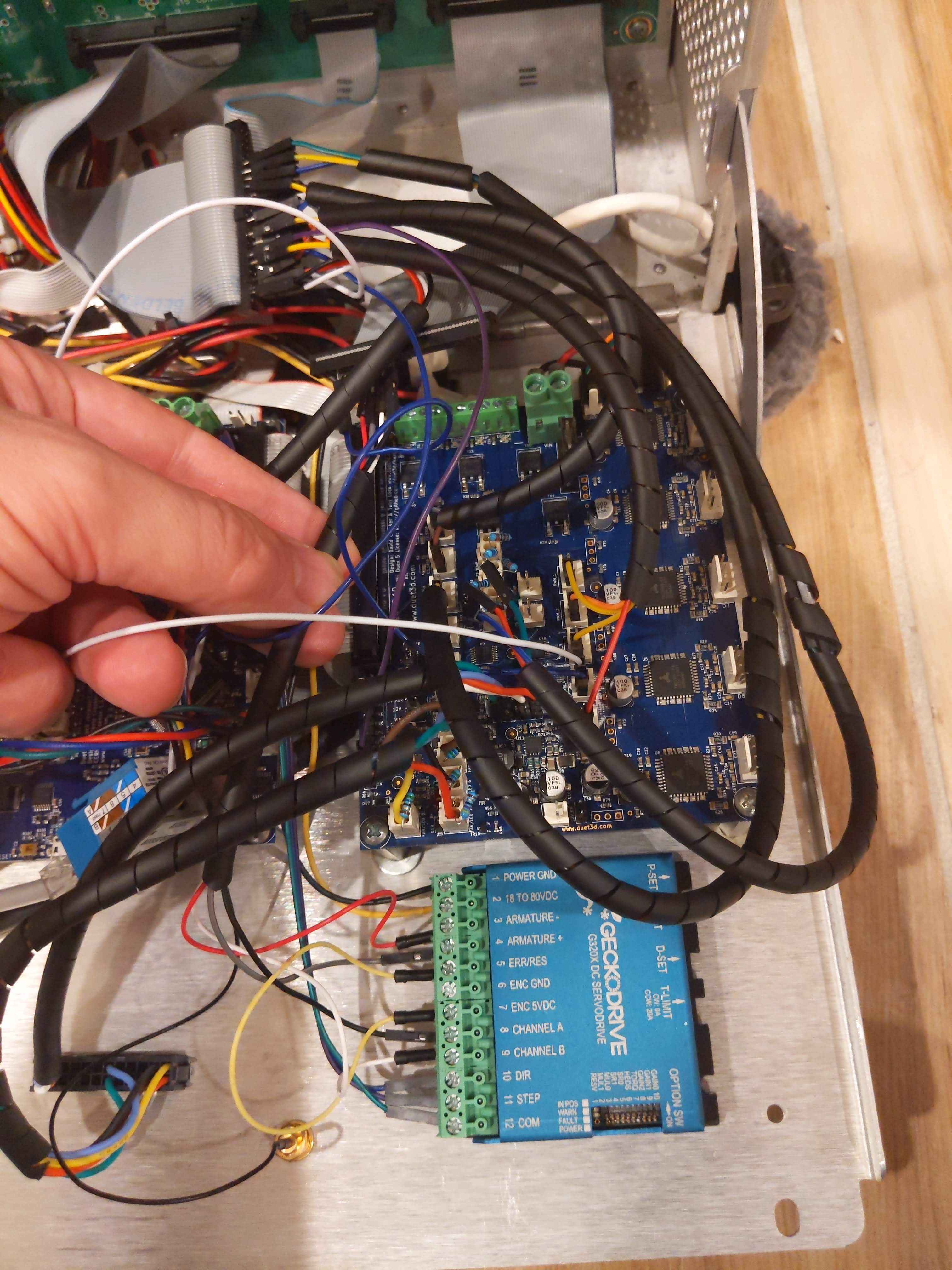
14Go through the process of connecting the Geckodrive G320X DC servo motor driver.
![]()
Follow closely the steps outlined on Geckodrive's website for connecting the extruder motor and encoder to the Geckodrive.
Start by connecting and testing the encoder by connecting the J13 (DuePrint PDB) encoder wires. Ignore the encoder power since the encoder is already powered through the PDB. Be sure to connect terminal 5 to terminal 7.
To test the encoder, remove the plastic cover on the print head by pressing in on the tabs on both side of the head and gently pull on the clear plastic cover,
With the cover removed, use a small screwdriver and slowly press on the set screw on the extruder motor to move it slightly out of position. Another set of eyes may be helpful to see the changing LED lights.
Once the encoder shows it is working, power of the printer and connect the STEP, DIR, and GND (to COMM on the Geckodrive) pins on the Duet 2 WIFI (Step 10, dir 10). Power on the printer.
With the axes homed, send an M302 P1 command to enable cold extrusion and then send an extrude command and the fault light should light up as indicated in the Geckodrive G320X manual. Note the motor is not powered at this point and will not move.
Power off the printer and connect the + and - armature to the extruder PWM#1 and extruder PWM#2 points on the J13 connection.
Power on the printer.
Send an M301 P1 command to enable cold extrusion.
Send and M42 P3 S1 command to enable the extruder motor on the PDB. There should be a buzzing noise when the M42 command is sent. This noise is the encoder working on keeping the DC servo motor in the correct position.
Then send an extrude command using the DWC buttons. The motor should turn. For tool 1 (left tool - support) the extruder should move counterclockwise when extruding. When the tool 2 is used it should turn clockwise when extruding. For now, if the motor moves then everything is working. Once the heaters are tested then clicking on the different tools should switch the direction automatically and the motor direction can be fixed either programmatically or physically with reversing the wires to the J13 connector.
-
15Test Heaters and Tune if necessary
Now that all of the motors are working now it is time to test the heaters.
Begin by testing the chamber thermocouple.
On the PDB there are test points for the thermocouples. Every 10 mV = 1 C.
Check the test point to make sure the chamber thermocouple is reading around room temperature.
Heat up some water. Hot tap water should be fine.
The side panels on the printer should still be removed.
Gently pull the chamber thermocouple out of the chamber by reaching in the side.
Put the thermocouple in the hot water.
Check to see if the temperature reading on the DWC for the chamber heater reads the same as the touch point.
If not, then adjust the B and C values in the M308 S0 line in the config.g file. Save and restart.
Repeat the room temperature and hot water temperature checks iteratively adjusting the B and C values until the temperature readings in the DWC match the touchpoint temperature values.
Note: The Uprint has a 100C thermal fuse for the chamber that will cut power to the heaters if it reaches this temperature. Stay below 100C when setting chamber heater temperatures.
Now that the basics for adjusting temperatures are known and the wiring for the thermocouple is correct, proceed to test the hotends. Skip the chamber heater for now as the chamber heaters are large and take a significant amount of time to heat and cool.
In the DWC set the Tool 1 heater to 100C. The lowest reading is in the low 90s through the output in the ribbon cable. The touchpoint however will read the correct temperature. The low temperature is chosen to help ensure the heater doesn't reach too high of a temperature in initial testing.
While the heater is heating, use the touchpoint to monitor the temperature. If the temperature rises significantly above 100C, cut the power or reset the DWC and check the wiring. Note: the heaters can heat to at least 300C, so there is room to catch the heaters from over heating.
If the temperature in the DWC reaches the temperature in the touchpoints proceed to heat the heater to 300 C.
Again make sure the temperatures match. If not follow the procedure for calibrating the B and C values for the M308 S1 line.
Once calibrated, repeat the same process for the Tool 2 heater. M308 S2.
If there is significant overshoot or instability cool the extruder below 90C and run the M303 command as outlined here: https://docs.duet3d.com/en/User_manual/Connecting_hardware/Heaters_tuning.
Now that the extruders are calibrated and working properly, close in the chamber with the Side and Top panels. The back panels can be left off.
Repeat the process of tuning the chamber heaters as done for the extruders. Note: the chamber heats much more slowly (~10-15 minutes) so temperature calibrations for the PID tuning can take longer.
When cooling down the chamber be sure to open the door and let the chamber heater fans run for at least 10 minutes, if not longer, to unsure the large chamber heaters have sufficient time to cool before powering off the 3D printer.
-
16Commissioning the Printer
General helps for motors, heaters, fans, end stops, etc... can be found here: https://docs.duet3d.com/en/How_to_guides/Commissioning
-
17Bed Leveling
The removable build plates included with the Stratsys Uprint 3D printers are uneven, thus the OE use of a large raft and removable support filament.
I suggest attaching an Ender 3 sized build plate to the top of the removable build plate.
I opted to go for a magnetic build plate and double stick taping on a glass bed. I suggest going with a magnet and metal bed combination as the magnet magnet bed has issues with the two magnetic sheets sliding during a print in the heated chamber.
The drop down Z-probe can be used for mesh bed leveling, yet it is not possible to reach the front of the bed with the probe due to the limited motion of the head relative to the bed. I have optionally performed a poor man's Excel calculation for plane leveling the bed, yet a more robust method is still needed.
Also, note that I accidentally broke the slider that lifts and drops the Z-probe. It will be necessary to double check the homing movements and the Z-probe drop and lift movements for a printer without the broken slider! The lift mechanism works fine even with the broken slider.
-
18Print movement and extruder calibration
With everything operational, it is now possible to follow the printer calibration outlined here: https://docs.duet3d.com/en/How_to_guides/Calibration
-
19Loading filament
During my testing I had a prototype operational work around for running the material bay units for loading filament from the trays, yet accidents happen and I shorted the electronics on the PCB board in the material bay. If I am able to find a replacement unit, then I will update this section to discuss how I enabled all of the parts of the material bay unit. Note: there are hints in the config.g code that point to how this was done.
For now, filament is loaded through the back of the printer manually.
-
20Build Complete
Attach the back covers and close the electronics panel.
Use the Prusa Slicer settings as a starting point for your 3D printing slicing. Modify as needed.
DuePrint
This is a Stratasys Uprint SE+ 100 percent reversible, open source retrofit controlled by a Duet3D Duet 2 wifi, DueX5 and Geckodrive G320X.
Discussions
Become a Hackaday.io Member
Create an account to leave a comment. Already have an account? Log In.