Remove the top, side, and top back panel from the 3D printer
If the printer is operational unload the filament.
Power off the printer.
Remove the power cord from the back of the printer.
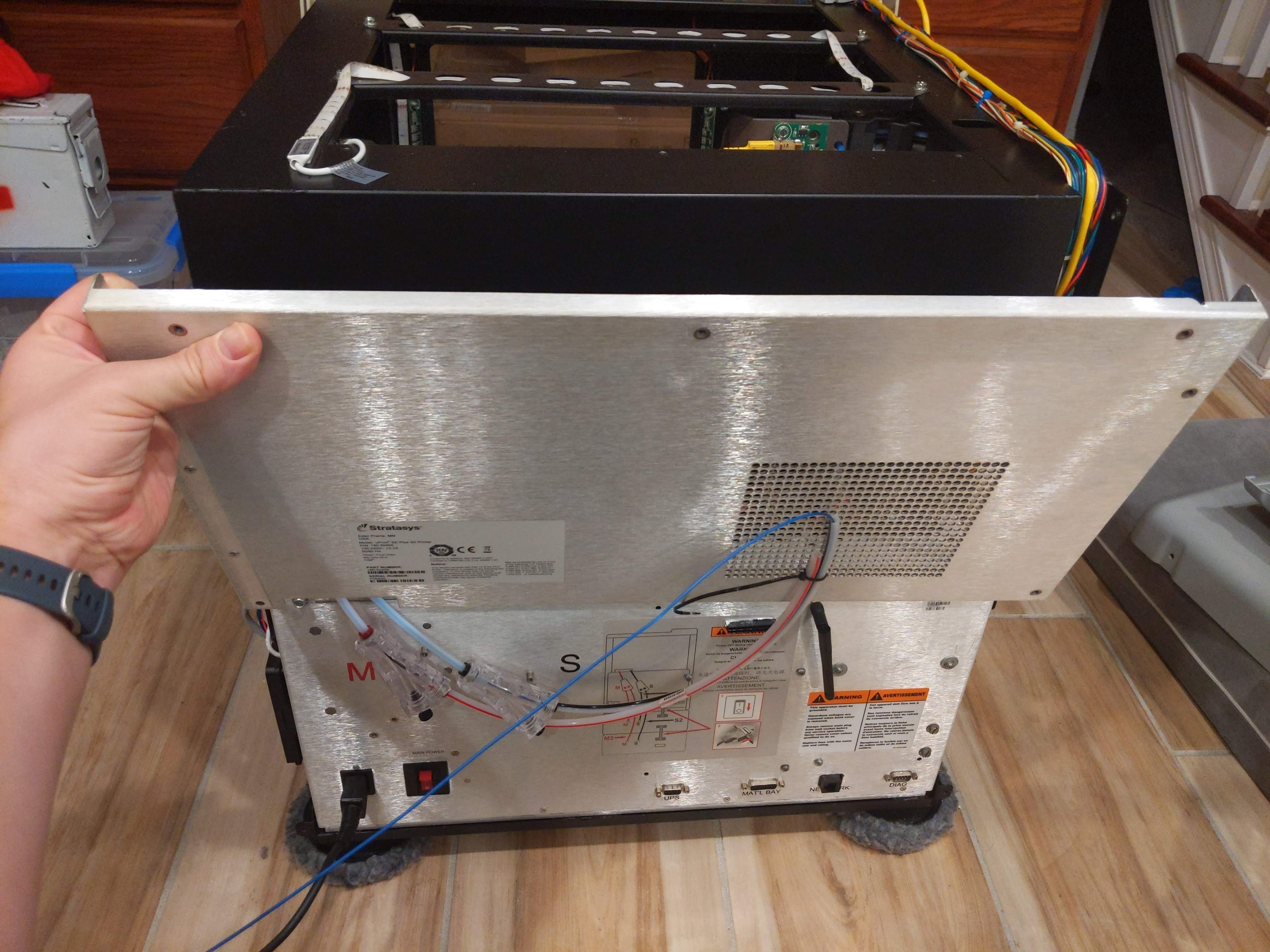
Remove the top panel by unscrewing the screws on the back of the 3D printer.
Carefully pull toward the back of the 3D printer to remove the top panel.
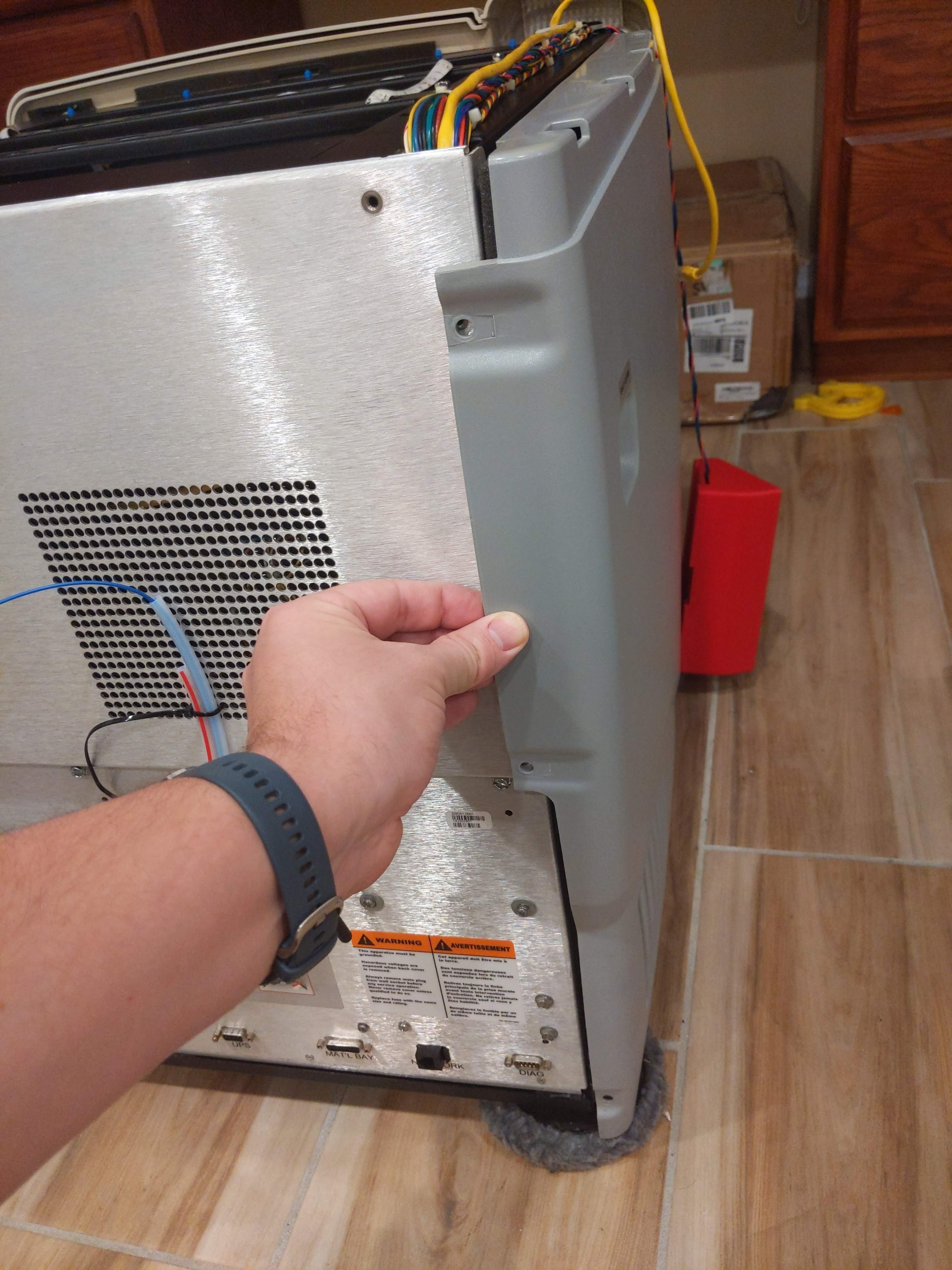
Remove the screws on the side panels.
Carefully pull toward the back of the 3D printer to remove the side panels.
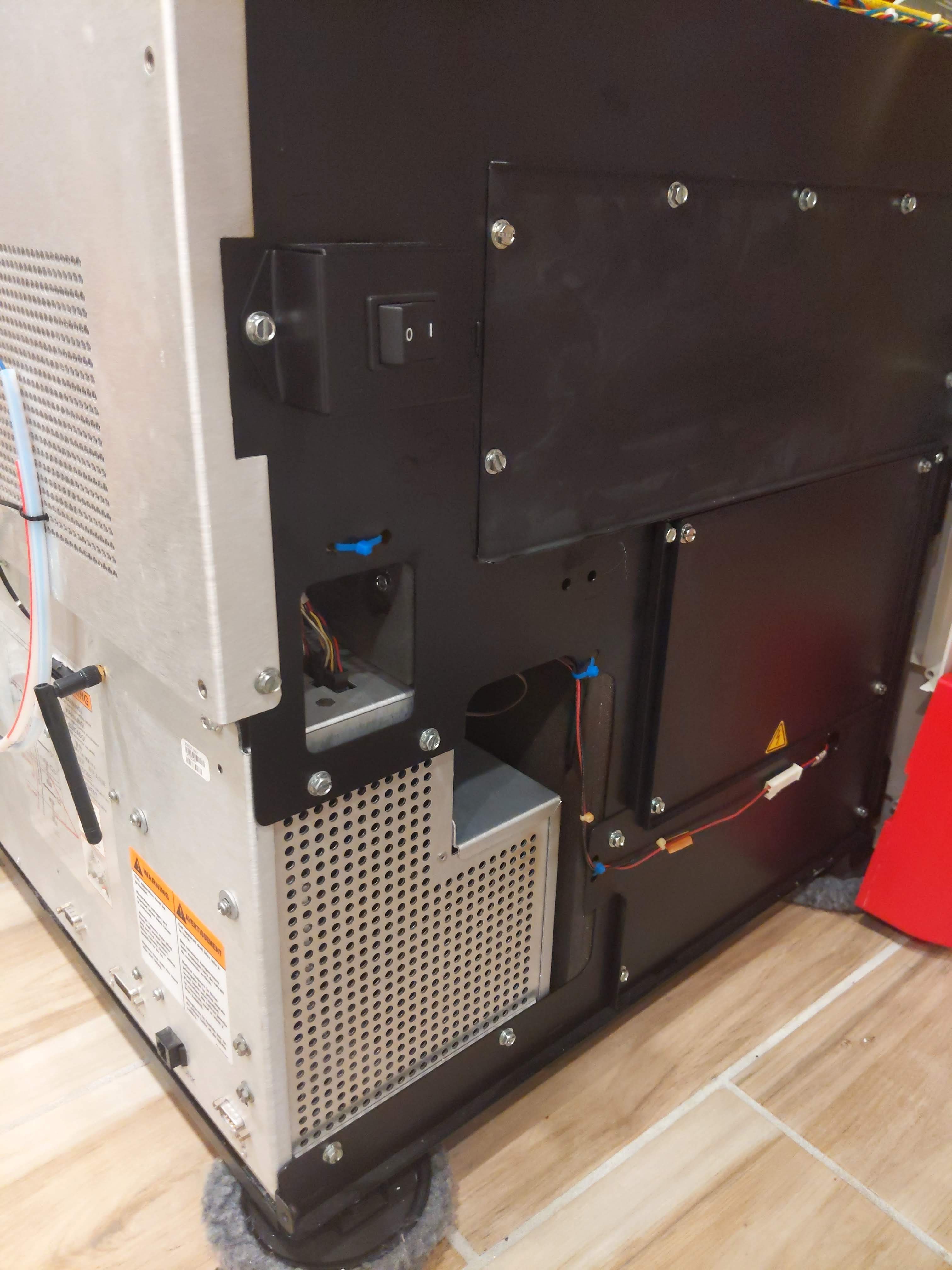
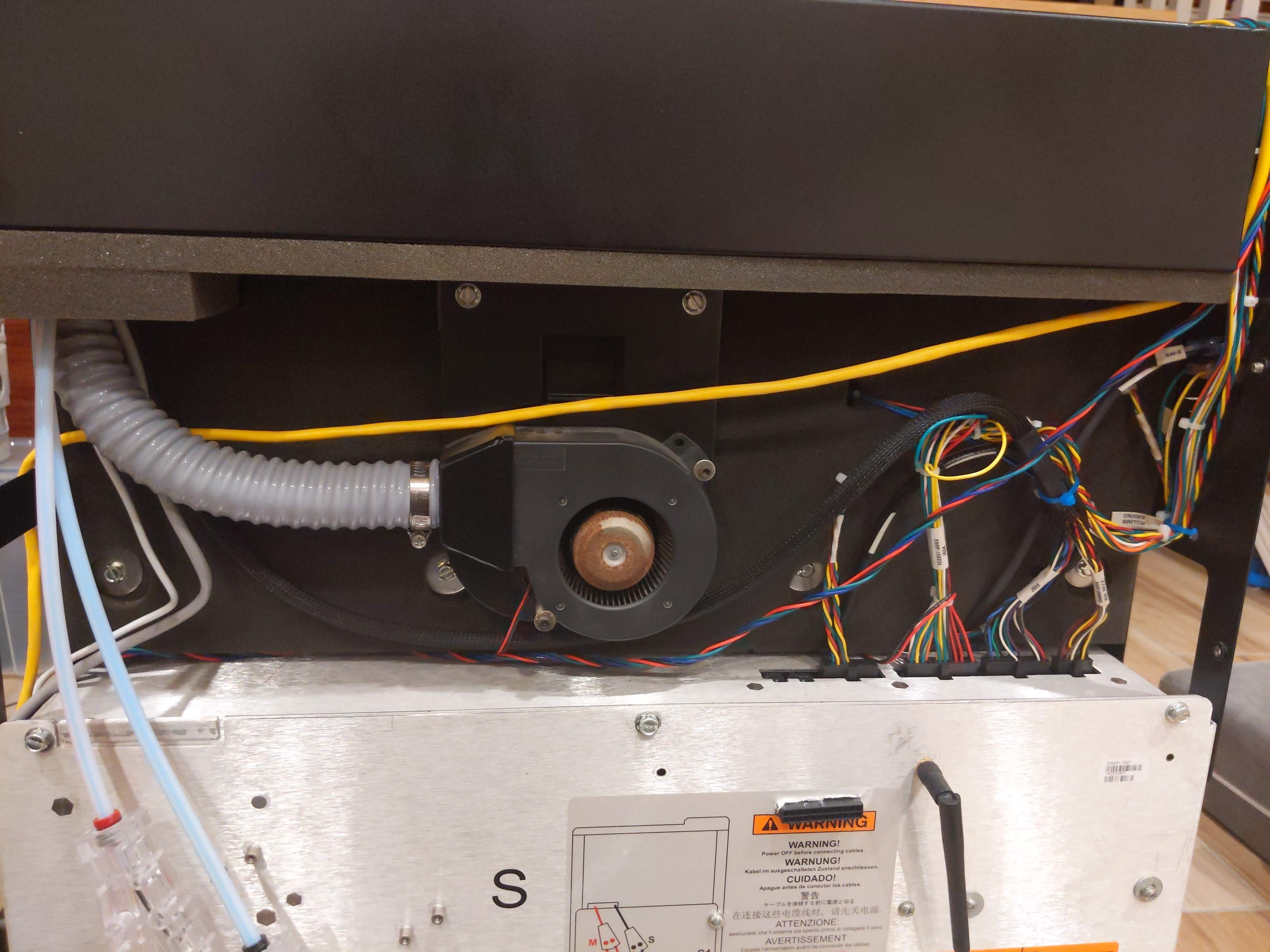
Remove the screws on the top back metal panel to expose the head blower fan.
Carefully remove the top back metal panel.
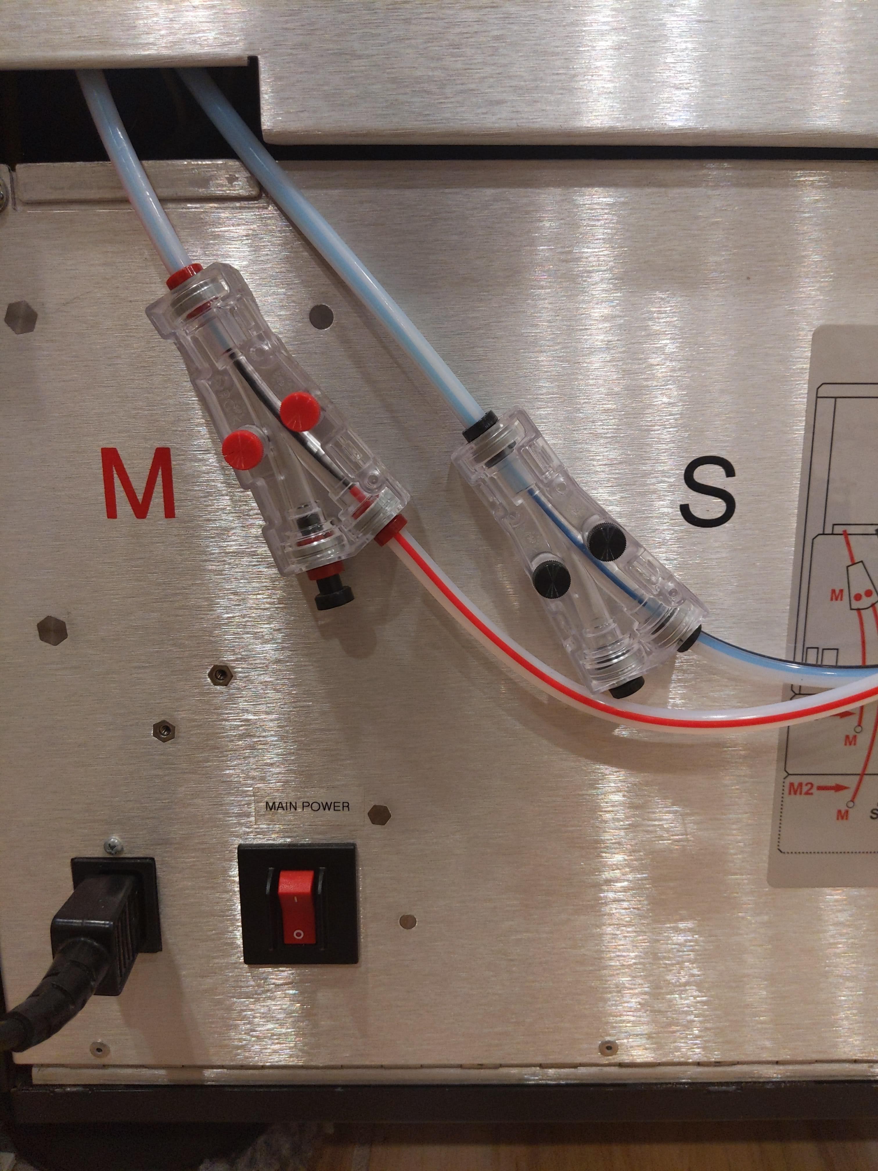
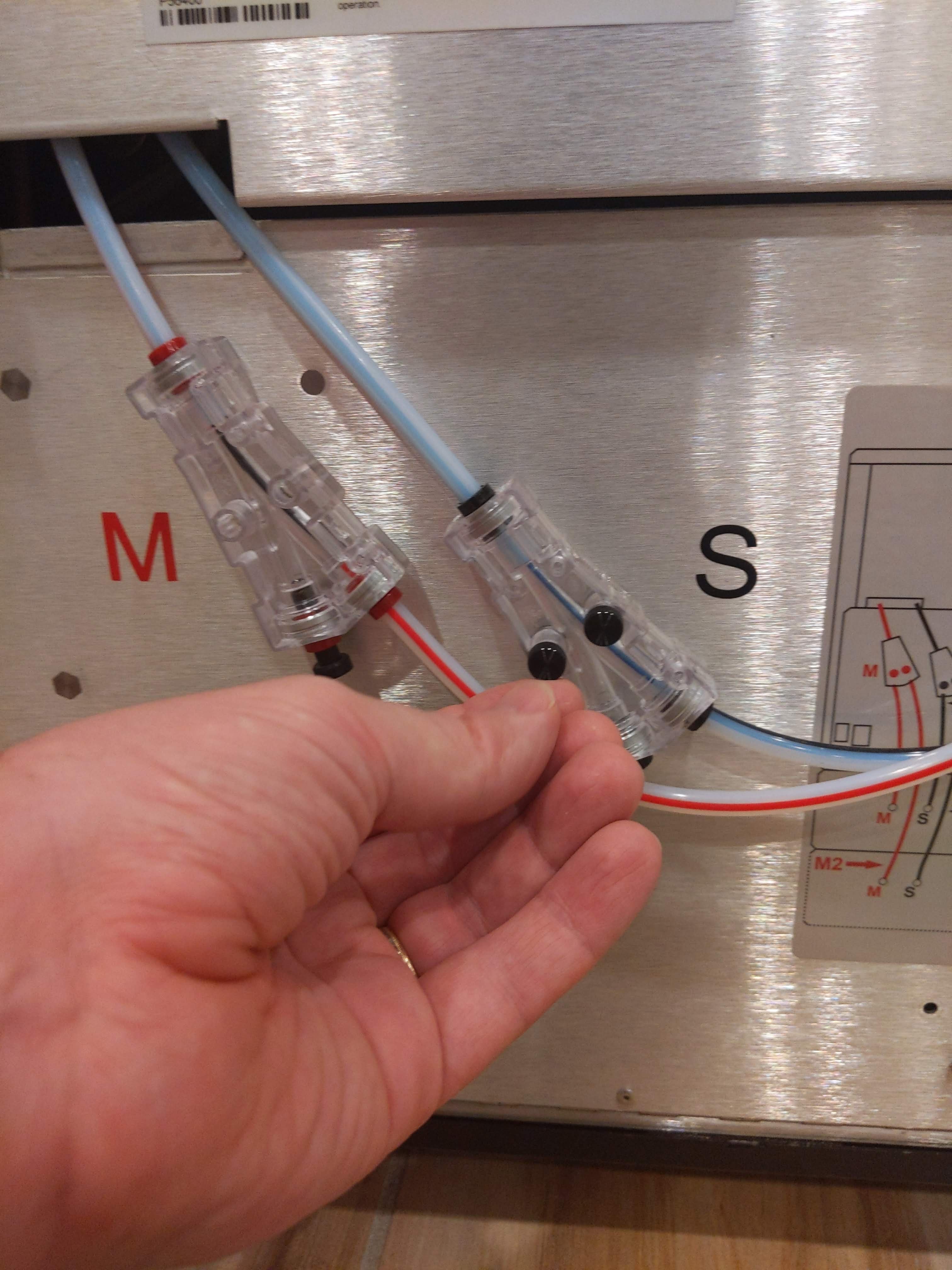
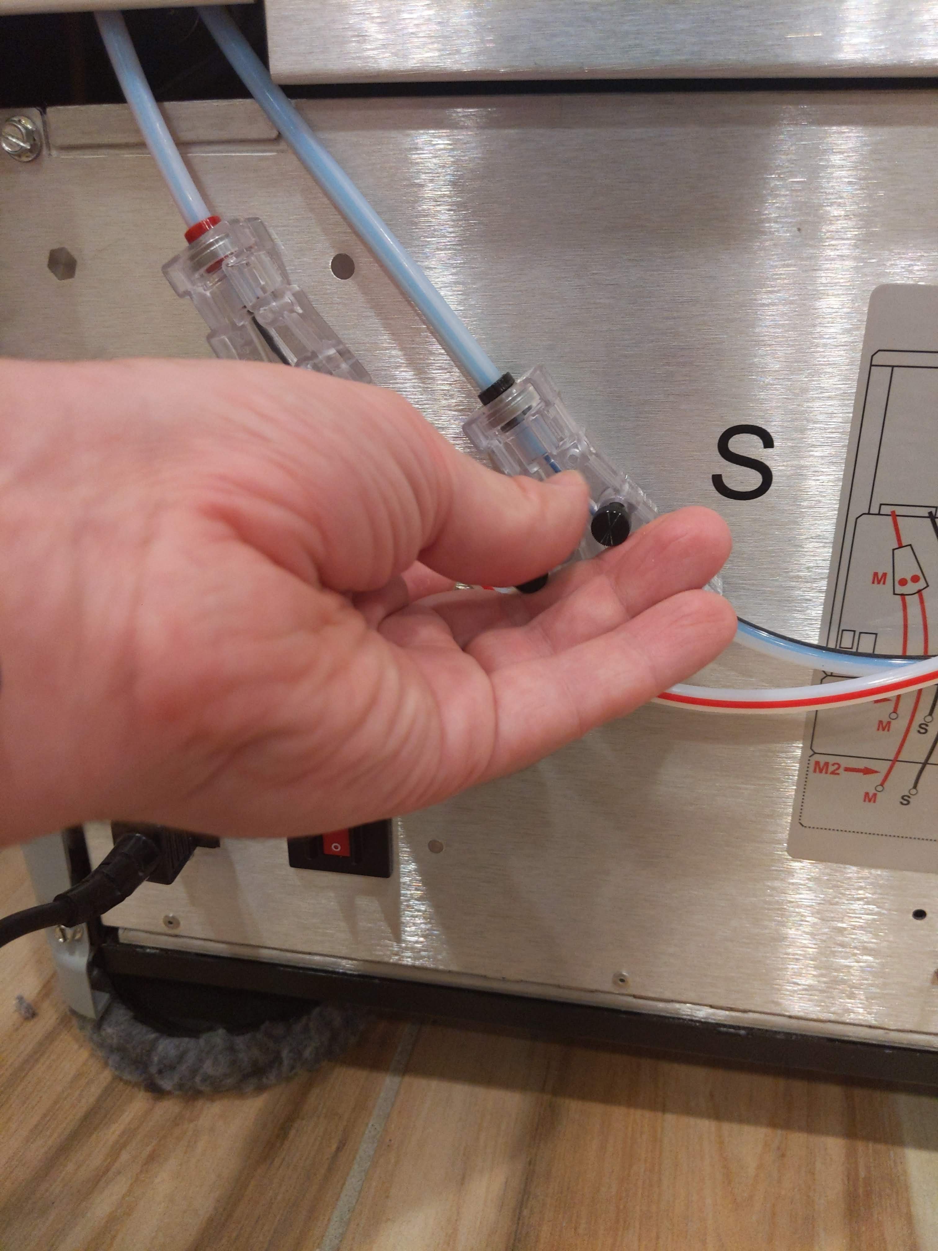
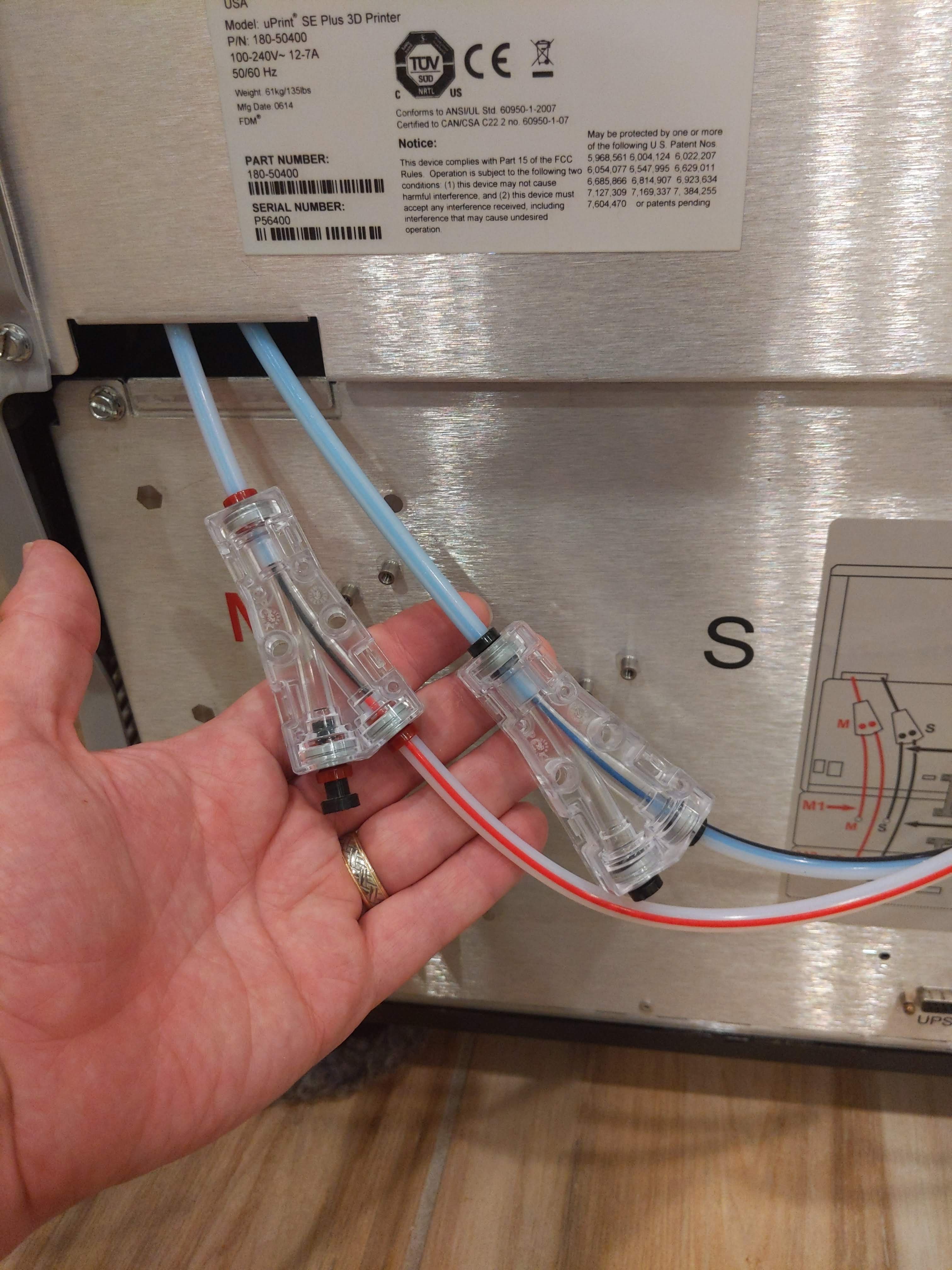
Disconnect the filament guide tubes from the Y-adapter on the back of the 3D printer.
Break the filament if necessary.
Unscrew the filament Y-adapters.
2
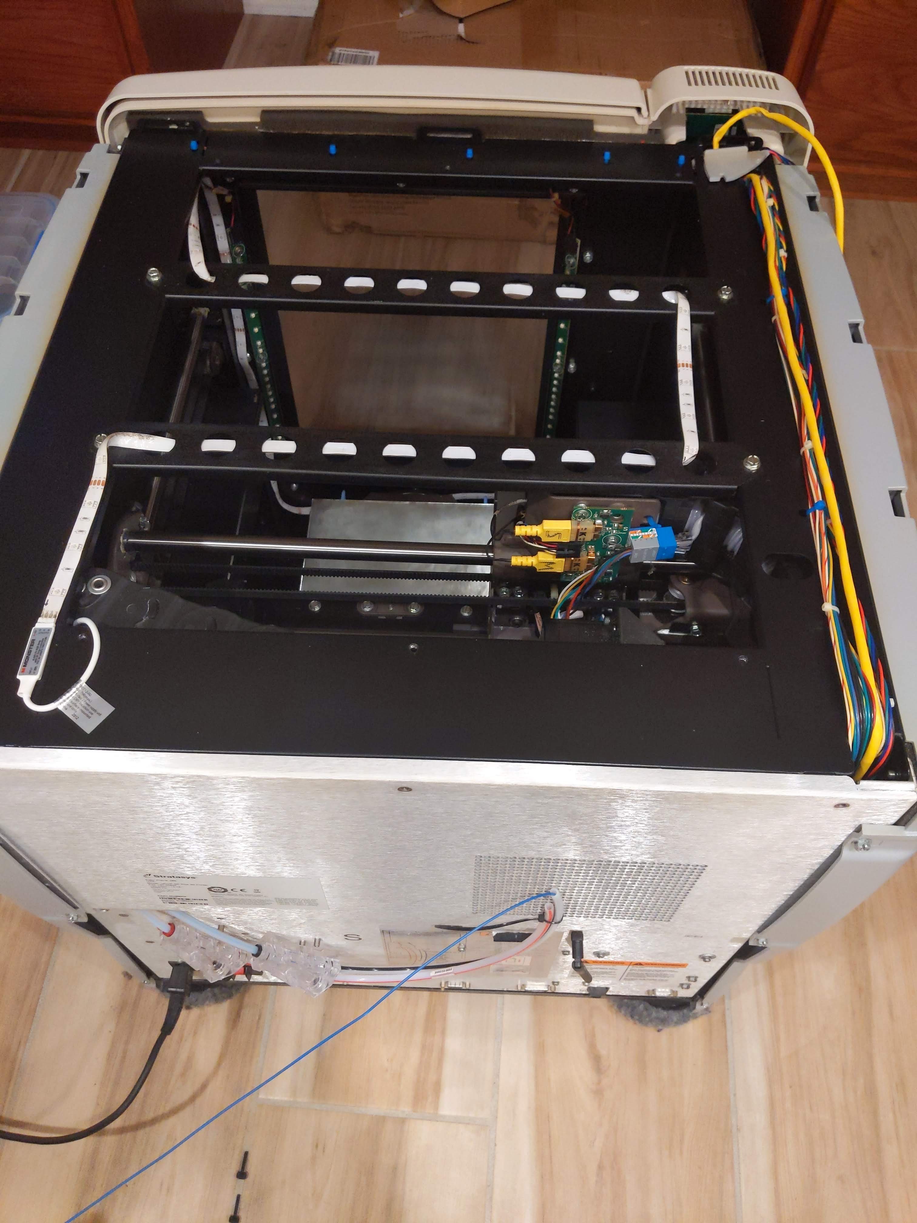
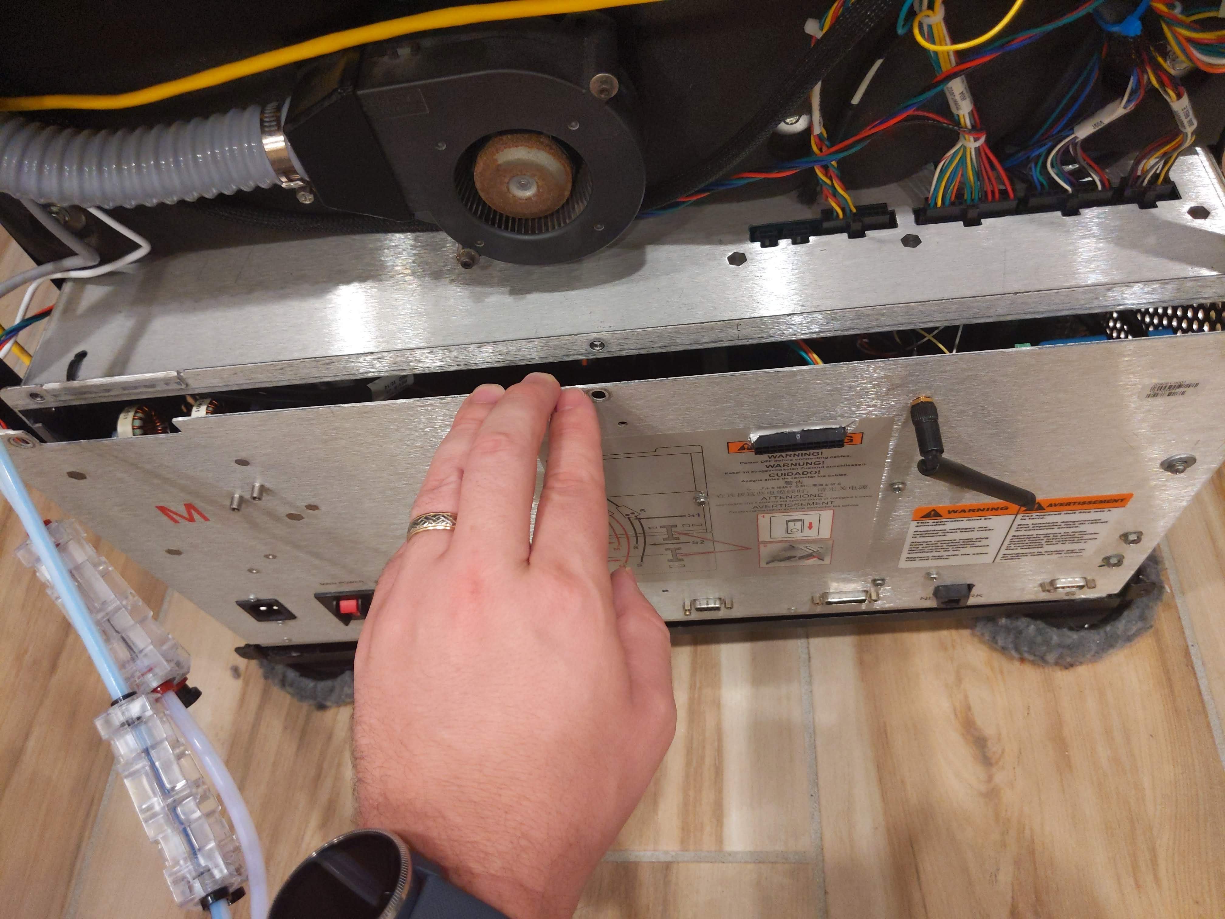
Remove the Electronics Cabinet from the back of the 3D printer.
Unscrew the electronics cabinet from the frame of the 3D printer housing.
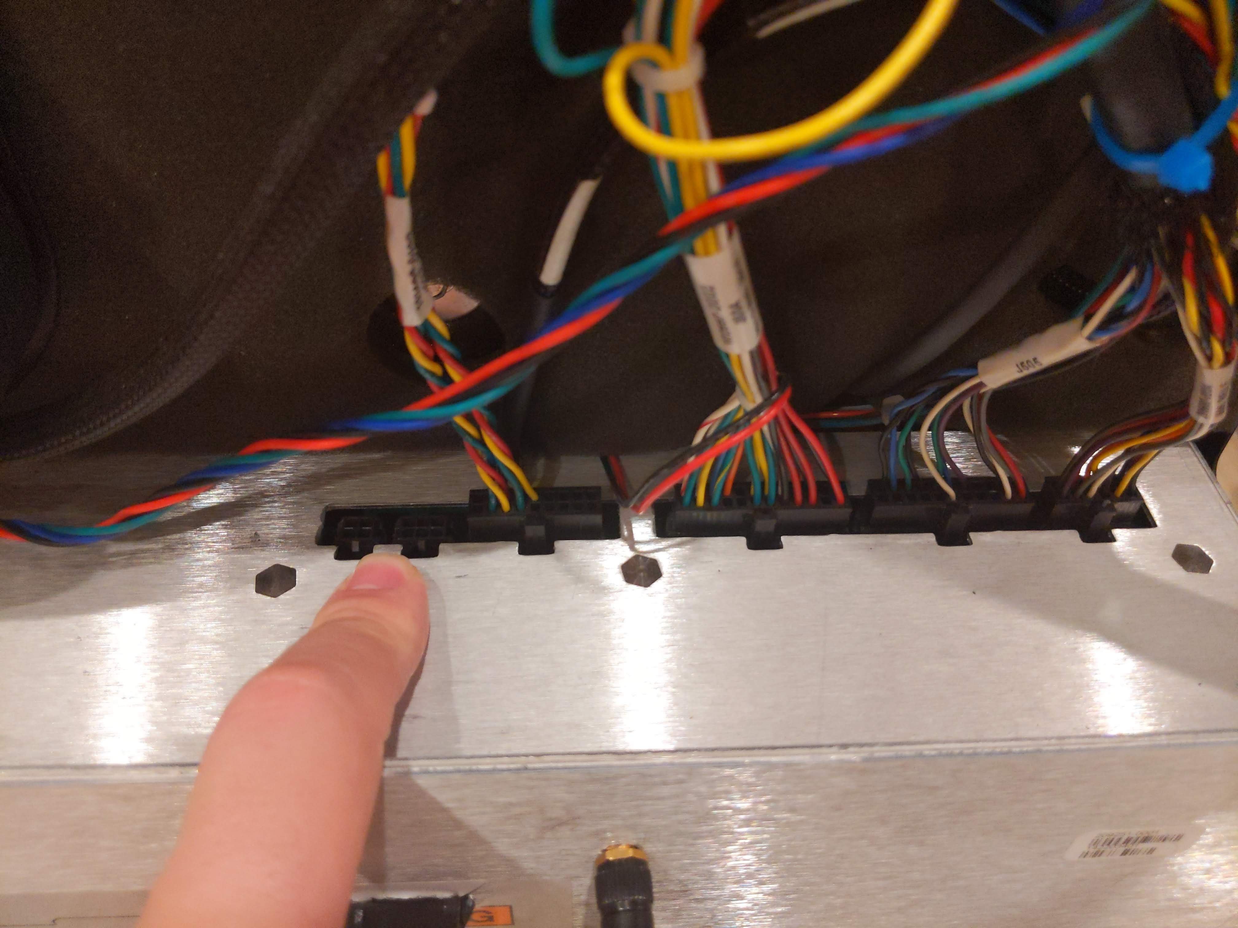
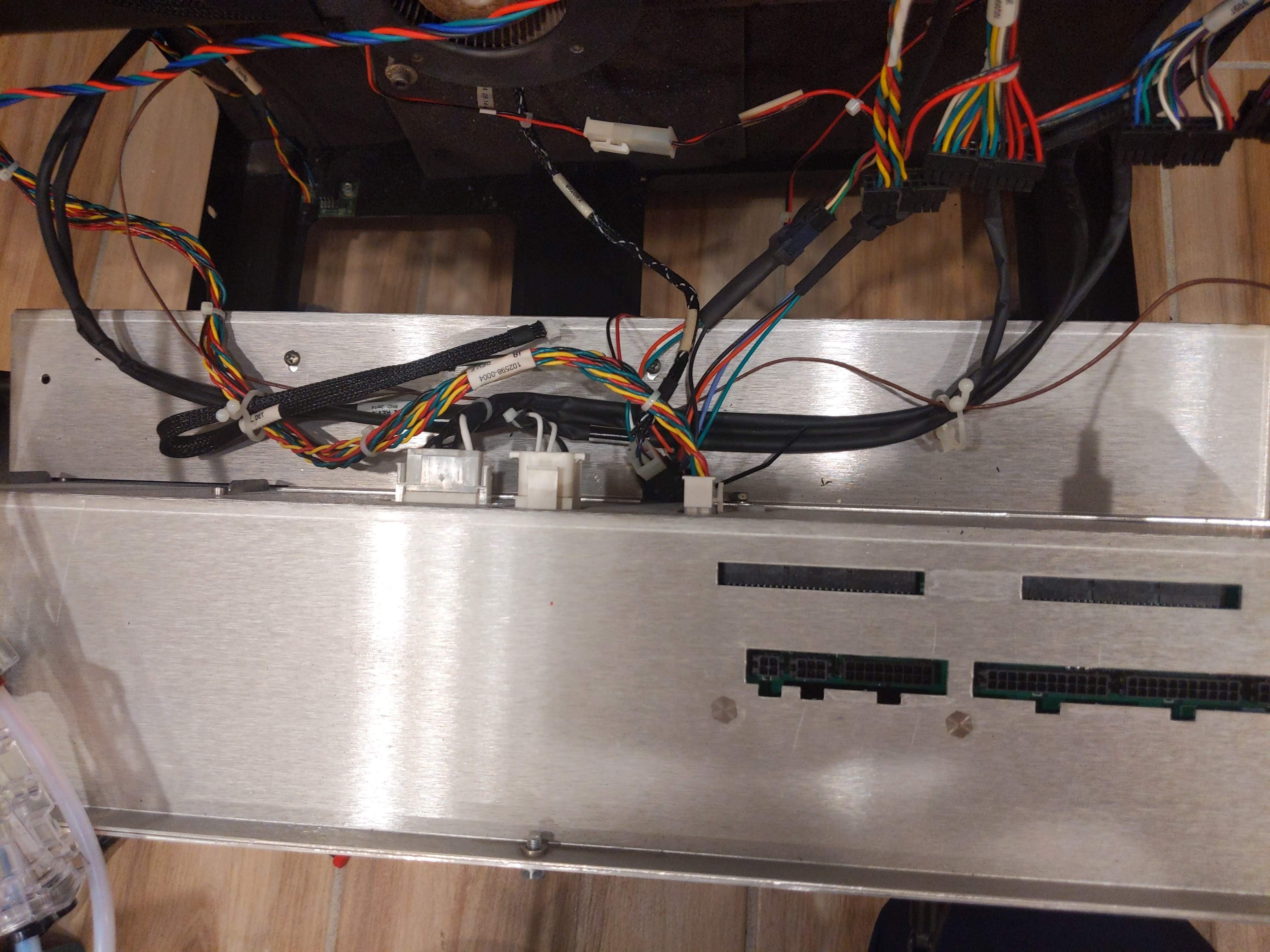
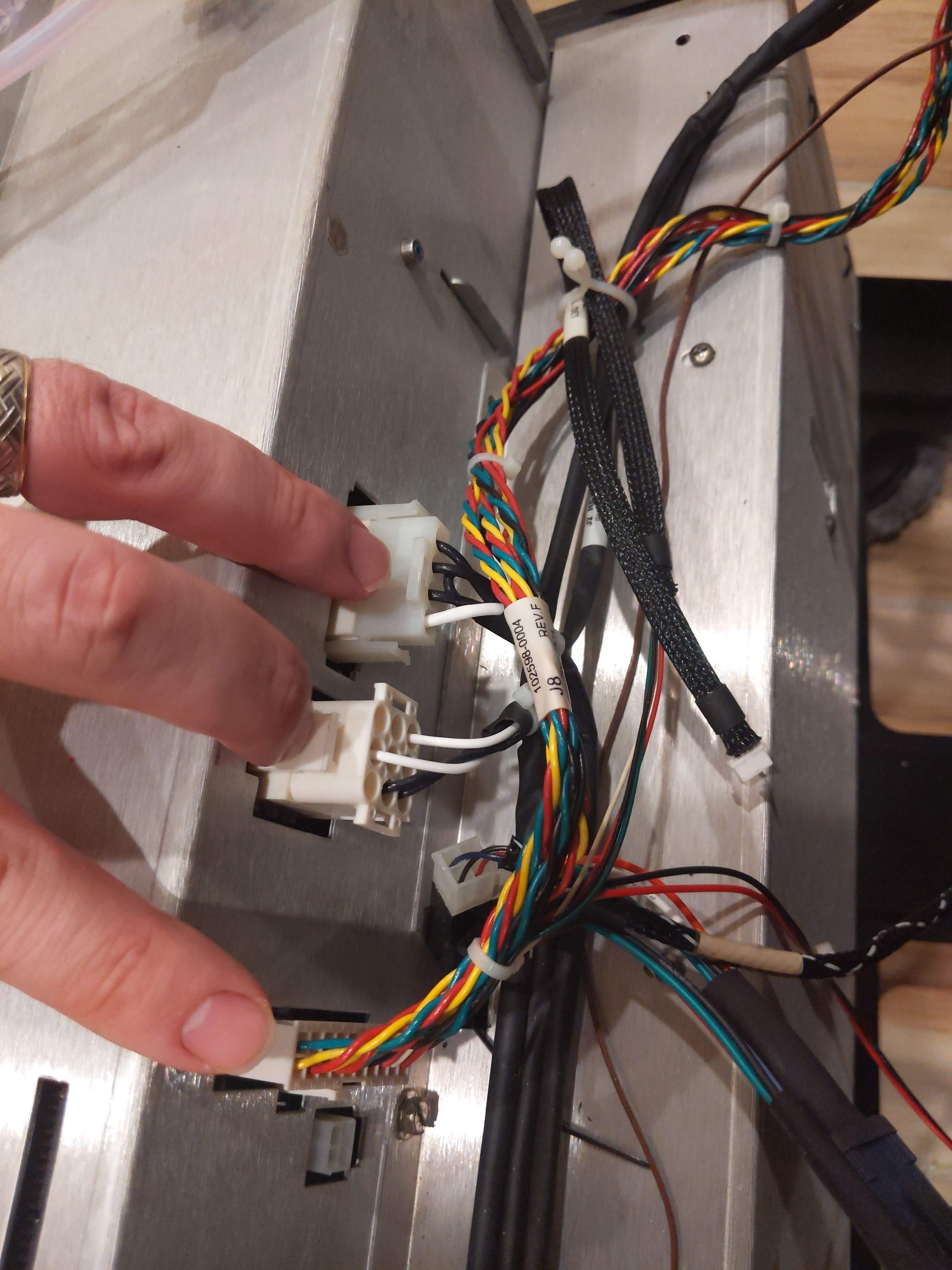
Disconnect wires from the top of the electronics cabinet.
Reach through the side to the middle of the 3D printer to disconnect the chamber thermal couple, Z-axis motor wires, and power input wires from the back of the electronics cabinet. If needed carefully pull the electronics cabinet part way out of the back of the 3D printer to get better access to the wires.
Double check to ensure all wires are disconnected from the electronics cabinet.
Carefully pull to remove the electronics cabinet from the back of the 3D printer.
3
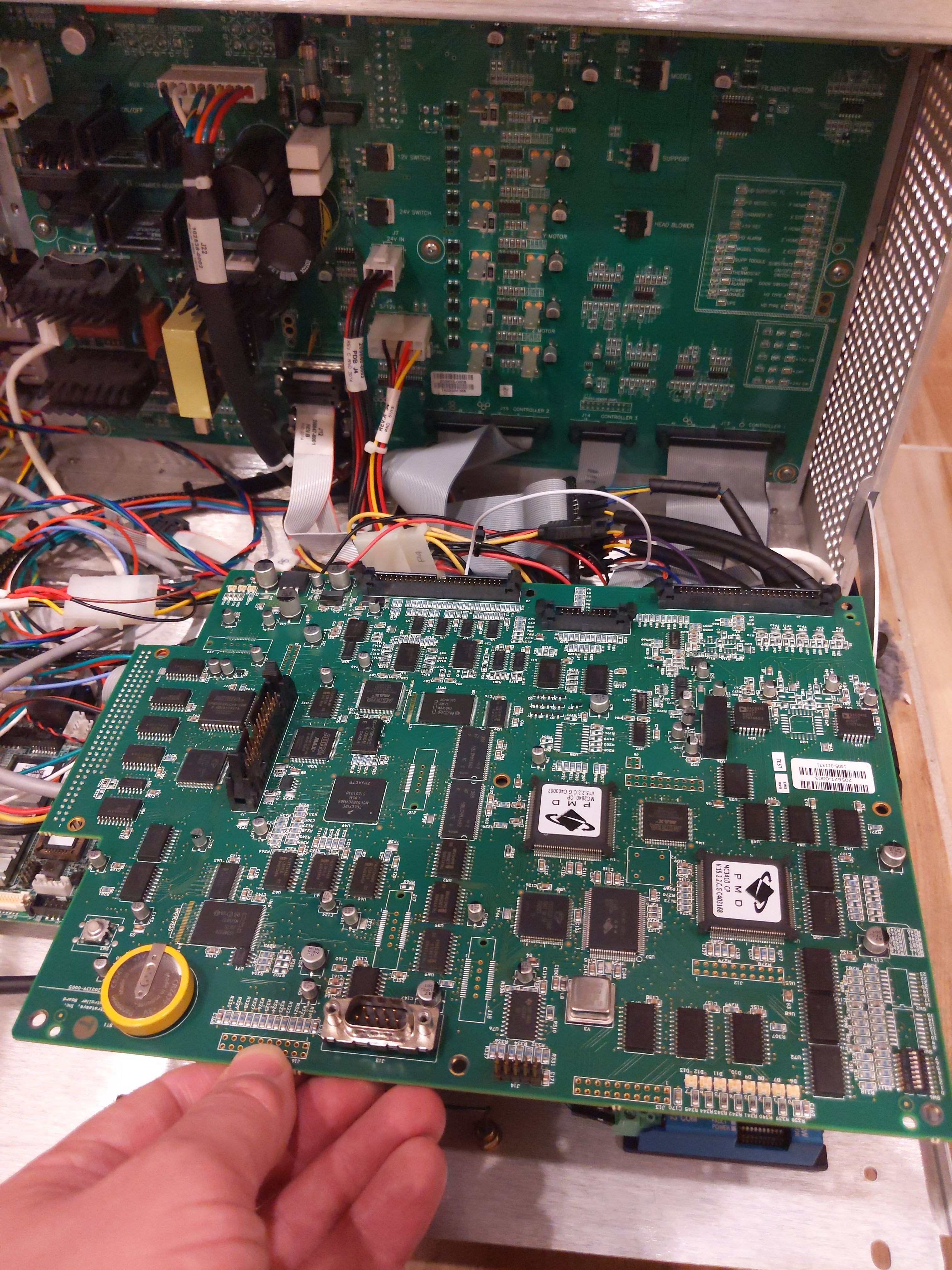
Remove the Stratasys control board from the electronics cabinet.
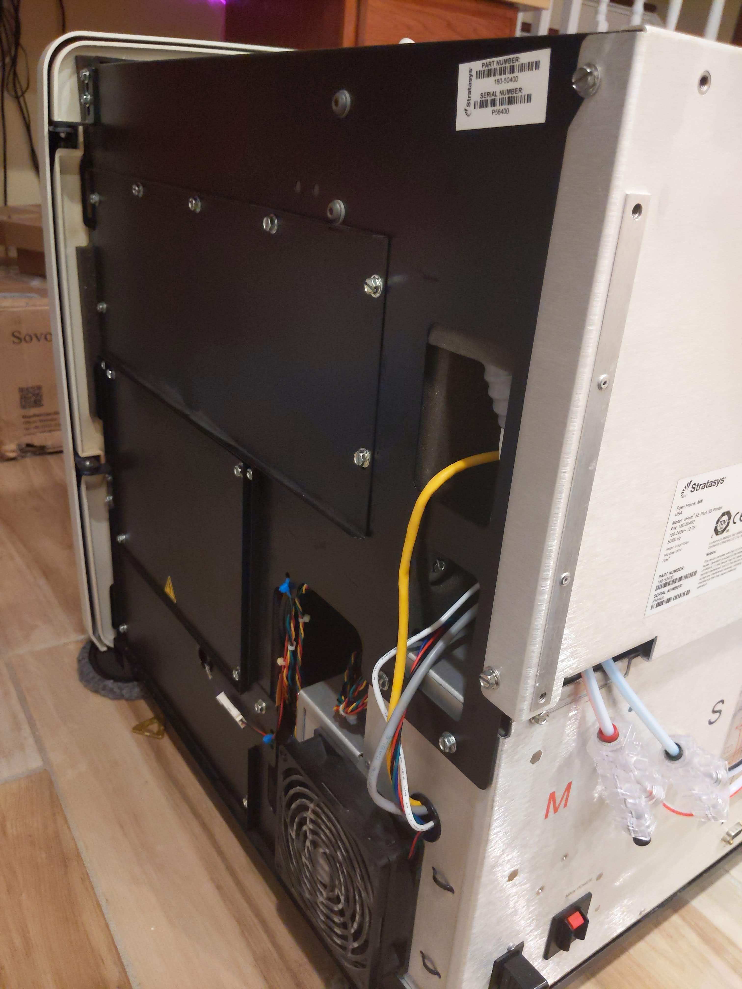
Remove the screws on the back panel.
Carefully open the back panel pulling from the top. This exposes the electronics cabinet of the 3D printer.
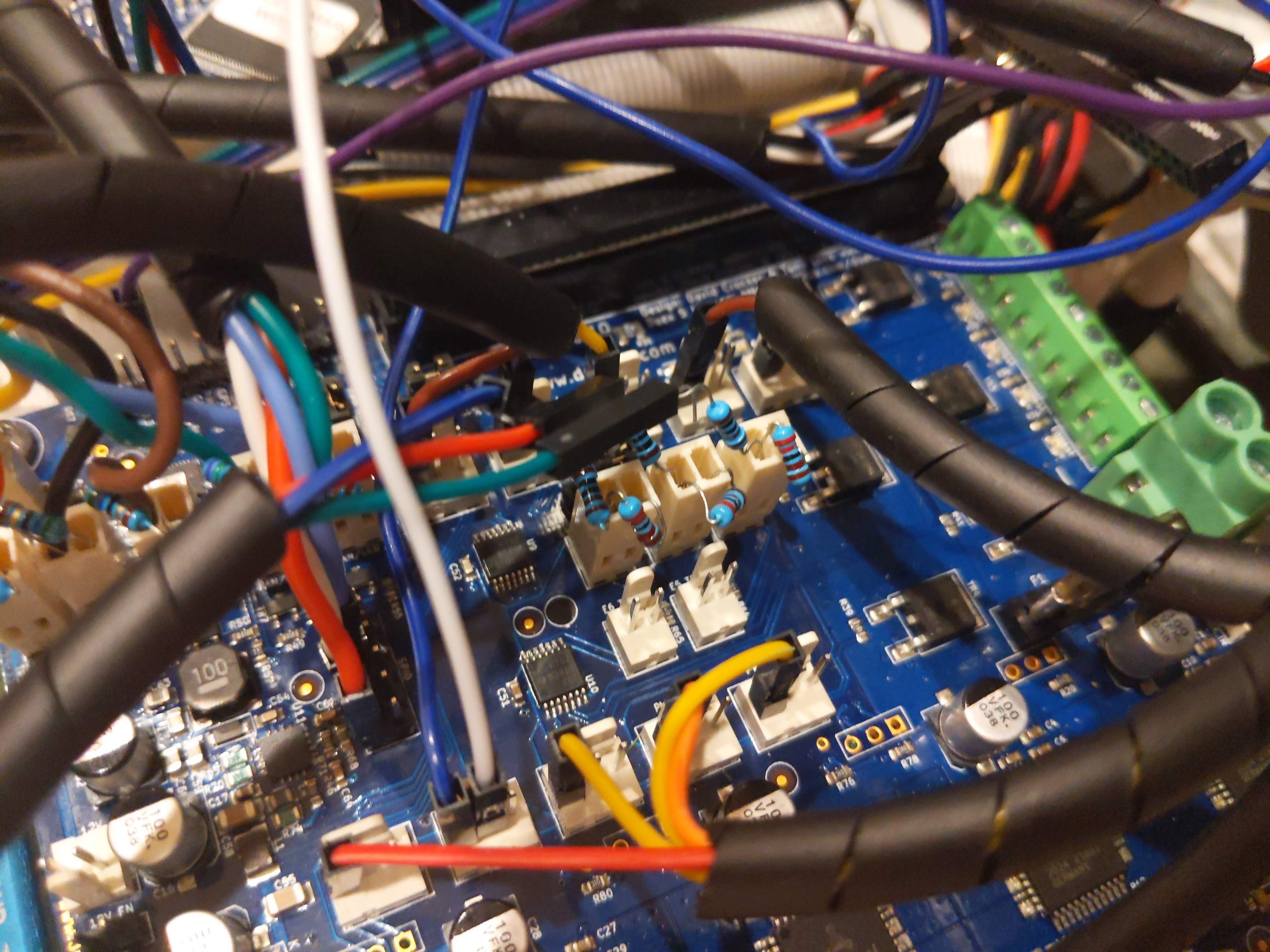
Disconnect the 3 ribbon cables from the control board that connect the control board from the power distribution board (PDB).
Unscrew the control board at the 6 standoff locations.
Remove the standoffs.
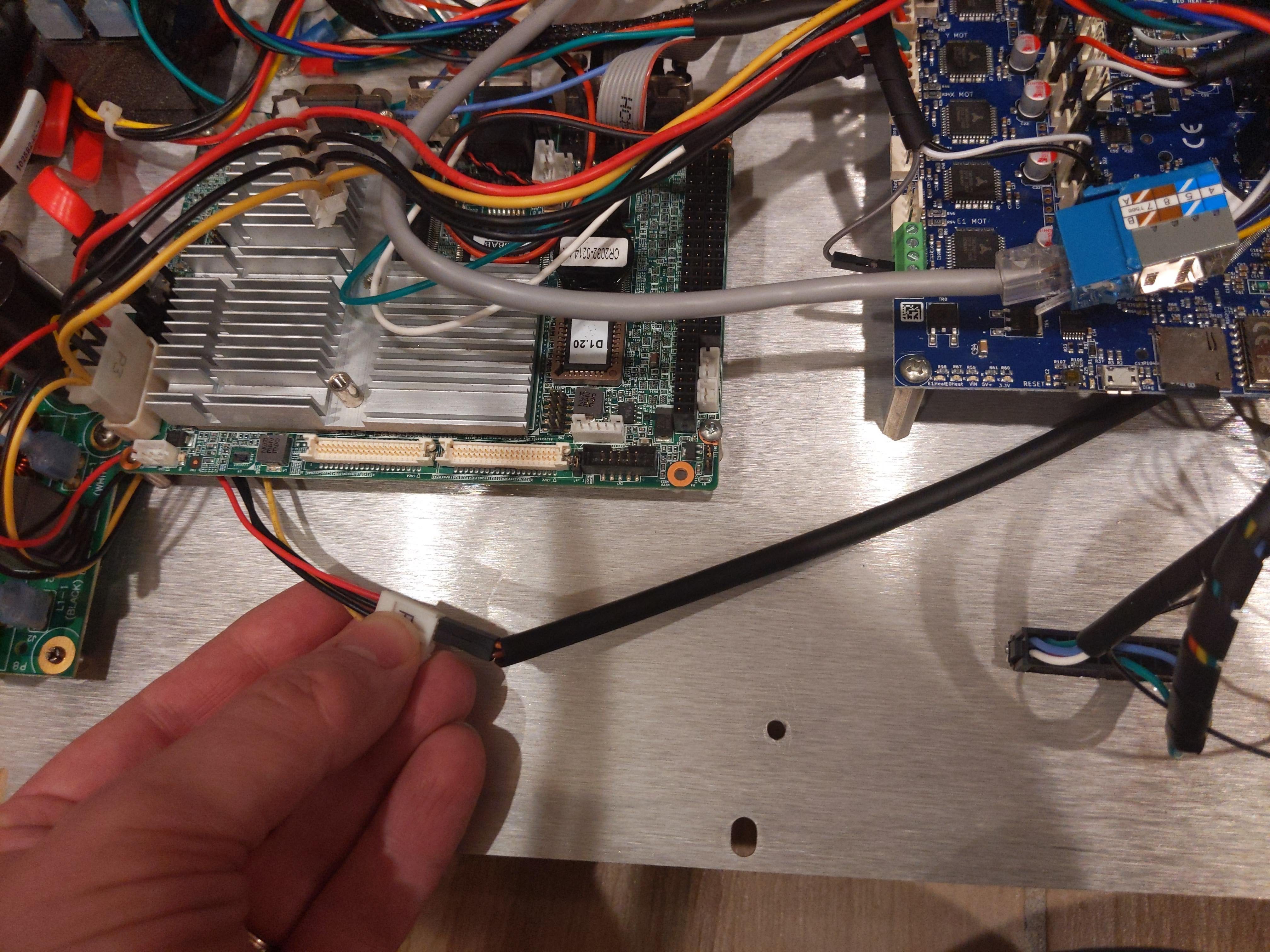
Disconnect the control board from the single board computer (SBC).
4
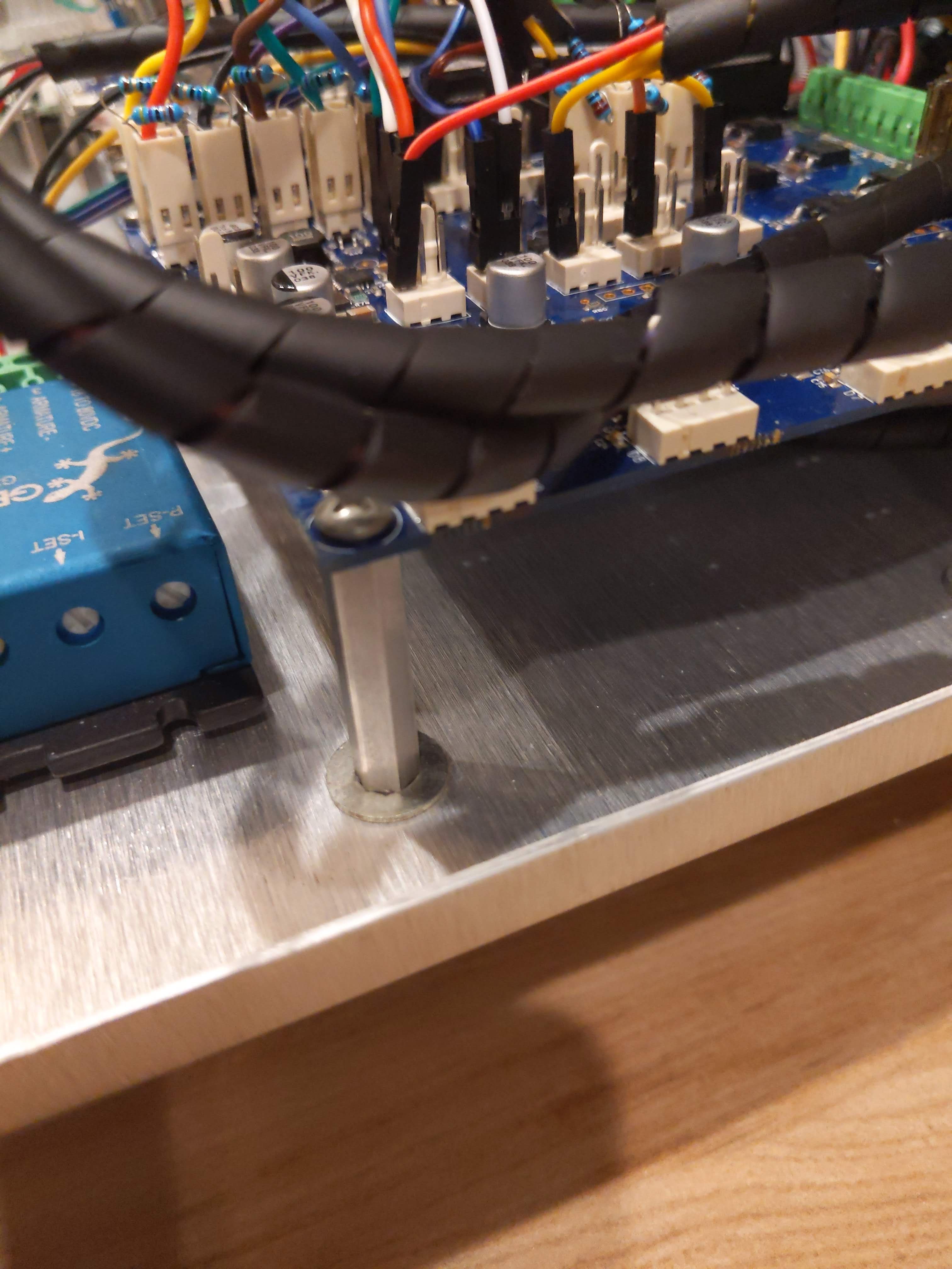
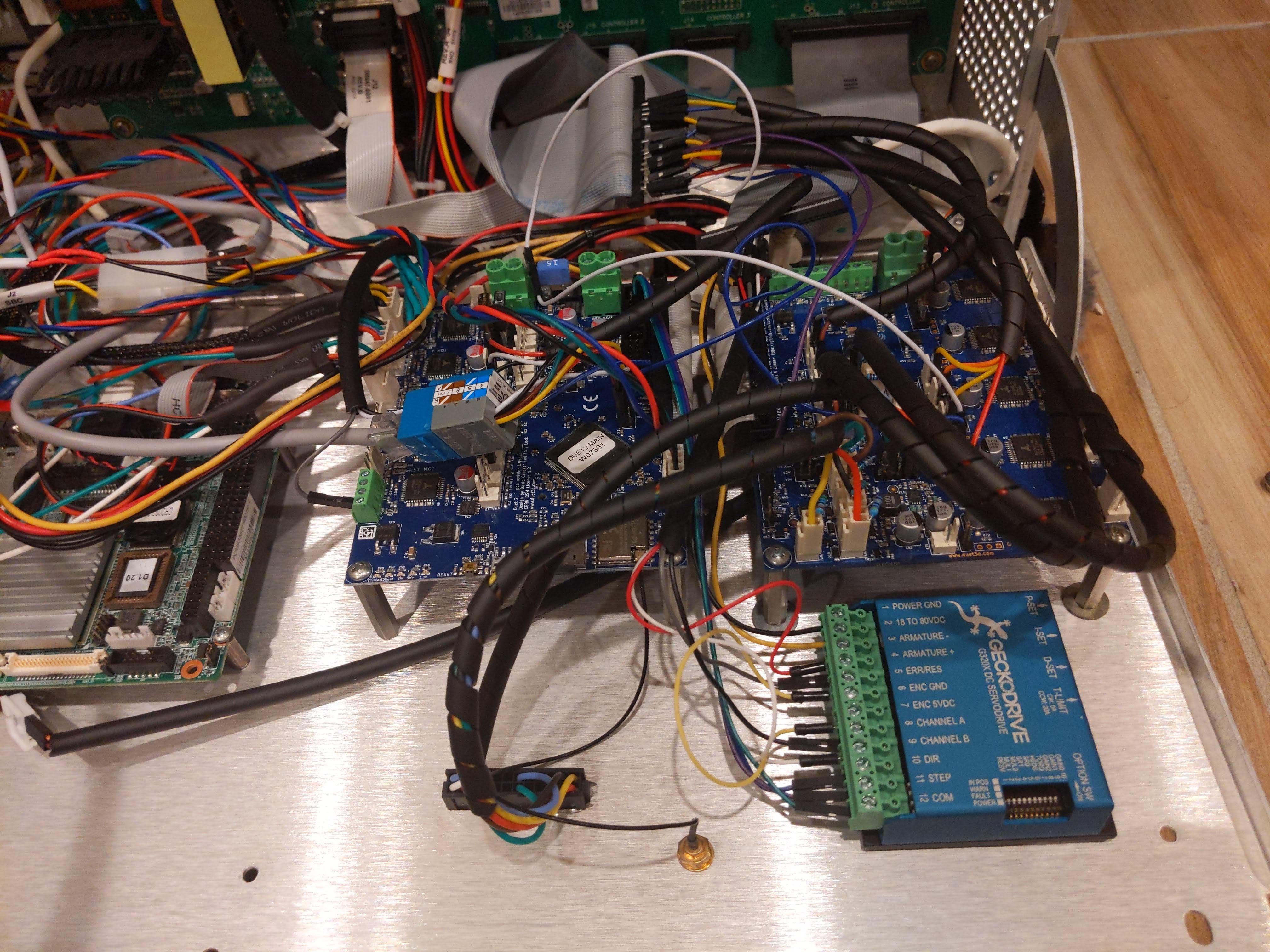
Install the Duet 2 Wifi and Duex5 expansion boards and the Geckodrive G320X DC servo motor driver on the inside back panel of the 3D printer.
Connect the Duet 2 WIFI and the Duex5 board using the ribbon cable included with the purchase of the Duex5 expansion board.
Locate the mounting location of the Duet 2 WIFI and Duex5 boards leaving about a 1" spacing between the boards. Mount the Duet 2 WIFI board on the side nearest the SBC.
Drill holes in the back panel at the appropriate places utilizing the existing holes from the control board mounting when possible.
Reattach the standoffs.
Mount the Duet 2 WIFI and Duex5 boards on top of the standoffs.
Using double stick foam tape attach the Geckodrive G320X just above the Duet boards. (Further from the bottom of the 3D printer)
5
Connect the Duet 2 WIFI and Duex5 expansion boards to the Power Distribution Board.
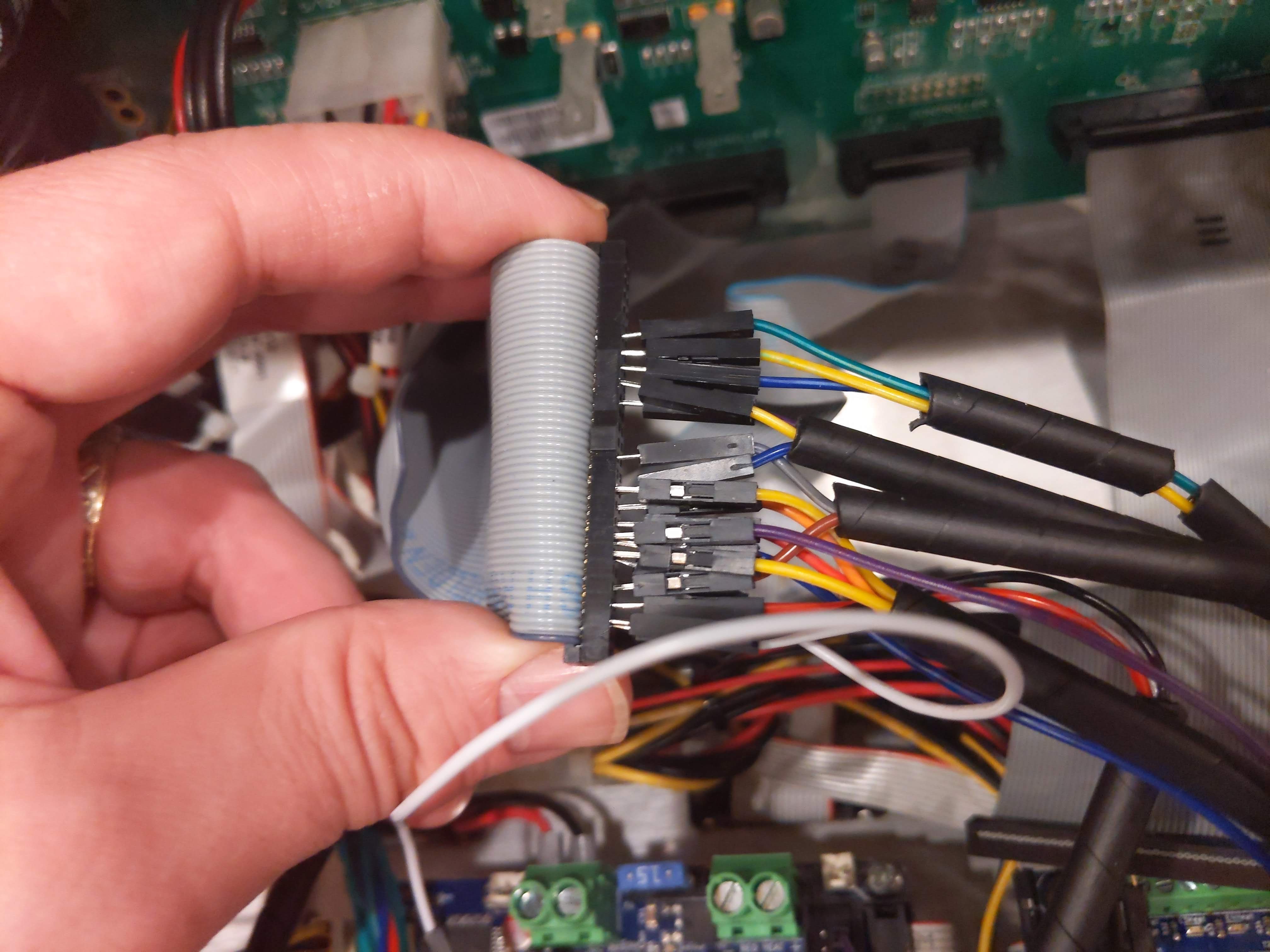
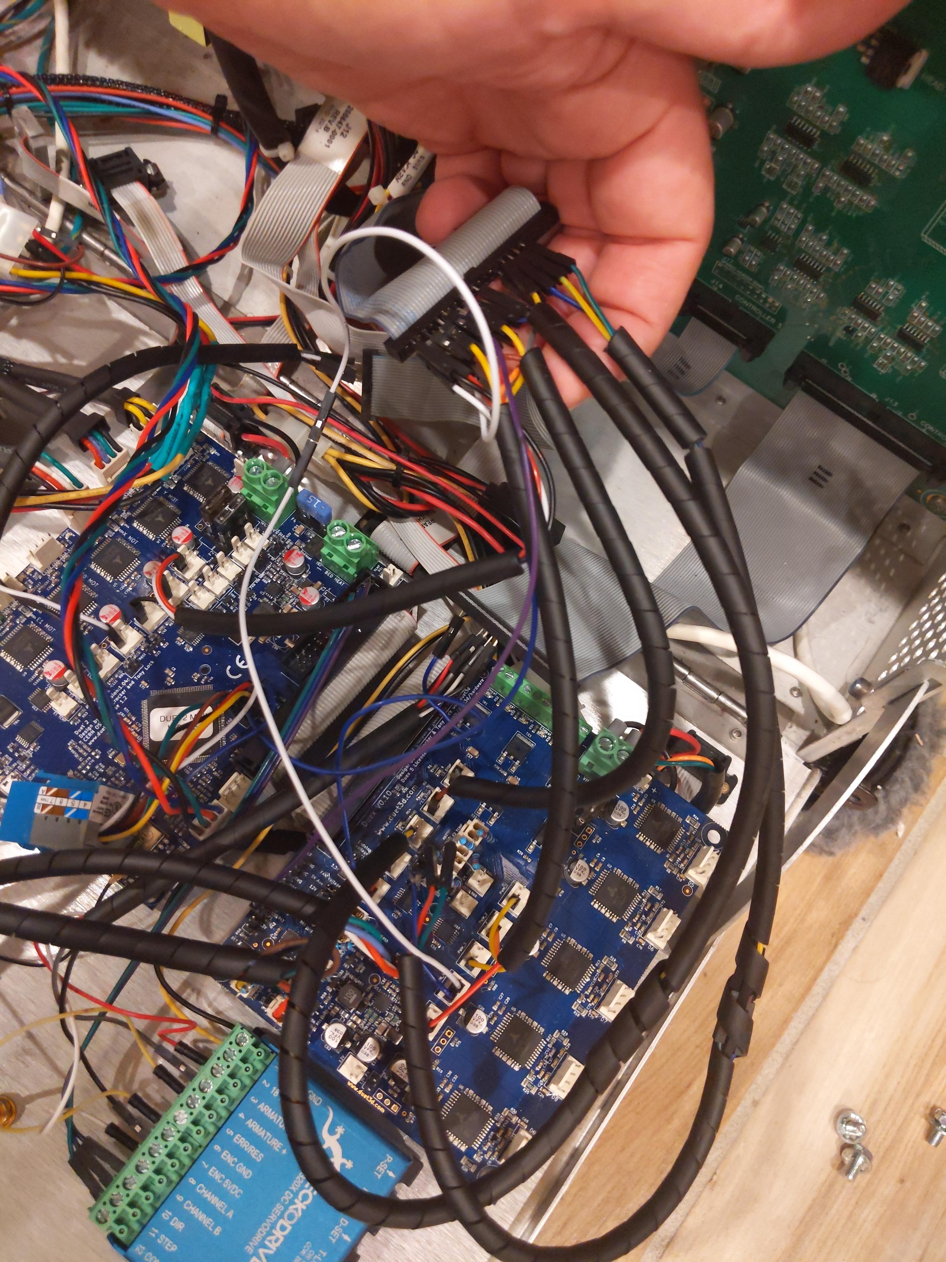
Using the 16" long Dupont (Male to Female) wires connect the Duet 2 WIFI and the Duex5 boards to the ribbon cables J13, J14, J15 coming out of the PDB following the wiring diagram. Do NOT connect the wires to the Geckodrive G320X board yet.
Insert the Male (pointy) end into the ribbon cable. Use a multimeter if needed to make sure the correct wires are plugged into the correctly numbered location in the ribbon cable.
Once certain the correct pin is chosen, connect the female (socket) end into the the appropriate locations on the Duet 2 WIFI and Duex5 boards.
For accurate thermocouple measurements cut-off the female end of the Dupont wire, strip and solder/connect it to the 1 kOhm resistor of the voltage divider. Apply heat shrink as needed.
Crimp the Molex connector crimps that came with the Duet 2 WIFI or Duex5 boards to the other end of the 1 kOhm resistor AND one end of the 2 kOhm resistor.
Crimp the Molex connector crimp to the other end of the 2 kOhm resistor.
Insert the Crimps into the Molex connectors with the 2 kOhm resistor on the ground side of the thermistor (2 pin Molex) input.
6
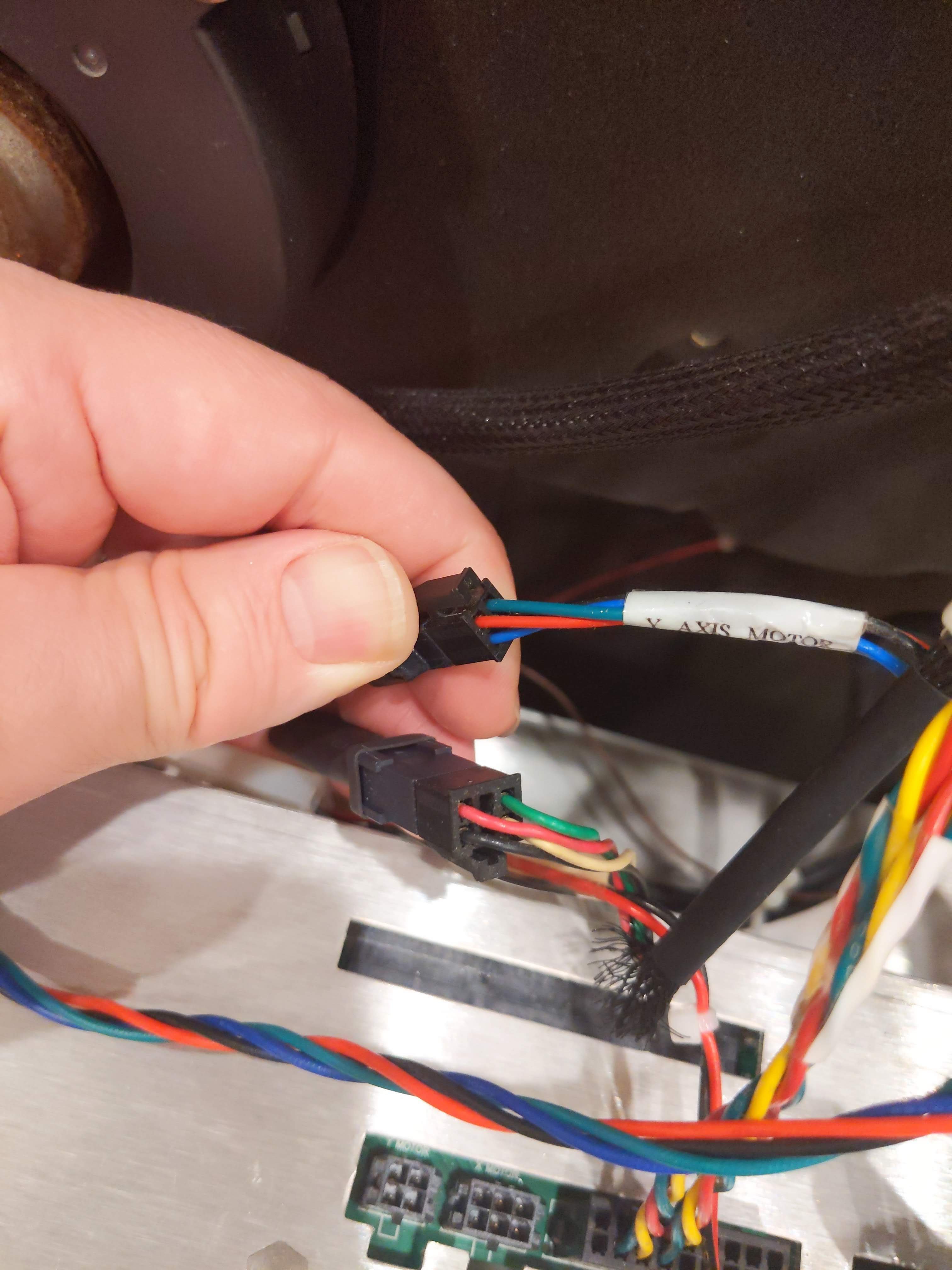
Connect the X-axis, Y-axis, and Z-axis motor leads to the Duet 2 WIFI.
Make a long wiring connector to the X and Y axis inputs that insert into the top of the electronics cabinet.
Test the connector to the X and Y axes to find which pins show continuity to determine the 2 phases of the motors.
Crimp the Microfit 3.0 crimps to the 22 AWG silicone wiring. Insert the crimps into the Microfit 3.0 connectors.
Crimp the Molex crimps to the appropriate wires for each phase and insert the crimps into the Molex connectors.
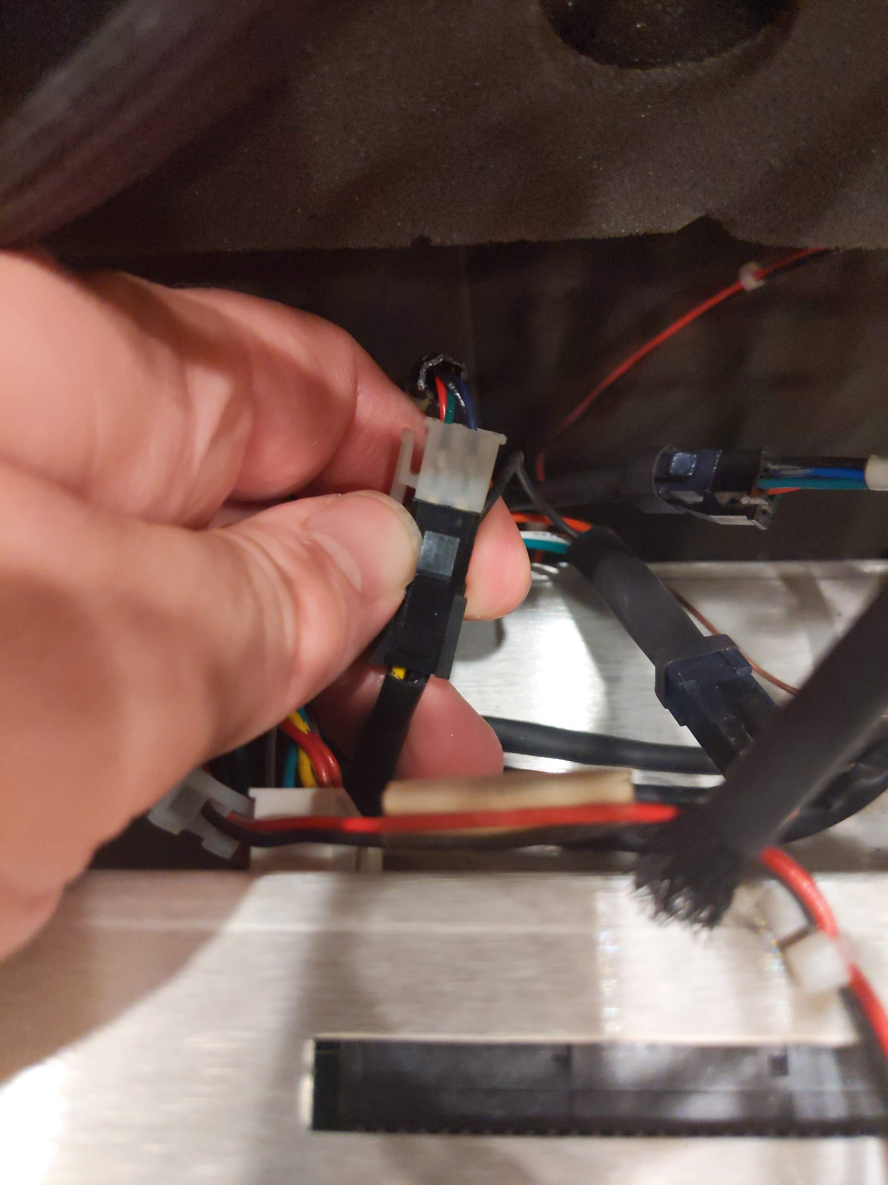
Connect the ATX wire to the Z-axis wires from the back of the electronics cabinet.
Determine which pins connect the 2 phases of the motor as above.
Crimp the Molex crimps to the appropriate wires for each phase and insert the crimps into the Molex connectors.
Feed the wires through the hole on the left hand side of the electronics cabinet and plug the Molex connectors into the Duet 2 WIFI board. Alternatively, cut a small hole in the back of the electronics cabinet and feed the wires under the PDB to connect the X, Y, and Z axes to the Duet 2 WIFI.
Crimp the connectors that came with the duet to the other end of the wire.
Plug in the wires to the Duet 2 WIFI.
7
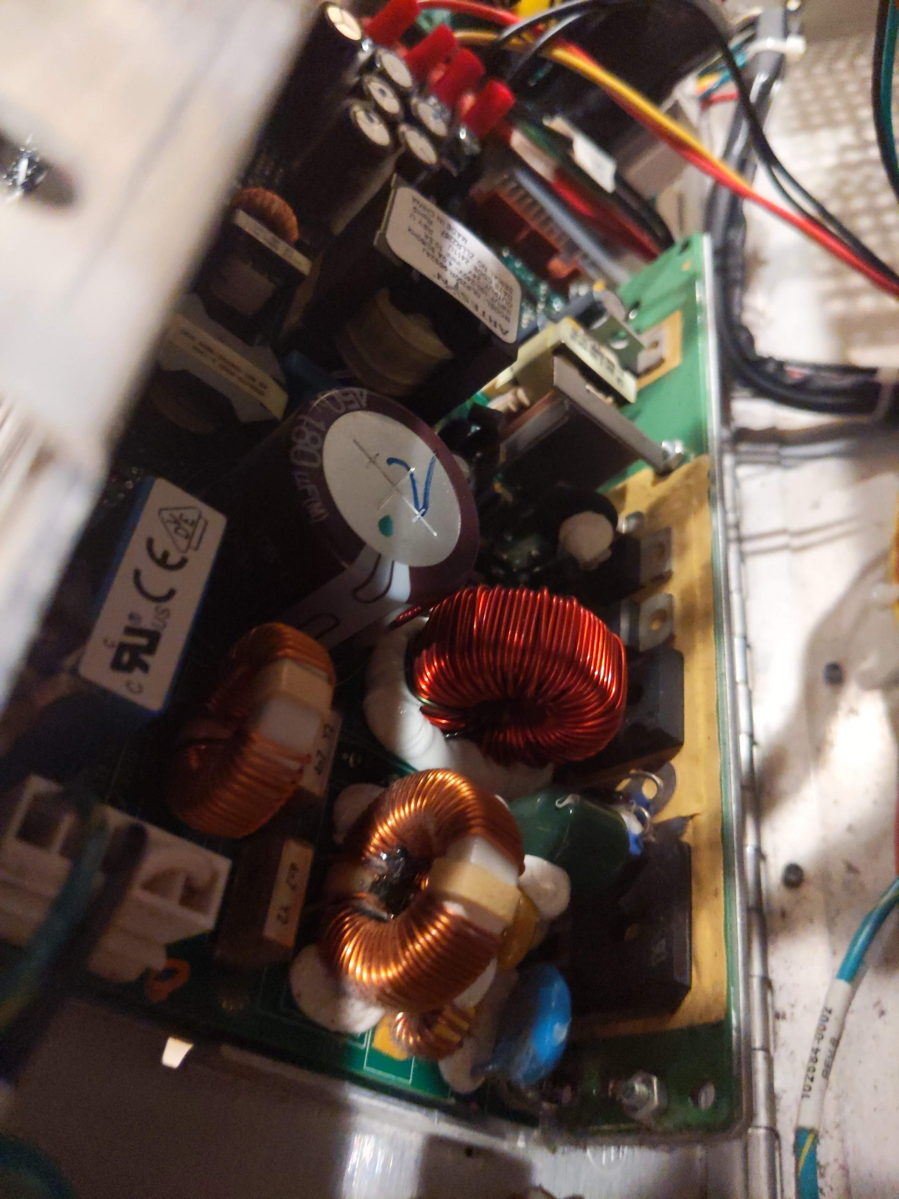
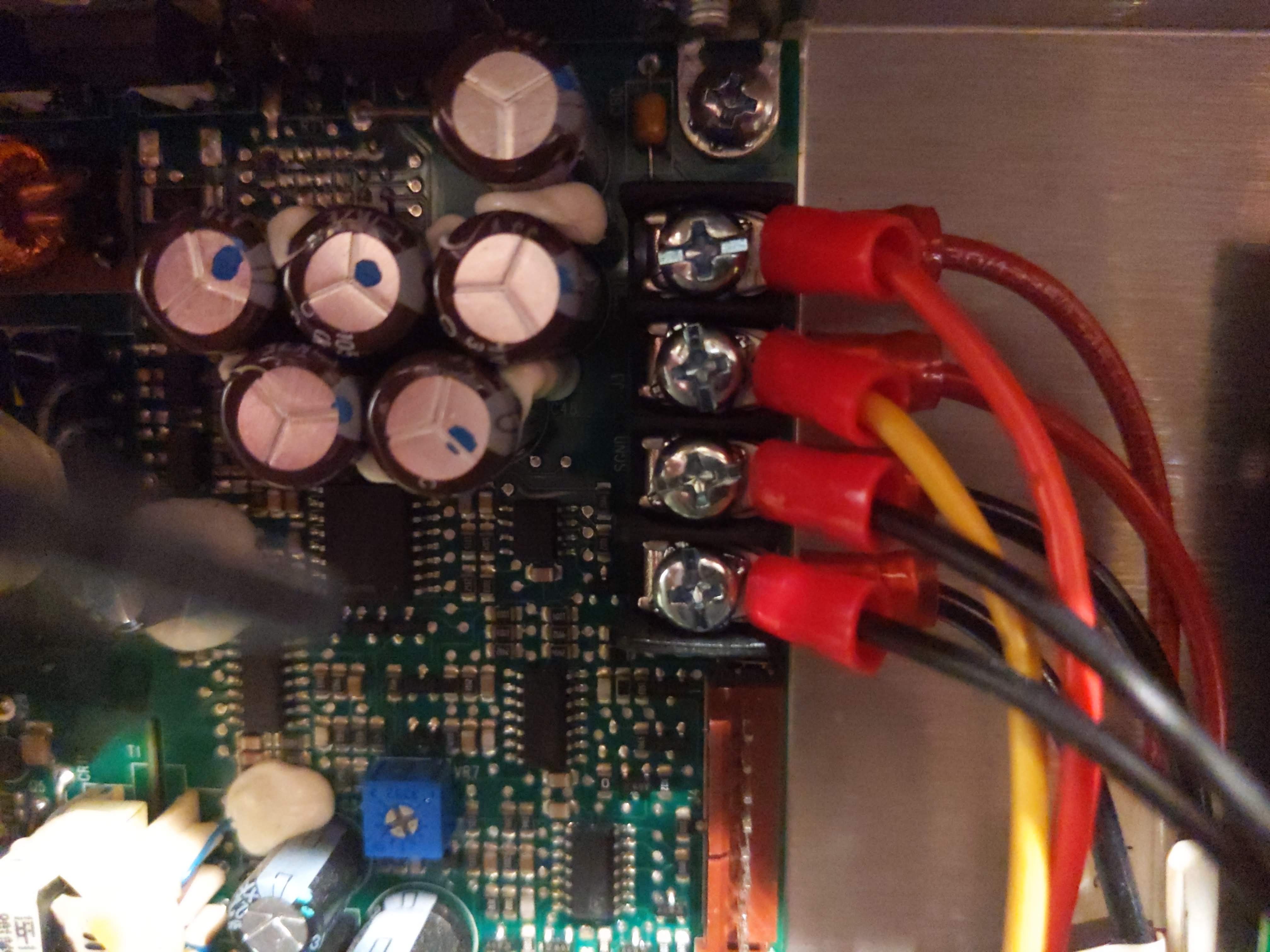
Connect the 24 V power supply to the Duet 2 WIFI, Duex5, and Geckodrive G320X boards.
Open the back of the electronics cabinet to expose the 24 V power supply by removing the single screw.
Using the Y-shaped solderless wire connectors, crimp the connector to the end of the computer HDD wiring harness.
Unscrew the 24 V output wires part way. Insert one red and one black under the 24 V and GND connections. Do the same with the 2nd set under the 2nd 24 V output and GND connections. (One set will go to the Duet 2 WIFI and Duex5 boards. The other will go to the Geckodrive G320X board.)
Crimp the ferules that came with the Duet boards on the other end of the computer wires running from the 24 V power supply.
Make sure the GND wires between the Duet 2 WIFI and the Duex5 boards are kept as short as possible.
Screw the 24 V and GND wires into the power inputs of the Duet 2 WIFI and Duex5 boards.
Using the second set of 24 V and GND wires power the Geckodrive G320X DC servo motor driver. Again do not connect any other wires yet.
Close the back of the electronics cabinet where the 24 V power supply is located and reattach the single screw.
8
Connect the 5V and GND wires to the Duex5 board.
Wire up the additional 5V power supply that runs to the SBC to the Duex5 board.
Move the jumpers on the Duex5 board to select 5 V AUX fan output, 5V end stop, and 5 V AUX External select.
9
Mount and wire in the LIS3DH Accelerometer.
Solder the wires to the LIS3DH accelerometer board.
Cut the wires to about 3 inches in length and mount them into the Cat5e ethernet jack.
Using the clip part of the jack mount the jack onto the zip tie at the top of the printer head.
Remove the screw on the back of the print head holding the wire.
Using the screw and a piece of double stick foam tape, mount the accelerometer on the back of the print head in the same location the screw was removed. Make sure the acceleromter board is in the same orientation as in the pictures. If not, then follow the directions on Duet3D's website for modifying the configuration code to correct for the difference in orientation.
Repeat the process with the 2nd Cat5e ethernet jack using the Dupont connectors for connecting into the thermocouple daughterboard pins as directed on Duet3D's website.
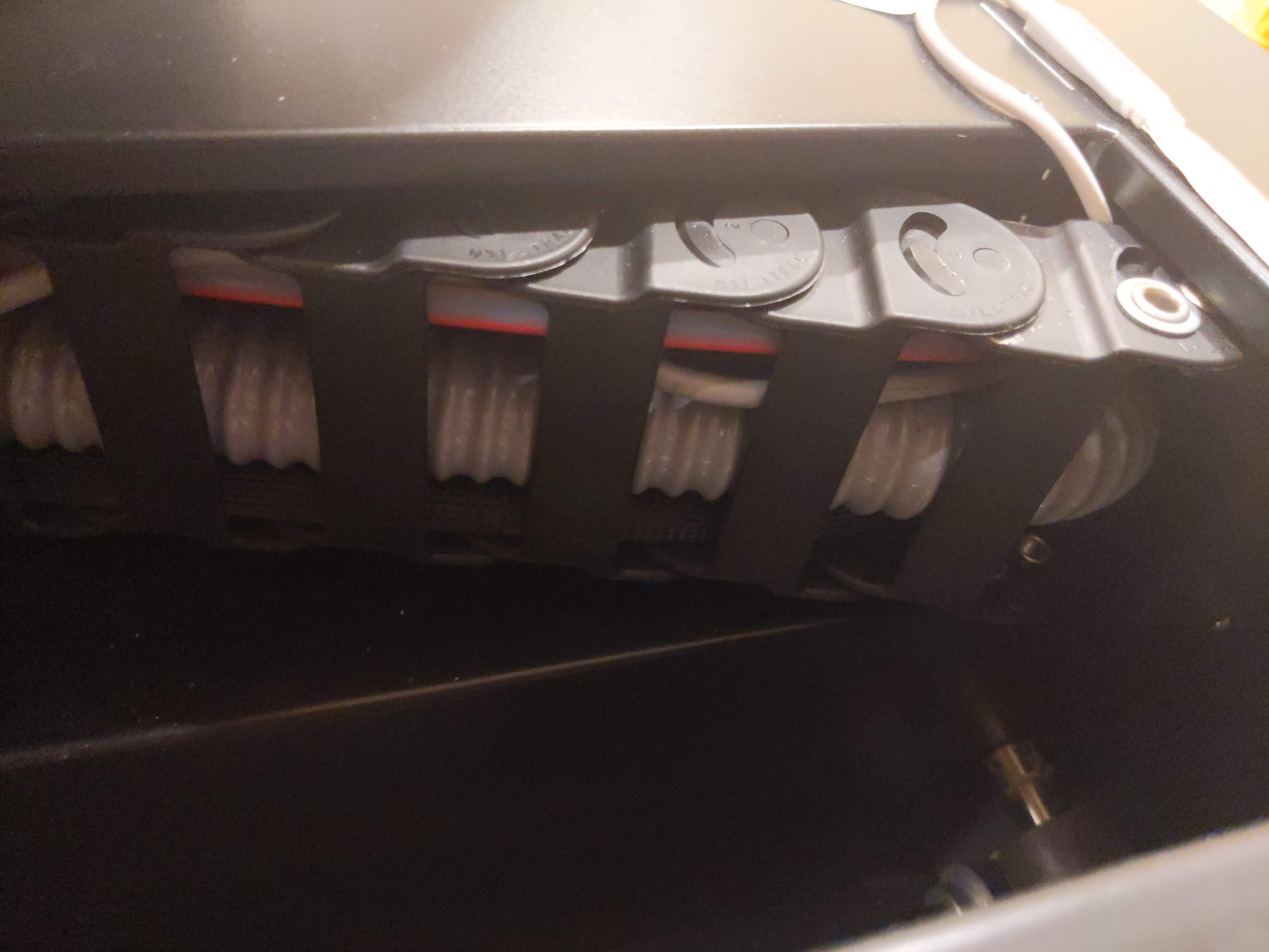
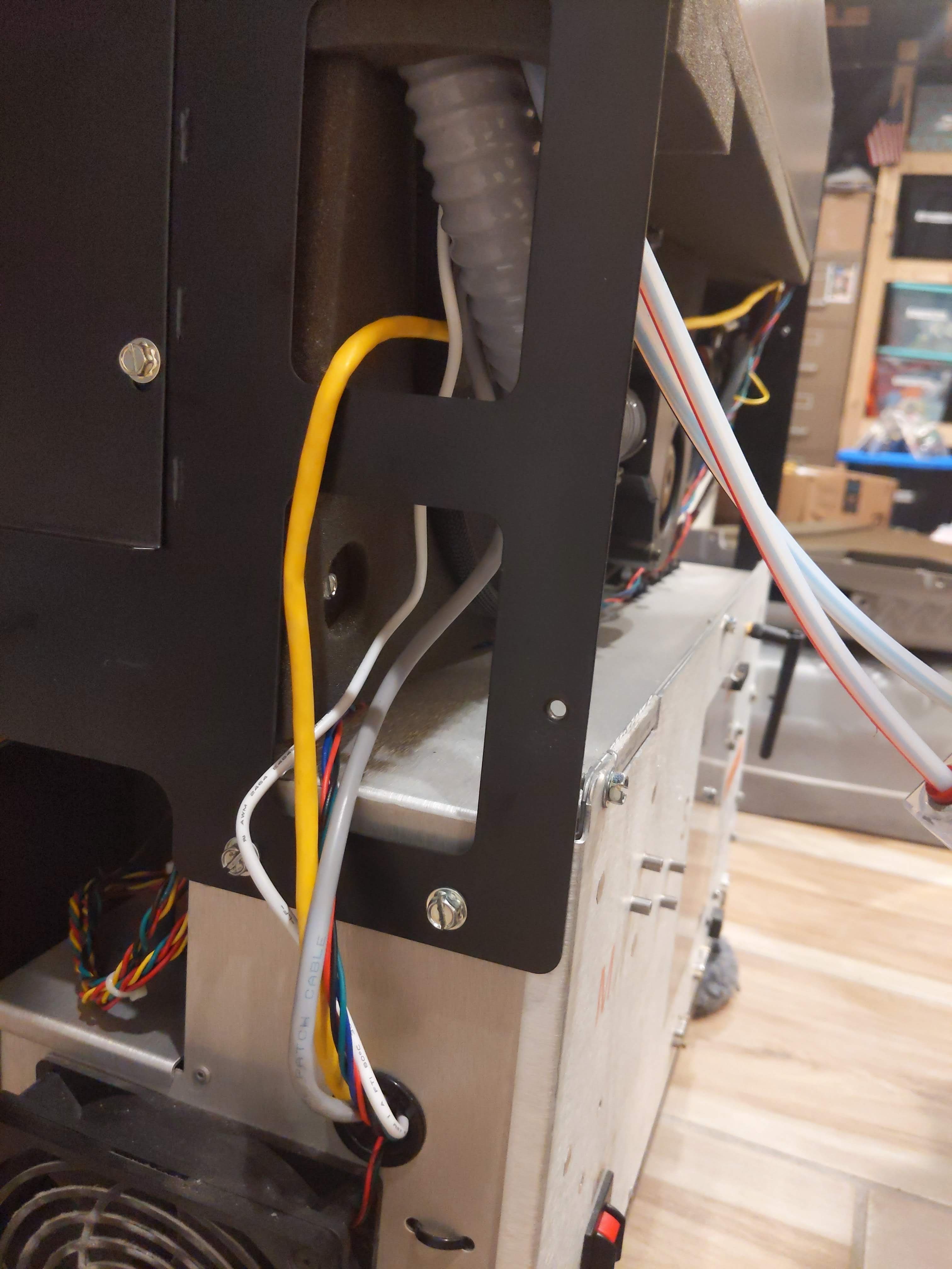
Plug in the Cat5e ethernet cable into one of the jacks and feed the wire through the flexible umbilical feedthough at the top of the print head.
Run the cable to the back of the printer and in through the side grommet.
Plug the ethernet cable into the other jack connected to the Duet 2 WIFI board.
10
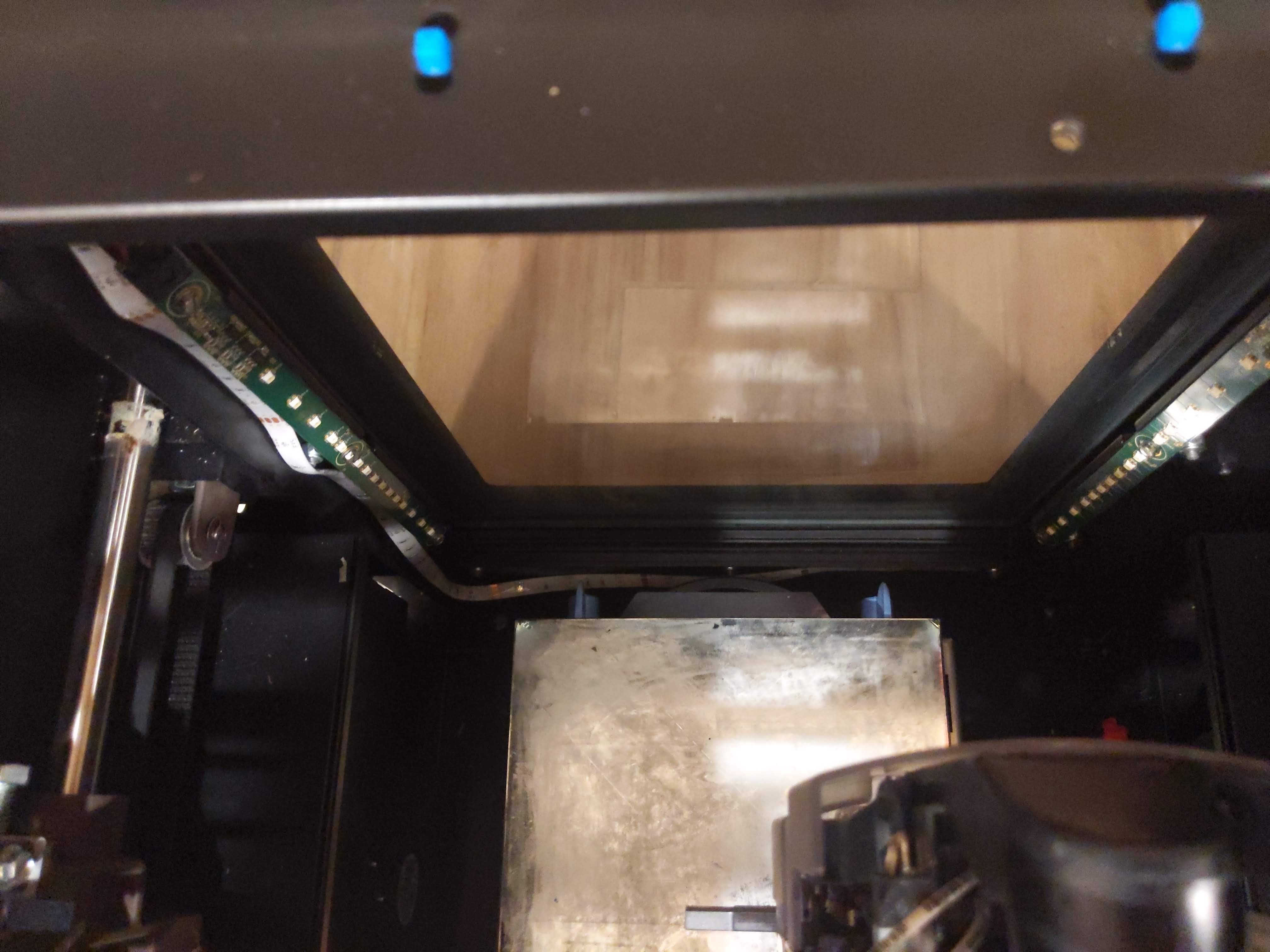
Add additional LED light strip if desired for color control and additional lighting.
Cut the USB end off of the LED strip.
Strip the wires to expose the red (power) and black (GND) wires.
Wire the LED strip in to the 5 V supply that is connected to the Duex5 expansion board.
Remove the adhesive backing and route the LED strip through the back of the 3D printer and along the top metal braces ensuring the LED's are facing toward the build surface. Also adhere the LED light strip around the entrance to the door for added effect.
Once powered on the LED strip can be controlled remotely.
 Jeremy
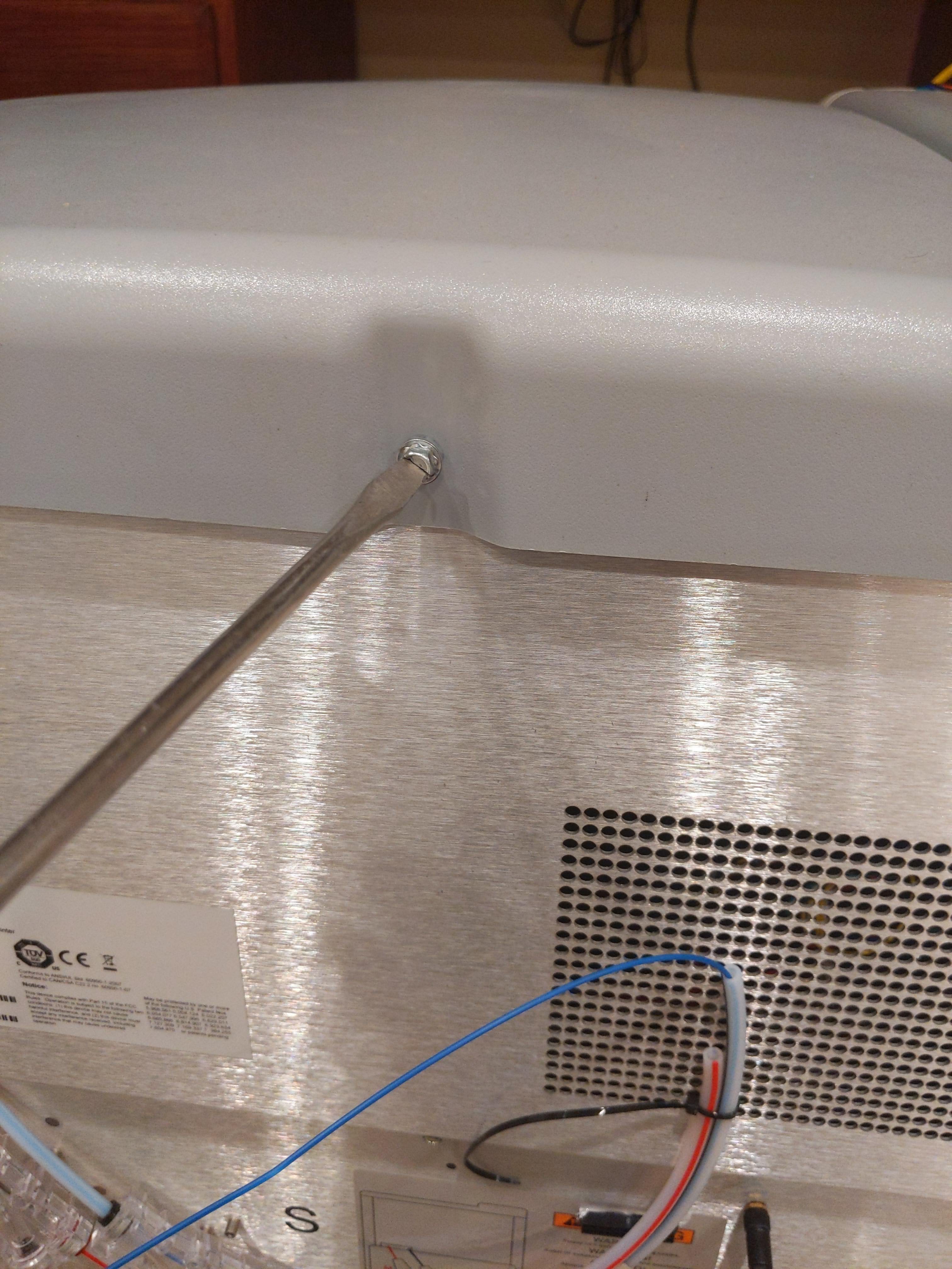


Discussions
Become a Hackaday.io Member
Create an account to leave a comment. Already have an account? Log In.