John Anderson
-
70's Digital Dice Tower
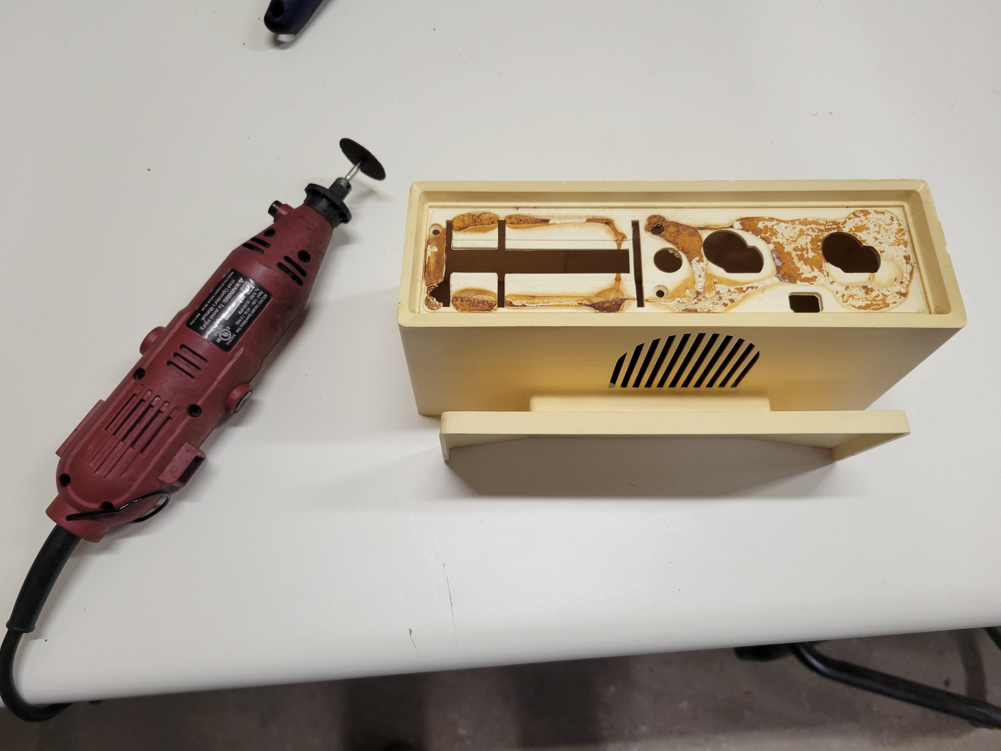
10/23/2022 at 07:05 • 0 commentsI've had this old desktop AM radio case sitting on my shelf for a few years now. I bought it at Goodwill and I loved it's period look. When I saw it, I immediately recognized it's potential as a classic 70's "digital dice tower". So this past week, I finally got around to building the tower I envisioned when I first saw this case.
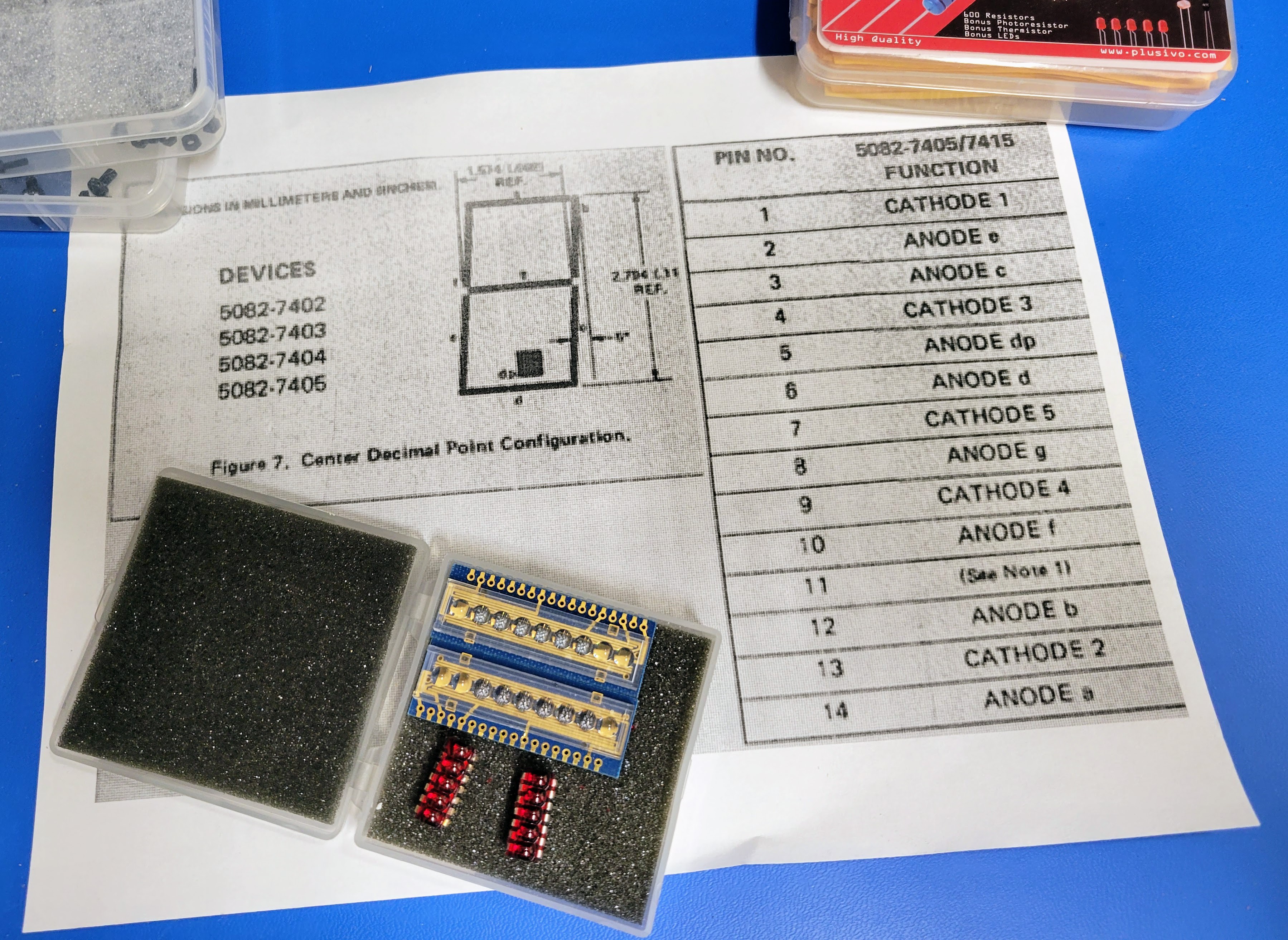
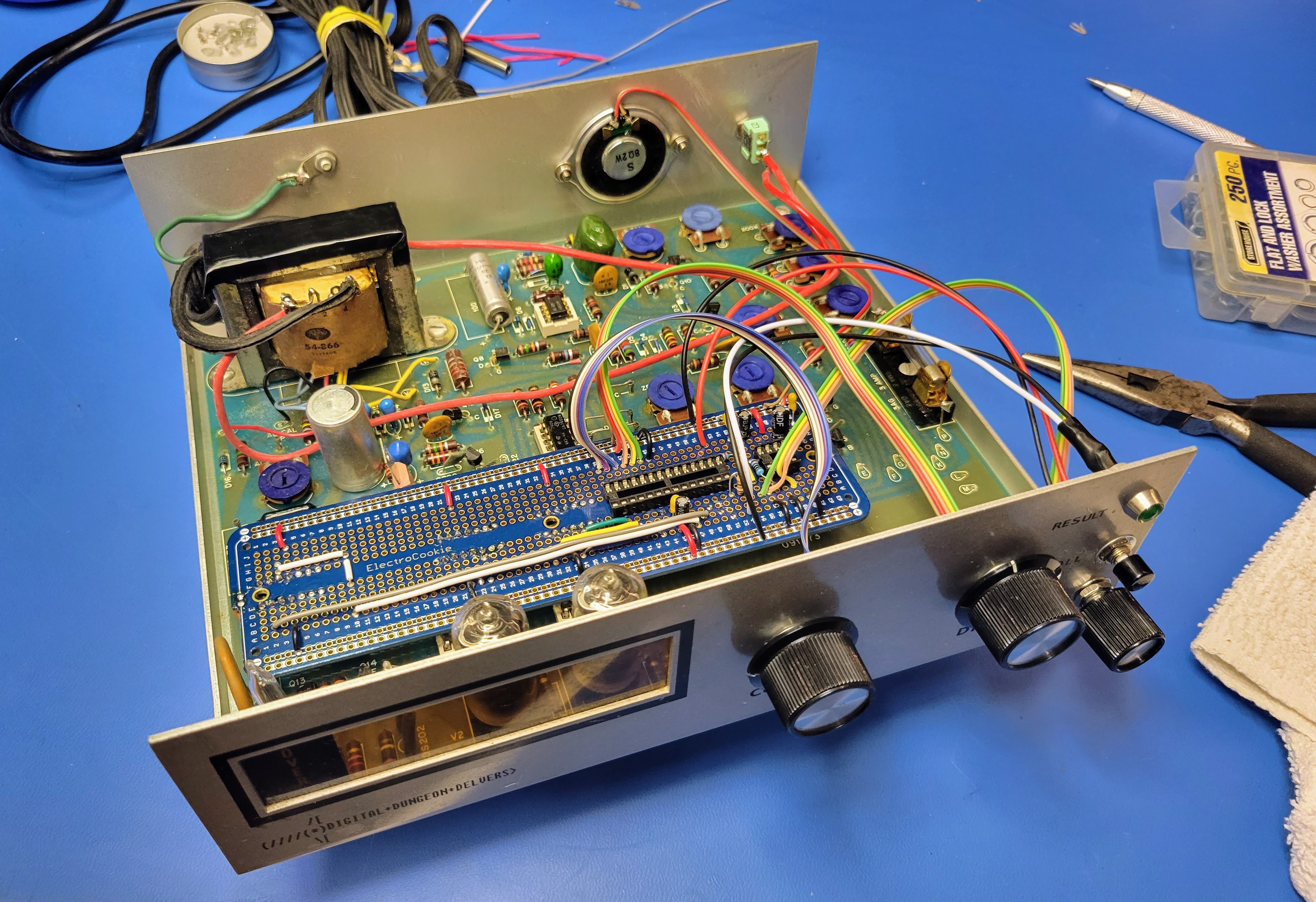
This tower uses the HP 5082-7466 HP MINI BUBBLE RED 5 DIGIT 7-SEGMENT LED DISPLAY. It's perfect for the early seventies period look. It's the same display that was used in calculators and digital watches of the era. The rest is similar to the previous Bell & Howell Digital Multimeter based build I recently documented in the blog. The only differences is a slightly more complex circuit for the LM386 amplifier and a 9 volt battery based power supply. I tried to add more filtering to reduce some of the slight buzz in the speaker. And, I had to add a 7805 voltage regulator to get the right voltage to power the microcontroller and rotary encoders.
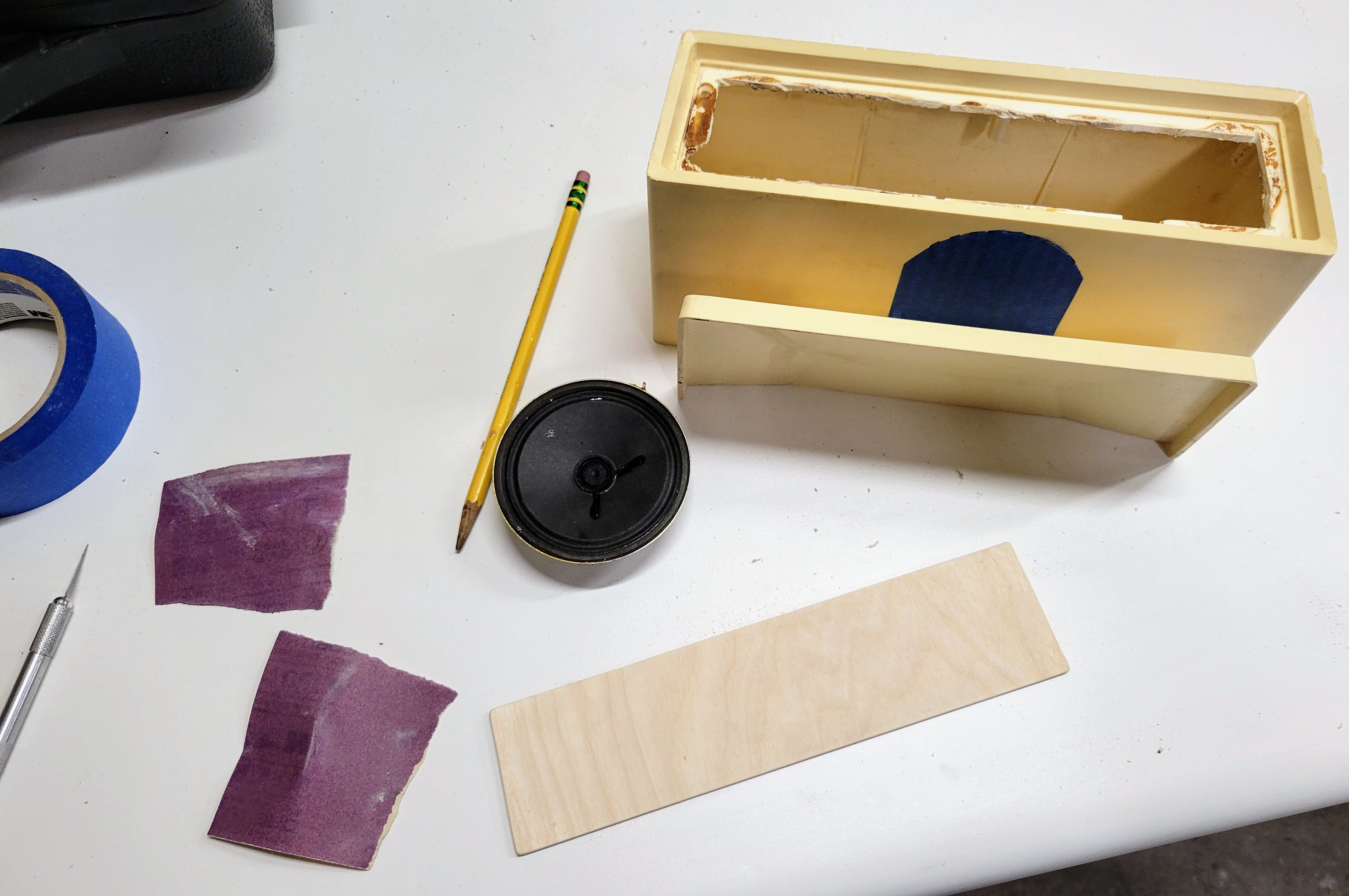
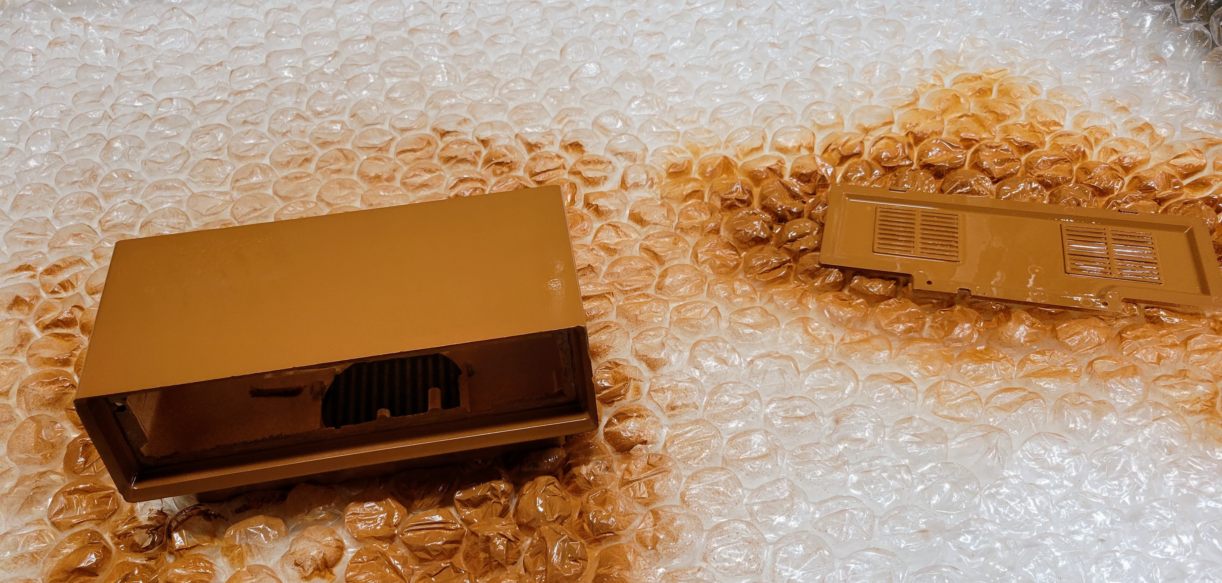
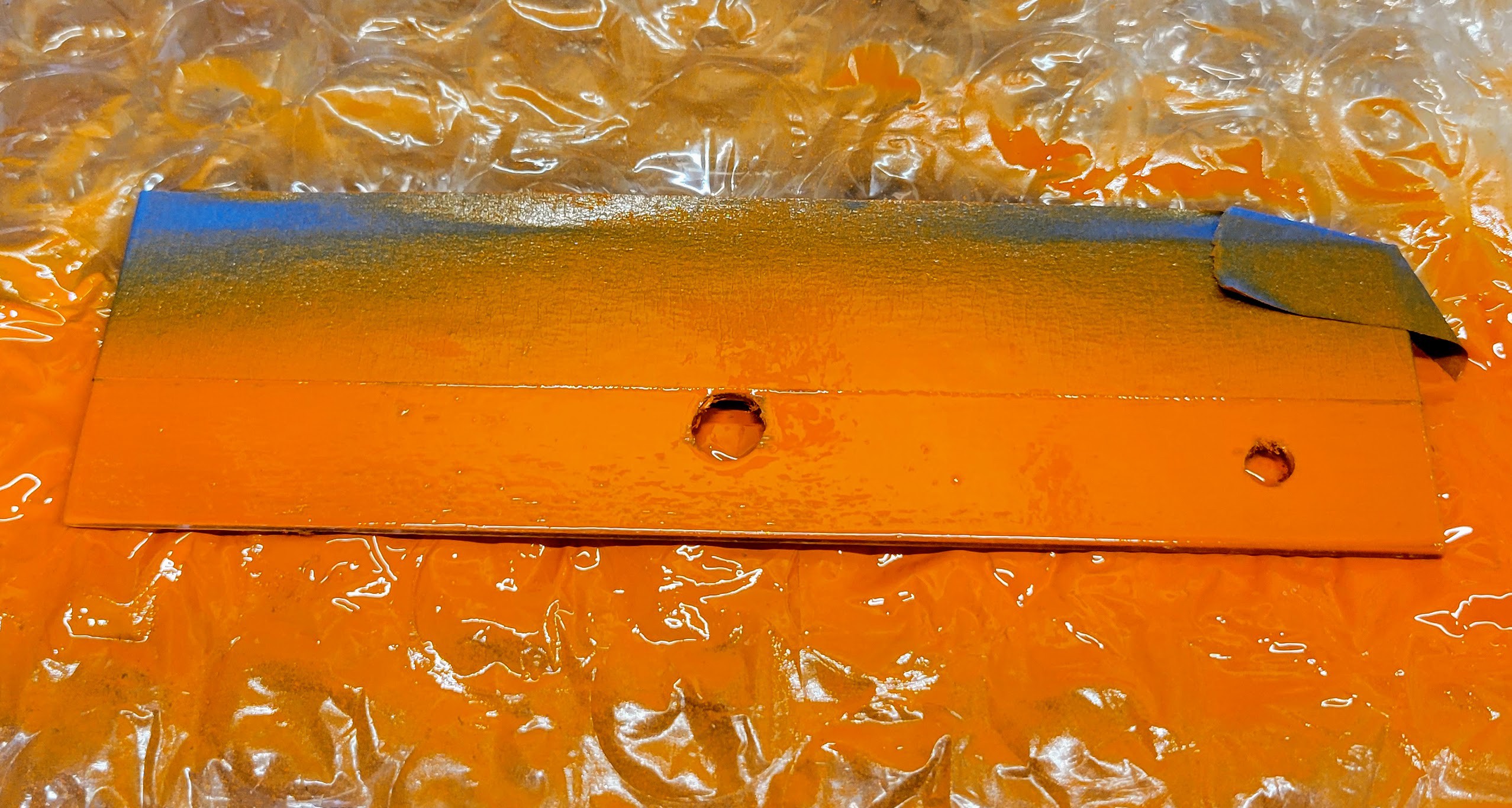
The build started with disassembling the case, painting it, and fabricating a custom faceplate from some thin finishing plywood. The faceplate was then stained and painted in a very fitting 70's color scheme.
![]()
![]()
![]()
![]()
![]()
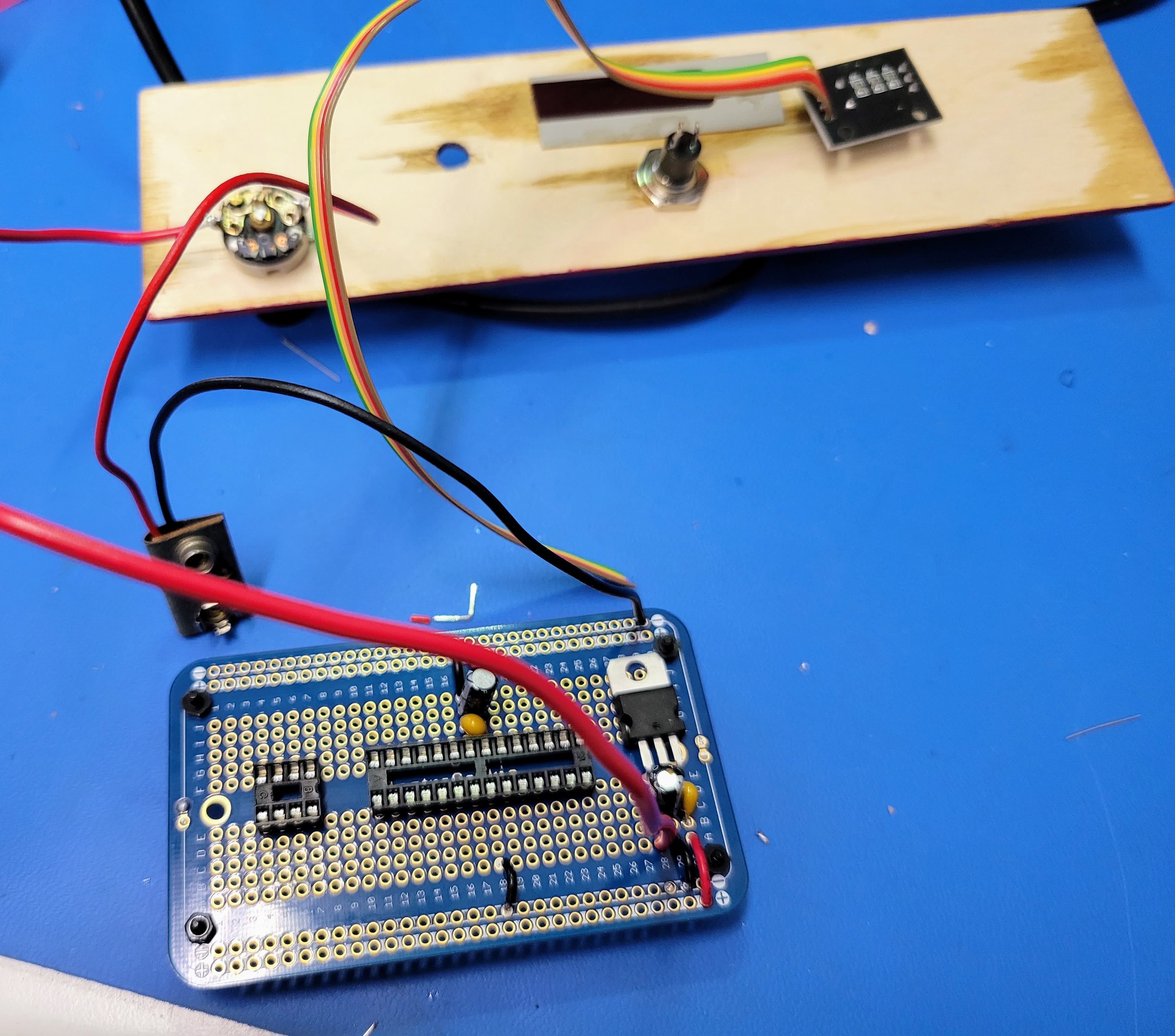
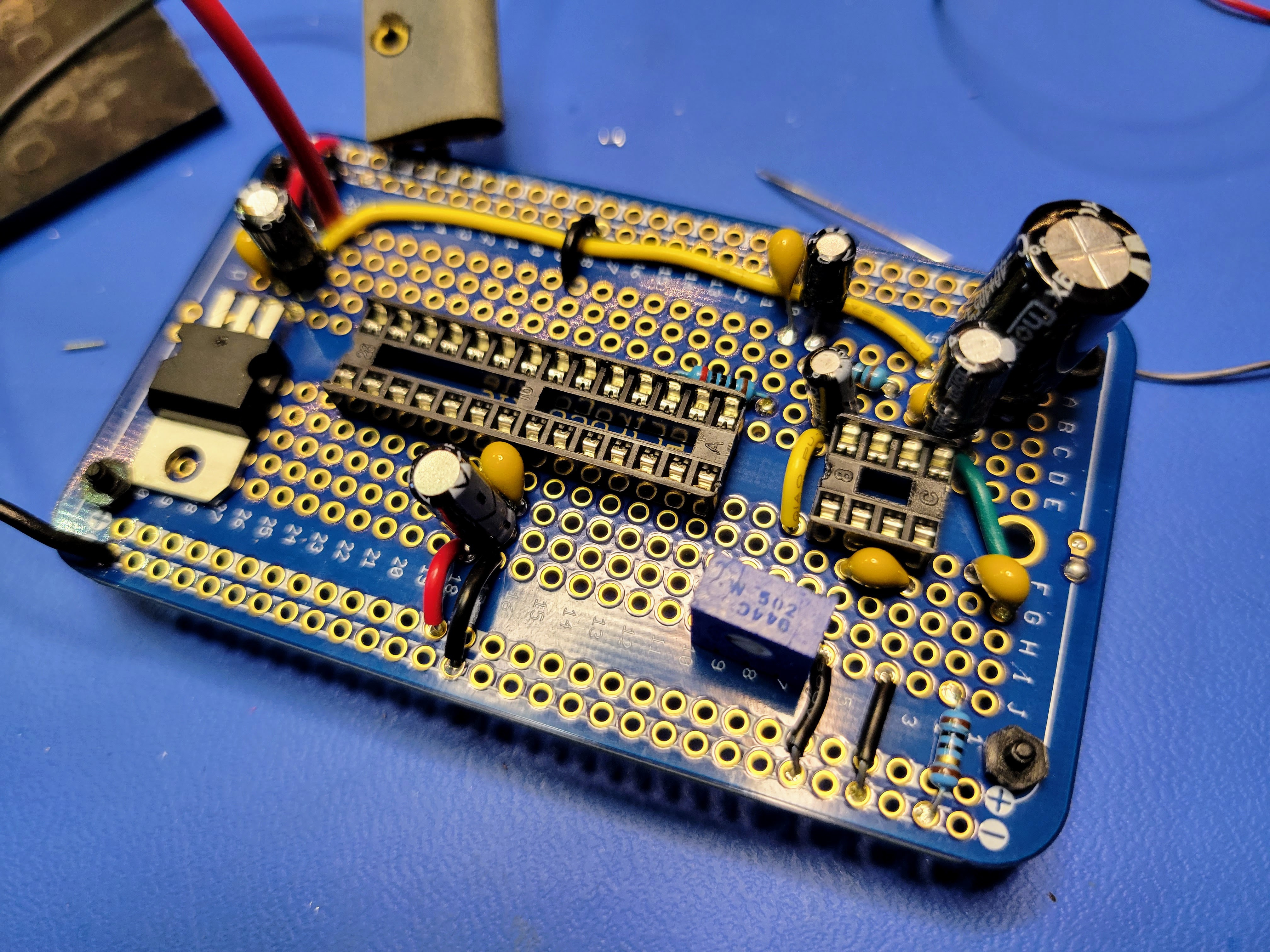
Next, I started assembling the controller board. I started with the power supply based on a 9 volt battery and a 7805 voltage regulator. I also soldered the sockets for the microcontroller and the audio amp to the protoboard. Note: The 10K pot that controls the volume also has a switch to control the 9 volt power to the controller board.
![]()
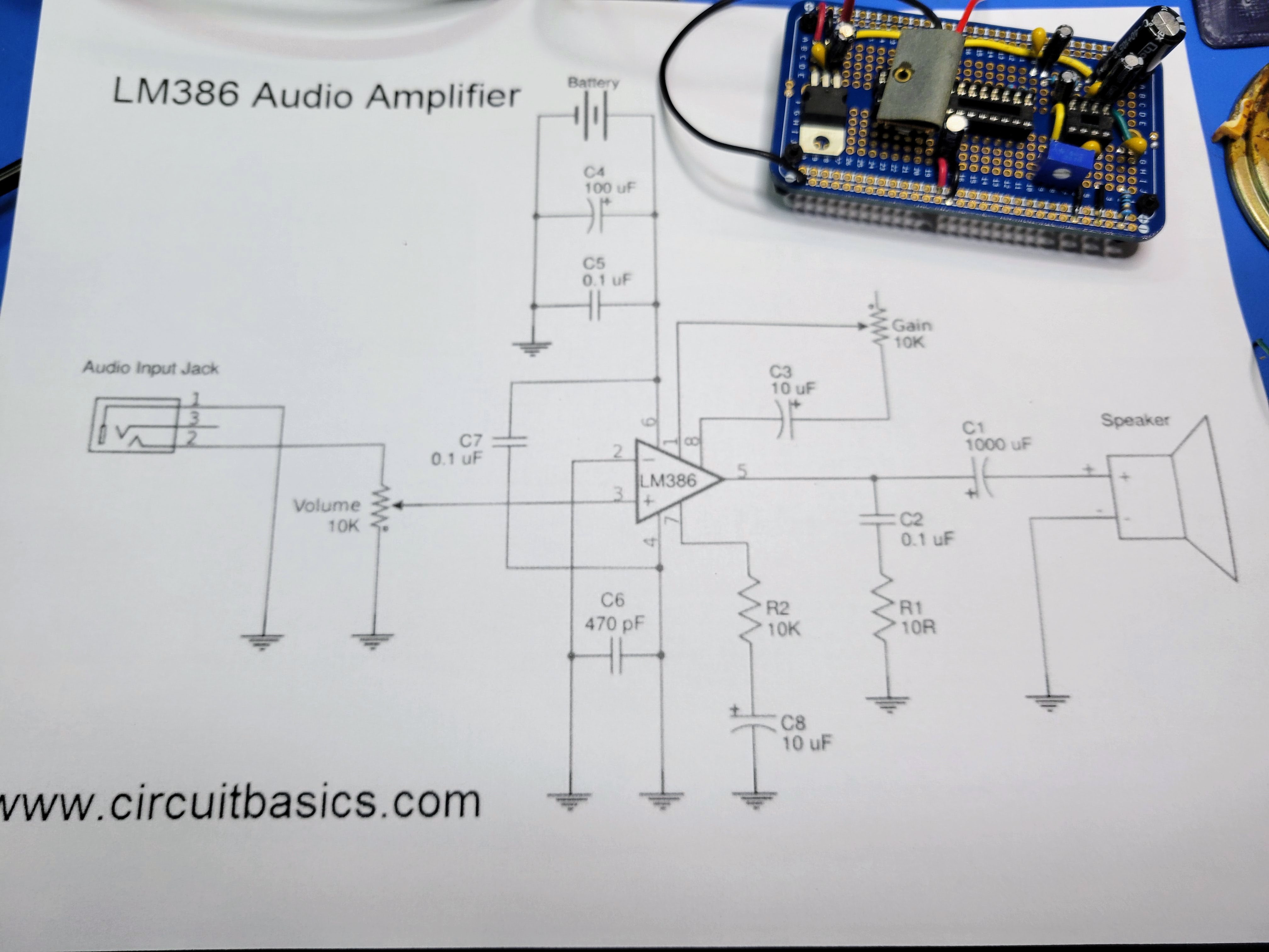
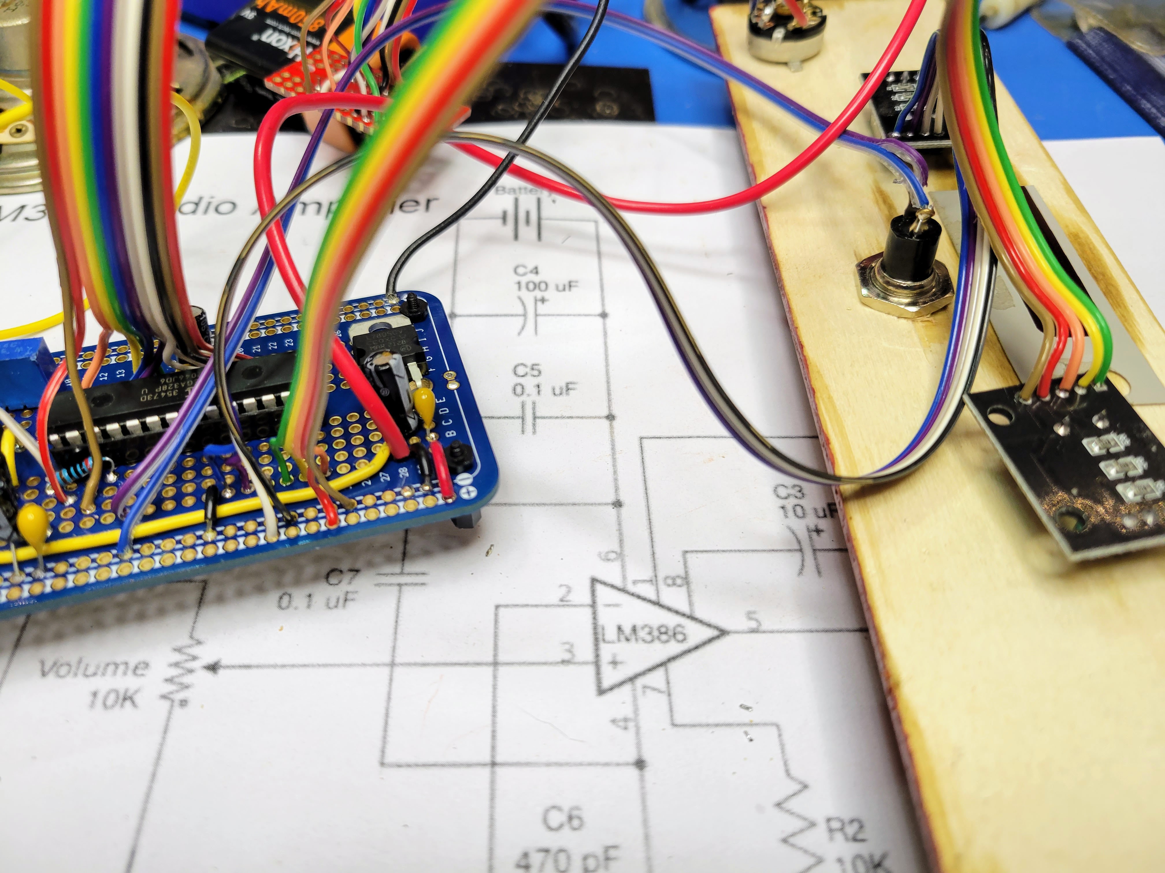
Then I wired up the audio circuit based on the LM386 audio amp. As mentioned above, this circuit was a little more involved than the one I used for the recent Bell & Howell Digital Multimeter based unit. Given the 5 digit 7 segment LED display, this board can be a little more noisy than the nixie display controller. The result was a little disappointing but worked reasonably. I added a 5K pot on the PCB to set the amplifier gain. This helped to tune it so the volume was reasonable and clipping is minimal.
![]()
![]()
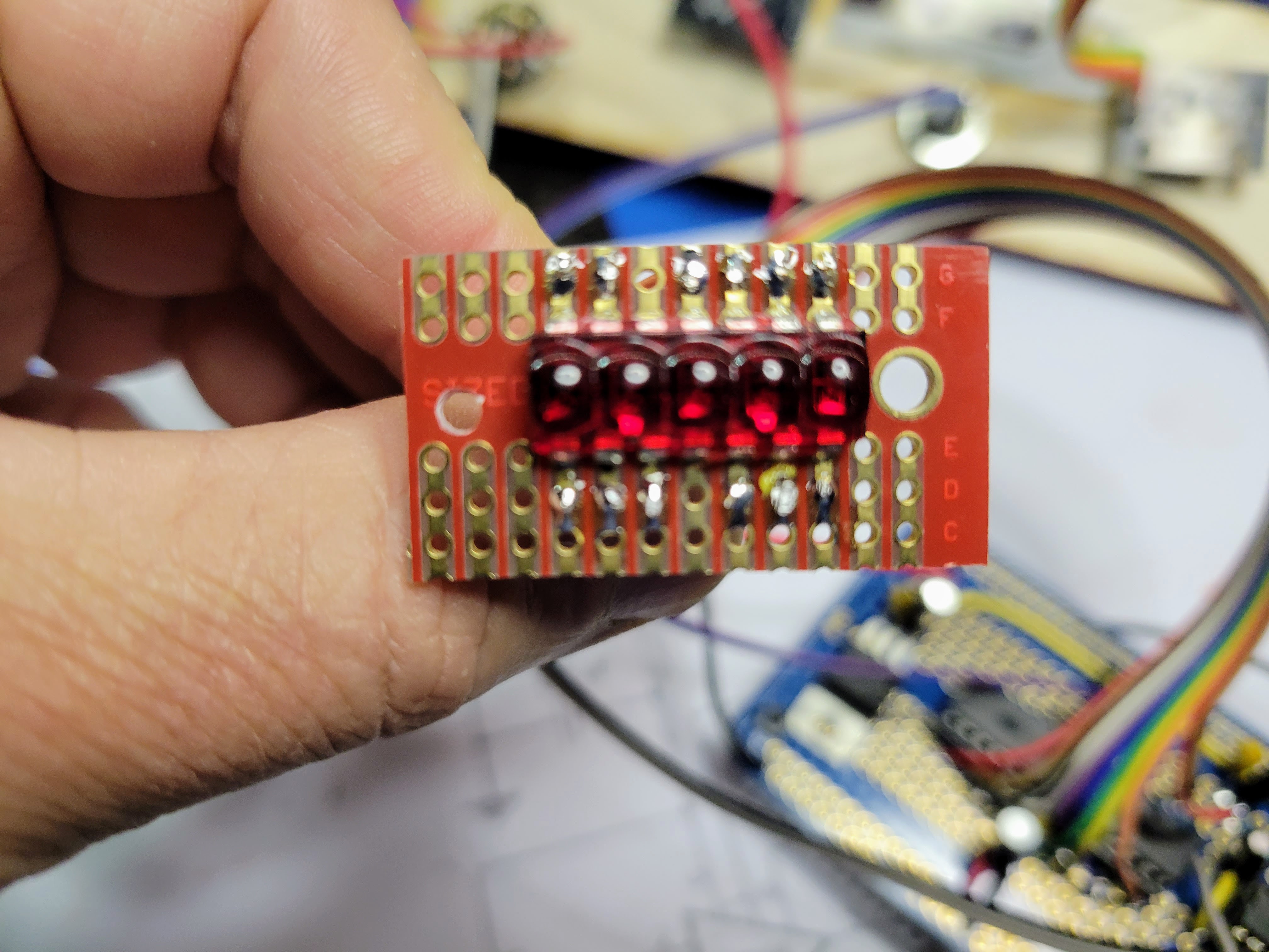
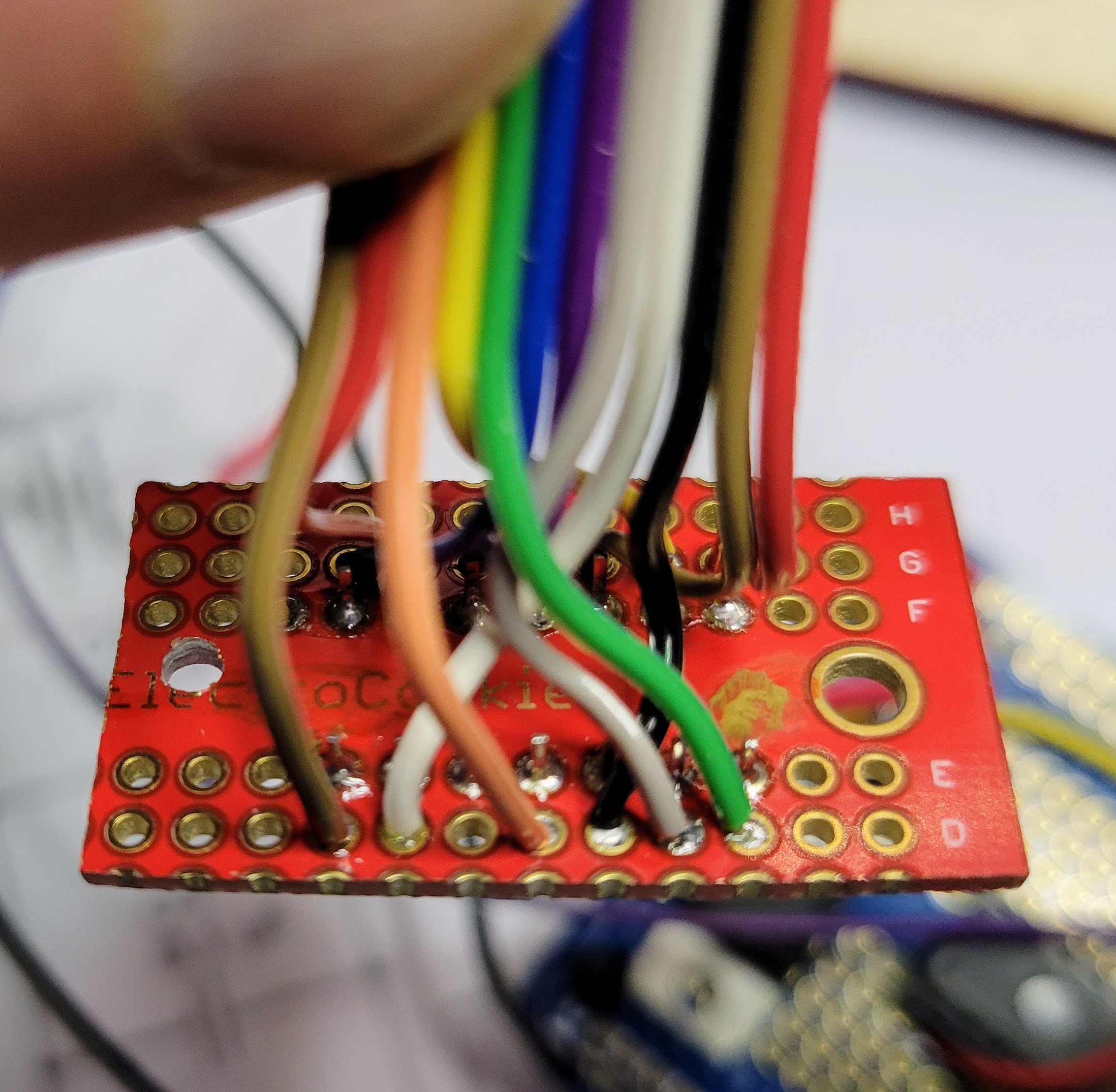
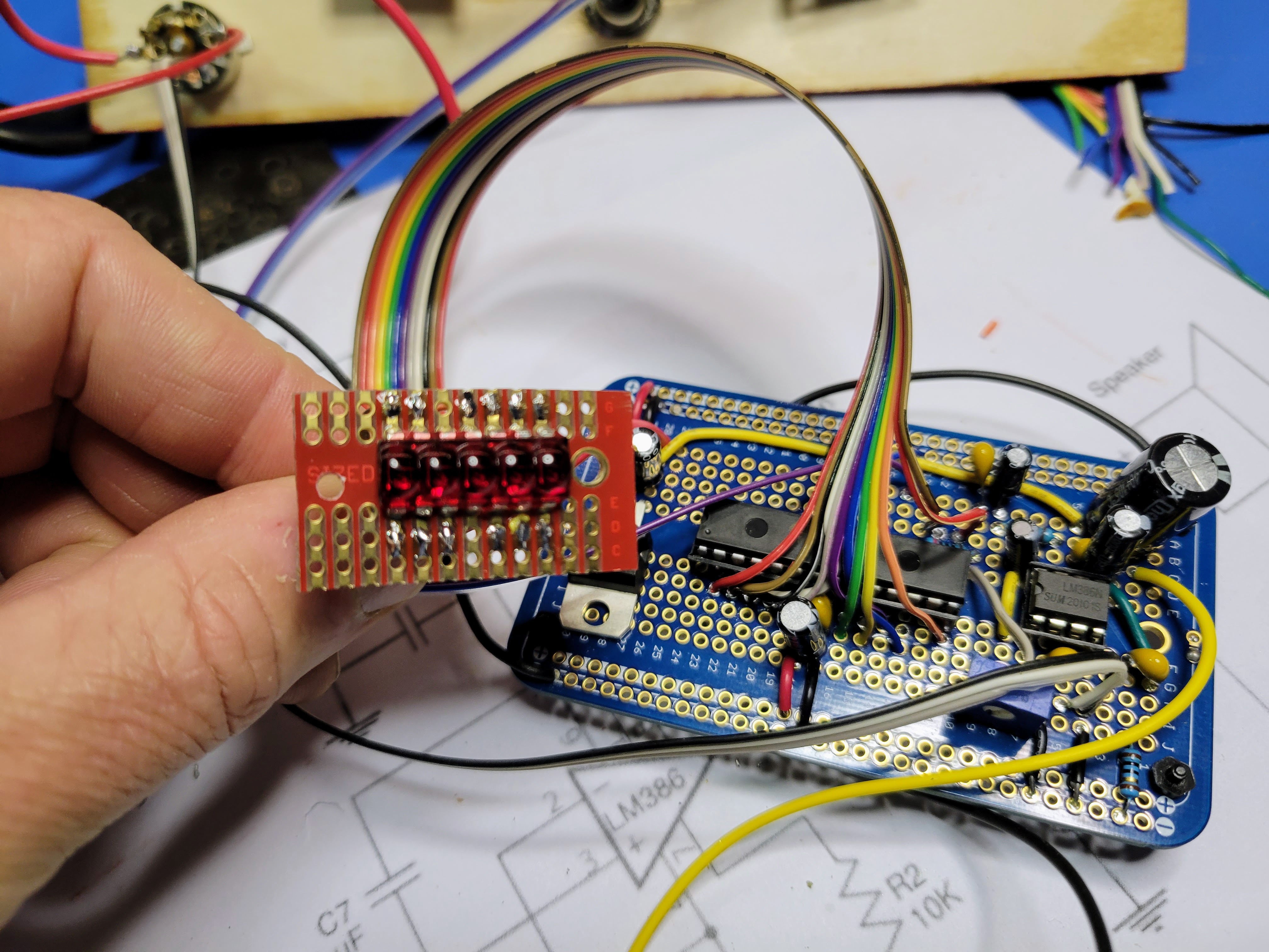
Next, I wired up the 7 segment display. I cut a small protoboard down to size to make wiring and mounting it as easy as possible. Even so, there are 12 wires from the microcontroller to the display (7 segments plus 5 digit commons). The board and wiring started to get a little busy.
![]()
![]()
![]()
![]()
Then for the controller board, I wired up the button and the two rotary encoders.
![]()
Lastly on the controller board, I programmed the AVR microcontroller, inserted it into the 28 pin socket, and inserted the LM386 audio amp into the 8 pin socket. For the Atmel Studio project for this 5 digit seven segment LED type device, download this zip file from the project page.
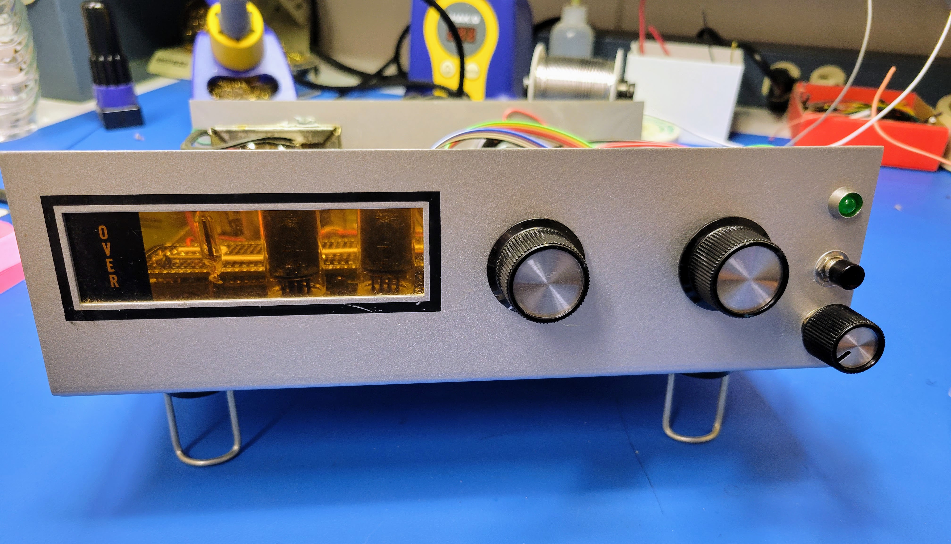
Then it was a matter of mounting everything into the faceplate and assembling the case. A couple short standoffs and some hot glue held the display in place behind a red filter I cut from an old dead piece of test equipment.
![]()
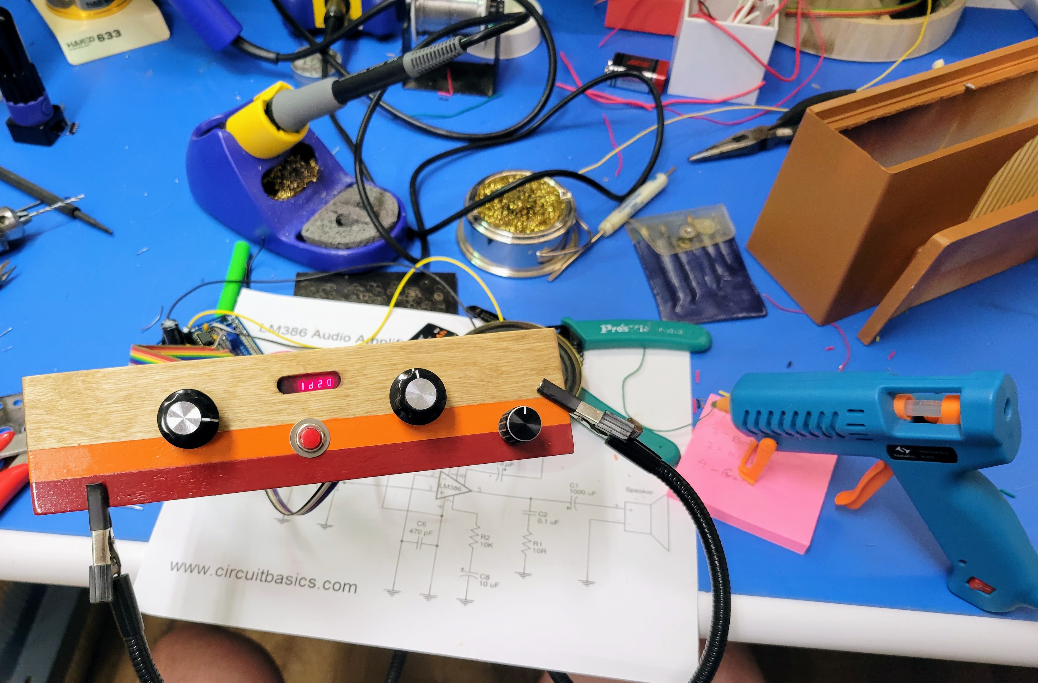
And, here's the result of my efforts.
-
It's Alive
09/13/2022 at 02:38 • 0 commentsNow that it's complete and I updated the build notes to capture a few things I discovered once it was powered it on, let's see what this thing can do!
-
Software and ICs
09/12/2022 at 04:47 • 0 commentsNow that the controller board is built and installed, the next step is to load the application into the MCU flash, install the IC's, and test the device.
Start by downloading the BH_DiceTower.zip file from the project page here. Unzip that into a location in your local storage. You will load the application from there.
If you don't already have it, you will have to download and install the Microchip Studio software next.
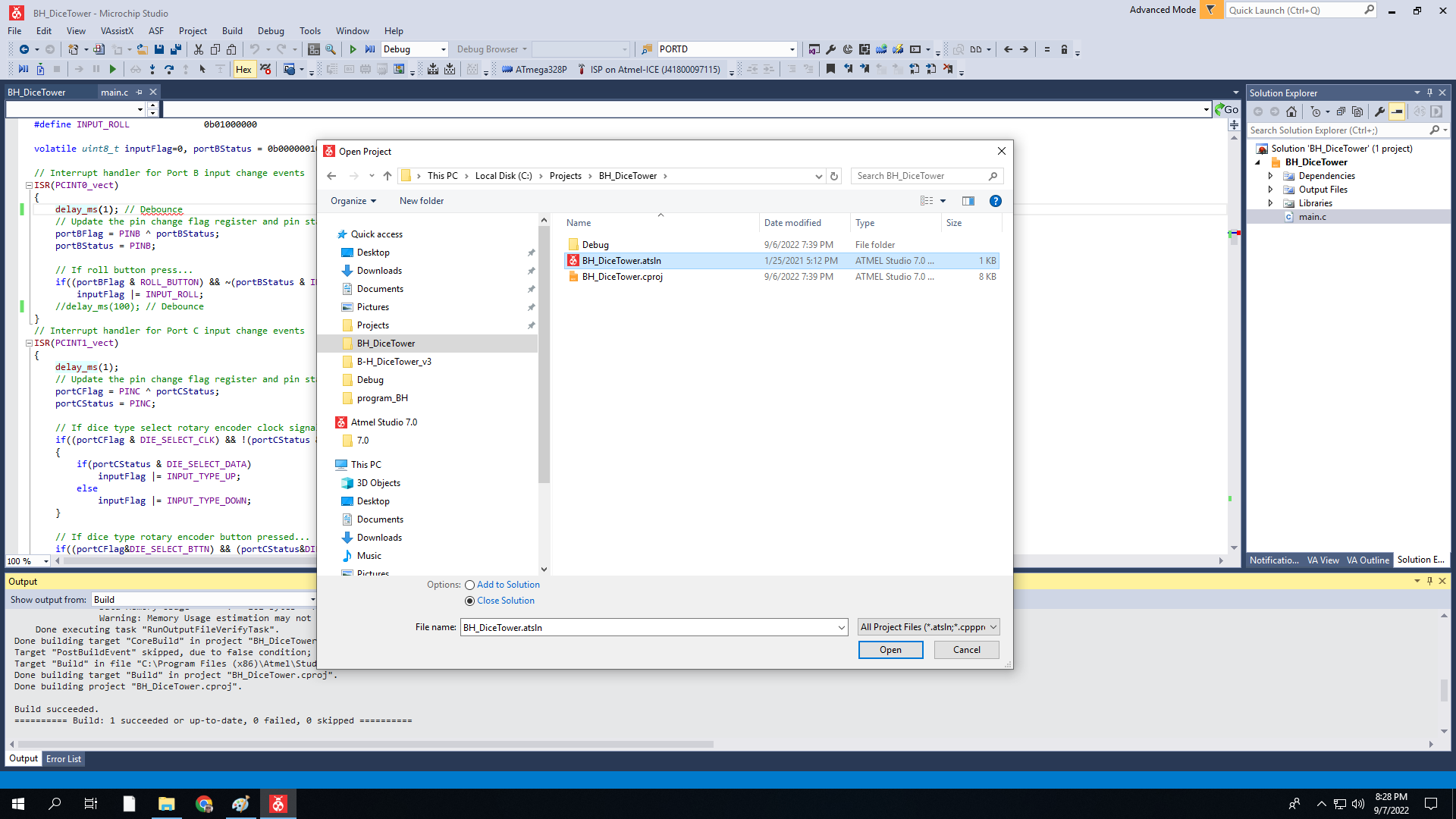
Then, start the Microchip Studio application and load the BH_DiceTower.atsin project.
![]()
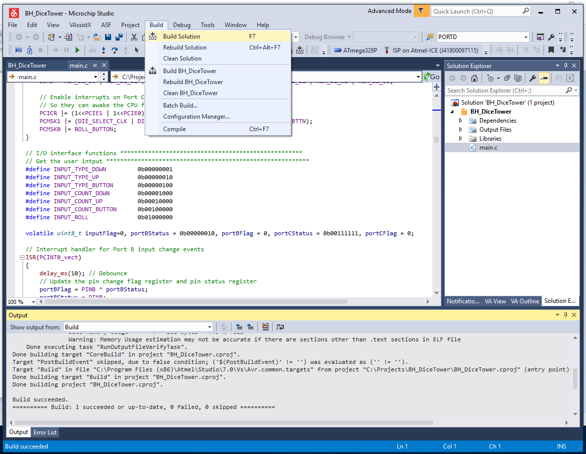
The project comes with the solution already built with .s19 and .hex files that can be loaded to the MCU flash. However if you make changes to the source or simply want to rebuild it, select Build | Buils Solution from the application menu.
![]()
With the source built, the next step is to setup the MCU and program it's flash. To do so, you need a programmer and a board with a 28 pin socket for a ATmega 329P MCU and ISP programming port. I use an Atmel-ICE for my programmer. There are cheaper options, but I can't say enough good things about the Atmel-ICE. It provides seamless debugging for AVR and SAM MCUs using multiple interfaces like ISP and UDPI. If you want use something else, I'll leave it to you to research how to make that work. It's also an option to take the .hex or .s19 files from the project and program the MCU using a programmer with the Arduino IDE. However, I am not familiar with the Arduino IDE. So again, that's left as an exercise for the user.
For the board with the ISP port, I used to add an ISP port directly to the controller board. This is still an option and a little web research will turn up how to wire that up. You can see in one of my previous project blogs where I did just that on a different configuration of the controller baord.
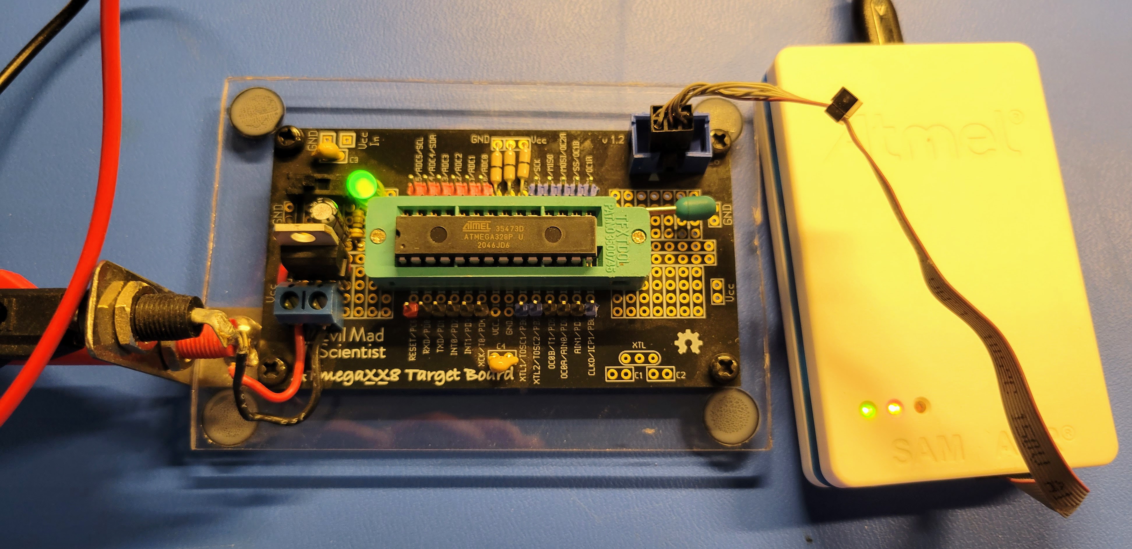
I now use a Evil Mad Scientist ATmegaXX8 Mini Dev Kit (https://shop.evilmadscientist.com/tinykitlist/230). They are cheap and very easy to build. I upgraded my board with a 28 pin ZIF socket, 7805 5v voltage regulator, and mounted it to plexi-glass base with banana connectors for power connect. With this setup, I can use a 12v bench power supply or wall wart and program 328's for use on various boards.
Here's a pic of my programming setup.
![]()
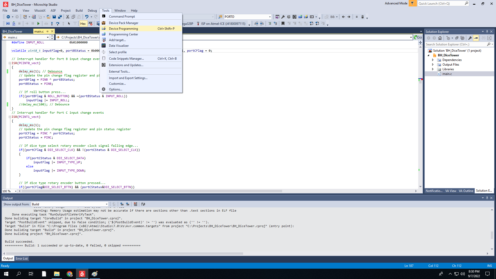
To program the MCU, select Tools | Device Programming from the Microchip Studio application menu.
![]()
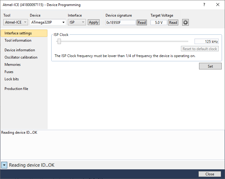
A pop up dialog will appear. In this dialog, select the programmer (Tool), MCU (Device), and programming port (Interface). In this case, it's Atmel-ICE, ATmega328P, and ISP in that order. Then click the Apply button. This will connect to the programming device. Clicking either of the Read buttons will connect the programmer to the MCU using the interface. This will confirm that the MCU can be programmed.
![]()
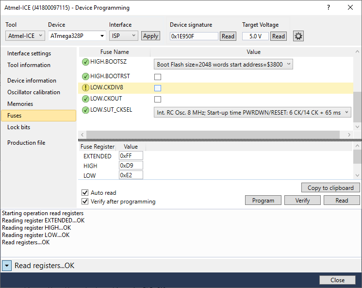
Next, select Fuses in the left pane. In the right pane, scroll down and deselect the LOW.CKDIV8 fuse. Then, click on the Program button below that. The pop up window will report that "Verify registers ... OK" in the bottom status line. This turned off the divide by 8 on the internal clock. If you don't do this, the audio will be garbled. The software's PWM setup assumes this flag is cleared.
![]()
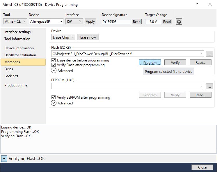
Next, select Memories in the left pane. In the right pane, click the Program button. With the default Interface settings, this step will take about 15 to 20 seconds. When it completes successfully, the status line at the bottom of the pop up will report "Verifying Flask ... OK". At this point, the MCU is programmed. So, turn off power on the board and remove the MCU.
![]()
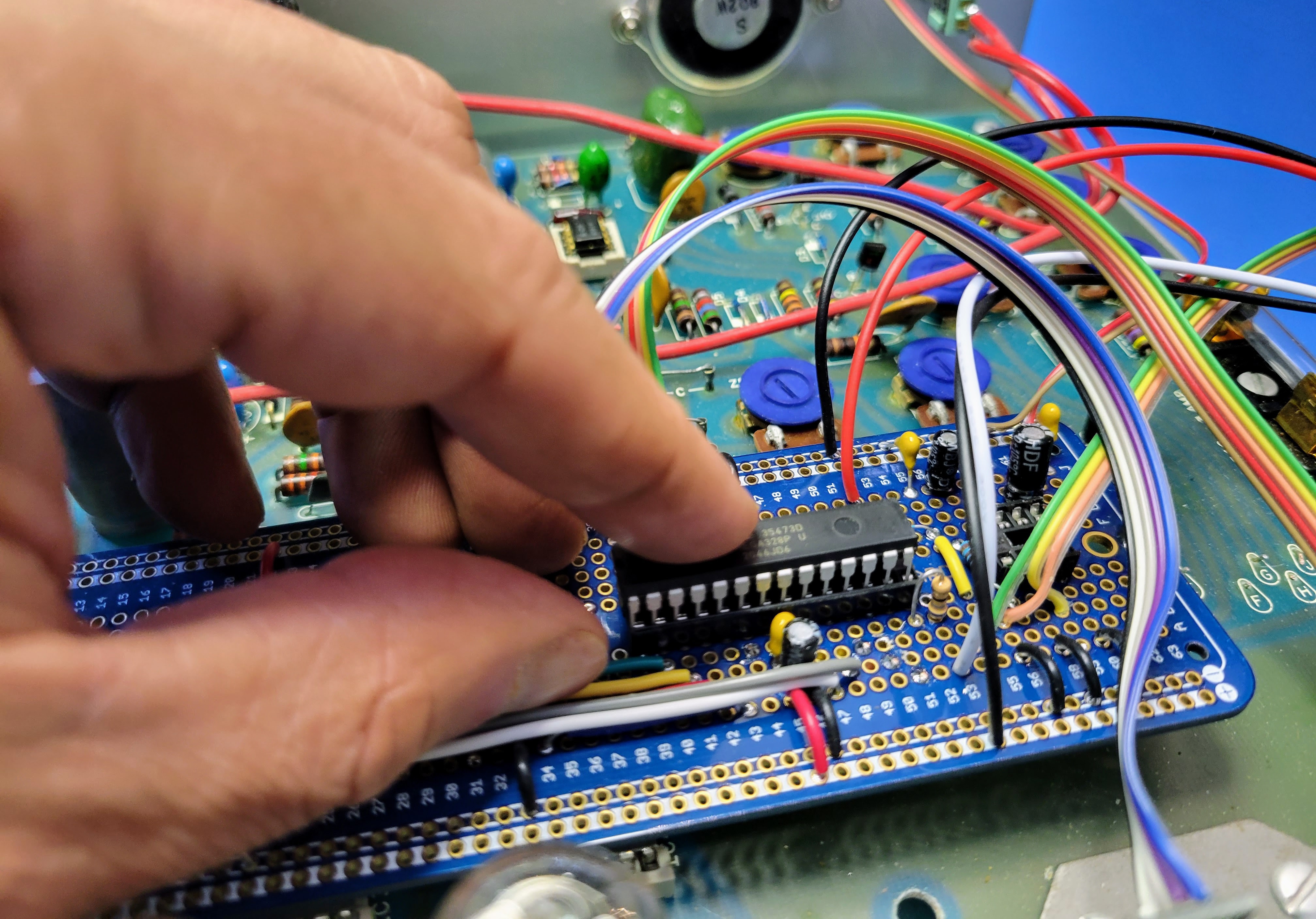
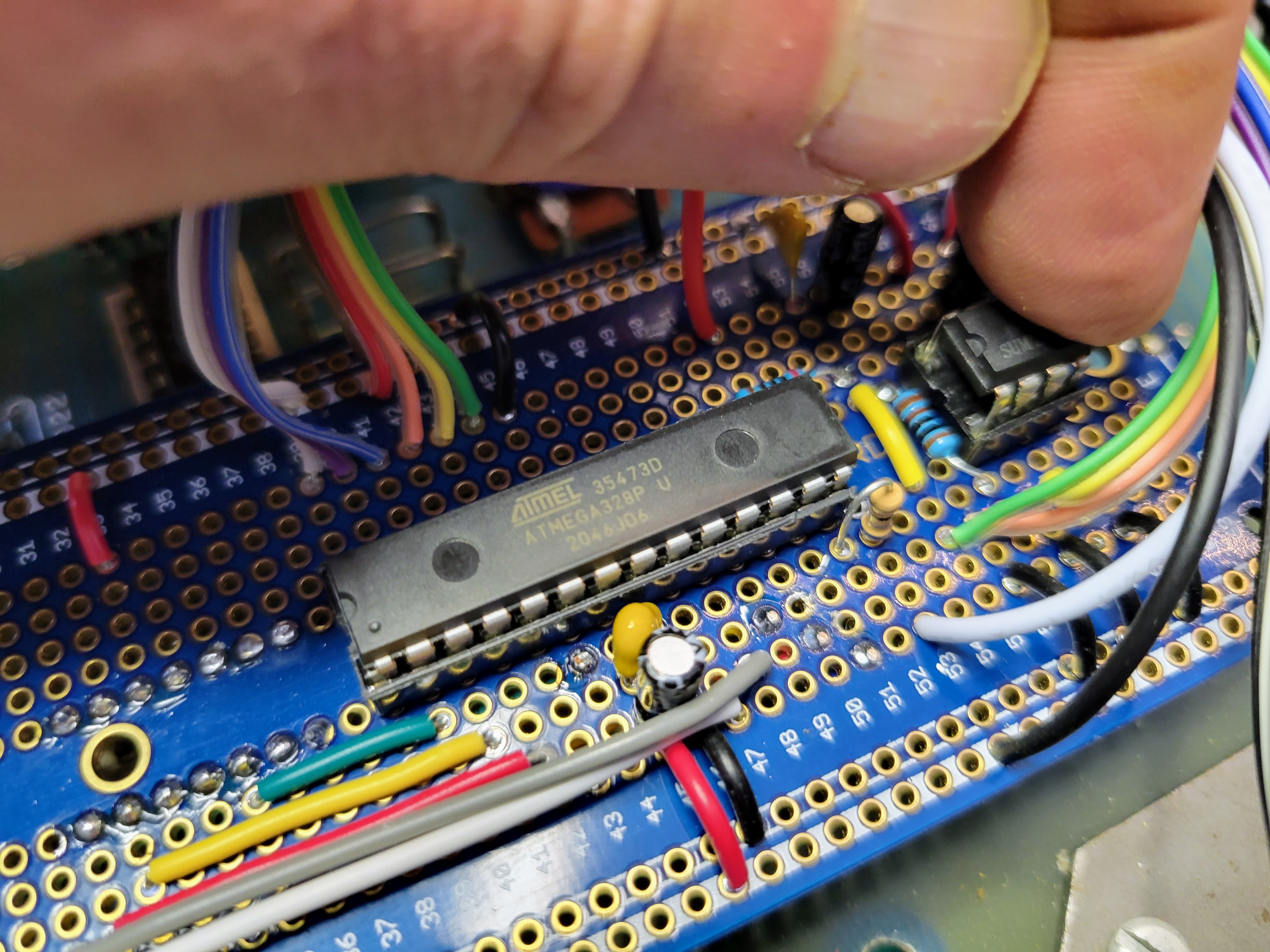
Next insert the MCU in the 28 pin socket on the controller board, paying attention to where pin 1 is correctly located. Note: this end of the controller board is not supported and simply pressing the IC into the socket will dislodge the controller board from the PCB sockets. So, support the end of the controller board with your other hand/fingers as you locate and press the IC into the socket. The same goes for the audio amp IC.
It's an option to install stand-off on this end of the controller board and mount them to the PC. These would need to be very small standoffs.
![]()
Then insert the 8 pin LM386-1 audio amp IC into the 8 pin socket. Again, pay attention to the correct location of pin 1.
![]()
At this point, the controller board is complete. Replace the case top cover and thread the 4 screws in place to hold the cover. Then, turn on the device and see/hear the glory of the Digital Dice Tower.
Caution: If it doesn't work as expected, care must be used while debugging the circuit with the power on. Inside the case there is 120 volt AC and 170 volt DC. These can and will cause injury if you short them across your fingers, hand, body, etc. The controller board itself is relatively safe to probe and touch while operating. It's all 5 volt logic and analog signals.
Note #1: I purchased a set of inexpensive LM386 audio ICs from a source on Amazon. Of the 10 ICs I purchased, only 5 of them were functional. It took some experimentation to figure out which worked. I highly suggest sourcing those from a reliable source.
Note #2: I purchased the rotary encoders from a source on Amazon as well. I have had some bad luck with those as well. Of the 4 batched of 10 I have purchased. One complete batch was non-functional. In the current batch of 10 that I am using for boards, 1 of the 10 was non-functional.
Note #3: I missed wired the result LED originally. You can see it in the picture above. The ground wire was connected to the 5v bus. This did not cause any damage to the controller board or the LED. But, I did have to re-land it on the ground bus to get the result LED to work correctly.
-
Mechanical Assembly
09/03/2022 at 06:55 • 0 commentsNow we'll apply graphics, install the controller, mount speaker, LED, and controls.
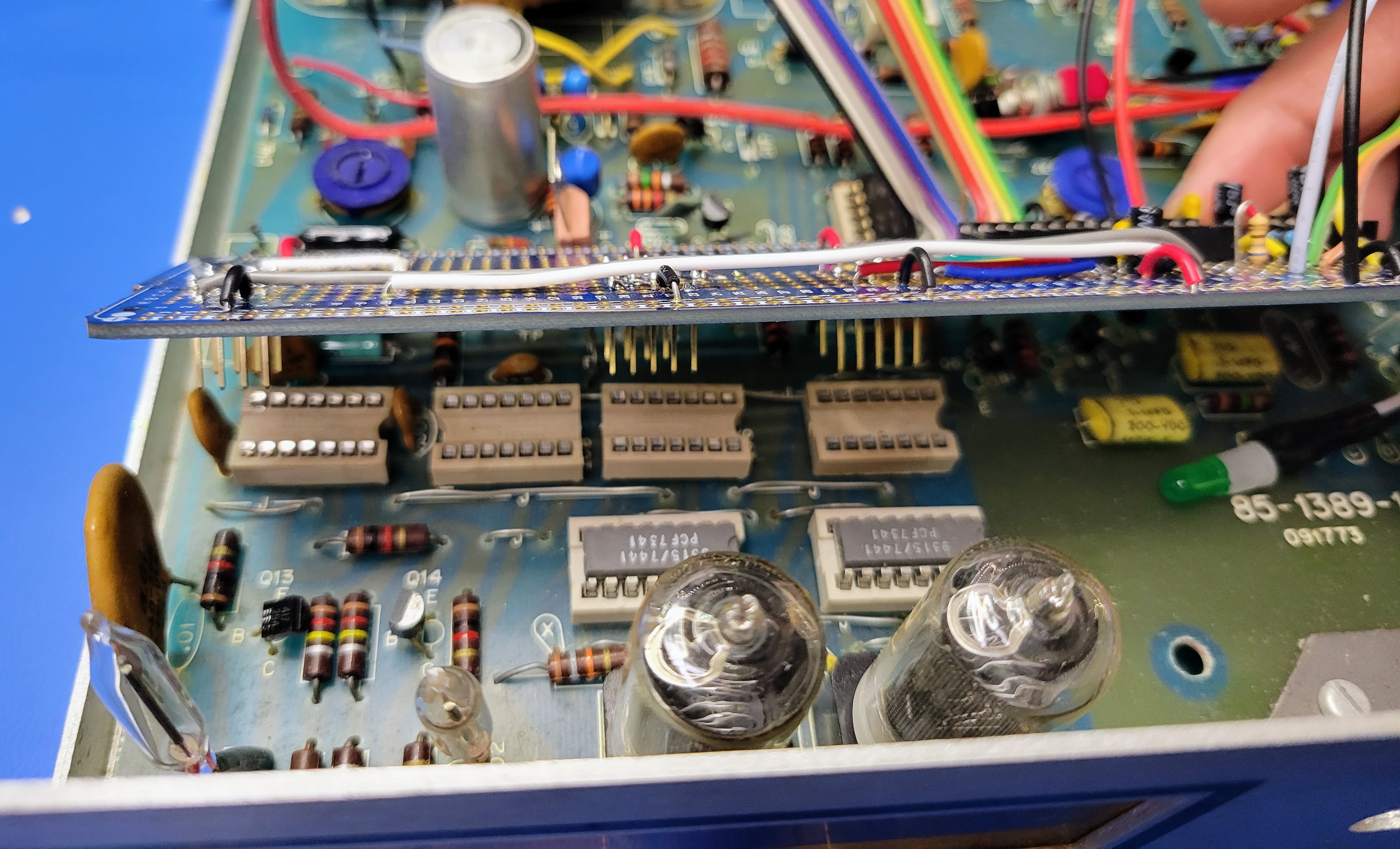
Start by installing the controller board back onto the PCB. Be careful to line up the header pins with the socket on the left. With that one lined up, the rest of the headers should line up as well. Lightly press the controller board into place. It won't take much pressure.
![]()
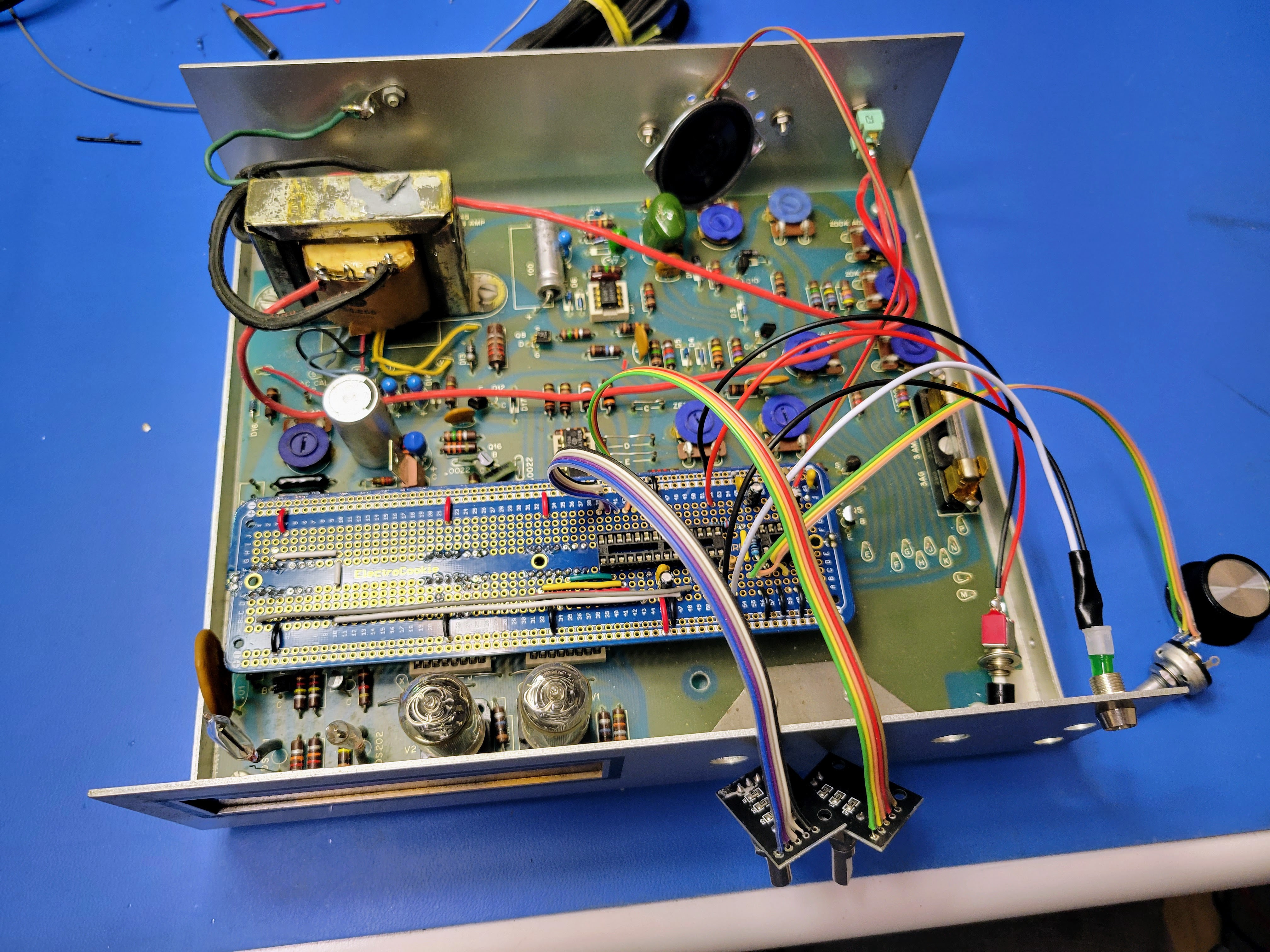
Once the controller board is in place, everything should look like this.
![]()
Next, mount the speaker to the holes drilled earlier. A stash of small screws, washers, and nuts is helpful here. I always keep all screws from disassembling other vintage electronics.
![]()
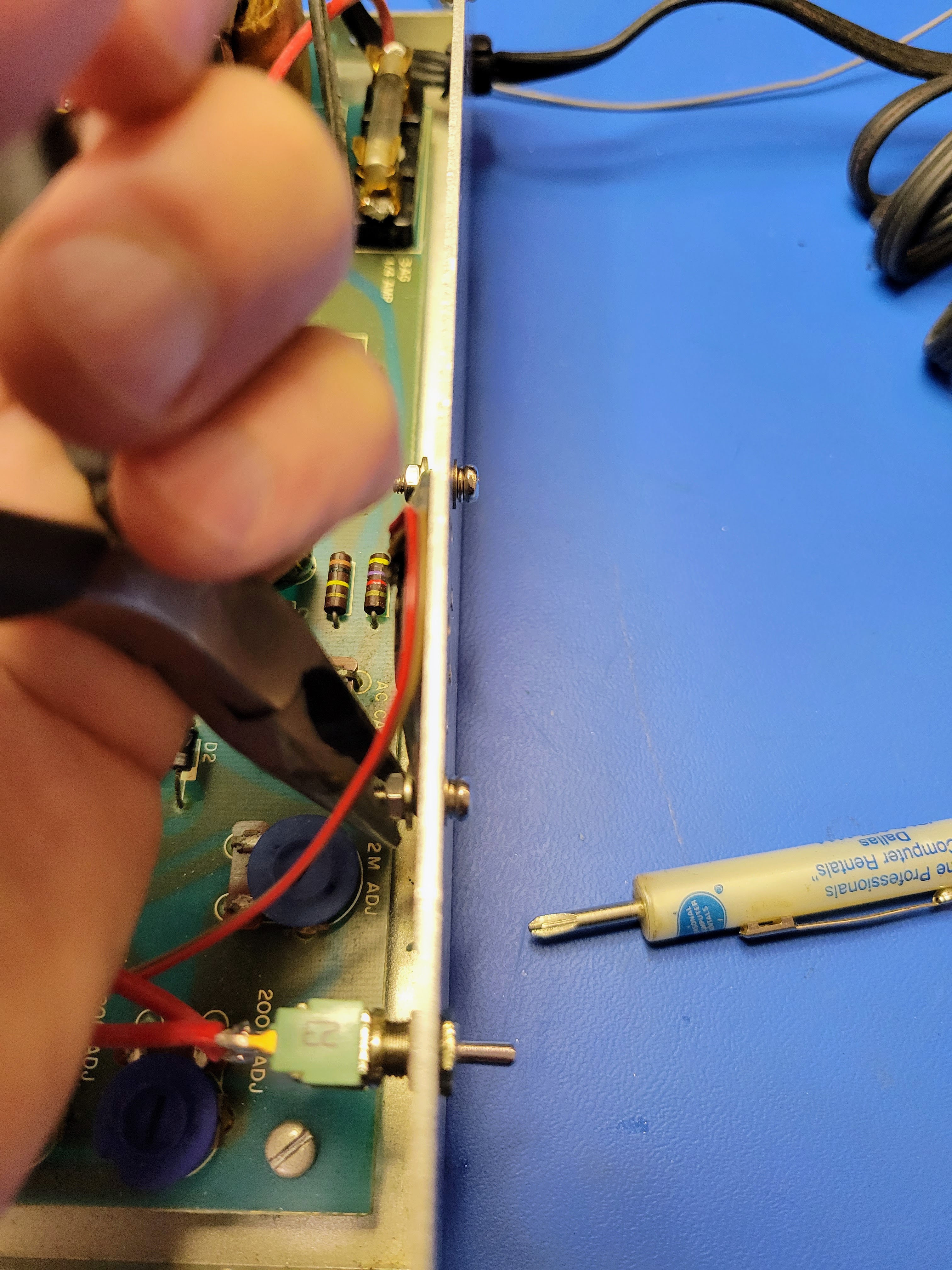
Use a pair of needle nose pliers and a screw driver to get these screws nice and tight. If they are loose you'll get some rattle in the voice/sound.
![]()
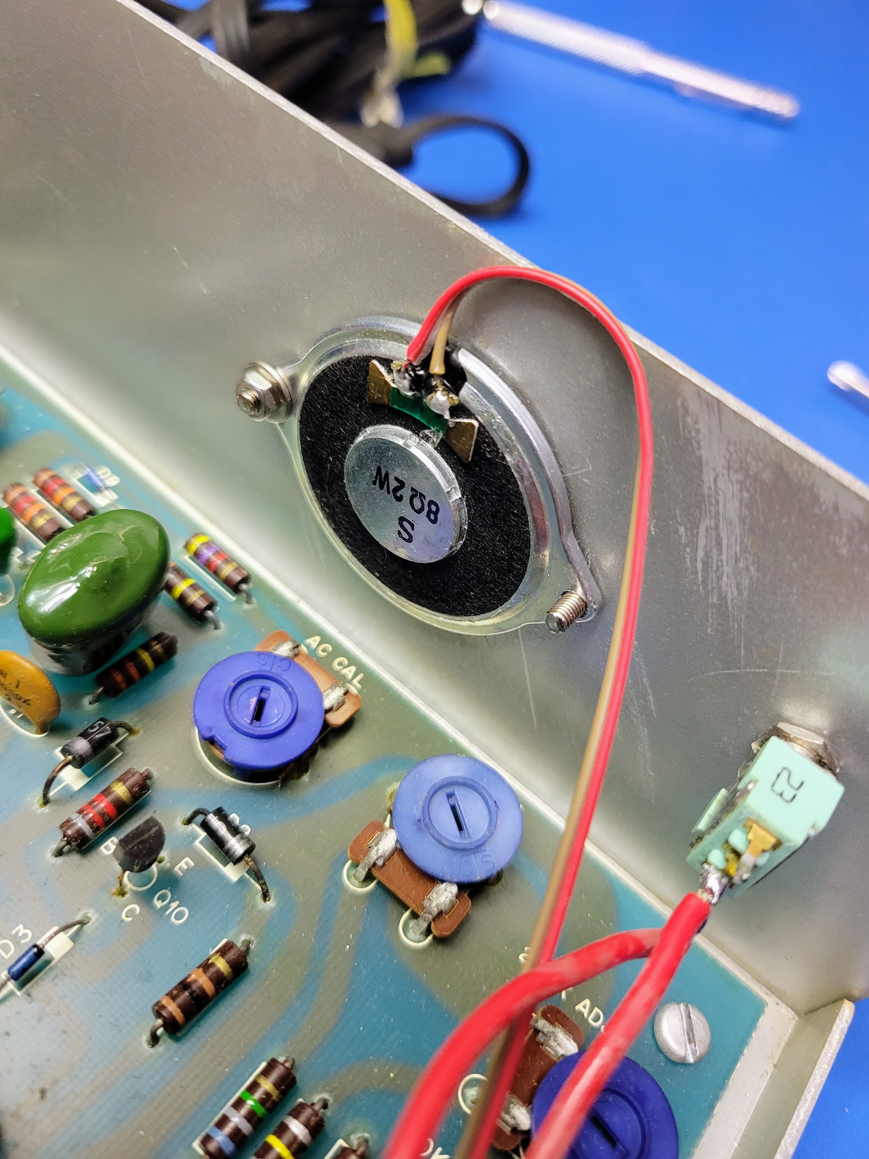
Once mounted, it should look something like this from the outside of the case.
![]()
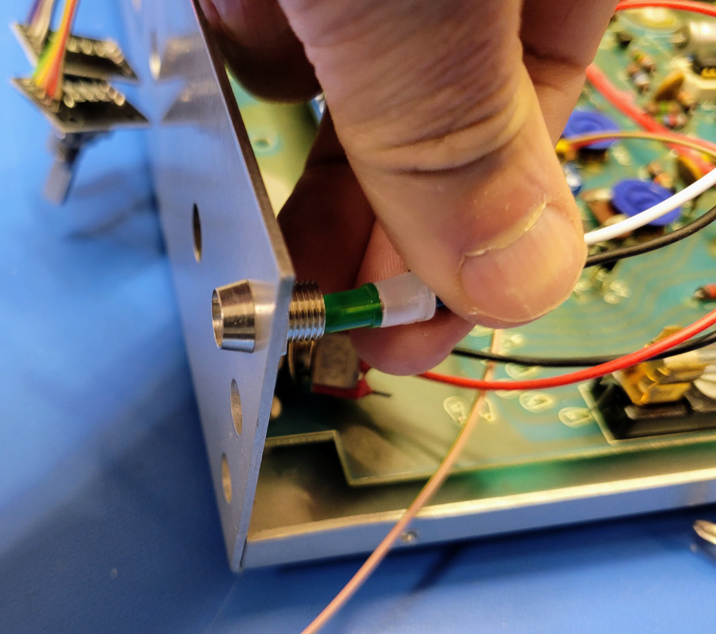
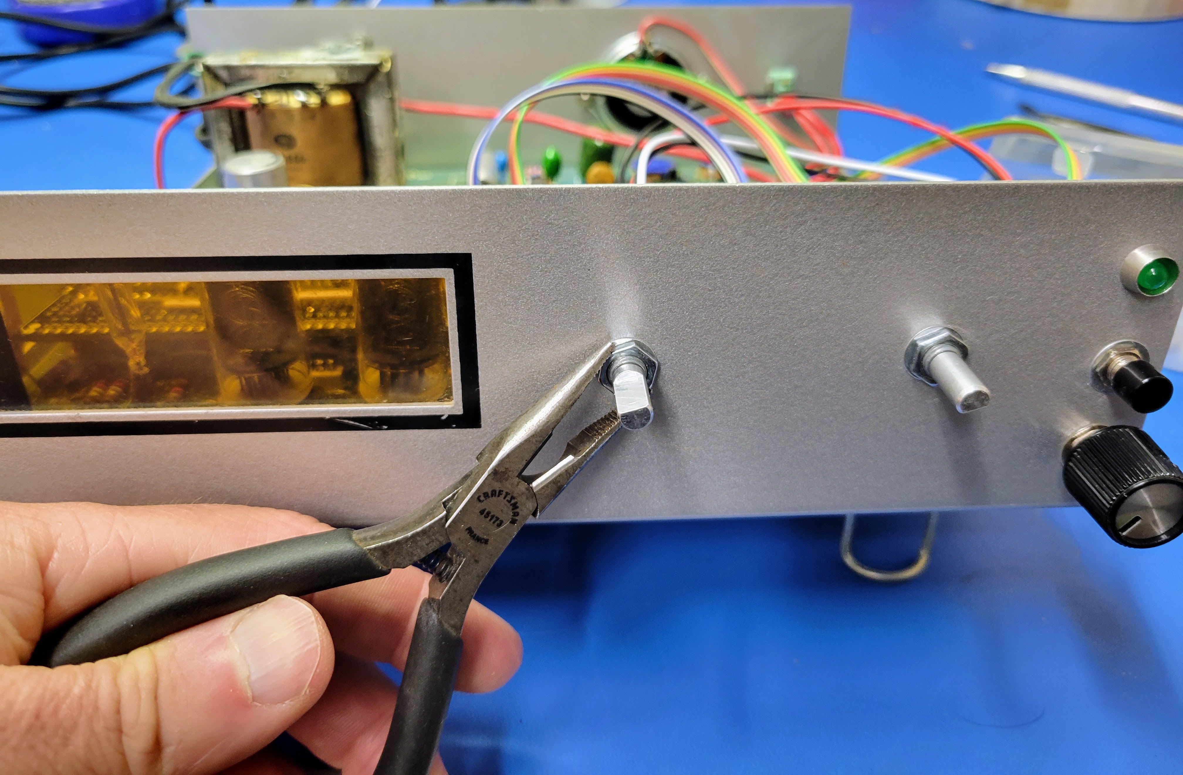
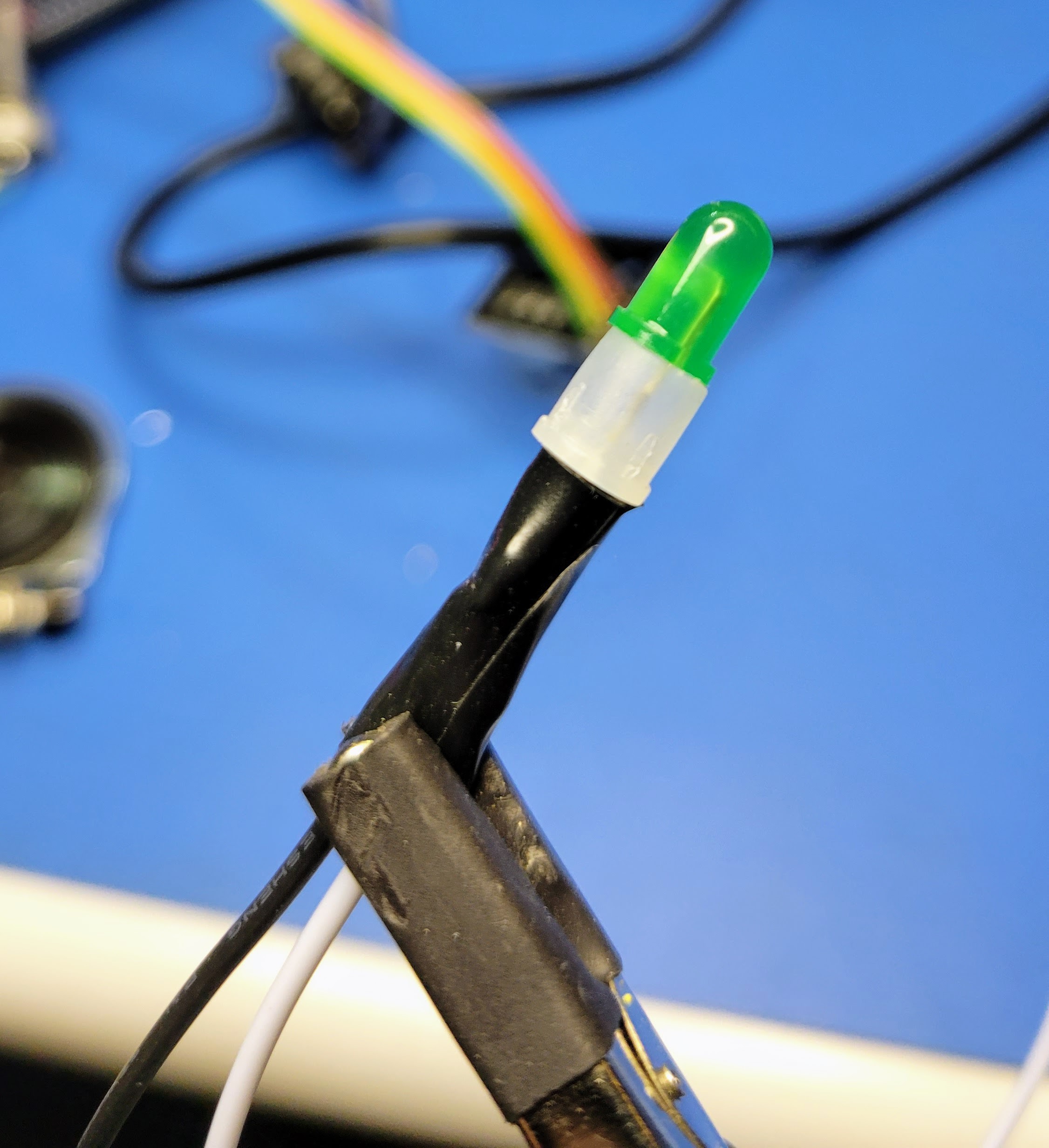
Next put the panel mount LED holder in the front panel and tighten it with the needle nose pliers.
![]()
The LED press into the holder from the back.
![]()
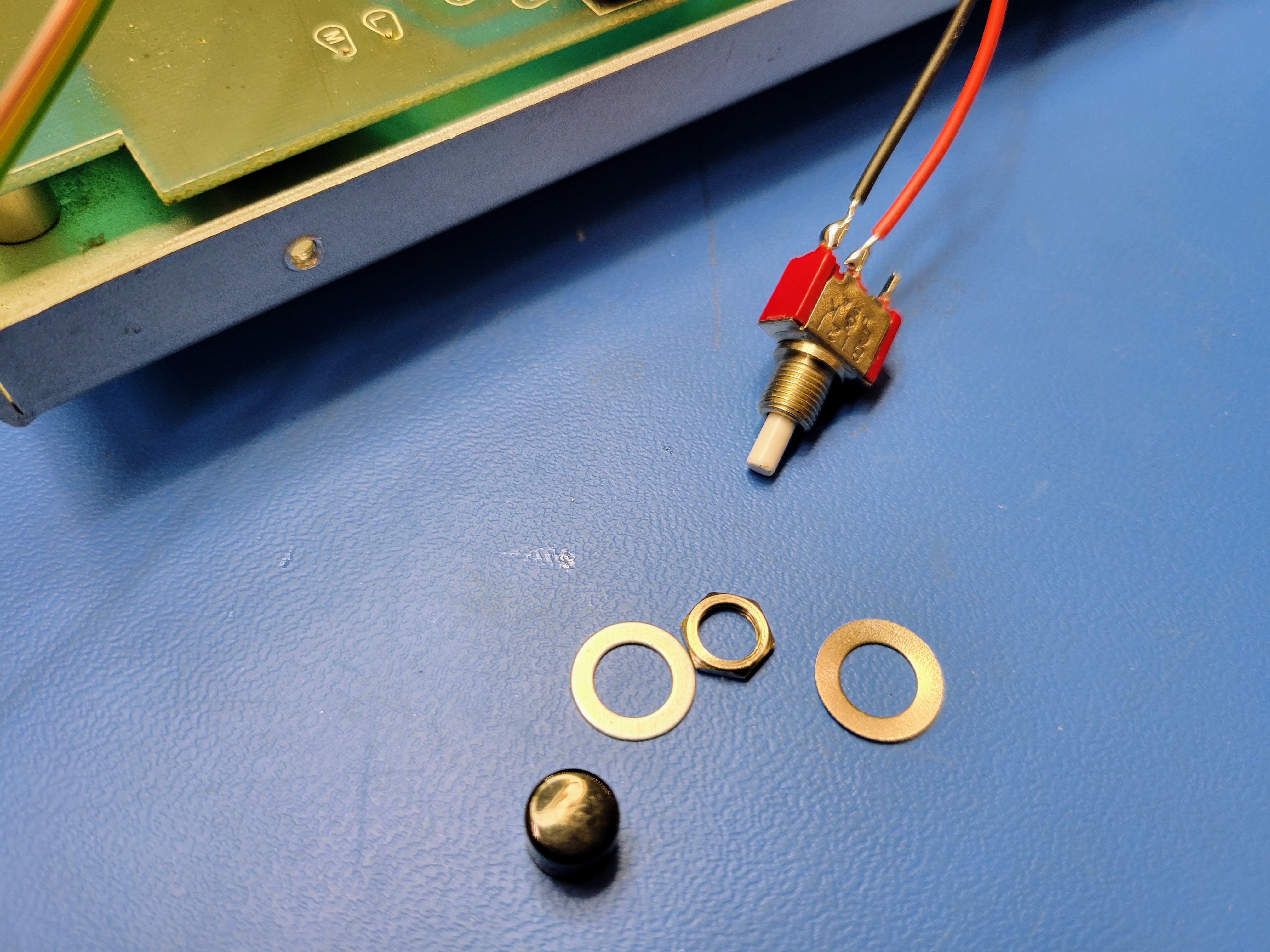
Then select some washers to space the roll button properly.
![]()
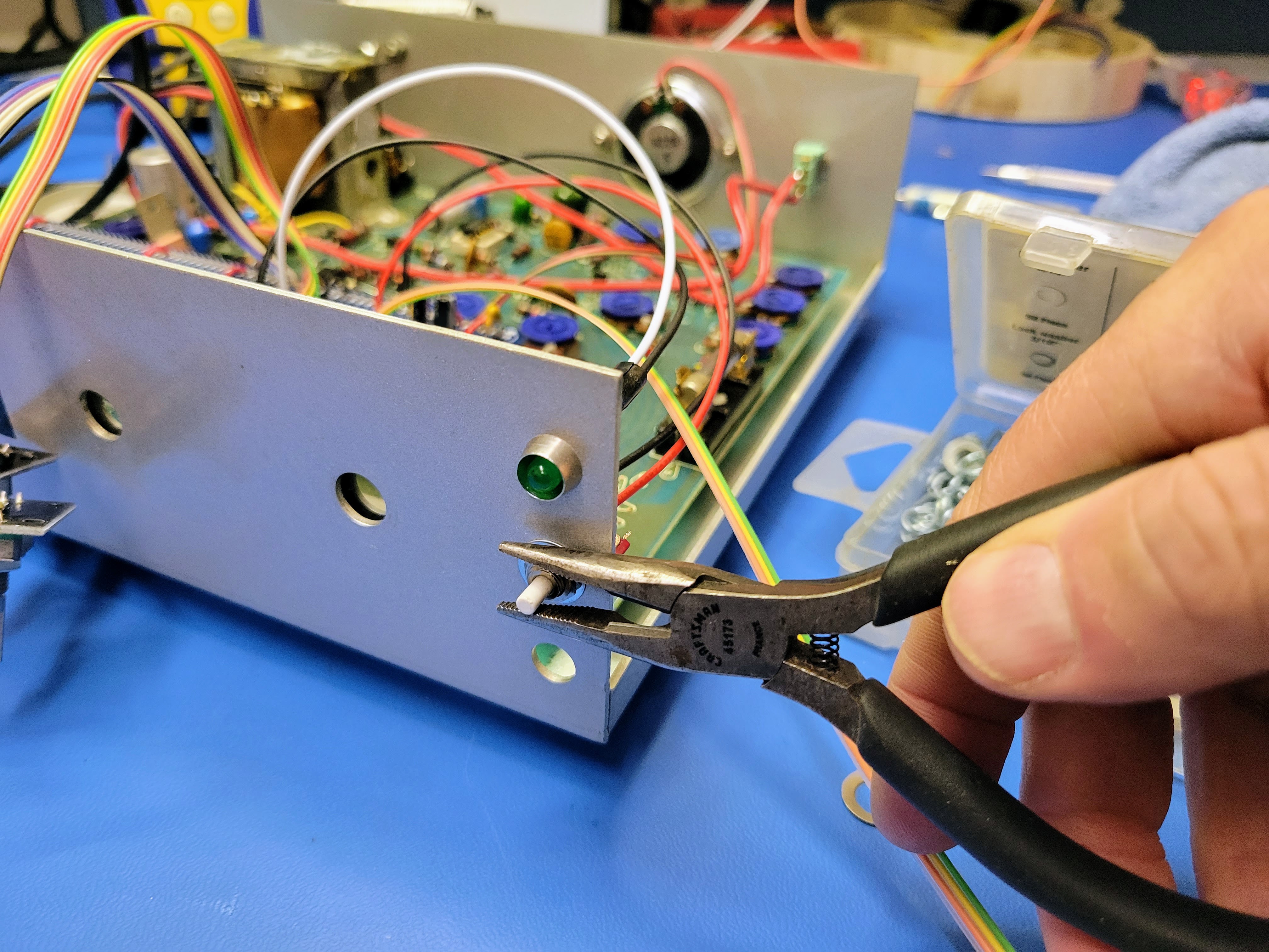
Then insert it into the front panel and tighten.
![]()
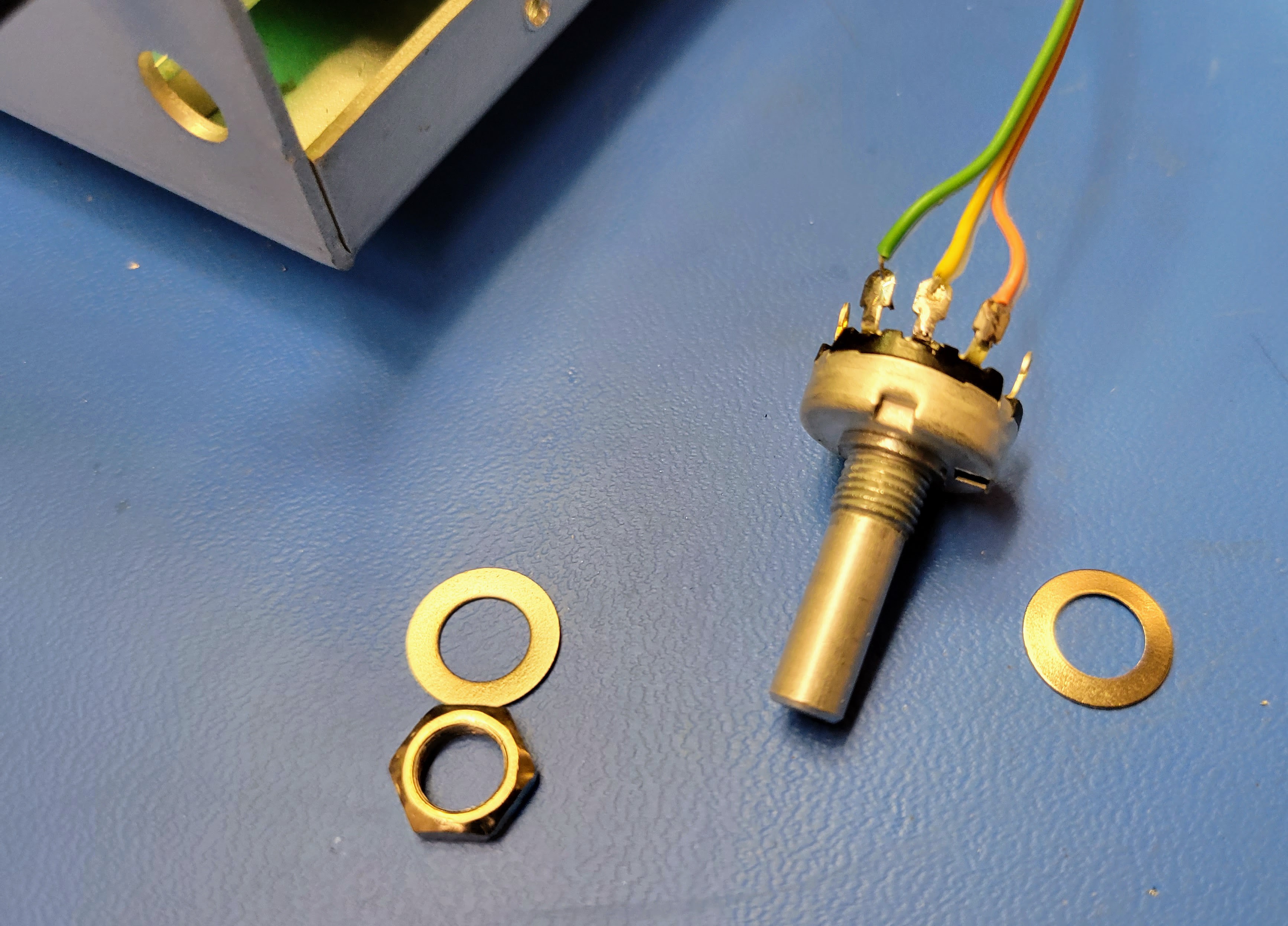
Next select the washers to set the volume pot knob appropriately.
![]()
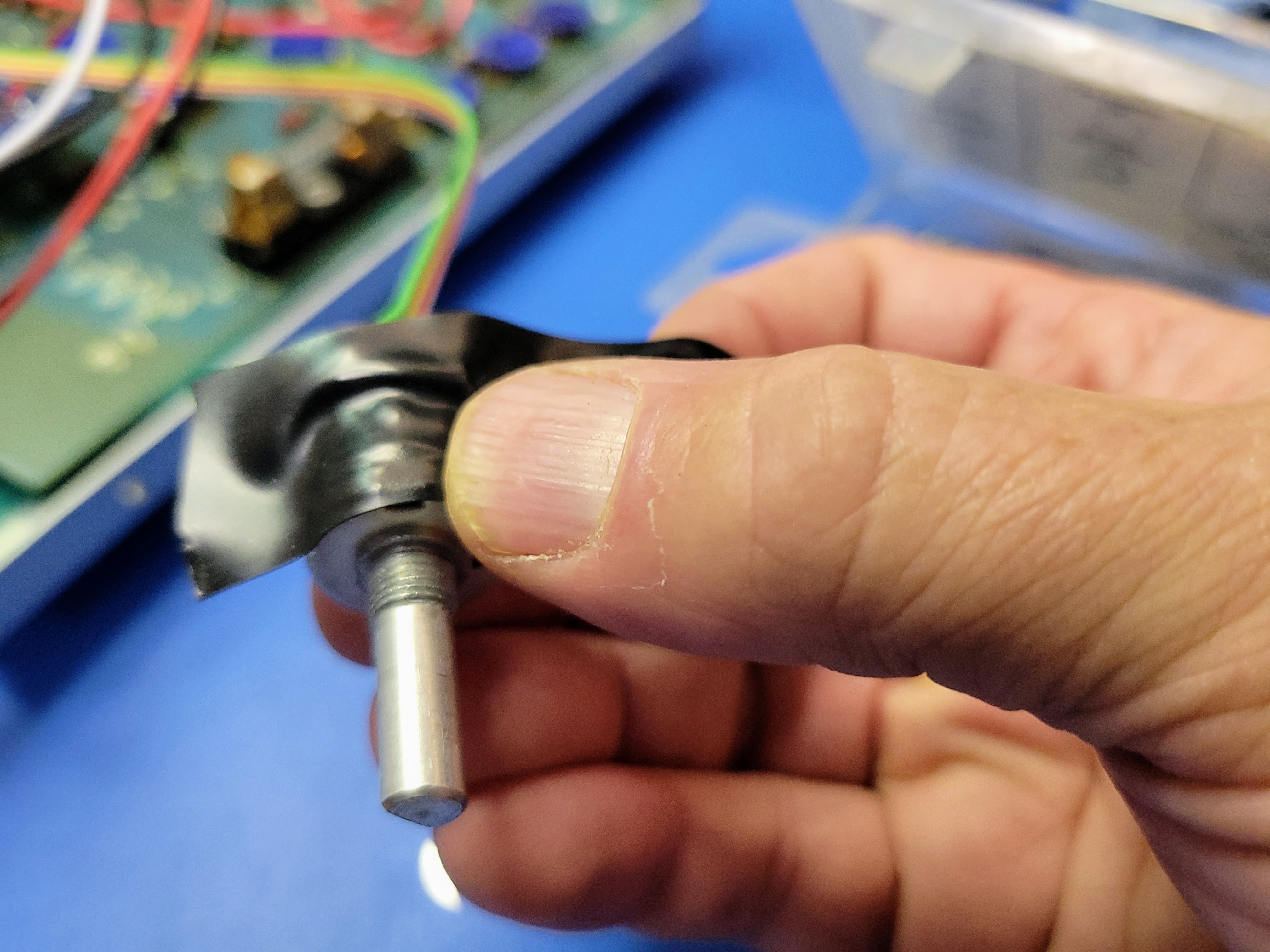
When you mount it, you will need to pay attention to it's orientation. This way low volume is on the left and high volume is on the right according to the knob indicator. Since the lugs will be very close to the metal chassis, I wrap the lugs/body in the single layer of electrical tape.
![]()
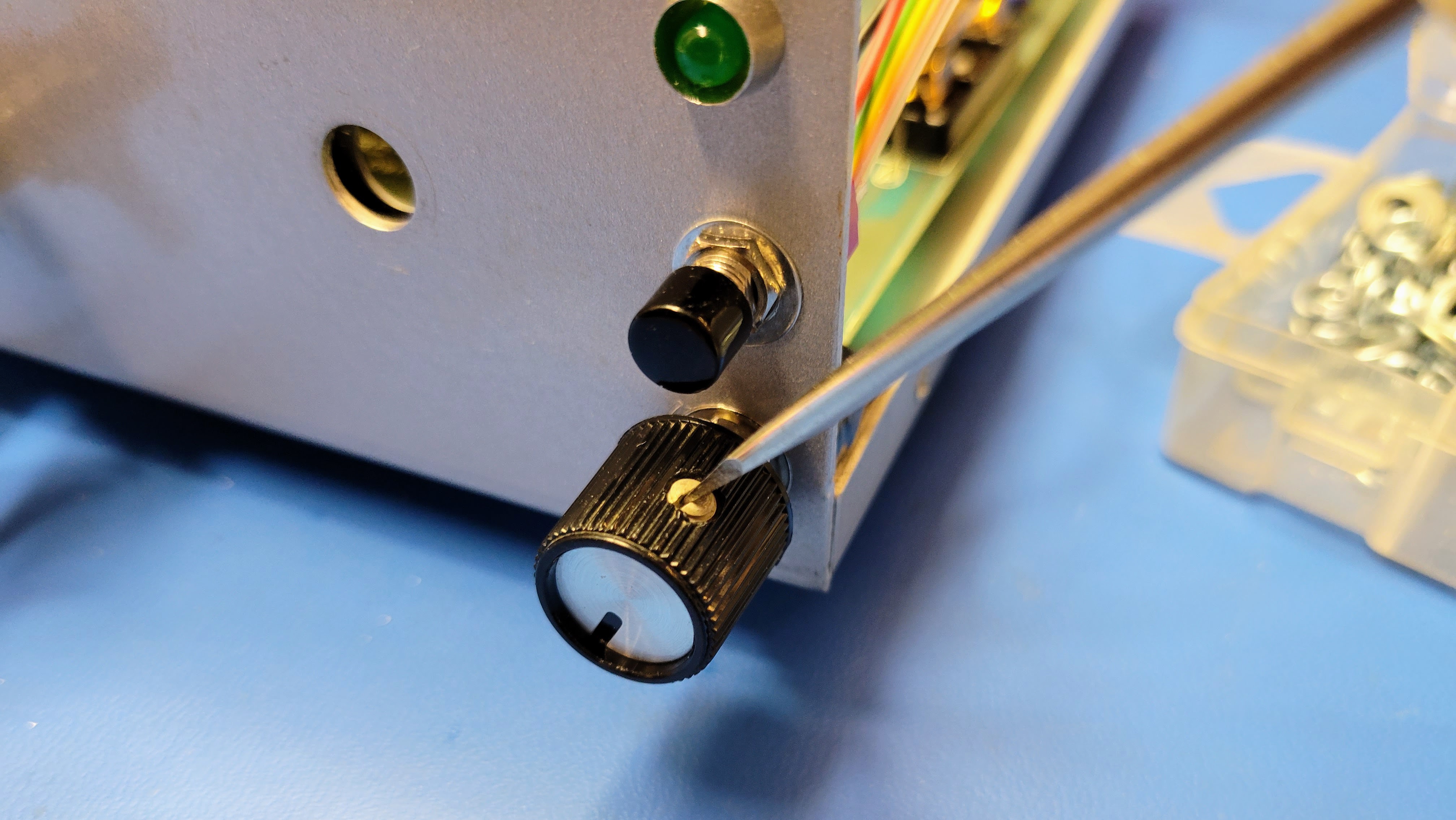
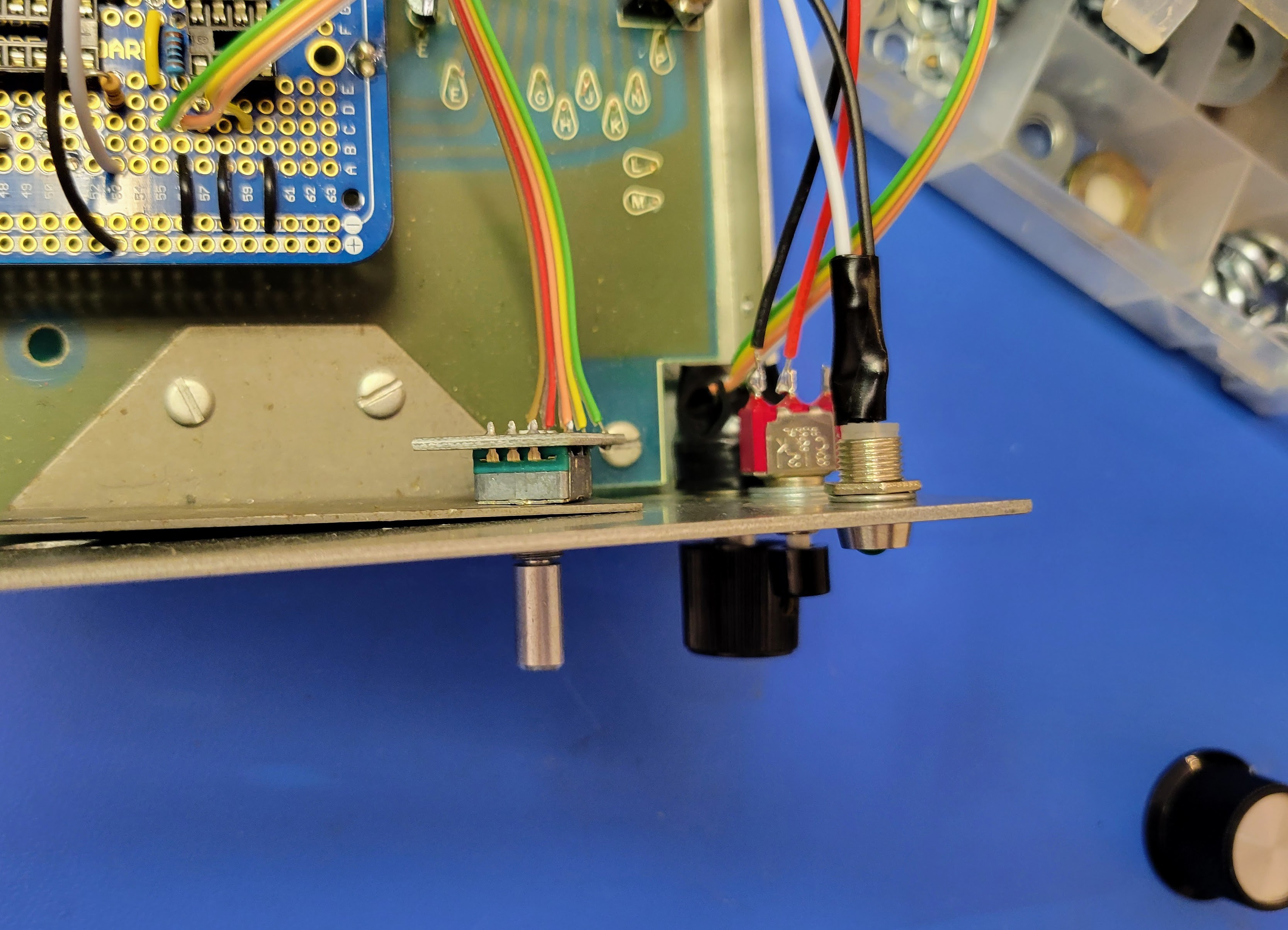
Insert the potentiometer into the front panel, double check it's orientation, tighten, and mount the knob. In this case, the knob has a flat head set screw.
![]()
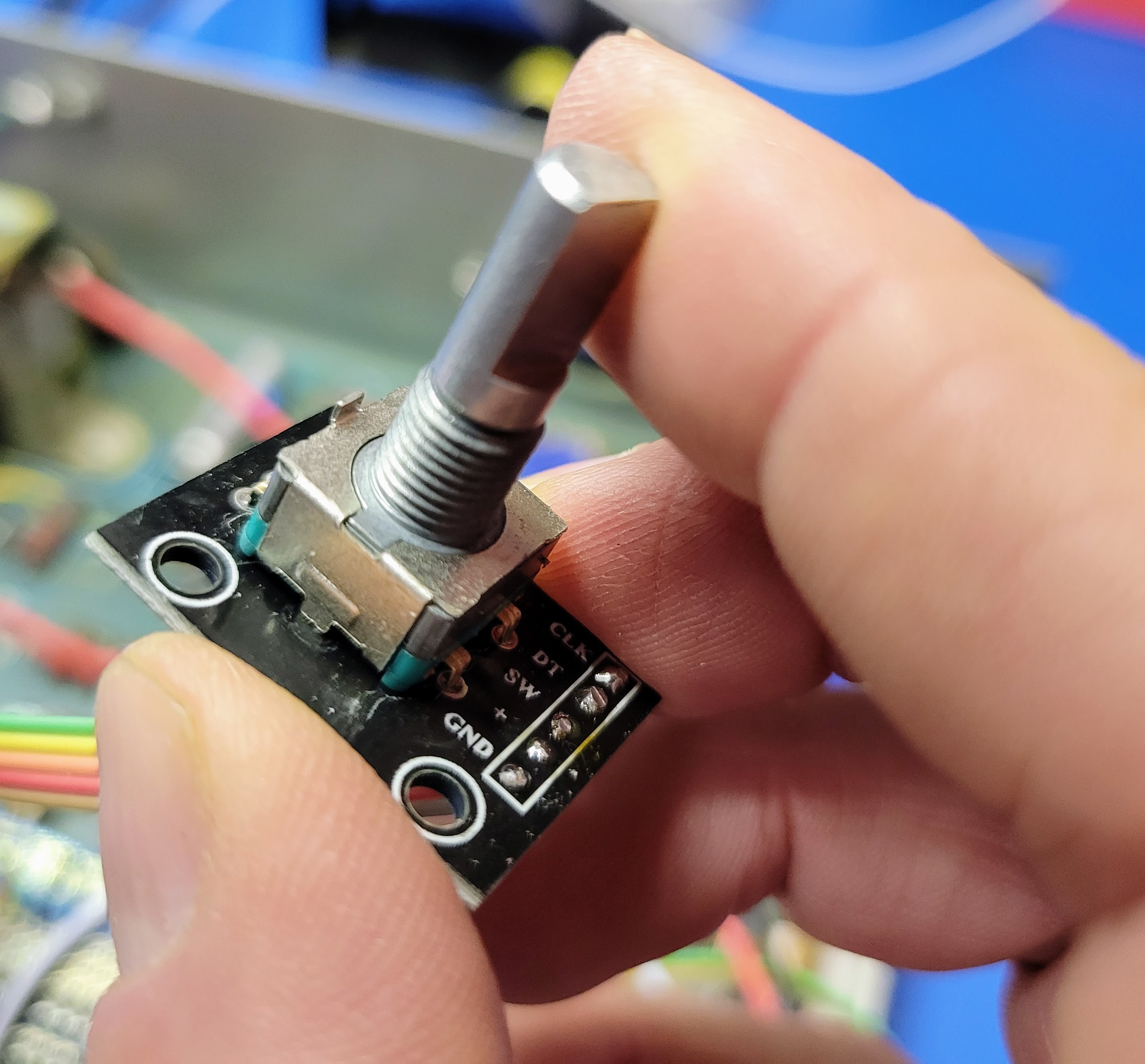
Then check out the rotary encoders. They often have a tab the keeps them from spinning in the panel. I just bend this tab back with a pair of, you guessed it, needle nose pliers.
![]()
The encoders insert through the angle bracket that's screwed to the PCB. This holds everything square. To be honest, it's a little overkill for these encoders. The torque required to turn them is far less than the original rotary switched. So, it's an option to remove the angle bracket if it troublesome.
![]()
If you use the bracket, no washers are required on the back side to space the knob appropriately. Tighten up the encoders with my favorite tool.
![]()
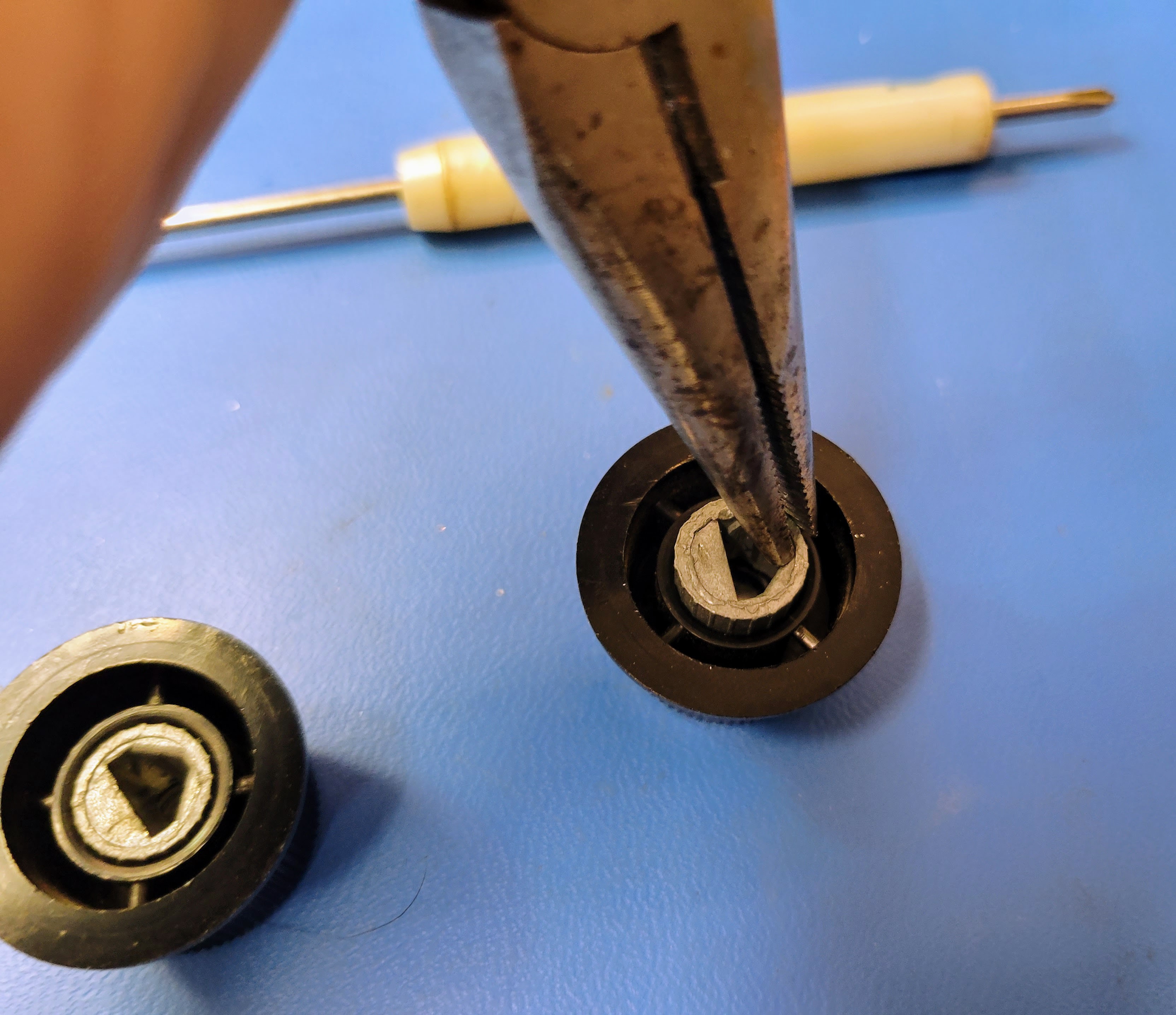
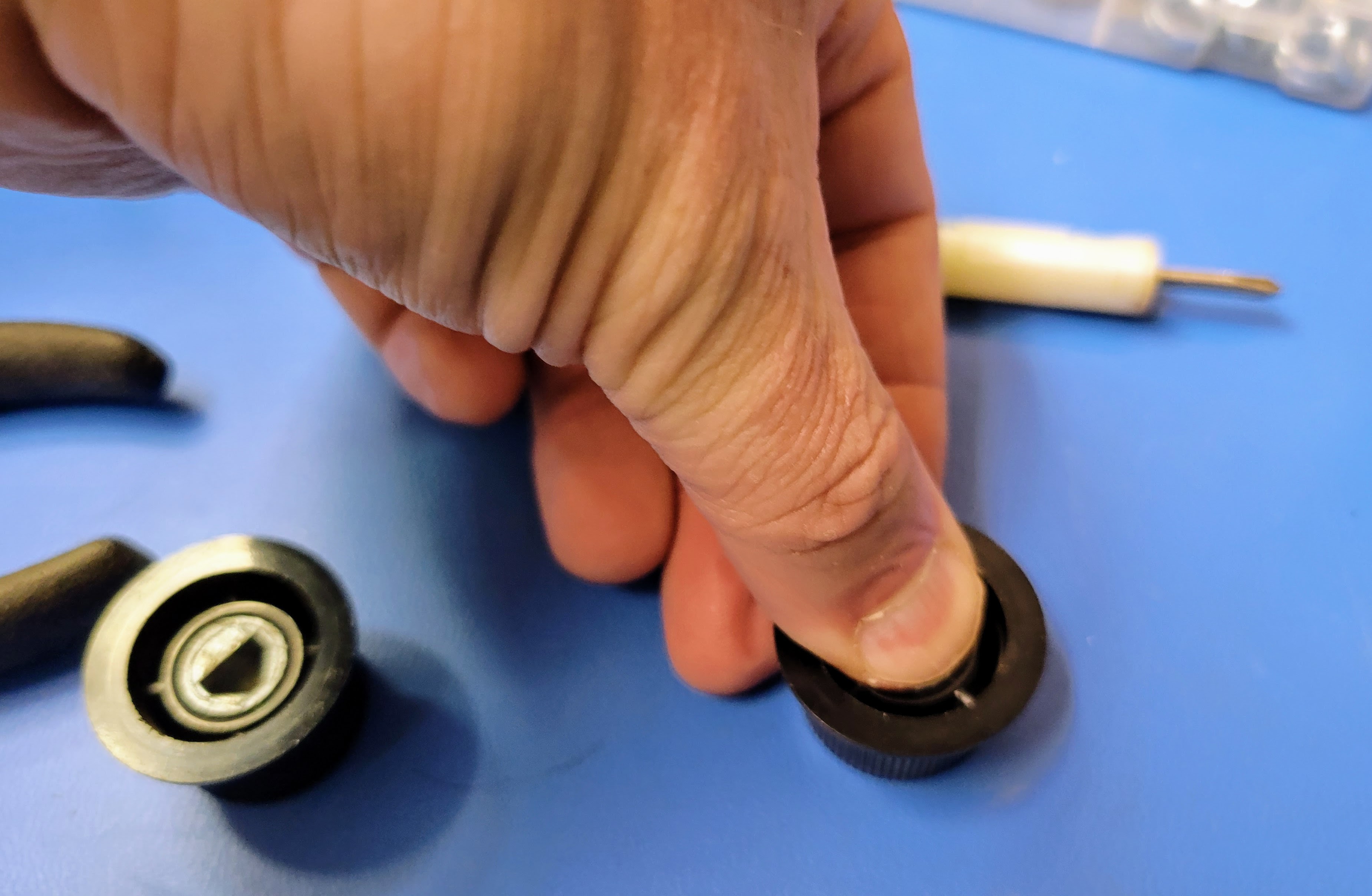
I like to use a variety of knobs on my builds. In this build, I reused the original knobs from the rotary switches. They don't have set screws. They have an interference fit instead. To create this fit, they have a thin piece of spring steel wedged into the pot metal inserts. Using a small screw driver, you can pry the spring steel up and grab it with the trusty needle nose pliers. With a little effort, you can pull it out. Frequently, the pot metal insert will pull out of the knob while doing this. Once the spring steel is out, you can simply press the pot metal insert back into the knob with your thumb.
![]()
![]()
Since there is no set screw, the knobs will have a loose fit. A single drop of super glue is enough to hold them in place. However, I suggest doing that very last after you have proven that everything is working the MCU programmed and in place. We'll do that in the next blog. At this point, your face plate should look something like this.
![]()
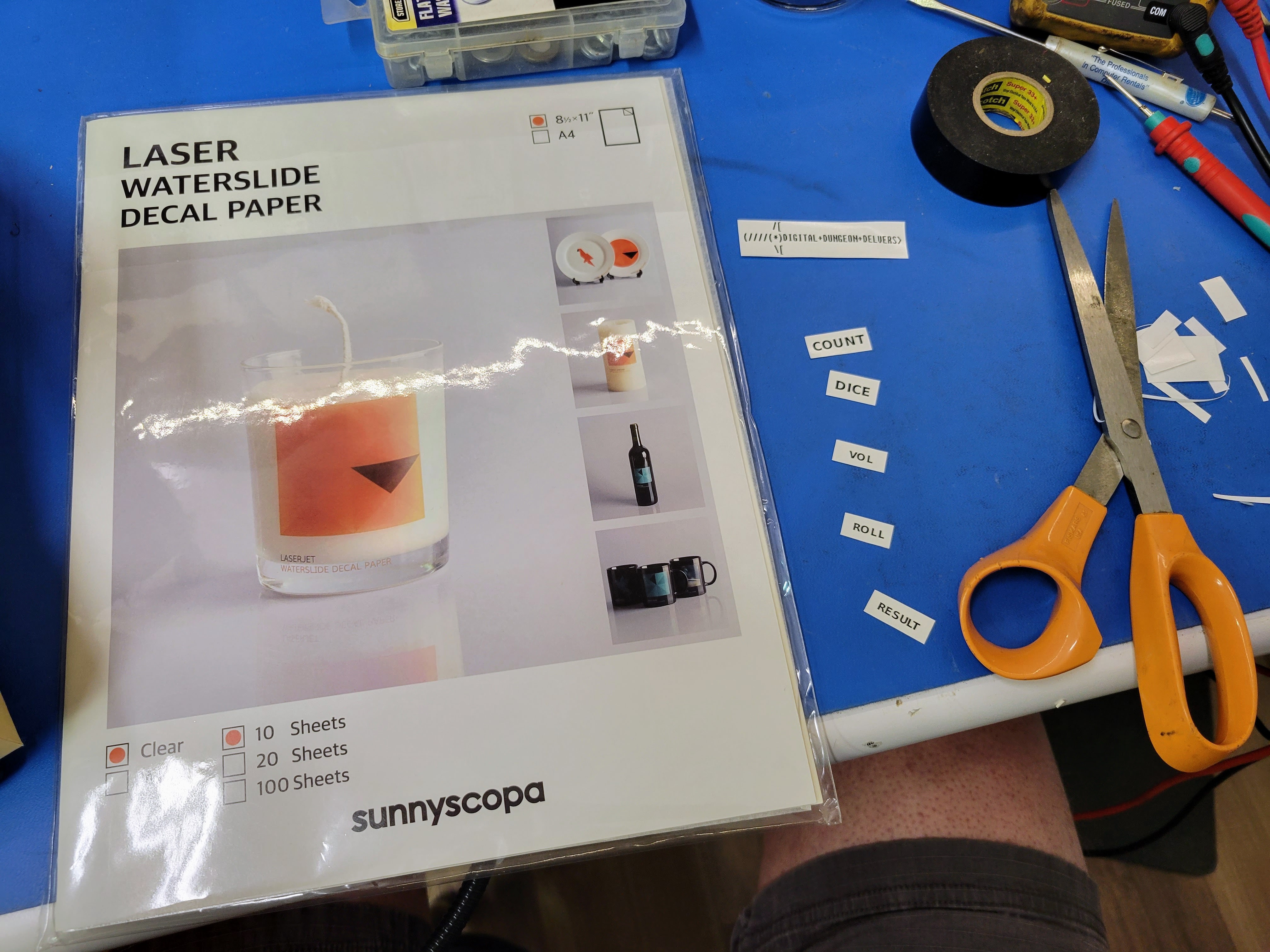
For this build I am going with graphics that appear silk screened to the face plate like the original graphics. To get this effect without a lot of effort, I like you use laser printer compatible water slide decals. Just design the graphics you want your PC, print them on the water slide "paper", and put them on the face plate. I have been using these water slide decal papers. They seem to work reasonably.
![]()
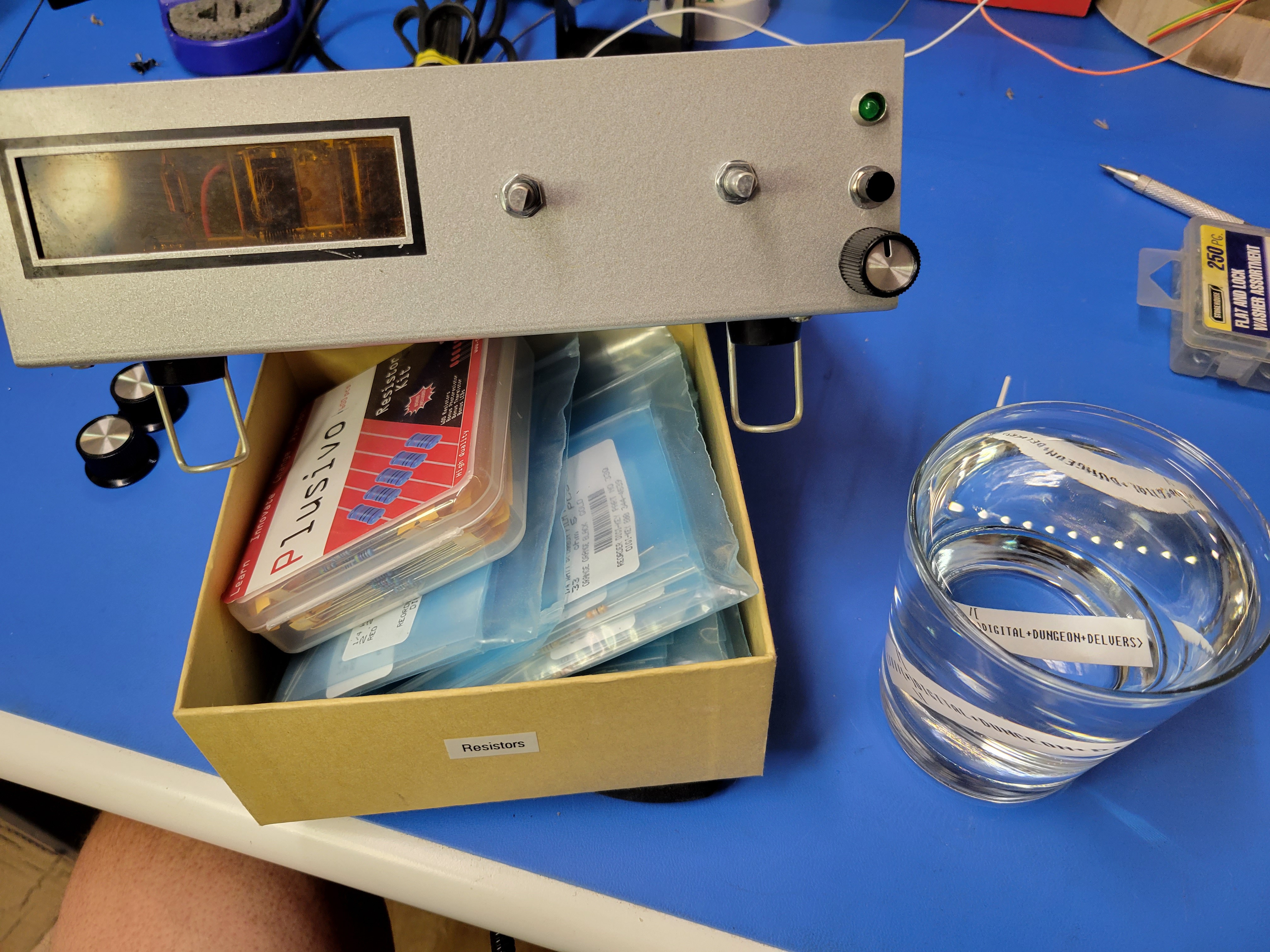
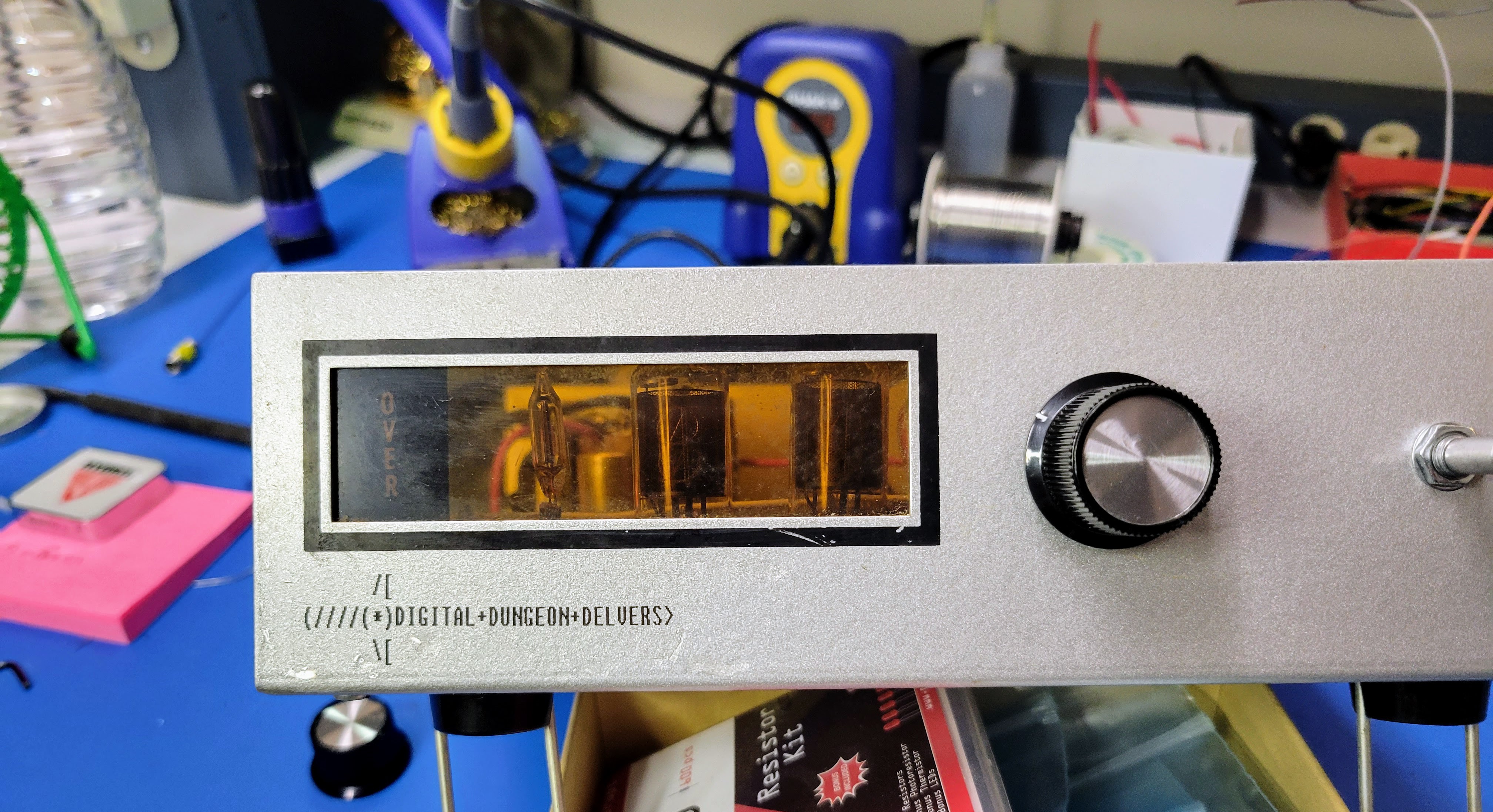
Print out the graphics and cut them out. Then, soak them one at a time in warm water for exactly 30 seconds. I say that because if you soak them any longer the decal will come off the paper backing before you pull it from the water. Pull the paper with the decal from the water and slide the decal off the paper (or the paper out from under the decal) as you hold it against the face plate. Once the backing paper is out, you can very gently slide the graphic around. Try to minimize this. It's possible to fold over or rip the graphic if you work it too much. Also, I have found it easier to put the decals on with the knobs off. However, you'll want to put the knobs on temporarily to determine where to place the graphics. If you didn't place water slide decals on your plastic models (cars and planes), I suggest looking up some YouTube videos demonstrating how to best place water slide decals.
![]()
![]()
Let the decals dry overnight.
At this point, your device should be looking something like this. It's now ready for the MCU. We'll program that and insert it in the next blog.
![]()
-
Build the Controller (Part 3)
08/30/2022 at 04:57 • 0 commentsNext we'll connect the volume potentiometer, rotary encoders, button, LED, and speaker to the controller board.
![]()
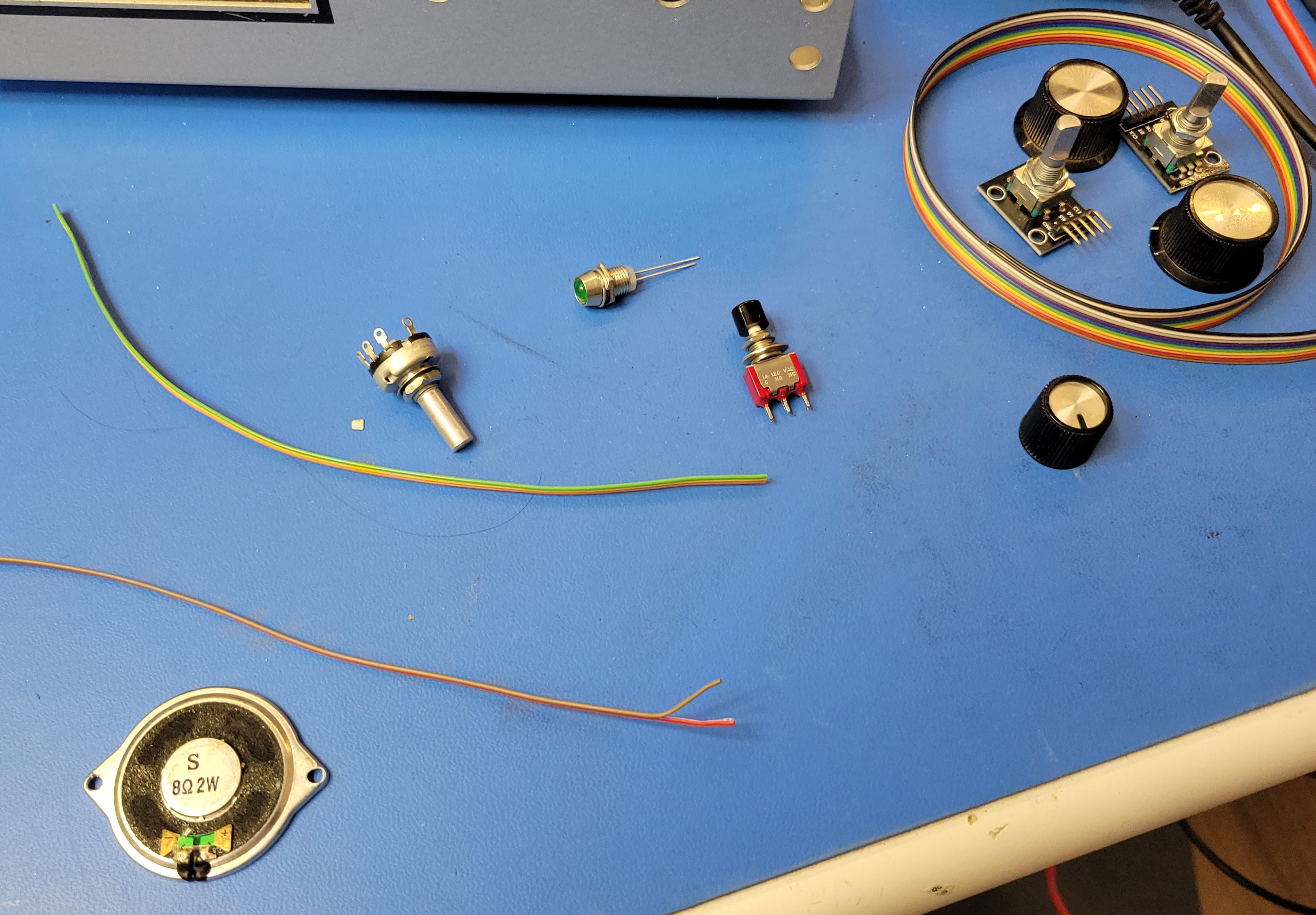
Start with an 0hm speaker and a small 10K potentiometer with appropriate lengths of 28 awg stranded ribbon cable wire. You'll need two conductors for the speaker and 3 conductors for the volume potentiometer. I have a stash of 10 conductor ribbon cable I pull these from and cut to approximately 8" to 9" length.
![]()
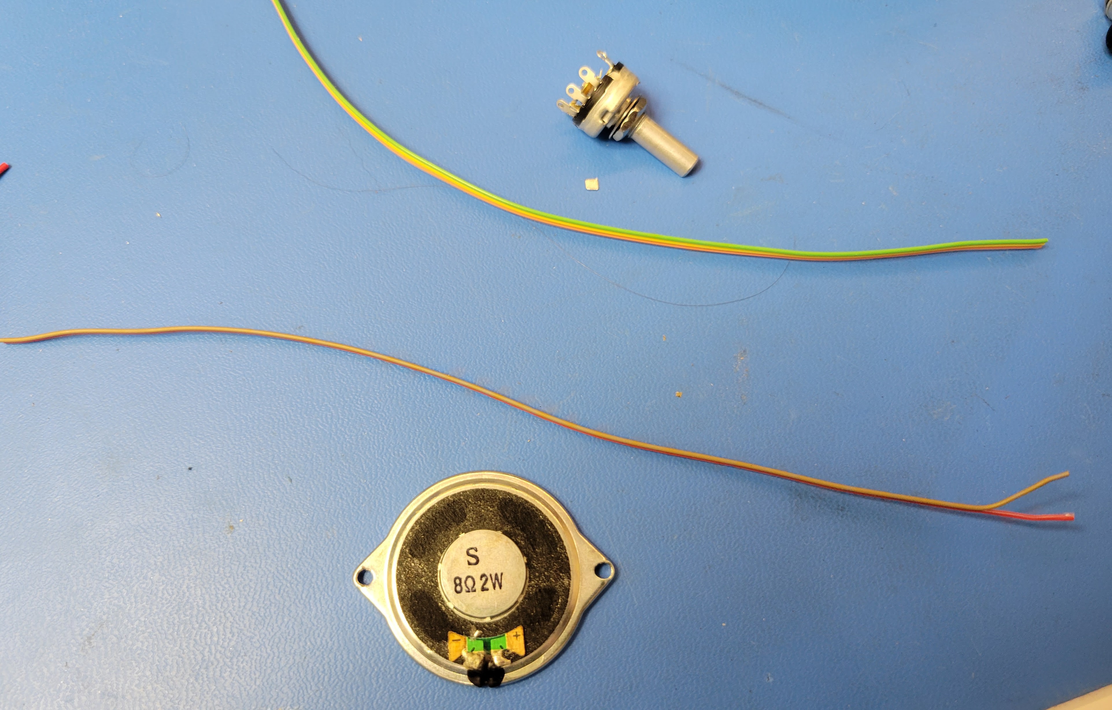
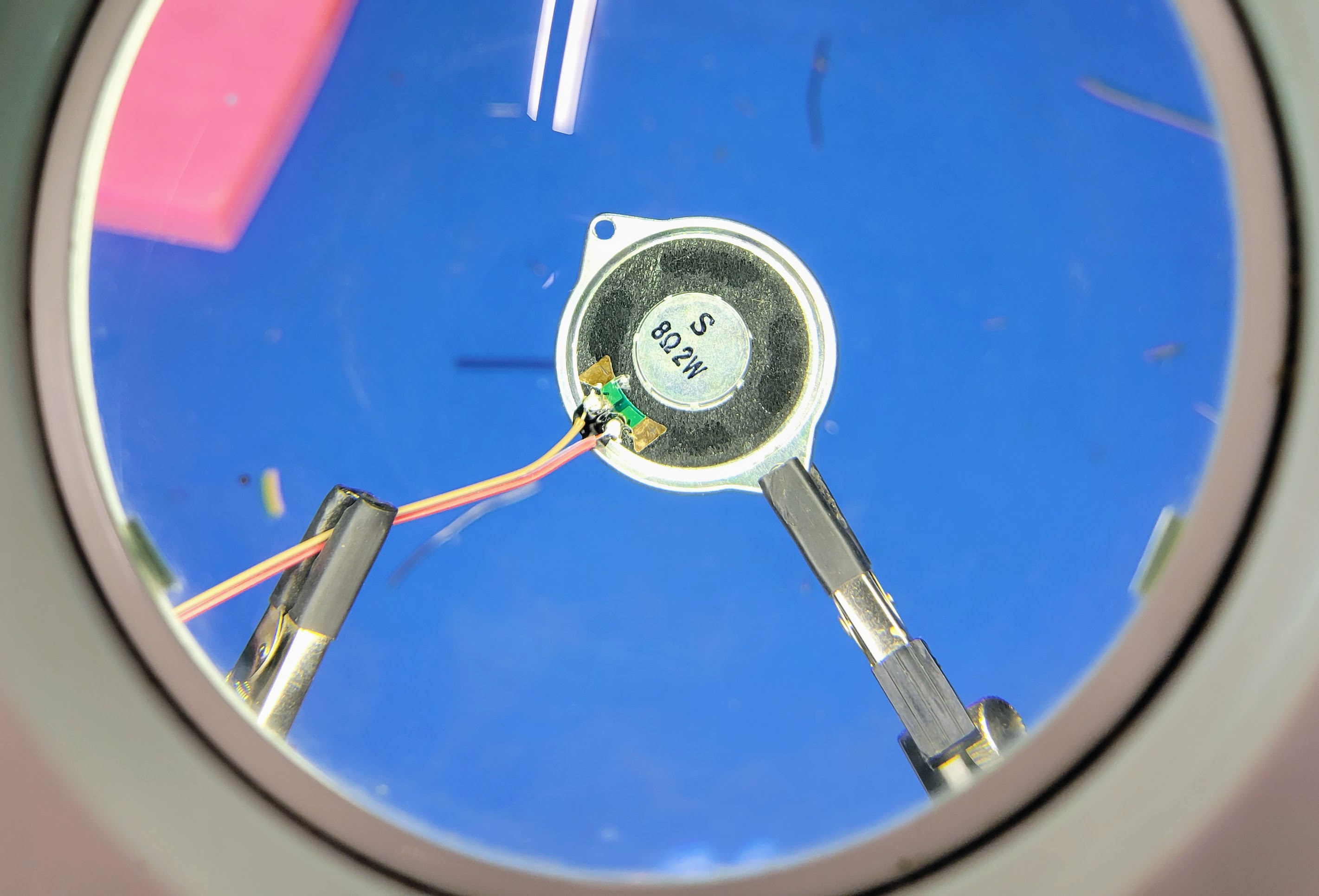
First, solder the tow conductor wire to the speaker.
![]()
Then solder the other end of the speaker wire + to row 62 column J. This is the negative side of the 220 uF filtering cap.
![]()
![]()
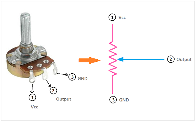
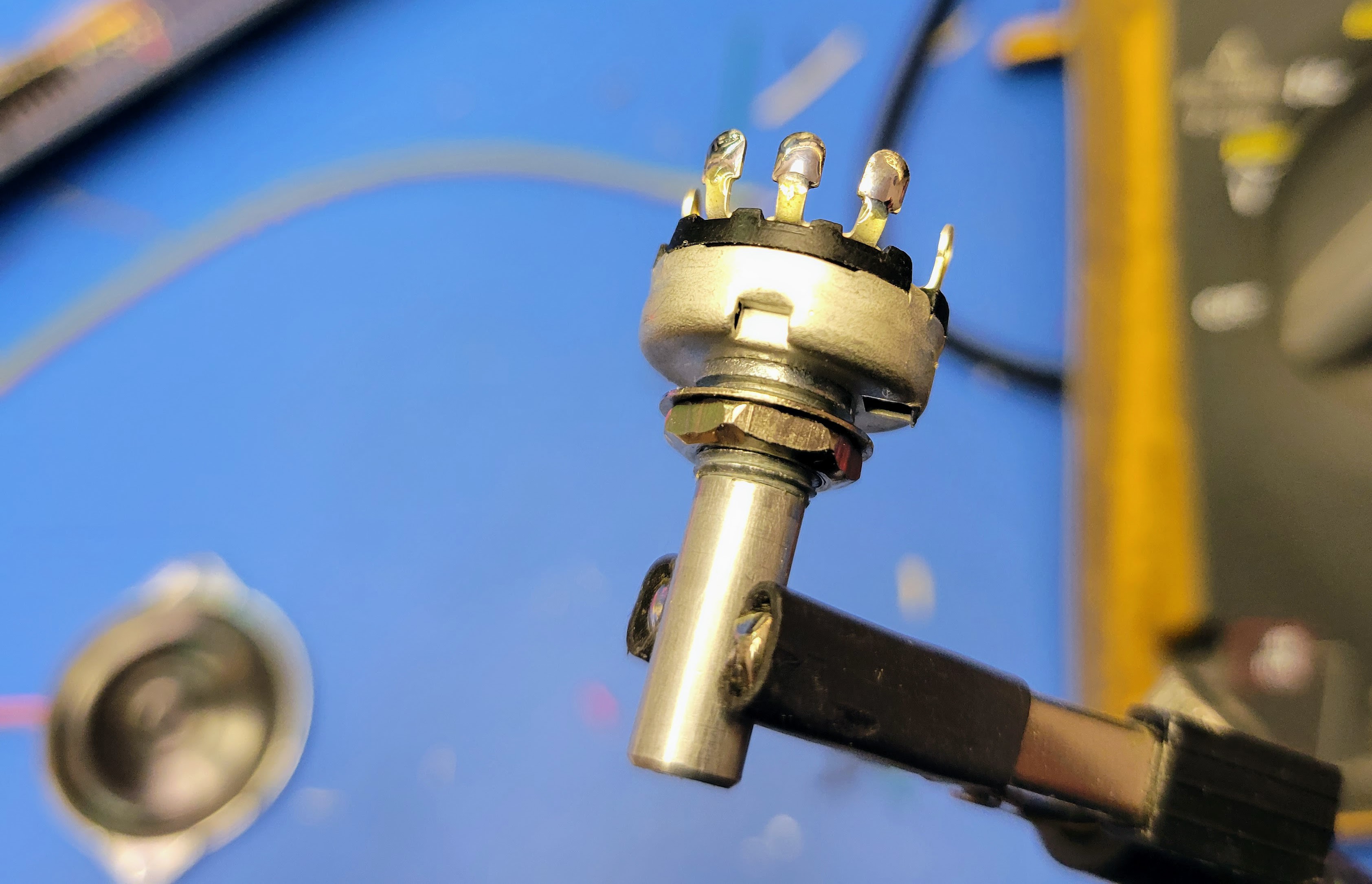
Next solder the three conductor wire to the small (5/8" diameter) 10K potentiometer. Before doing so, confirm which of the leads should be wired to signal input should be wired to ground.
![]()
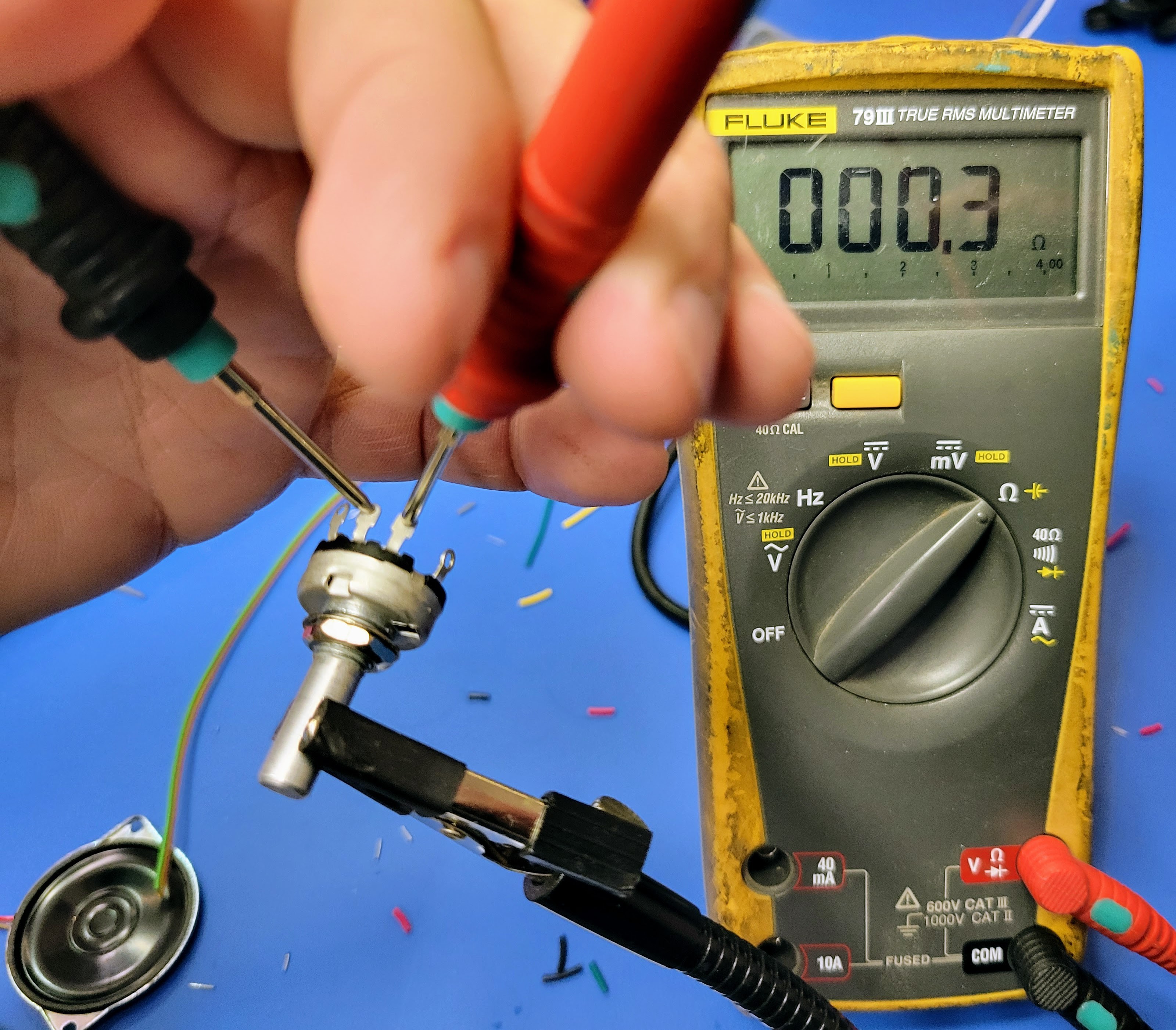
The center lead/lug is the wiper and that will be wired to signal output to the audio amplifier. Turn the shaft all the way to the left (turn the volume down). Then check the resistance between the center lug and each of the other two lugs. Ground will be connected to the lug with near zero resistance and the input will be connect to the lug with near 10K resistance.
![]()
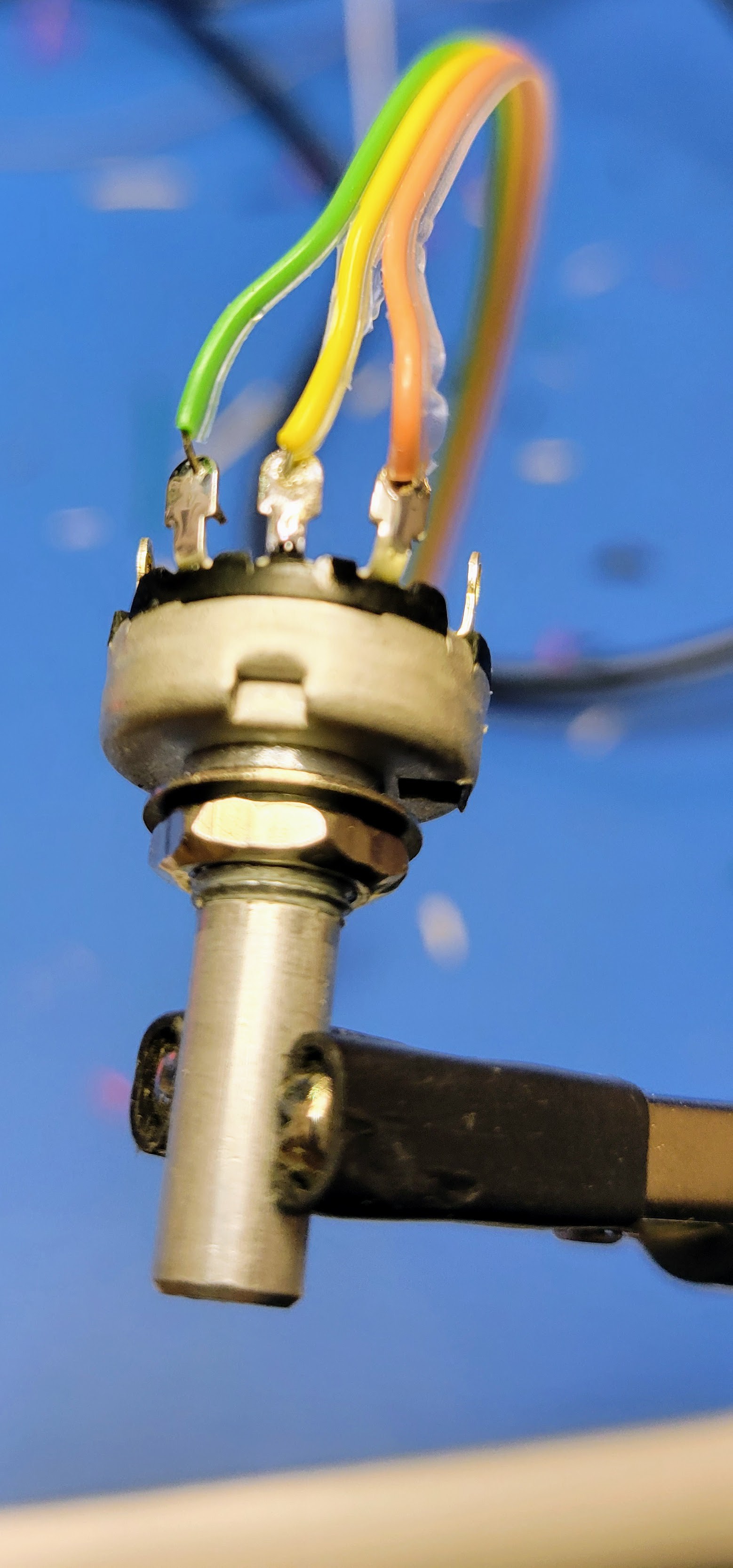
For solder lugs like the ones I have here, it's easiest to blob some solder on the lugs before connecting the wires.
![]()
![]()
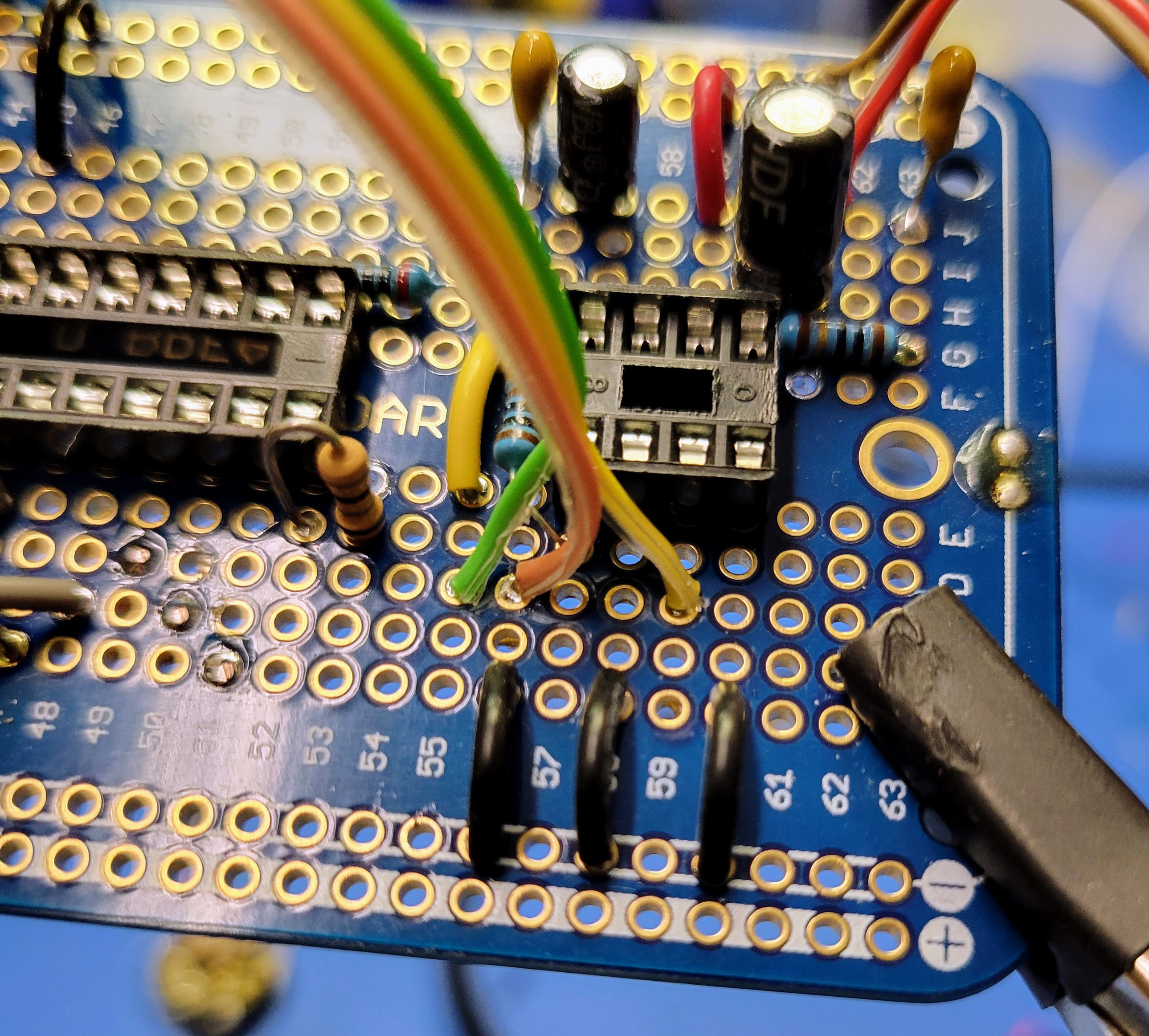
The wires from the potentiometer are then connected to the controller board.
- The ground lead wire is connected to the ground bus
- The input signal lead is connected to the output from the RC filter connected to pin 17 of the microcontroller (row 55 column C)
- The output signal is connected to pin 3 of the audio amplifier (Row 59 Column C)
![]()
Next connect the roll button to the microcontroller. This I/O pin is configured with an internal 10K pull up. So, you can wire the Normally Open leads to directly to pin 15 of the MCU (Row 52 Column J) and the ground bus.
![]()
![]()
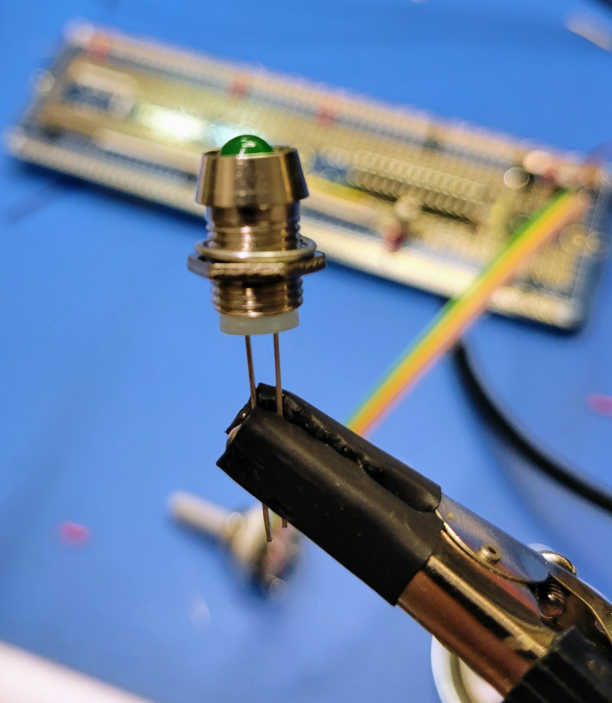
Next wire the result indicator LED to the current limiting resistor (pin 14 on the MCU) installed in a previous log and ground. The positive lead of the LED (the longer lead) will connect to row 53 column A. The negative lead connects to the ground bus.
![]()
![]()
![]()
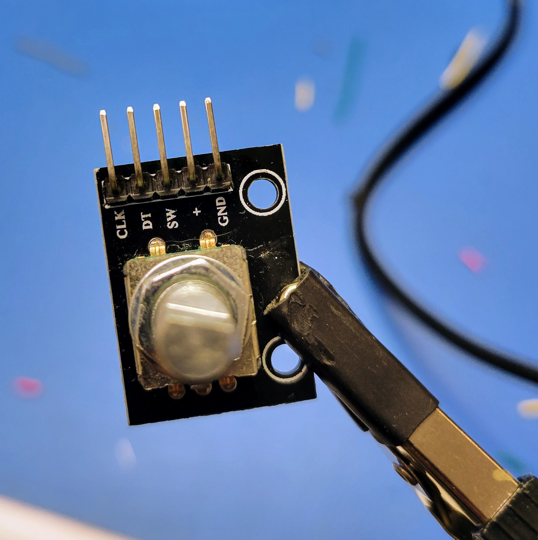
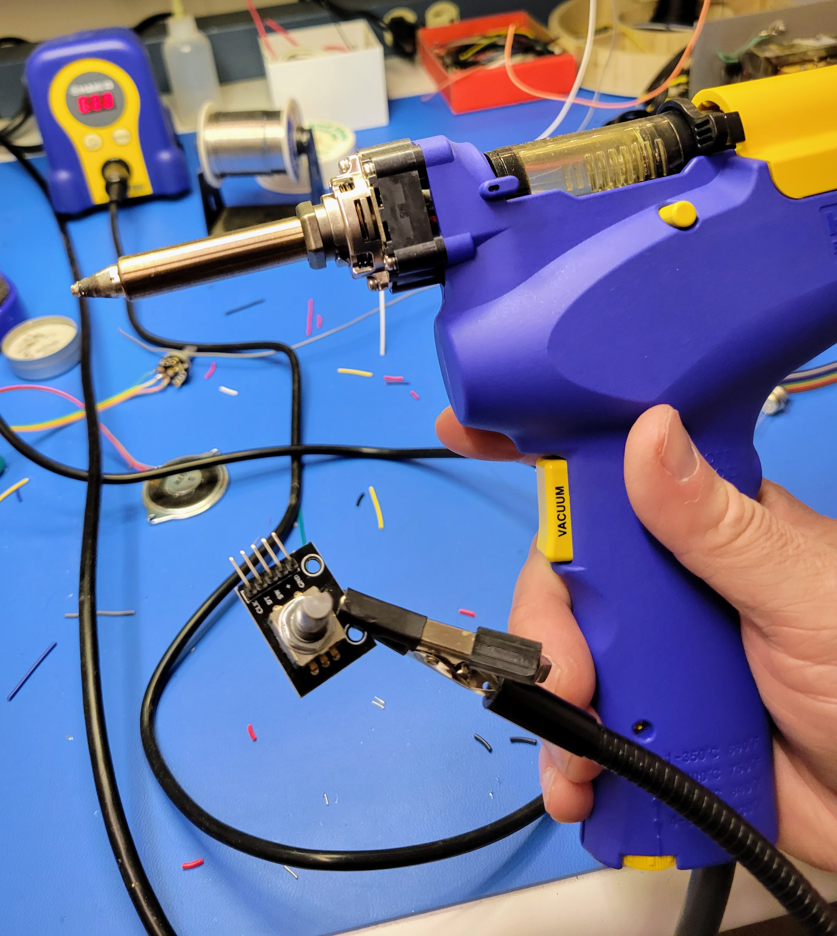
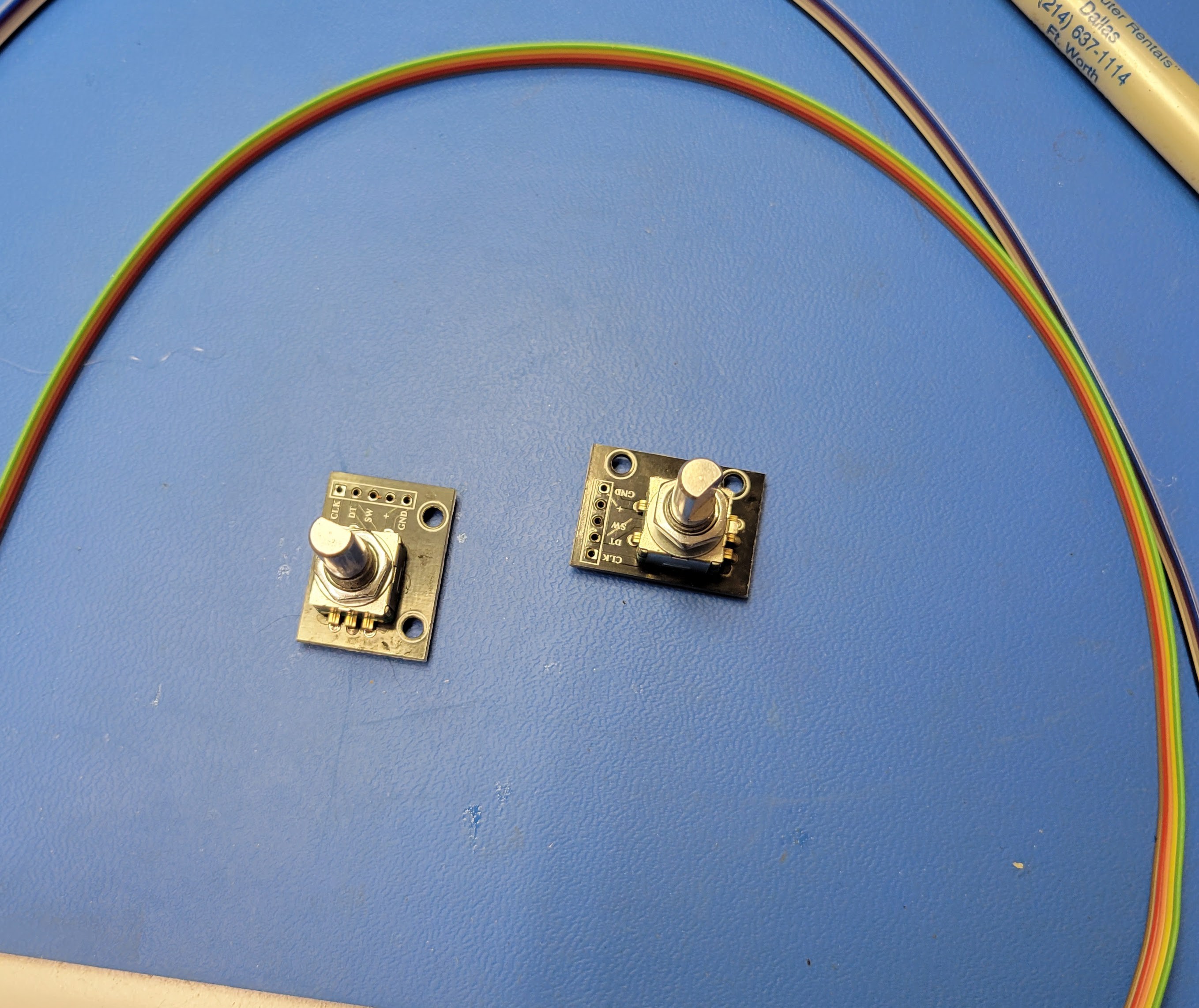
Finally connect the two rotary encoders to the MCU. These will be connected directly to +5v bus, ground bus, and 3 I/O pins. The rotary encoders that I purchase come with inline 5 pin IDC connectors. However, I find it easier to remove this connector with my handing solder sucker and wire the 5 conductor ribbon cable directly to the board.
![]()
![]()
![]()
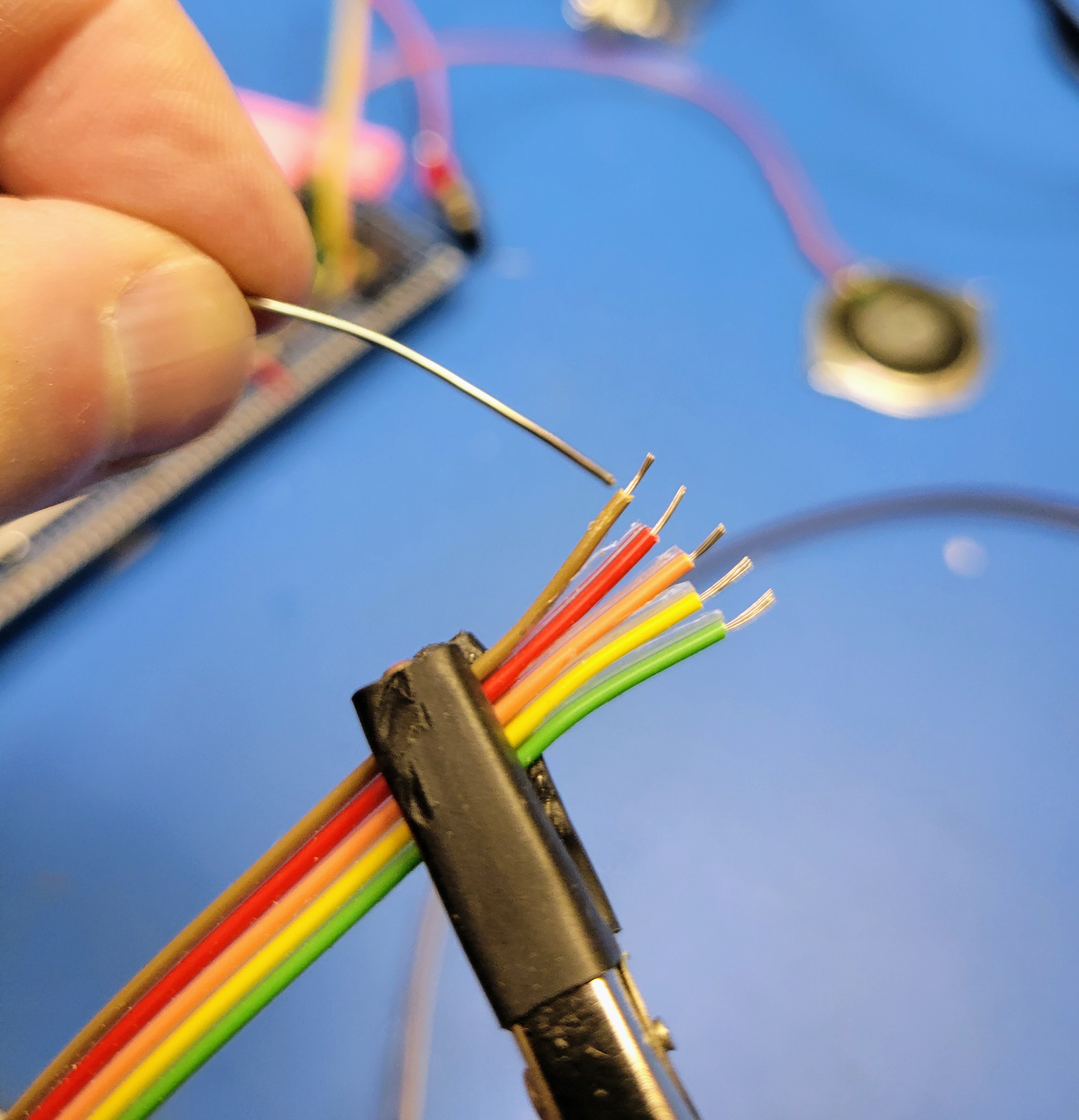
As with other stranded wire, I find it much easier to tin the wire before soldering to the board.
![]()
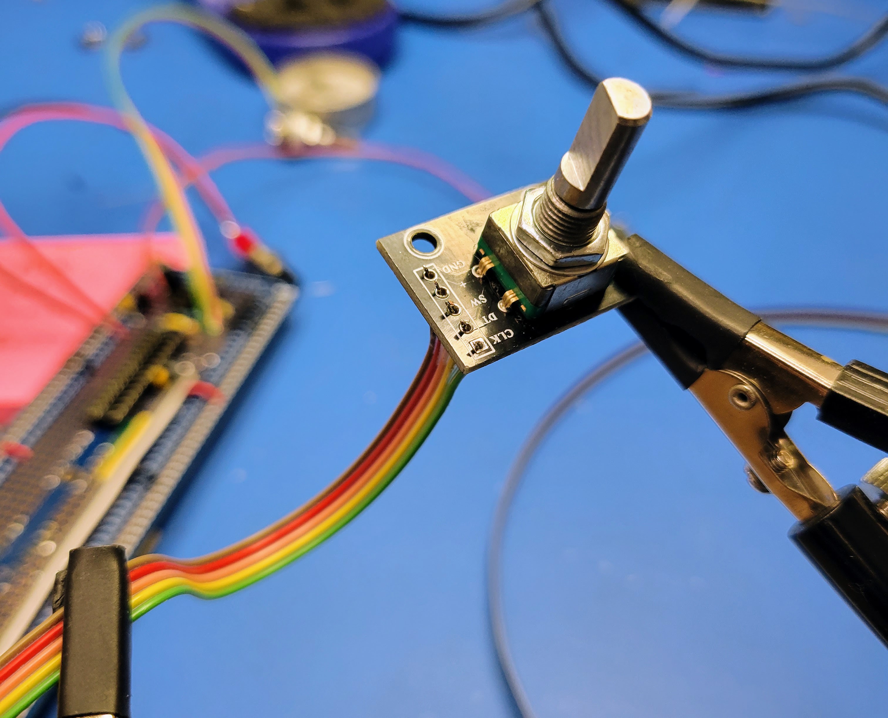
The ribbon cable wired to the encoder board will look something like this.
![]()
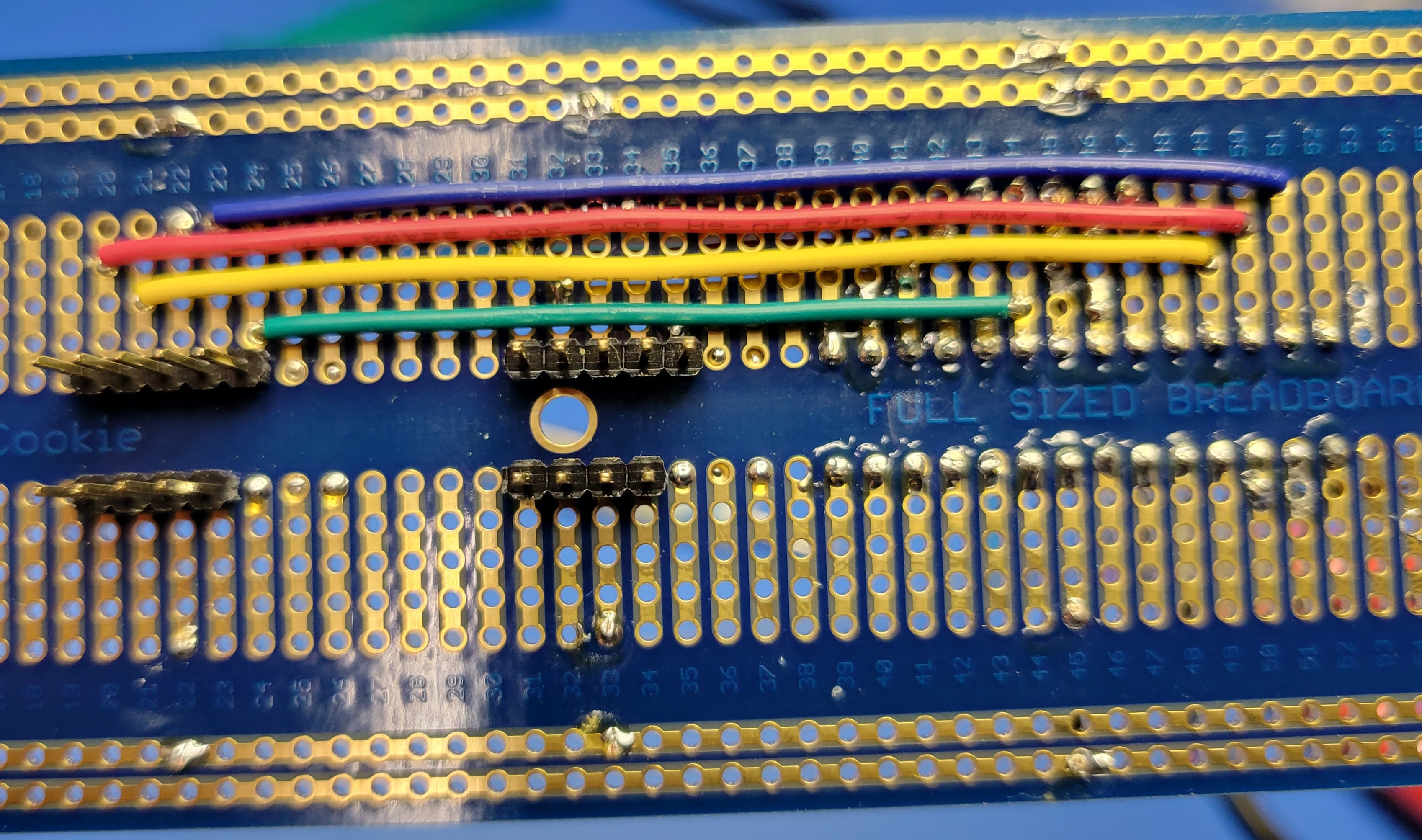
Now the +5v, ground, switch, data, and clock signals will line up so connecting to the MCU is relatively simple. For the dice count encoder:
- SW (switch) to MCU pin 28 (Row 39 Column J)
- DT (data) to MCU pin 27 (Row 40 Column J)
- CLK (clock) to MCU pin 26 (Row 41 Column J)
For the dice type encoder:
- SW (switch) to MCU pin 25 (Row 42 Column J)
- DT (data) to MCU pin 24 (Row 43 Column J)
- CLK (clock) to MCU pin 23 (Row 44 Column J)
![]()
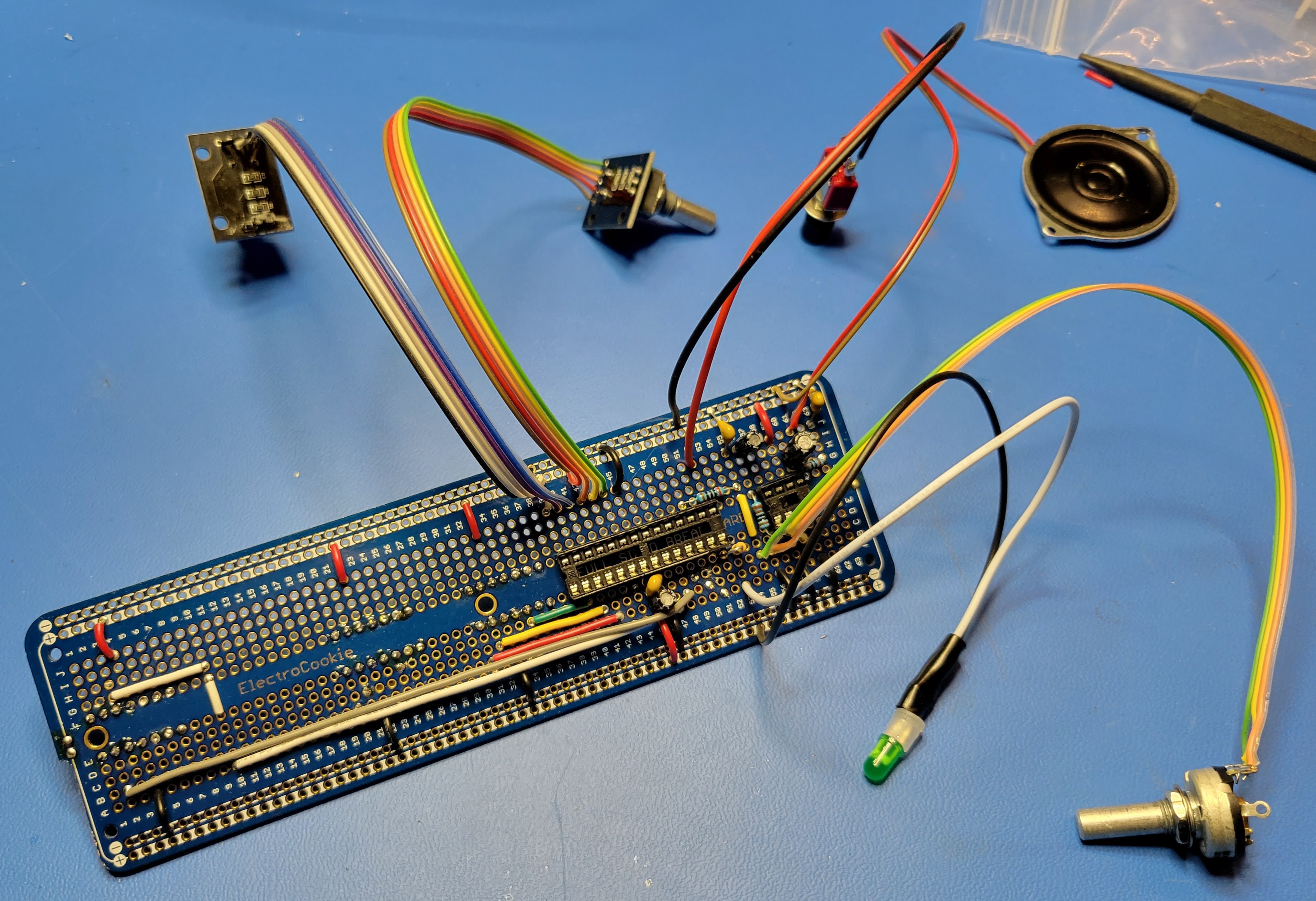
When you are done, your controller board should look like this octopus.
![]()
In the next blog, we'll apply face plate graphics, install the controller board, and mount the indicators and controls.
-
Build the Controller (Part 2)
08/16/2022 at 05:02 • 0 commentsNow it's time to solder the connections to the nixie display drivers, lamp transistors/drivers, and the current limiting resistor for the LED result indicator.
Do these steps in the order presented and it will make the soldering easier.
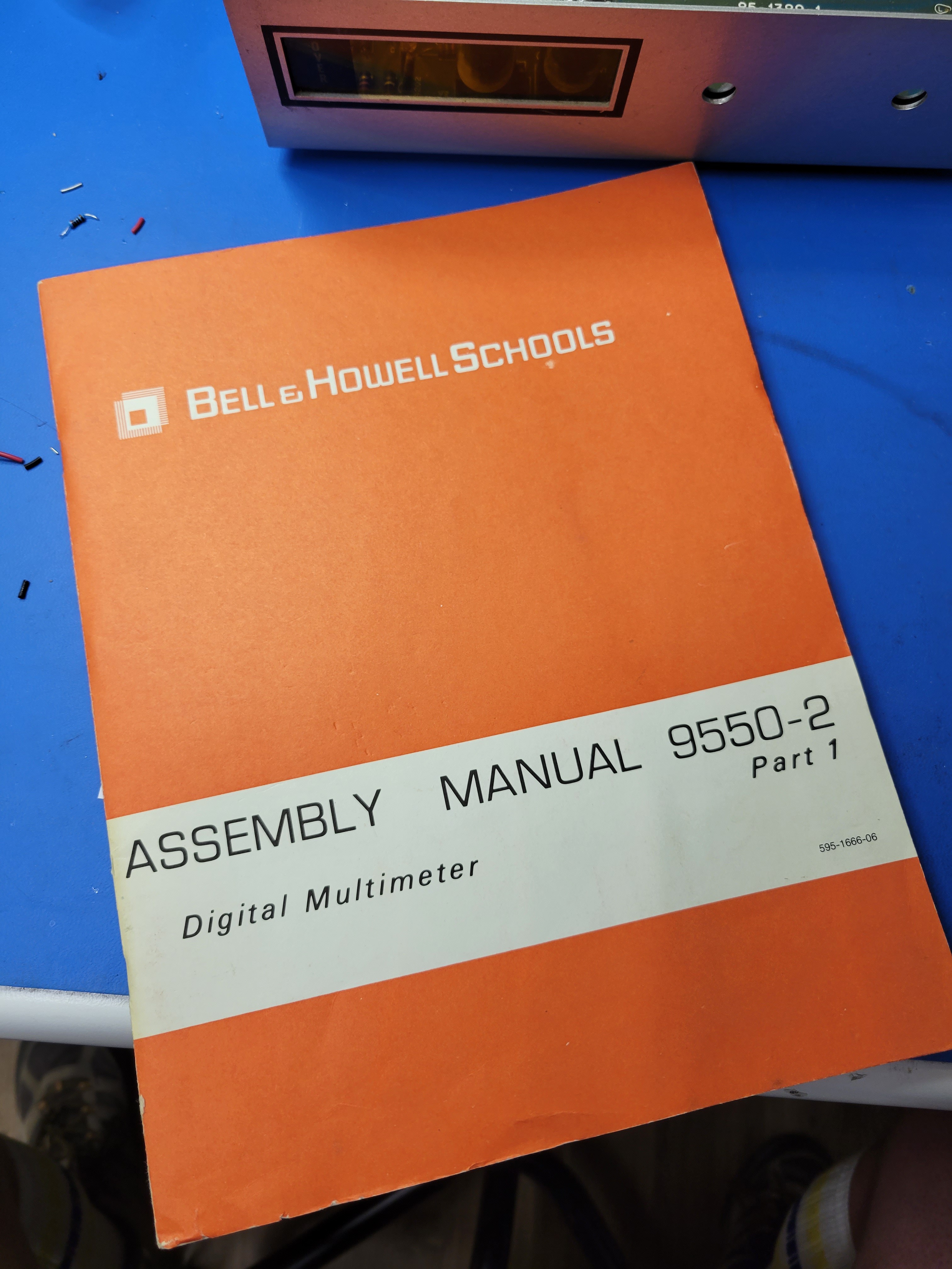
First, determine where to connect the microcontroller digital outputs to the 1's Nixie digit. For this, I happen to have the original assembly manual for these digital multi-meters.
![]()
And it has a full schematic of the circuit board.
![]()
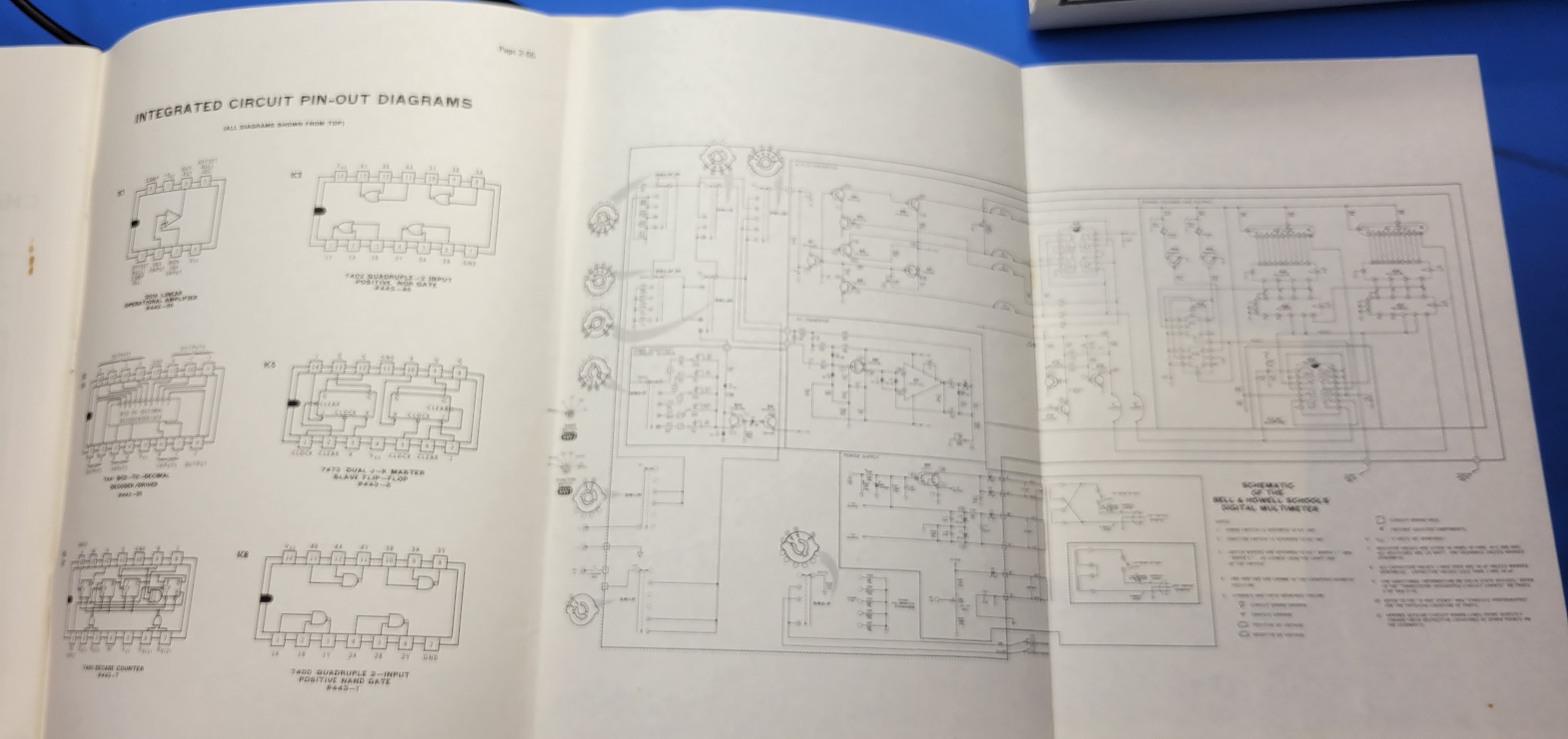
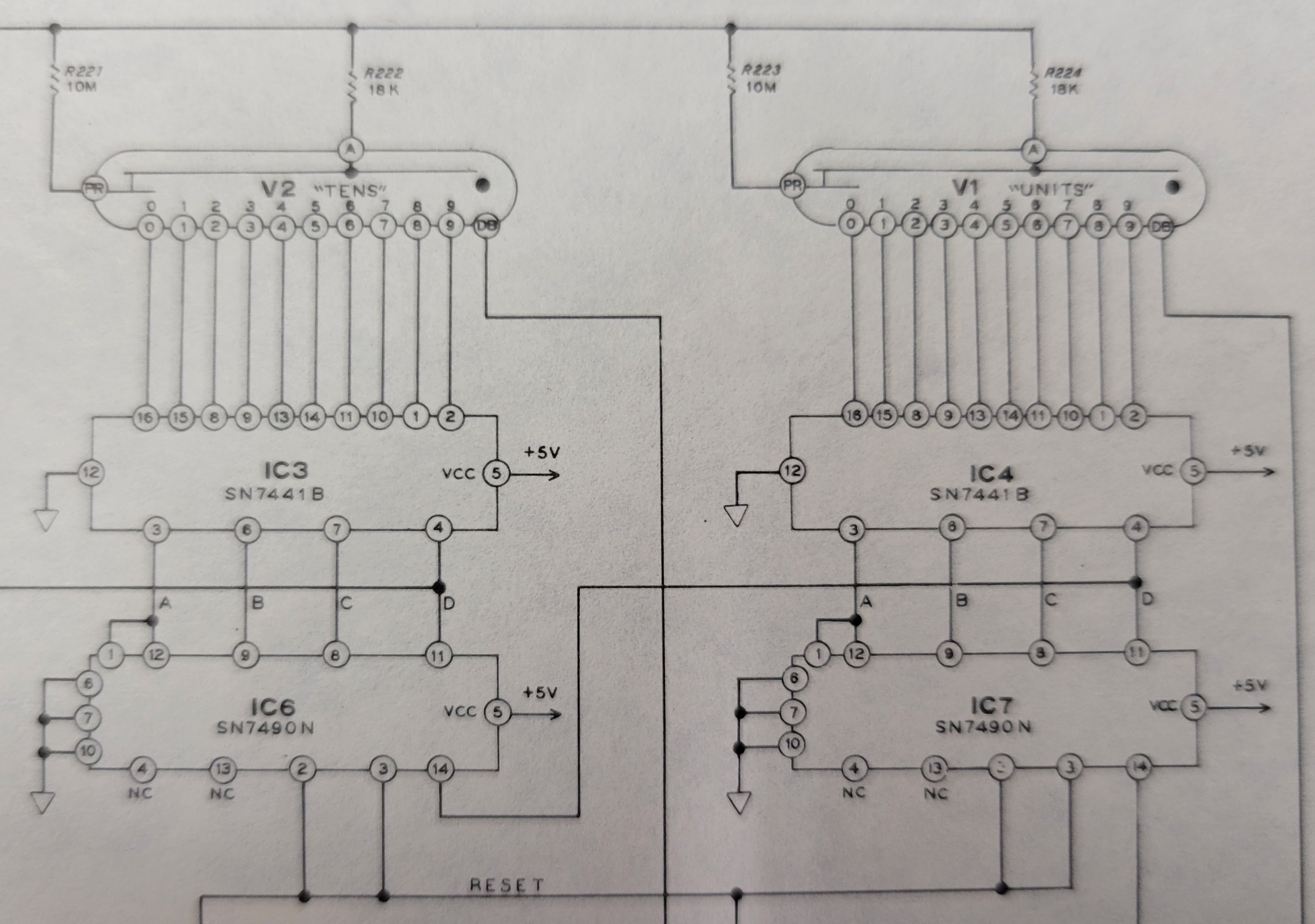
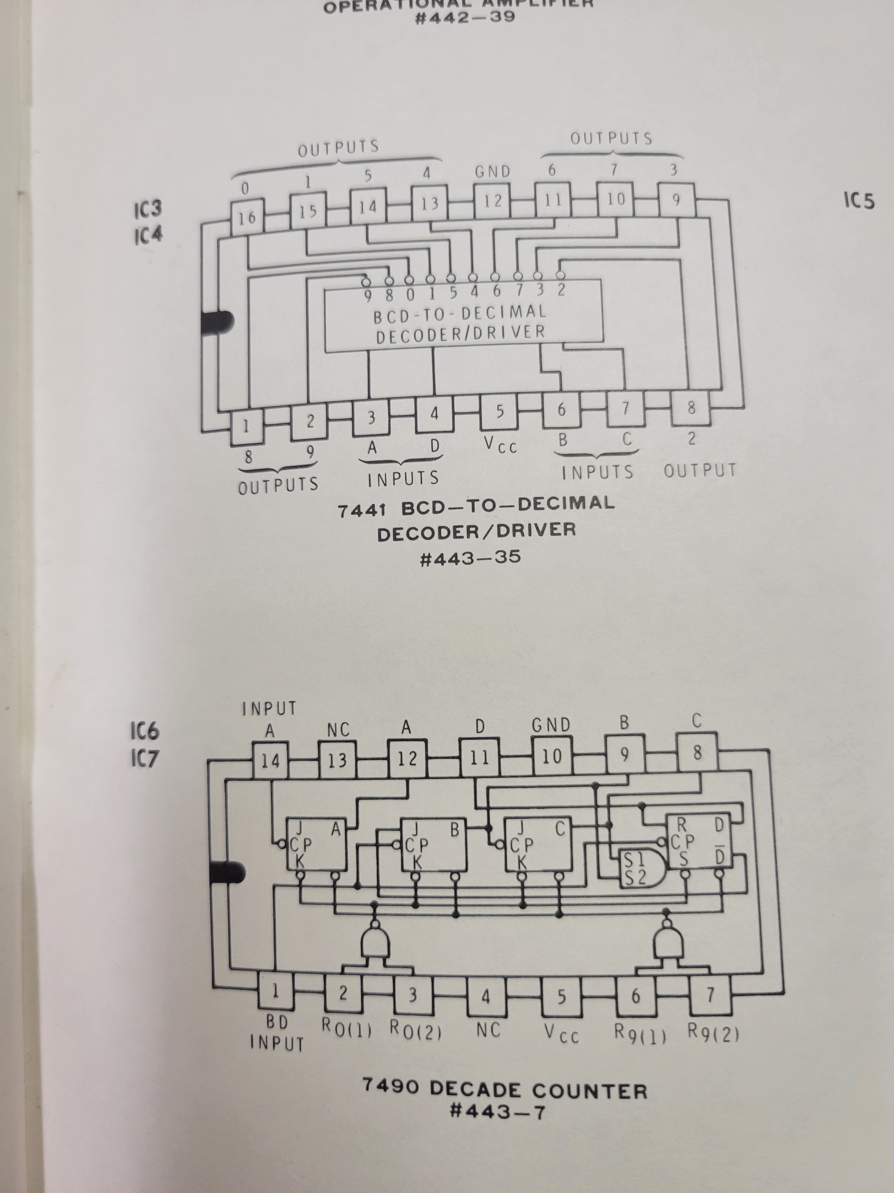
I won't bore you with all the details. But, we are interested in how to drive the Nixie displays. So, here's the relevant part of the schematic. It shows how the original 7490 decade counters (IC6 and IC7) connected to the 7441 BCD to decimal decoder/drivers (IC3 and IC4).
![]()
The controller board plugs into the sockets that used to contain IC6 and IC7. The interface here between the old 7490 decade counters and the 7441 decoder/drivers is TTL logic levels. This is compatible with the digital outputs on the ATmega 328P microcontroller. So, wiring this up will be simple. The outputs from the microcontroller can directly drive the inputs on the 7441 decoder/drivers.
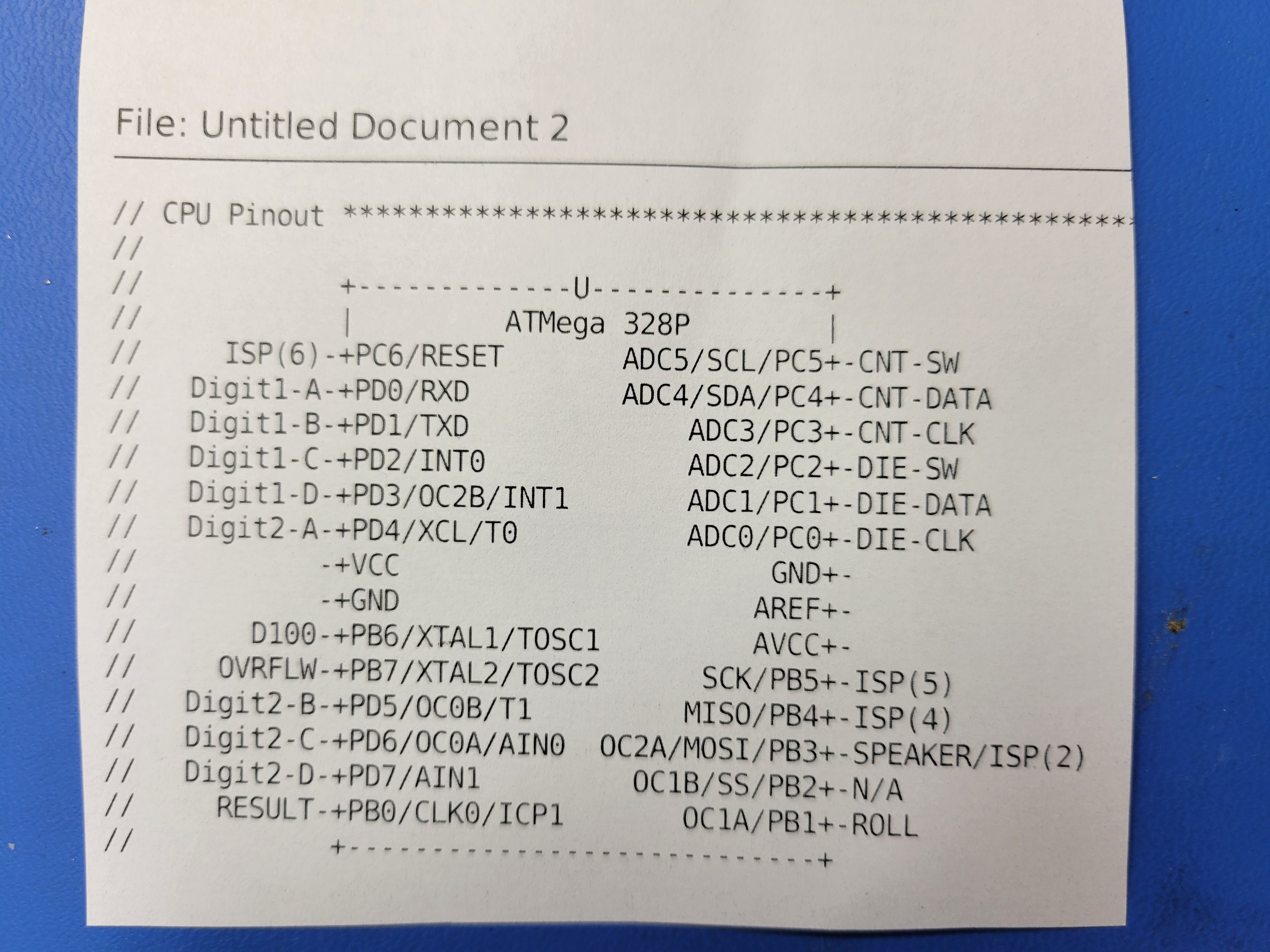
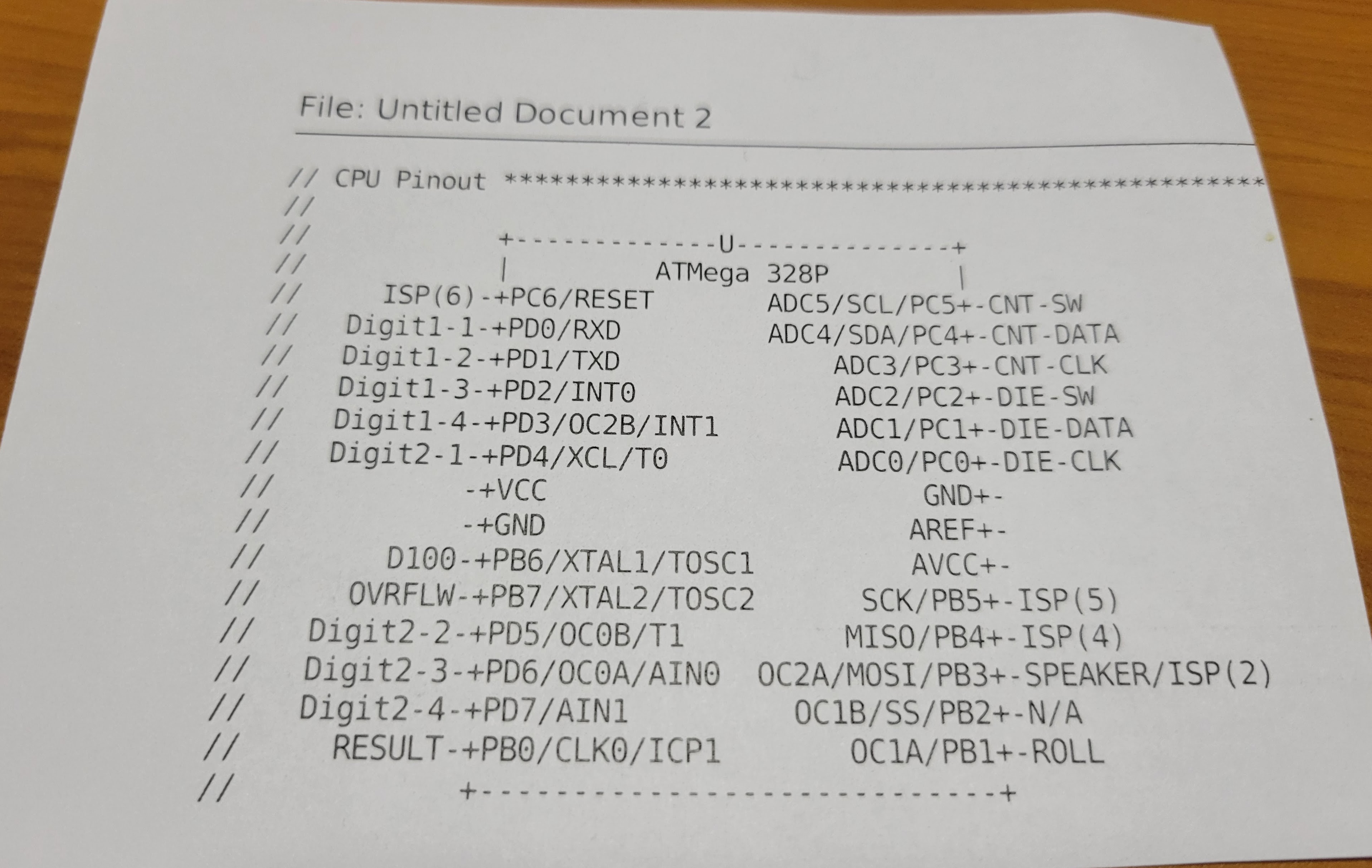
Here's the pinout for the microcontroller. Pins 2-5 are the outputs for the 1's digit.
![]()
On the controller board, it looks like this for the 1's digit Nixie display.
- Pin 2 (row 40 column D) of the microcontroller connects to pin 12 (row 35 column D) of IC7
- Pin 3 (row 41 column C) of the microcontroller connects to pin 9 (row 32 column C) of IC7
- Pin 4 (row 42 column B) of the microcontroller connects to pin 8 (row 31 column B) of IC7
- Pin 5 (row 43 column A) of the microcontroller connects to pin 11 (row 34 column A) of IC7
Run these wires on the top side of the board and solder from the bottom side.
![]()
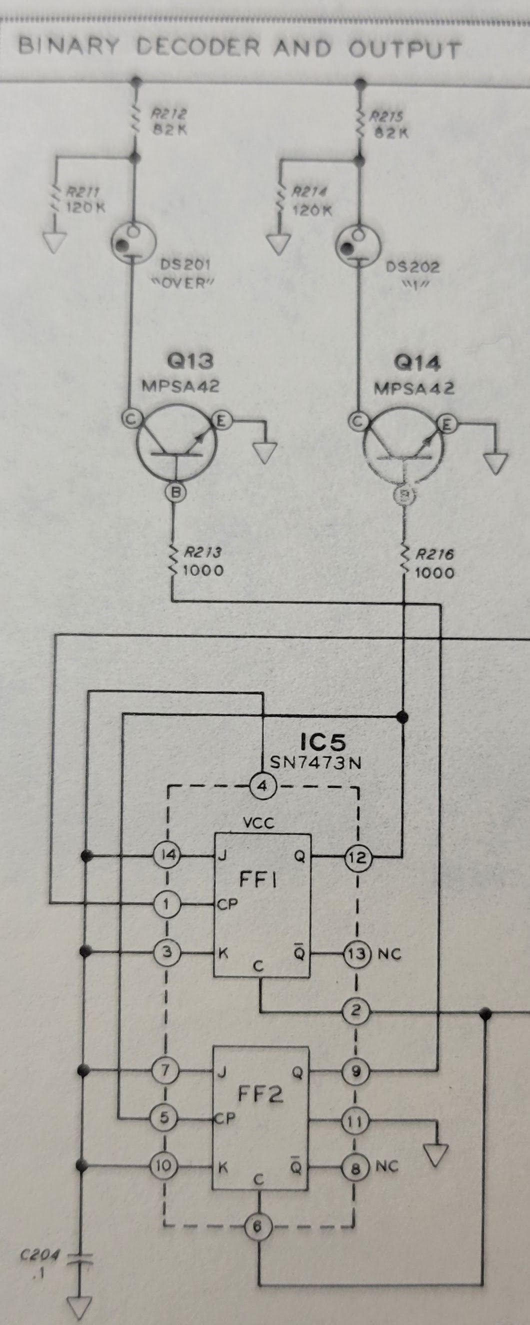
Next, connect the 100 digit (it's just a neon lamp representing the digit 1) and the overflow indicator (another neon lamp).
As you can see from the original schematic, the 1's digit is driven by pins 5 and/or 12 on IC5. The overflow indicator is driven by pin 9 on IC5. Again, these are TTL level compatible. So, they can be driven directly by the microcontroller.
![]()
It looks like this on the controller board.
- Pin 9 (row 47 column A) of the microcontroller connects to pin 5 (row 3 column G) of IC5
- Pin 10 (row 48 column B) of the microcontroller connects to pin 9 (row 2 column B) of IC5
In hindsight, I could have connected 100's digit to pin 12 of IC5 and saved the jumper wire between rows 10 and the wire from row 10 column G to row 3 column G. That would have required a 5 pin header instead of the 4 pin header I had installed. Lesson Learned: Use a pair of 7 pin headers for the IC5, IC6, and IC7 socket connections.
![]()
Now, wire up the connections for the 10's Nixie digit. These wires will be run on the bottom side of the board and soldered from the top side. This will keep everything cleaner.
It looks like this on the controller board.
- Pin 6 (row 44 column D) of the microcontroller connects to pin 12 (row 24 column D) of IC6
- Pin 11 (row 49 column C) of the microcontroller connects to pin 9 (row 21 column C) of IC6
- Pin 12 (row 50 column B) of the microcontroller connects to pin 8 (row 20 column B) of IC6
- Pin 13 (row 51 column A) of the microcontroller connects to pin 11 (row 23 column A) of IC6
![]()
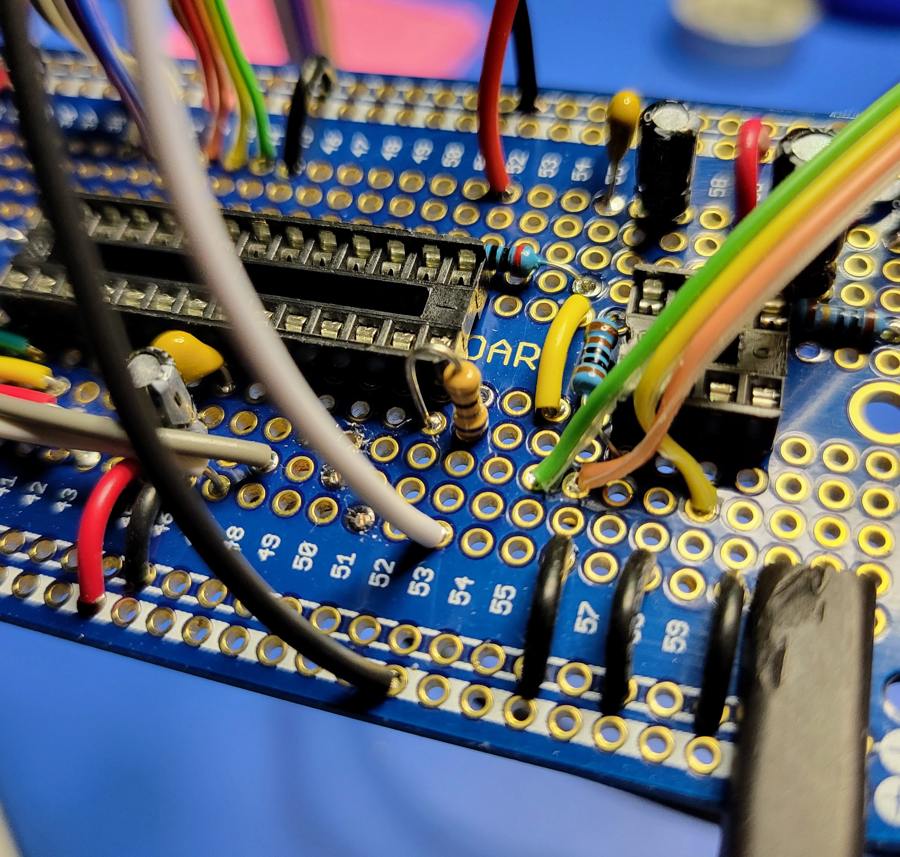
Lastly, solder up the current limiting resistor for the result LED indicator. I am using a 5mm green LED for this. So, I used a 68 Ohm resistor. Pin 14 on the microcontroller drives this indicator. So, solder the resistor from pin 14 (row 52 column D) to row 53 column D. Row 53 columns A, B, C will connect to the positive lead on the LED when we wire up the external switches, speaker, and LED indicator in the next blog.
![]()
With that, all of the visual indicators are wired up.
-
Build the Controller (Part 1)
08/11/2022 at 05:17 • 0 commentsNow that the case and the PCB are prepped and you have soldered the headers that will connect the controller board to the original PCB, you can start building the controller board.
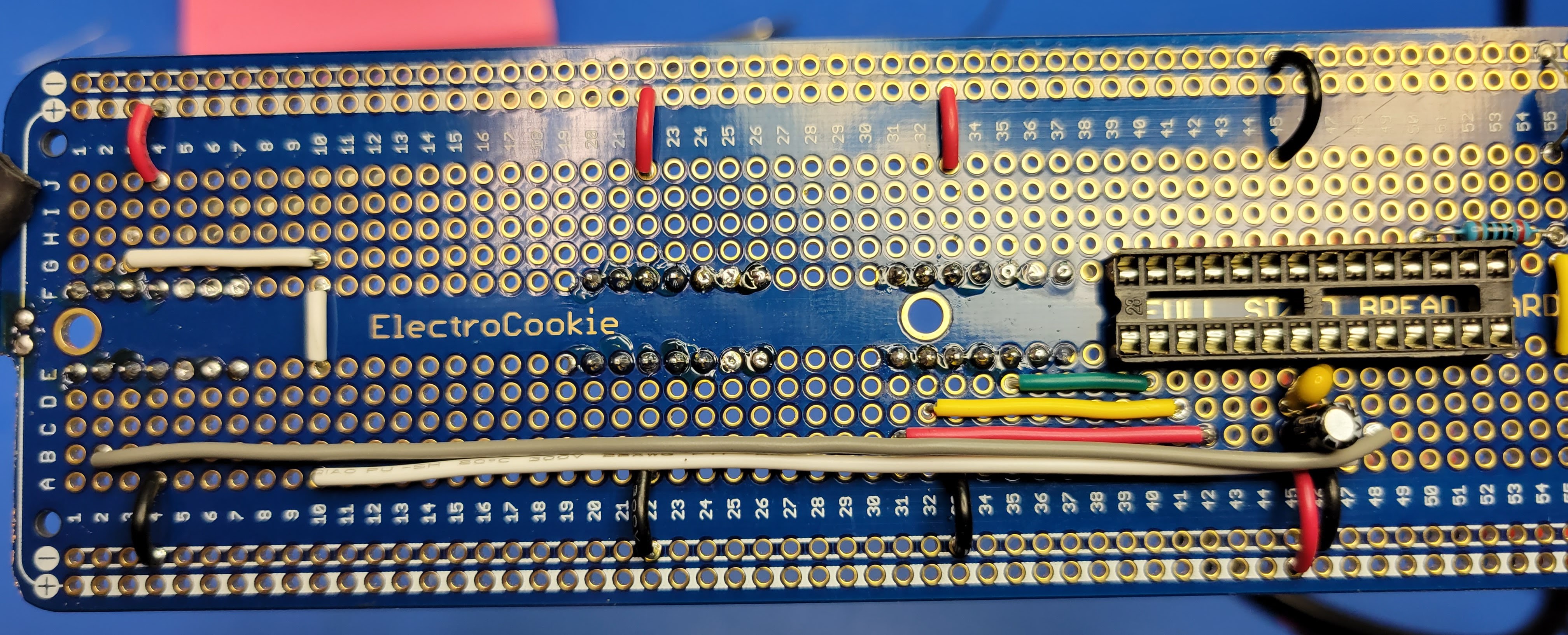
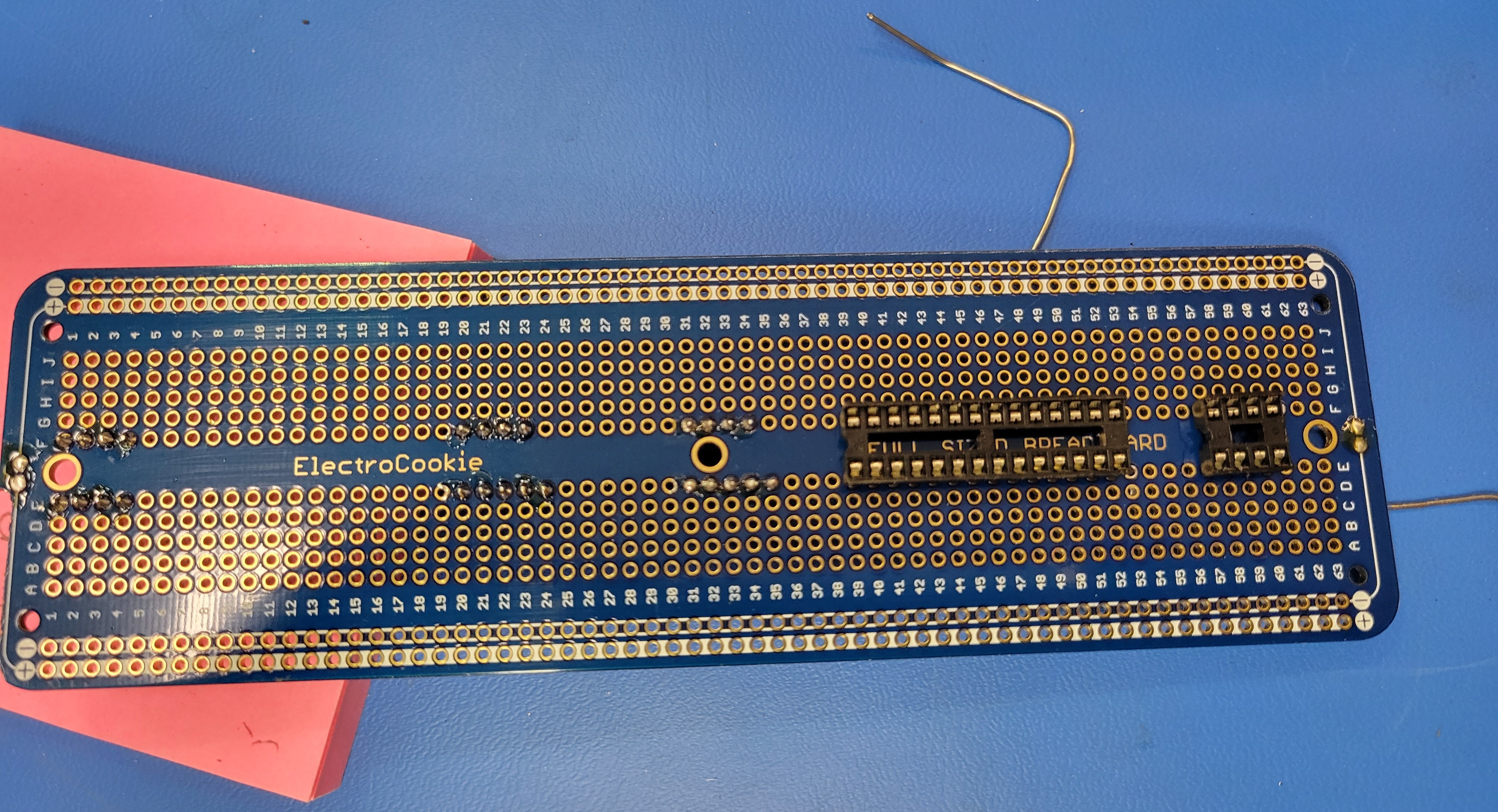
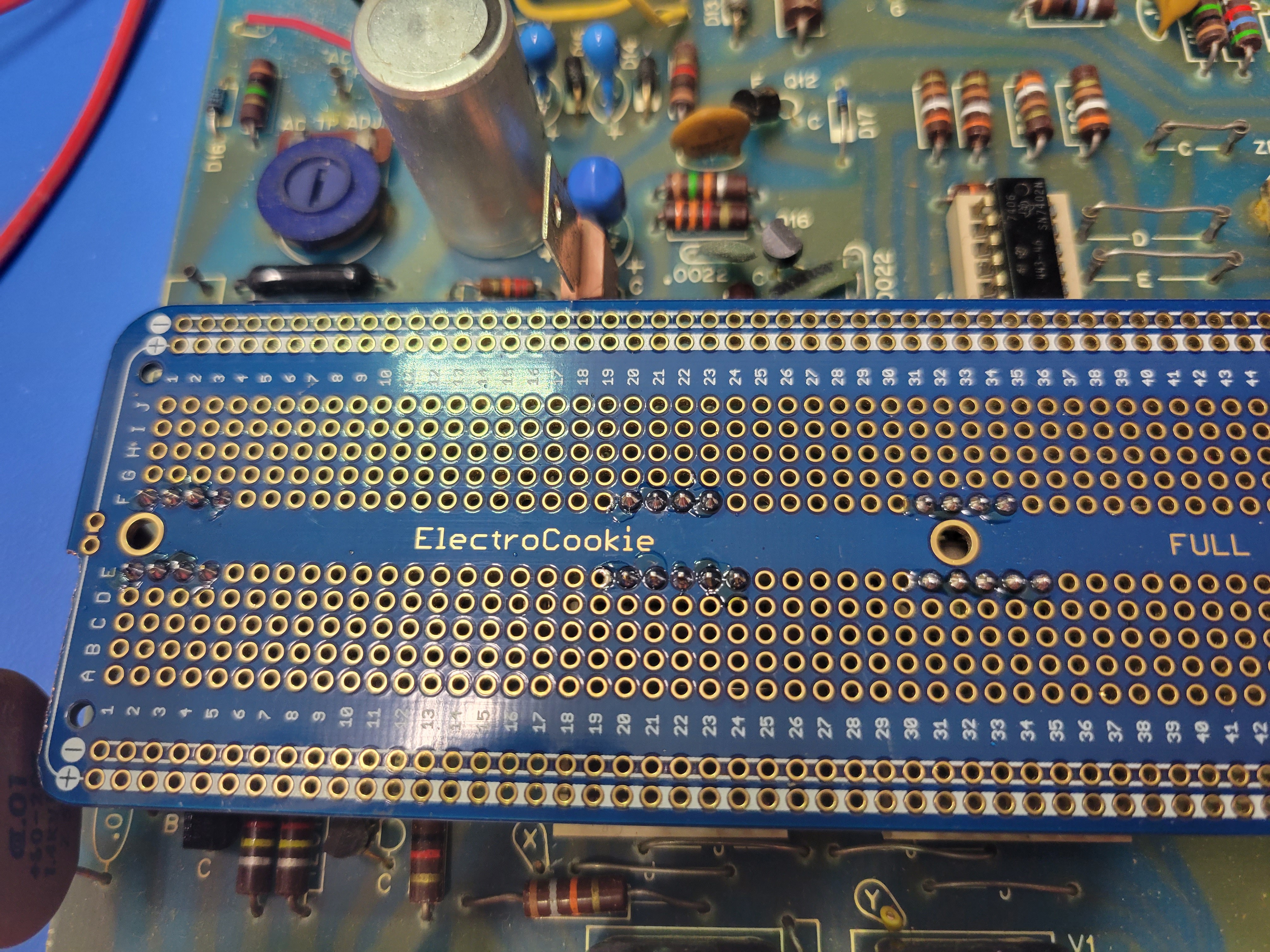
Start by putting a solder blob on both sides of the proto board connecting the left and right side power bus.
![]()
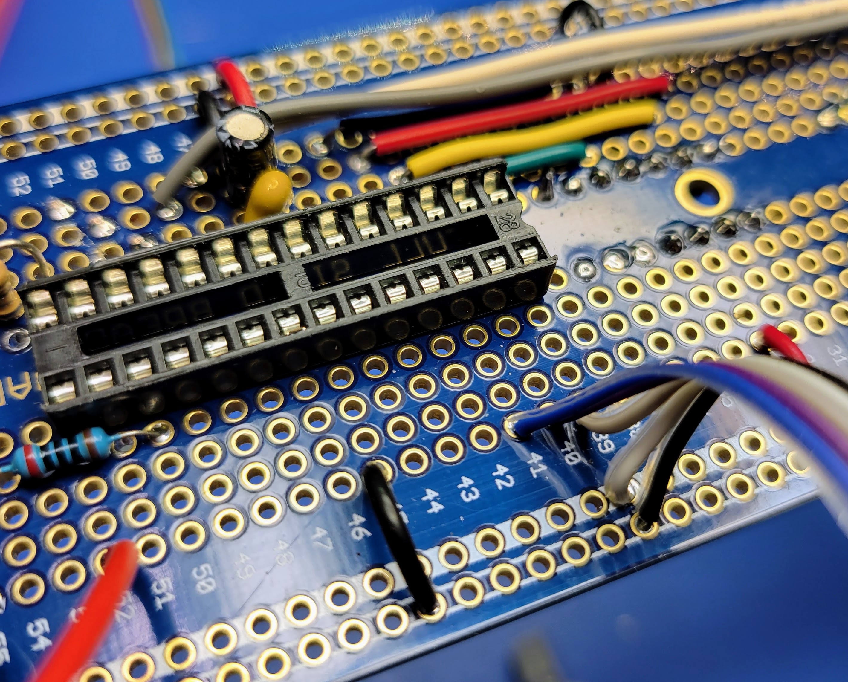
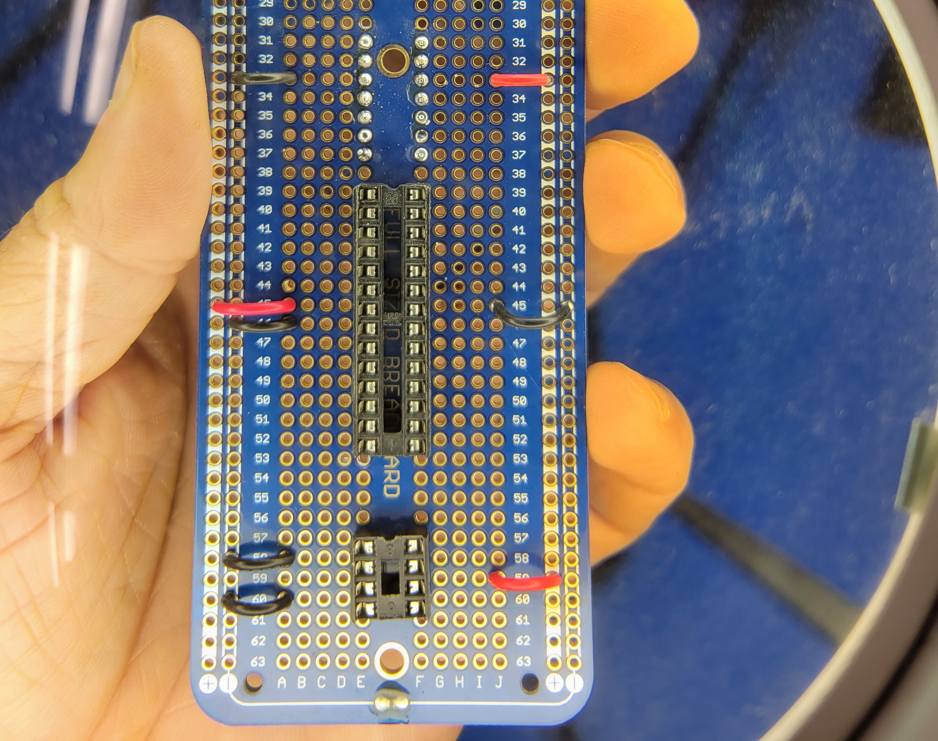
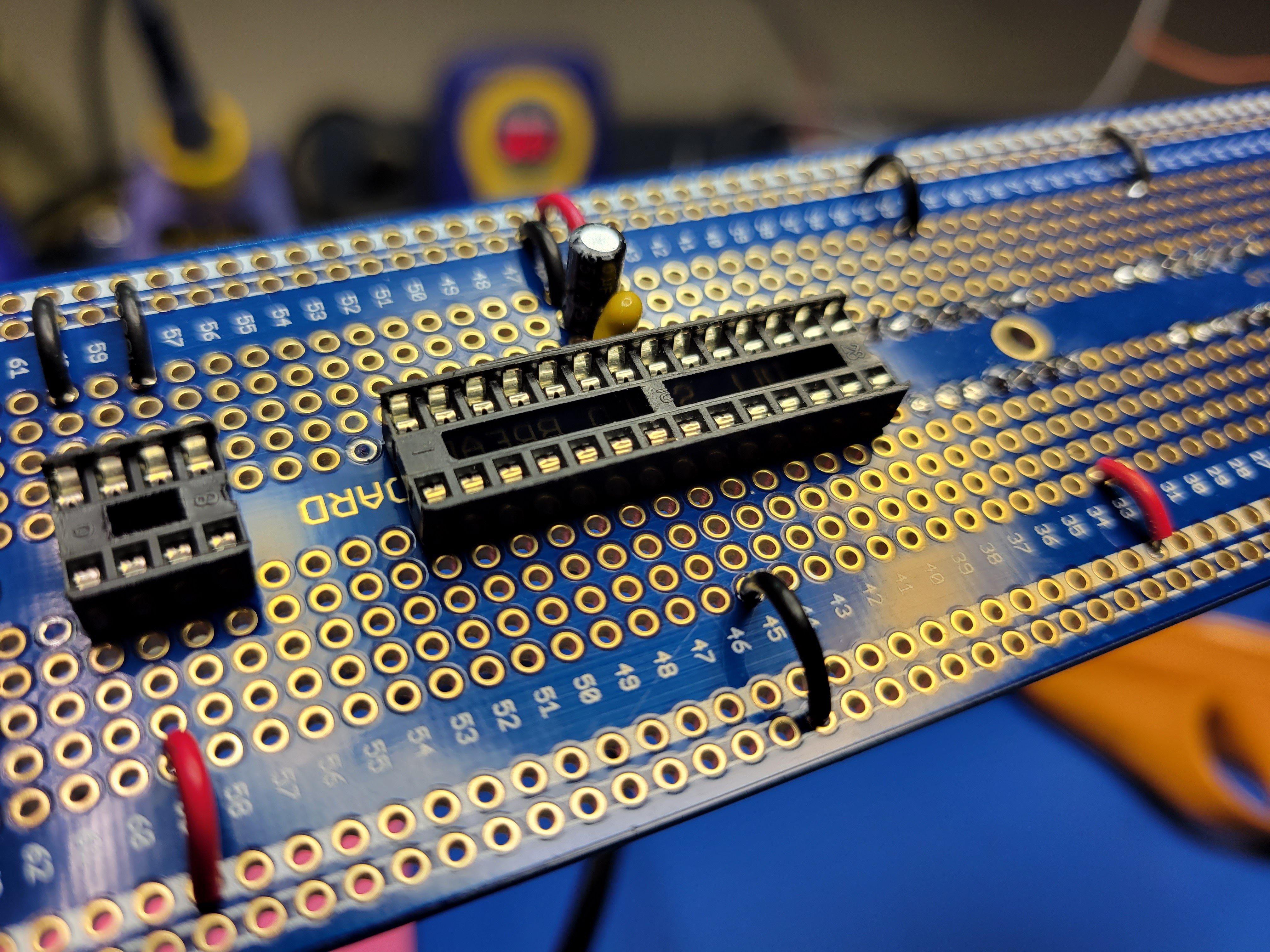
Then locate the 28 pin dip and 8 pin dip sockets on the protoboard as so. If you align them on the same rows I have it will make referencing this photos easier. On my board, pin 1 for the 28 pin dip socket is on row 39 and pin 1 for the 8 pin dip socket is on row 57.
![]()
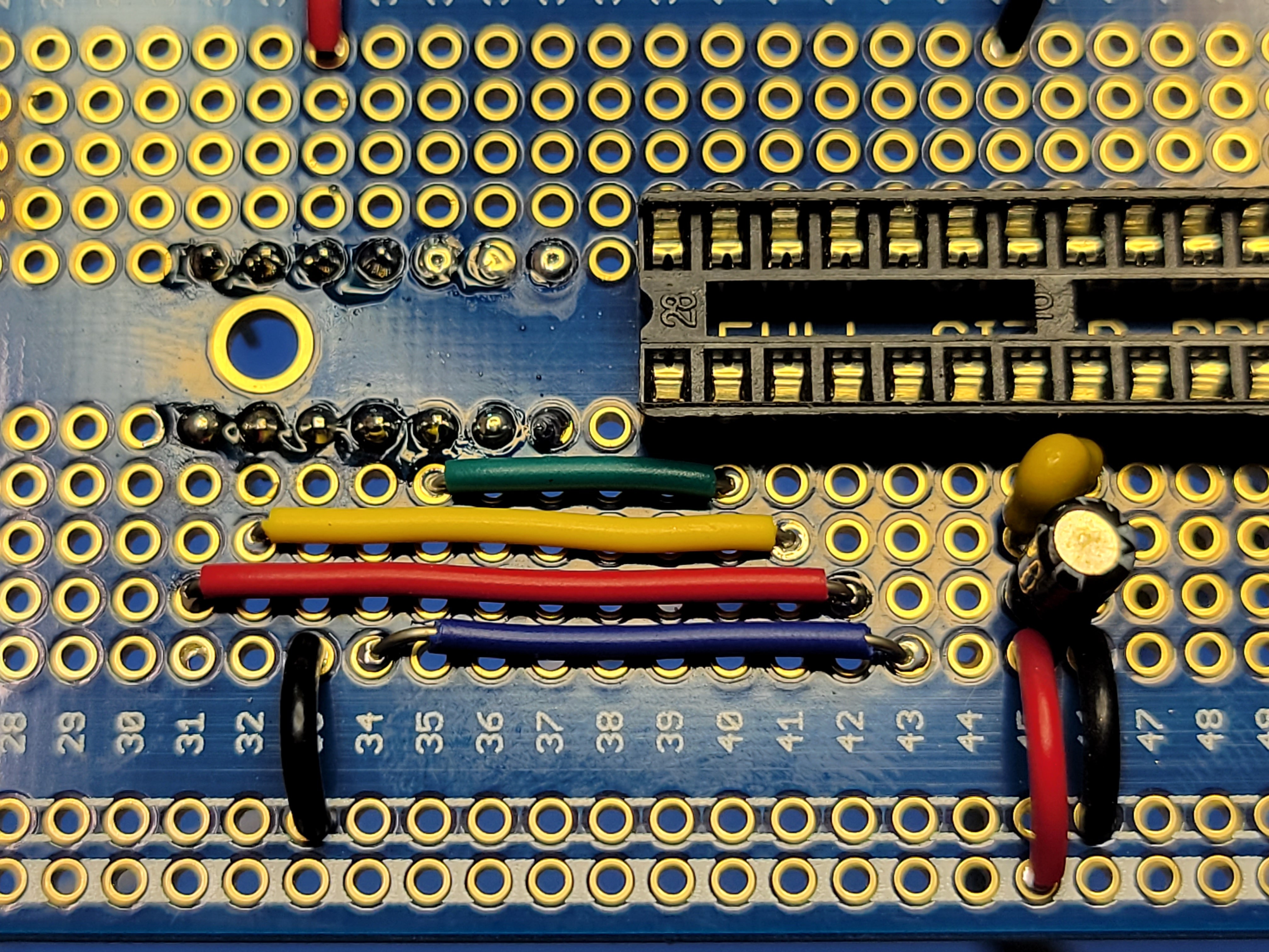
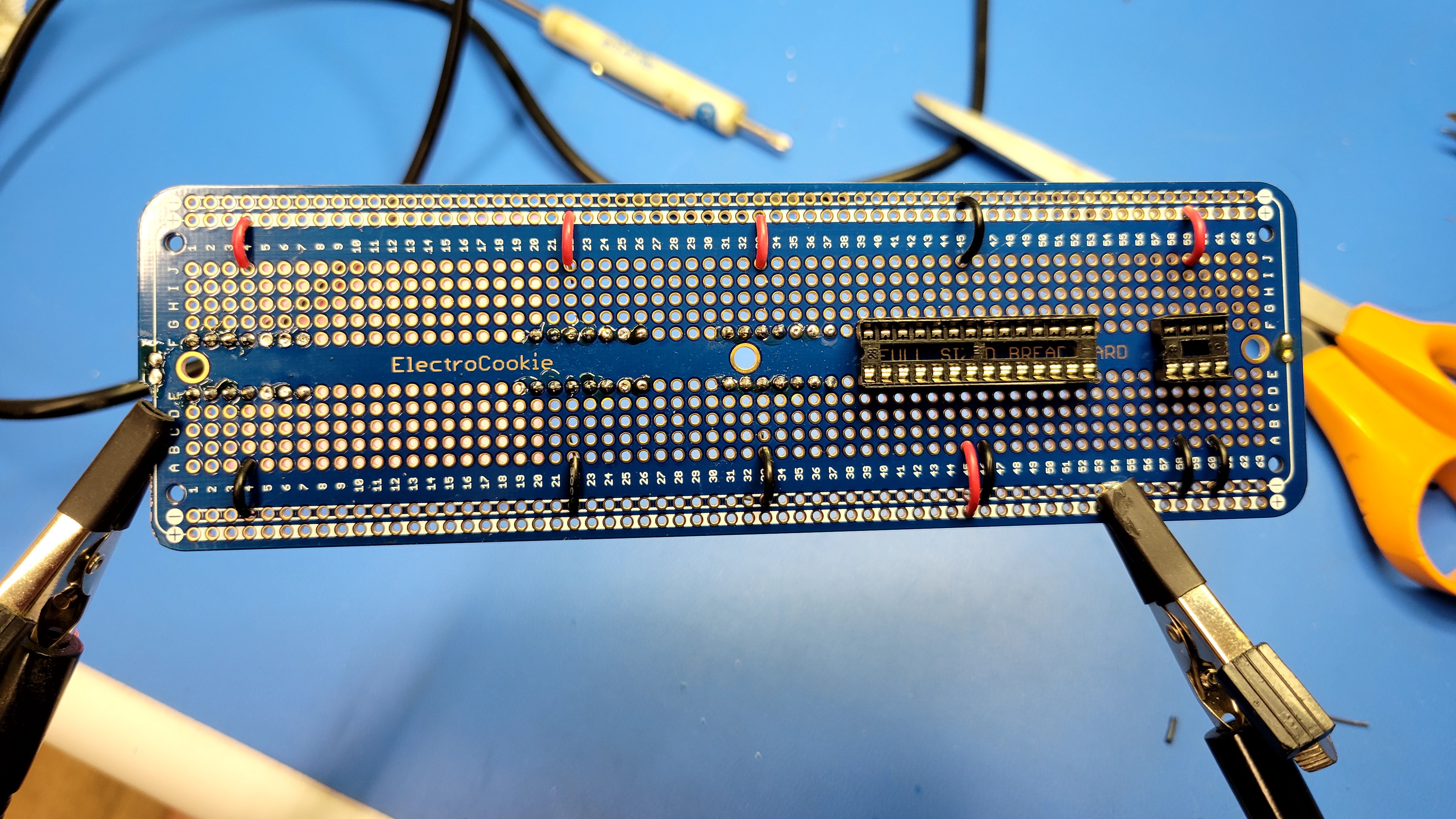
Next wire up the power and ground to the power bus. Wiring power and ground to the headers will provide 5v and ground to the controller board. Wiring power and ground to the 28 pin and 8 pin sockets will provide 5v and ground to the microcontroller and op amp. Note: I have soldered some of the rows adjacent to the headers so that you can see all the pins for IC5, IC6, and IC7. This will help reference the pin numbers for these. Pin 1 for these three is the upper left. Therefore pin 1 for IC5 is the upper row 7, pin 1 for IC6 is the upper row 26, and pin 1 for IC7 is the upper row 37. Pin 1 for the 28 pin microcontroller is the lower row 39 and pin 1 for the 8 pin audio op amp is the lower row 57.
![]()
For the header connections, wire IC5 pin 4 (row 4), IC6 pin 5 (row 22), and IC7 pin 5 (row 33) to the 5v bus. Then wire IC5 pin 11 (row 4), IC6 pin 10 (row 22), and IC7 pin 10 (row 33) to the ground bus.
![]()
For the microcontroller and audio op amp sockets, wire microcontroller pin 7 (row 45) and audio op amp pin 6 (row 59) to 5v bus. Then wire microcontroller pin 8 (row 46), microconroller pin 22 (row 45), audio op amp pin 2 (row 58), and audio op amp pin 4 (row 60) to the ground bus.
![]()
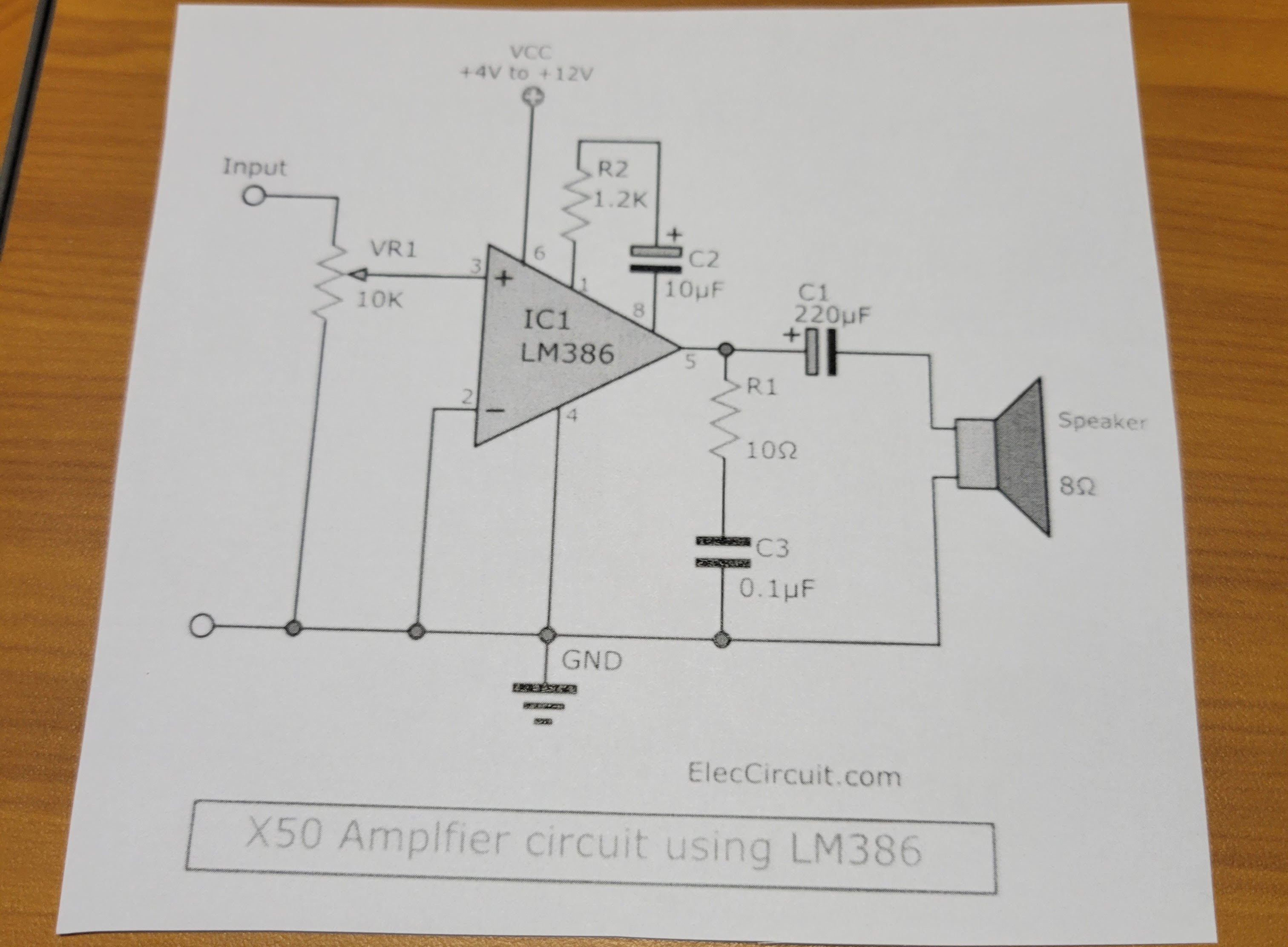
Tip: I print out the pin out for the microcontroller cut it out and post it on my work bench with a magnet so I can reference it easily. You can find this pin out in the comments in the main.c file in the source code I provide (B-H_DiceTower_v3.zip). I do the same for any other circuits I might be wiring up. In this case, I printed out the simple amplifier circuit for the LM386 op amp I am using.
![]()
![]()
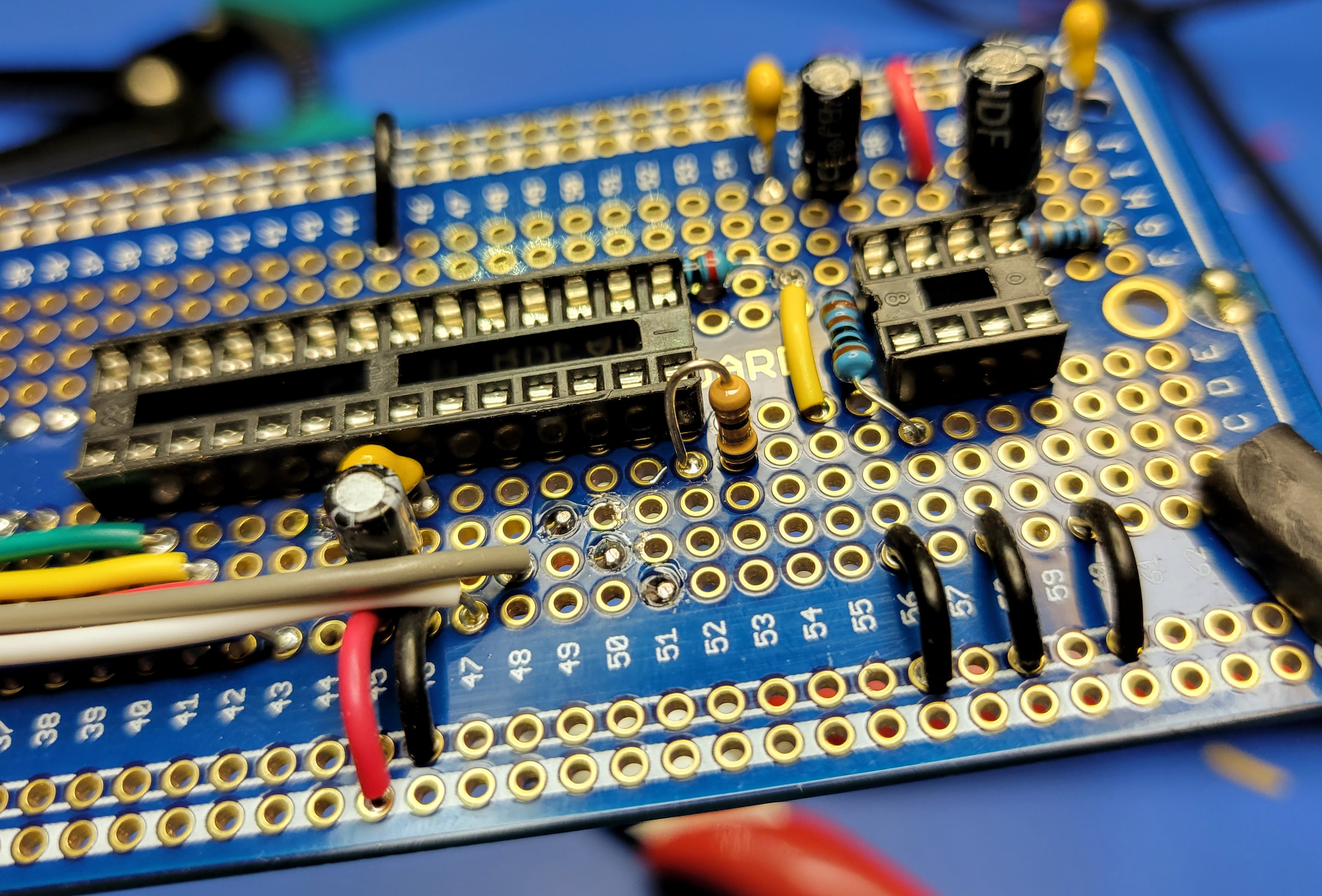
Next, wire up the decoupling caps on Vcc and ground going to the microcontroller. These will filter out noise coming from the power supply. These are the 10 uF electrolytic capacitor and 0.1 uF ceramic capacitor documented in the BOM log. They will be soldered between pin 7 (row 45) and pin 8 (row 46). When soldering in the electrolytic capacitor pay attention to the polarity. You will need to connect the negative lead to ground (pin 8 on the microcontroller). Note: I later added a 10uF decoupling capacitor to the power pin (pin 6, row 59) of the audio amp IC. This reduced the noise in the audio circuit.
![]()
Next start wiring up the audio circuit. First wire up the feedback for the amplifier gain. This requires the 10 uF electrolytic capacitor and 1K Ohm resistor from the BOM. Again pay attention to the polarity of the capacitor. The negative lead should be soldered to pin 8 (row 57) and the other lead with be soldered to row 56. Then the 1K Ohm capacitor will be soldered from the same row 56 to pin 1 (row 57) of the op amp. Note: The 1K Ohm capacitor provides about 40x gain. I found this to be a little quiet with the cheap LM386 ICs I purchased. So, I soldered a jumper wire from row 56 to pin 1 (row 57). This bypassed the 1K resistor and provide 200x gain. Sound was better. If you use a reputable LM386-1 IC you may or may not need to do this. It also will depend on the speaker you select. A 4 ohm speaker will be louder than an 8 ohm speaker.
![]()
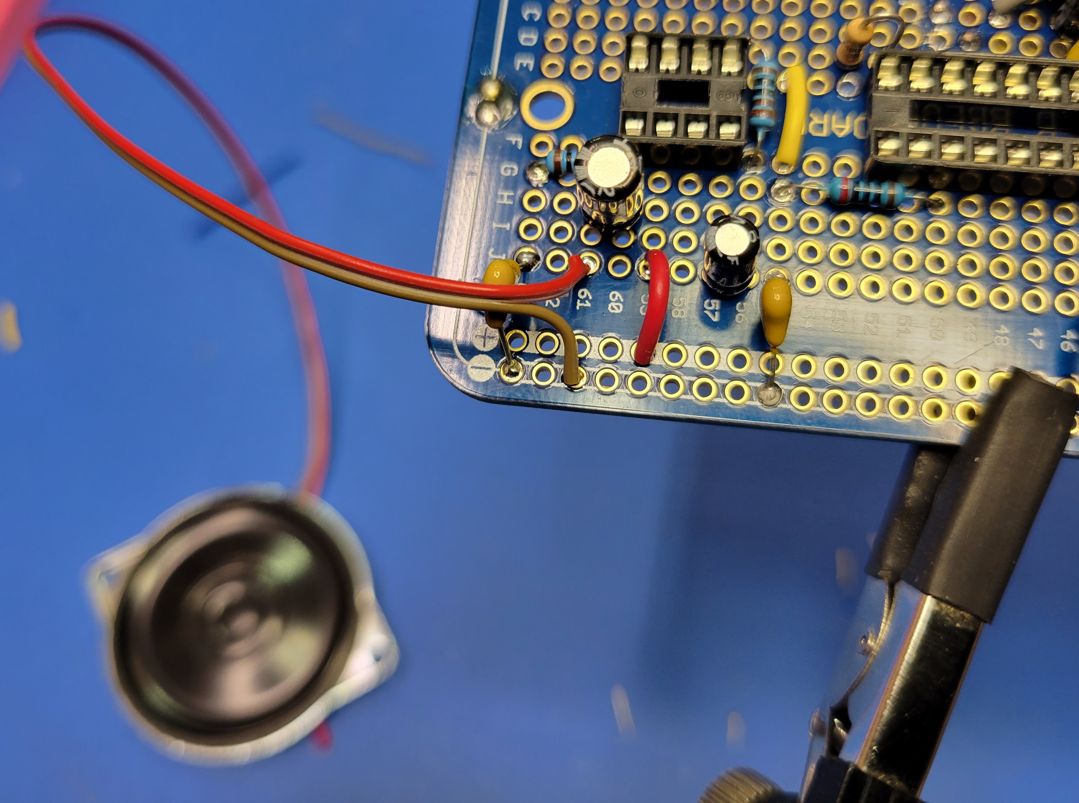
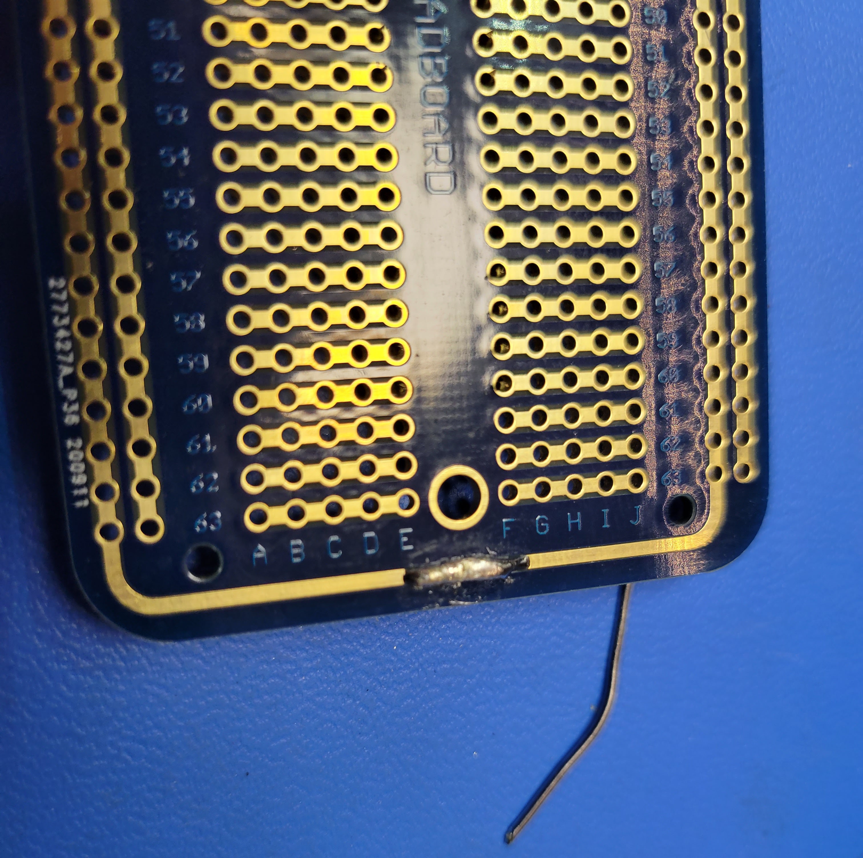
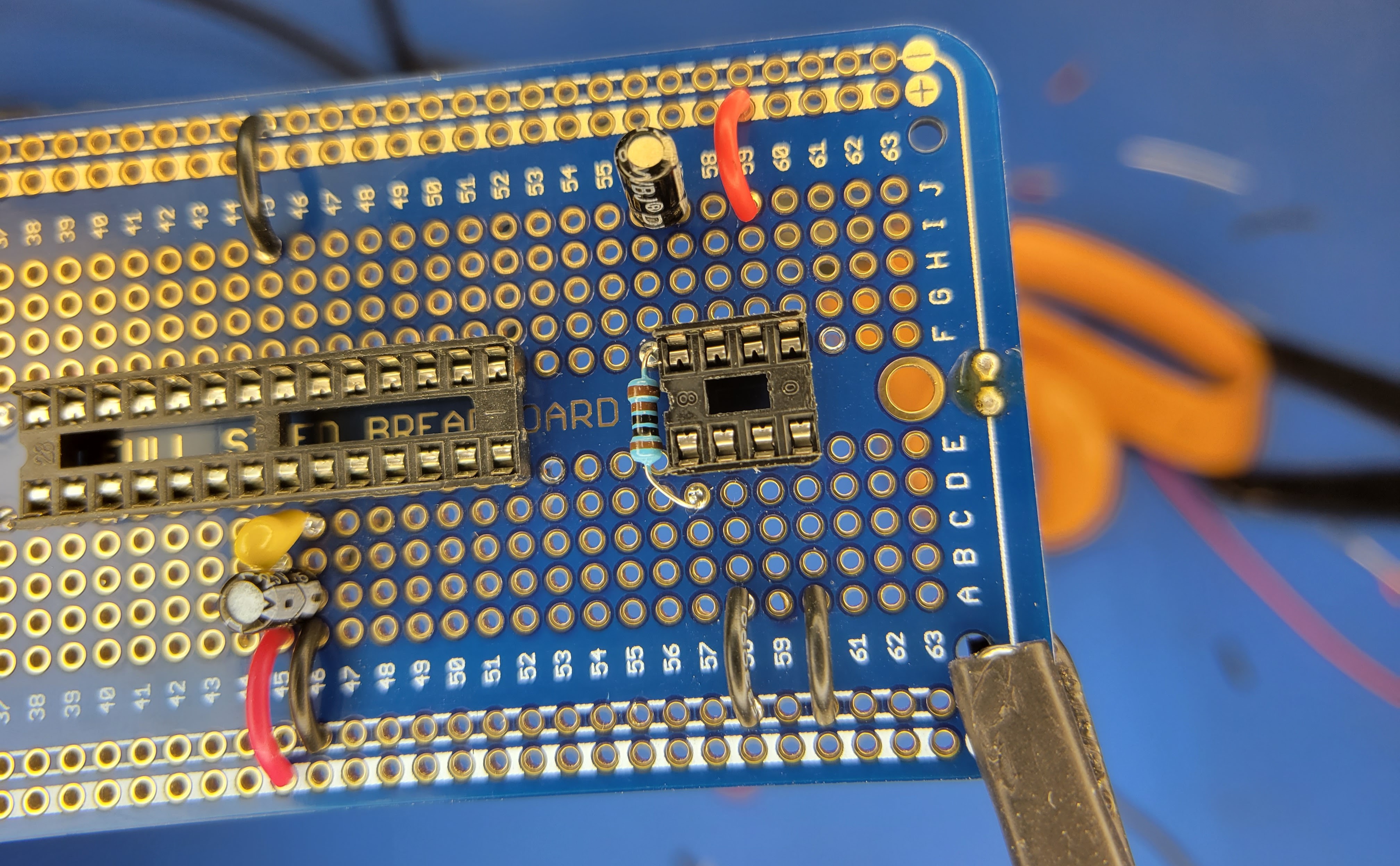
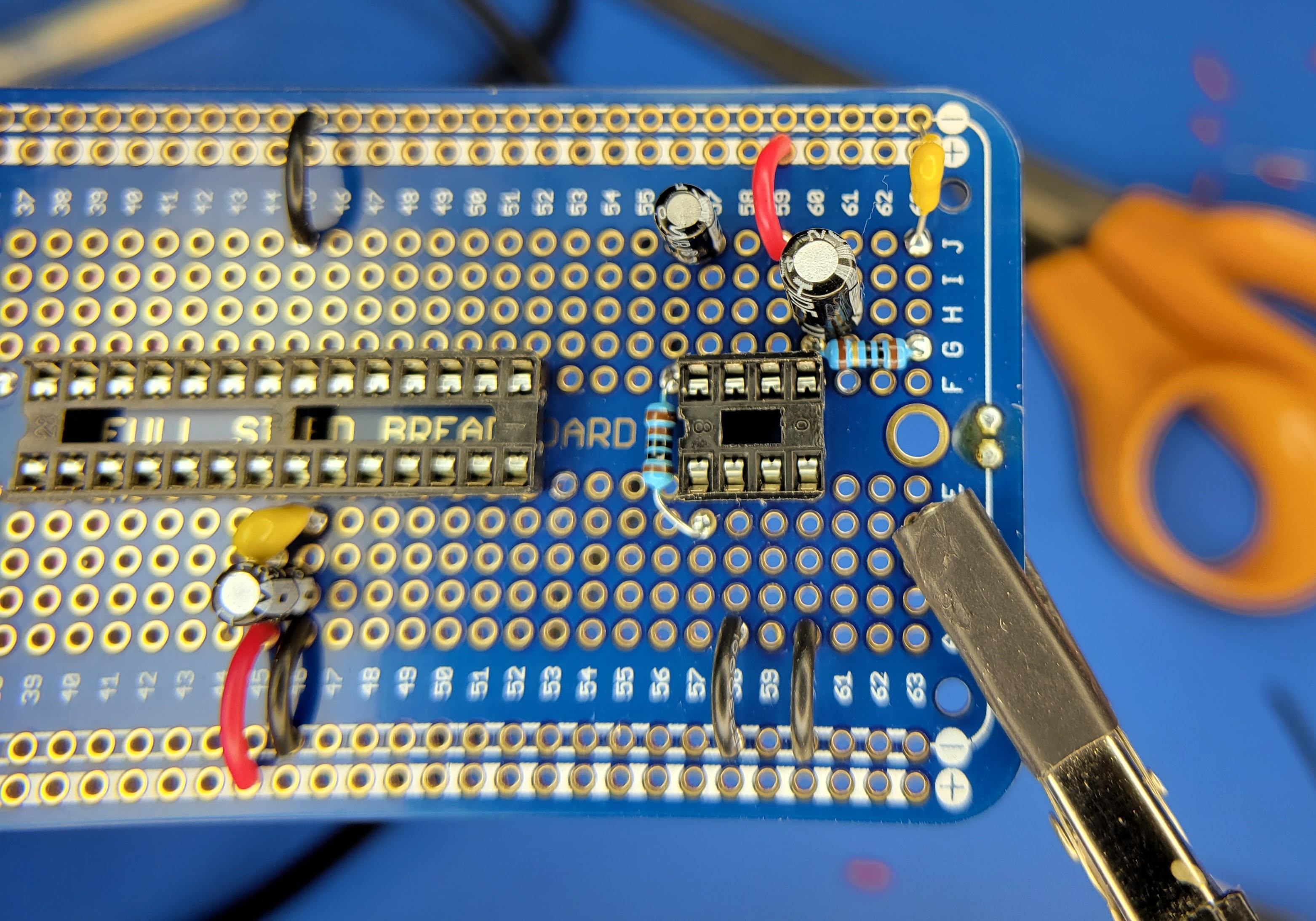
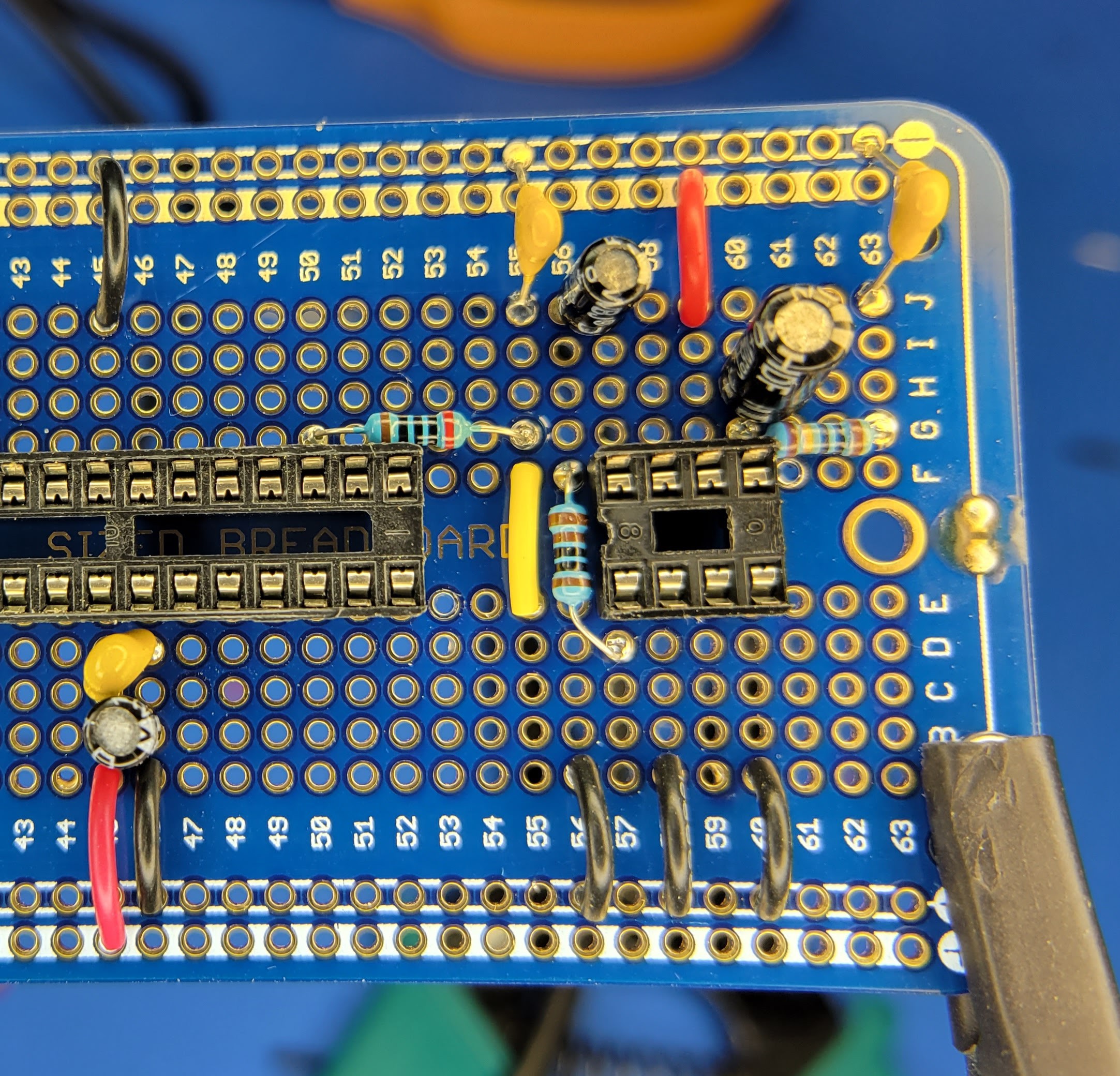
Next wire up the output filter. This requires the 10 Ohm resistor, 0.1 uF ceramic capacitor, and 220 uF electrolytic capacitor. Solder the 220 uF electrolytic capacitor positive lead to pin 5 (row 60). The negative lead will solder to row 61. This row will be the positive (+) output to the speaker when it is wired up later. Solder the 10 Ohm resistor from pin 5 (row 60) row 63. And finally, solder the 0.1 uF ceramic capacitor from row 63 to the ground bus.
![]()
Next wire up the audio output from the microcontroller pin 17 (row 50) to the 10K Ohm potentiometer and the audio amp. This will include a RC low band pass filter to further reduce unwanted noise. Start by soldering the 200 Ohm resistor from pin 17 (row 50) to row 55. Then solder the 0.1 uF ceramic capacitor to row 55 and the ground bus. Next solder a jumper wire (yellow) between row 55 and row 55 on the other side of the protoboard. This will be the output to the "fixed end" of the potentiometer. Finally, solder another jumper wire from the ground bus to row 56 A-E side of the board. This will be the ground for the other "fixed side" of the potentiometer. The wiper for the potentiometer will be wired pin 3 (row 59) of the op amp. The potentiometer will be wired up in a later log post.
![]()
Now you have the power and audio portions of the controller board wired up. It's a good time to check your power from the PCB. Connect the controller board back to the PCB, plug in the meter, and turn it on. Do not insert the microcontroller or the op amp into the sockets at this time. Then check the DC voltage between pin 7 (row 45) and pin 8 (row 46) on the microcontroller socket. You should get something stable and close to 5v.
Next we will wire up the interface to the nixie tube drivers and the transistors that drive the 100 hundred digit and the overflow indicator.
-
Prep the Case and Board
08/02/2022 at 07:15 • 0 commentsOnce you have assembled the parts, it's time to get busy building.
Start by removing the four screws that hold the top portion of the case to the base. There are two screws on each side of the meter.
![]()
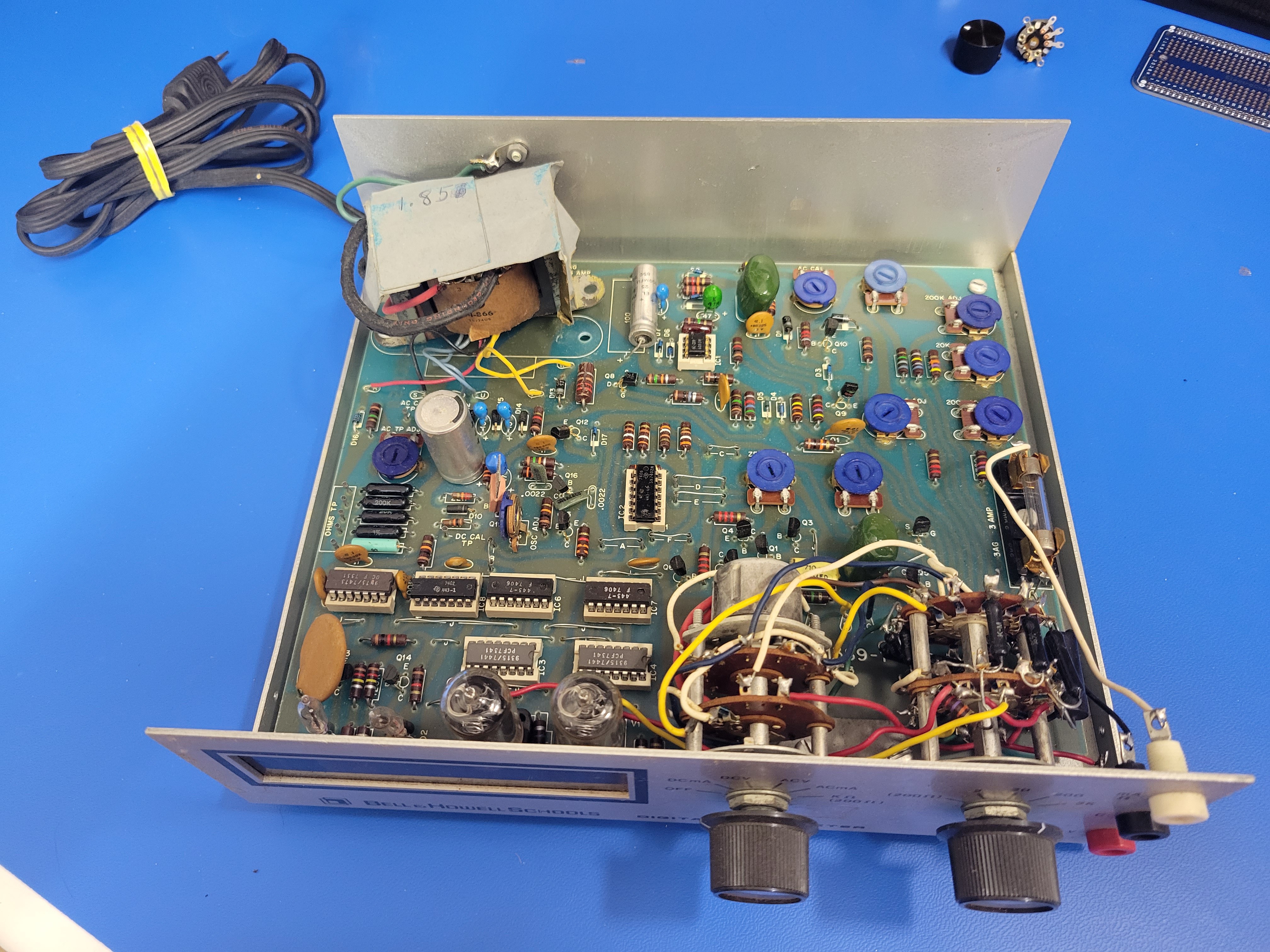
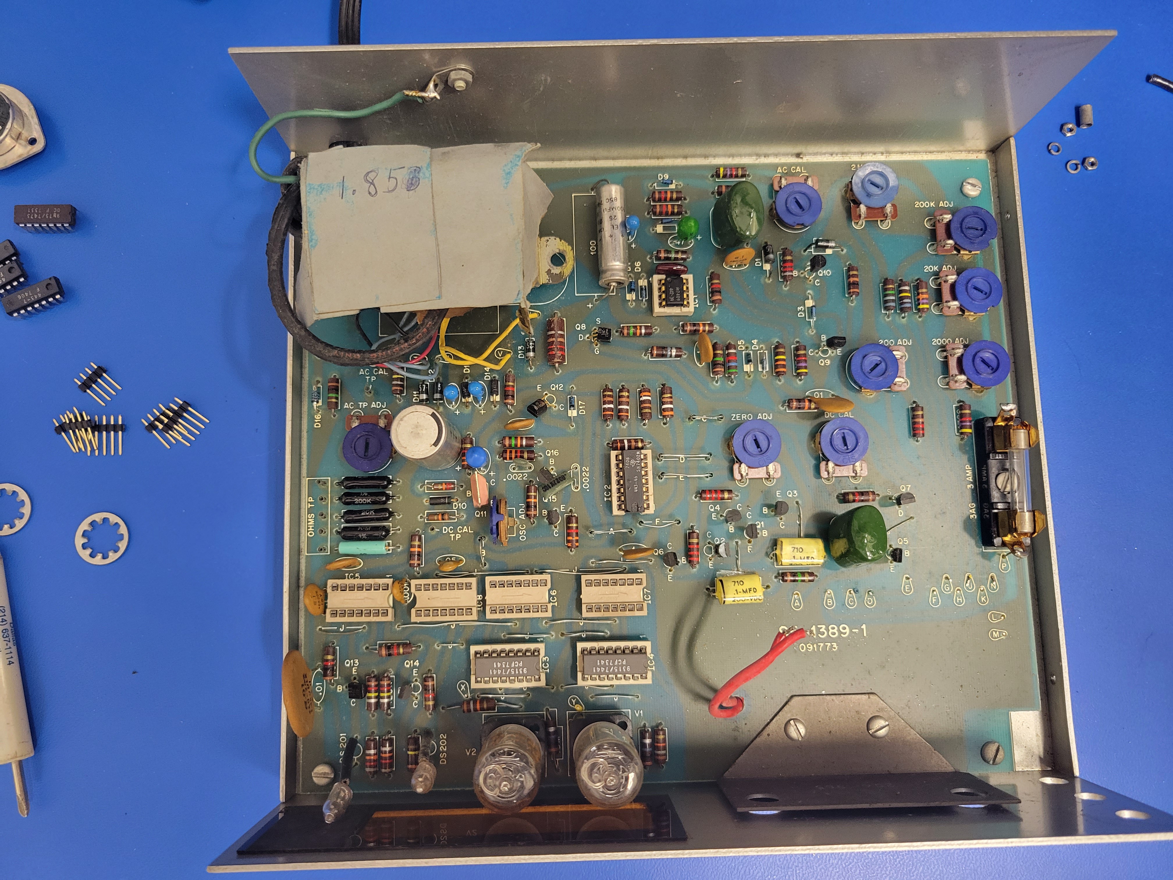
Once it's open, hopefully it looks a lot like this. Note: this unit was missing one of the screws and standoffs that secured the transformer.
![]()
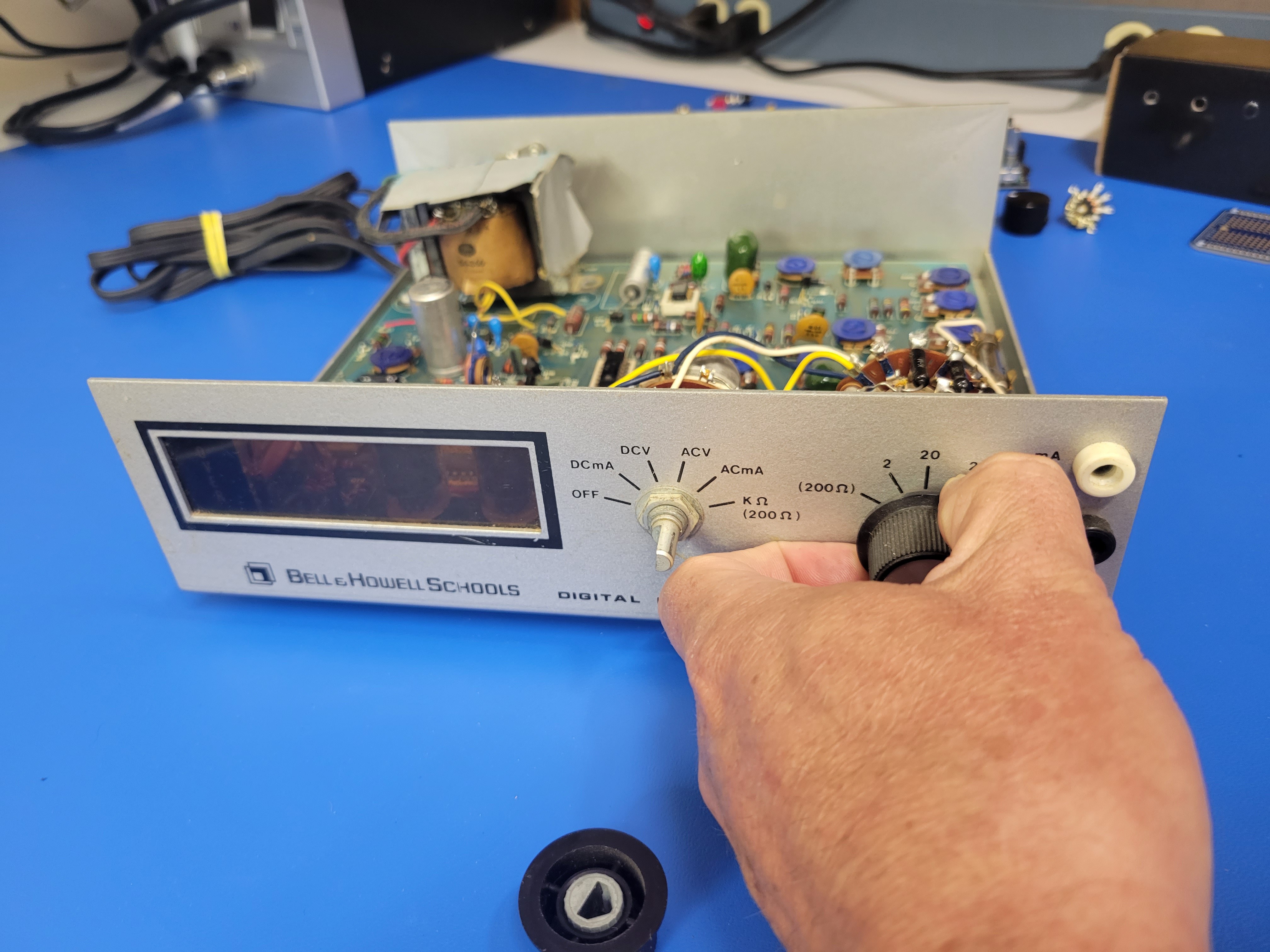
Next, you'll remove the rotary switched and banana plugs from the front. Start by pulling the knobs off.
![]()
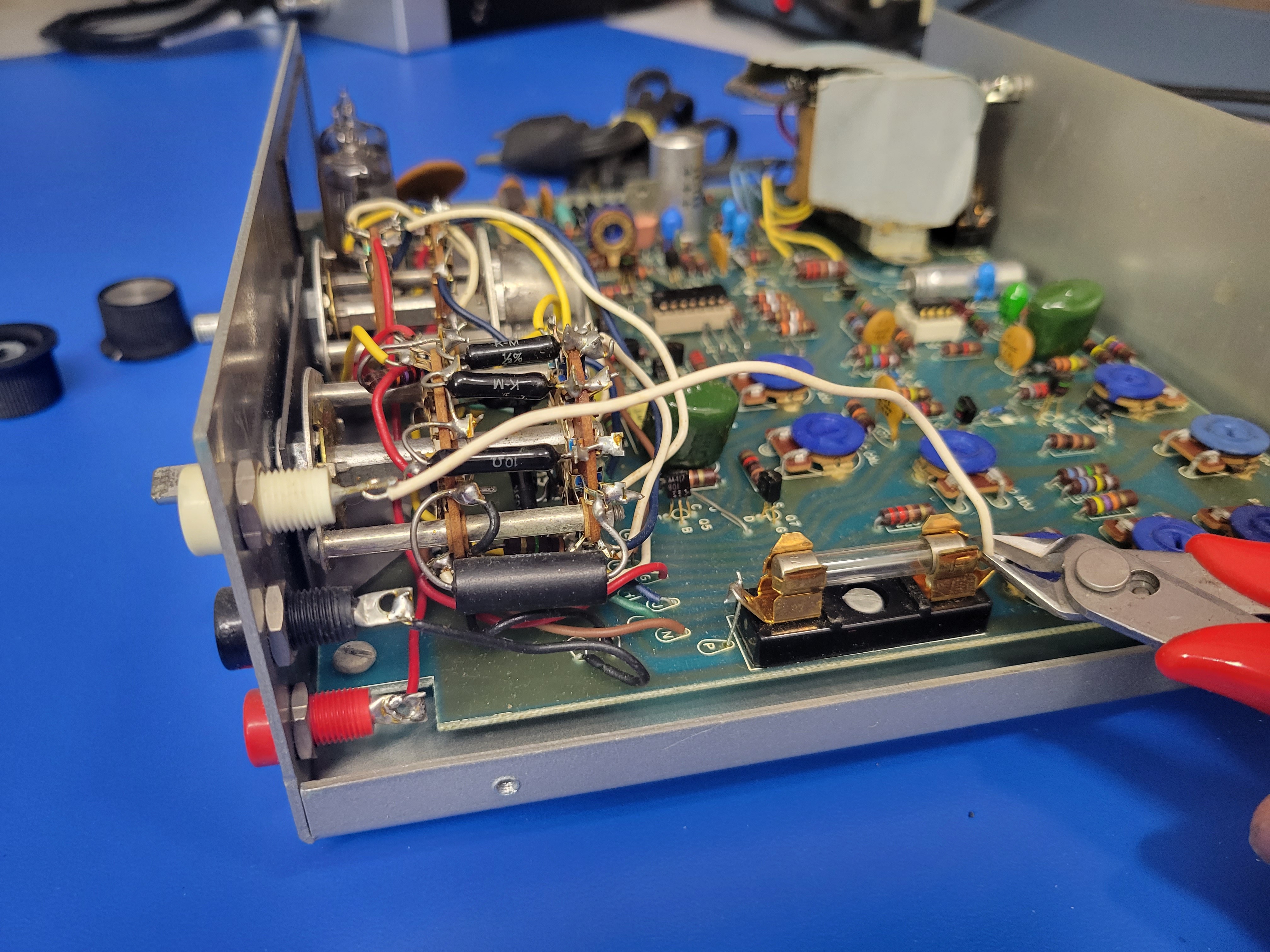
Then you'll cut the wires connecting the three banana plugs.
![]()
Note: the red plug is connected to the left rotary switch.
![]()
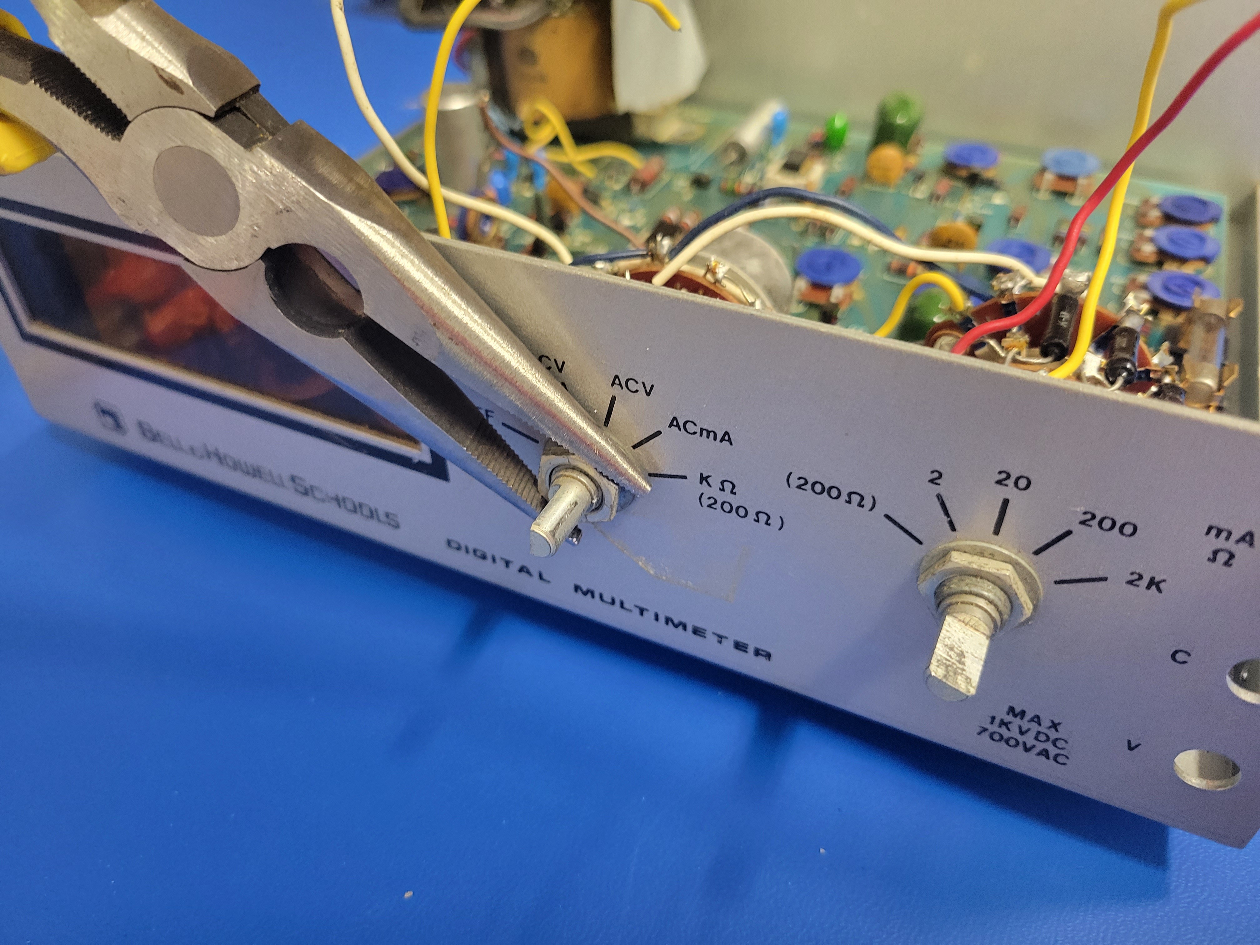
Now you can use a pair of needle nose pliers to loosen the nuts on the three plugs and remove them from the faceplate.
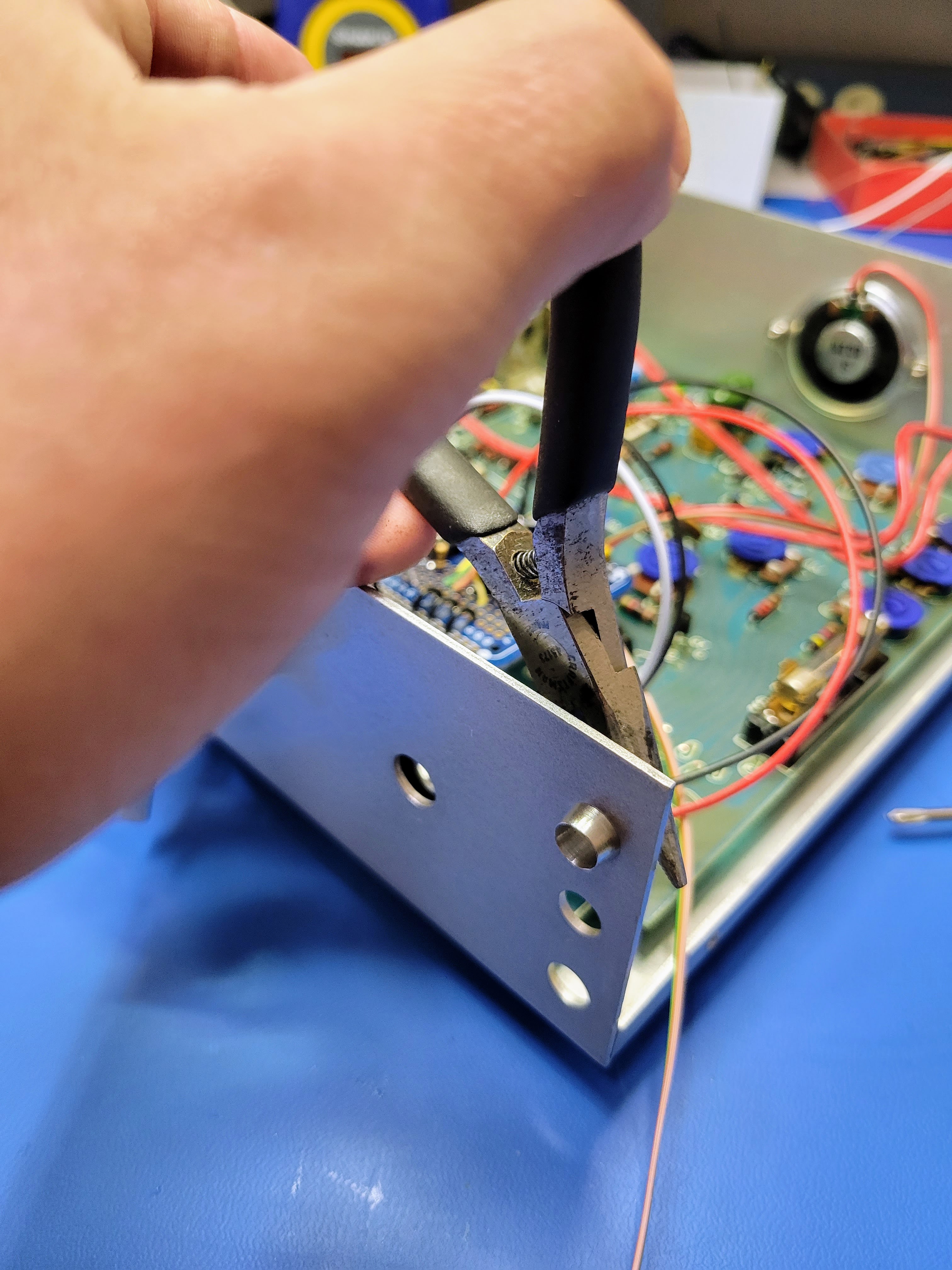
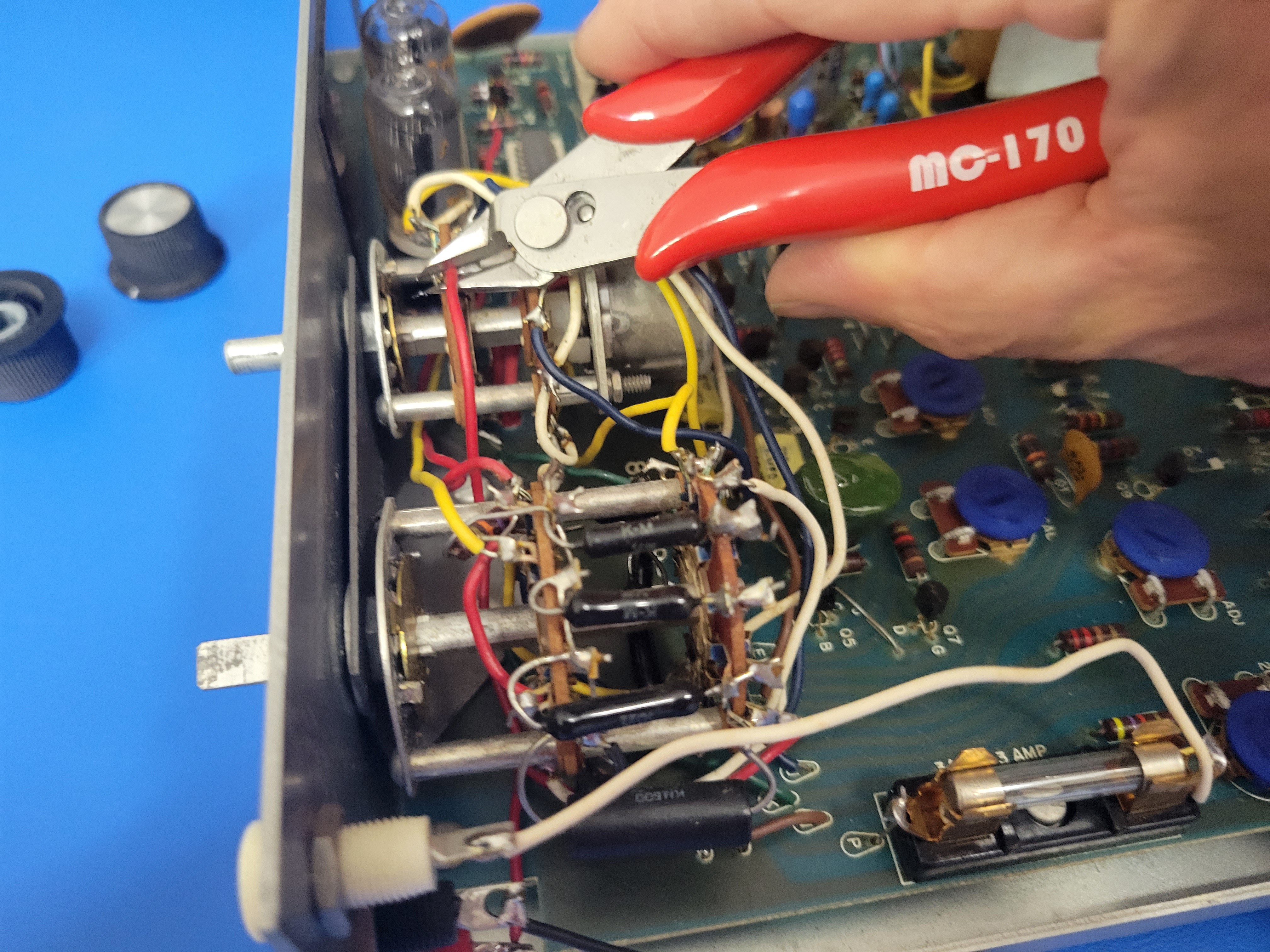
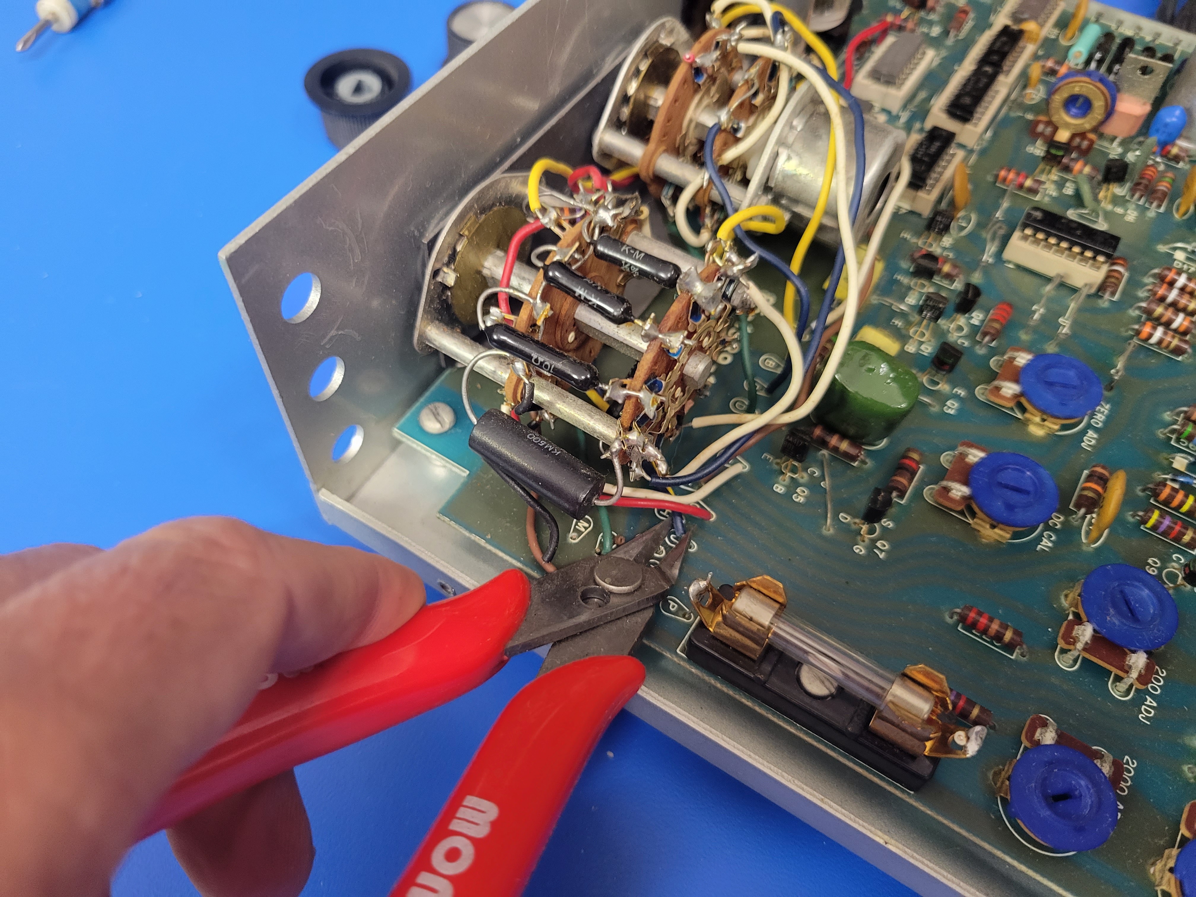
Next, cut the wires connecting the rotary switches to the PCB.
![]()
Don't forget the two wires connecting the rotary switches to the PCB just behind the nixies.
![]()
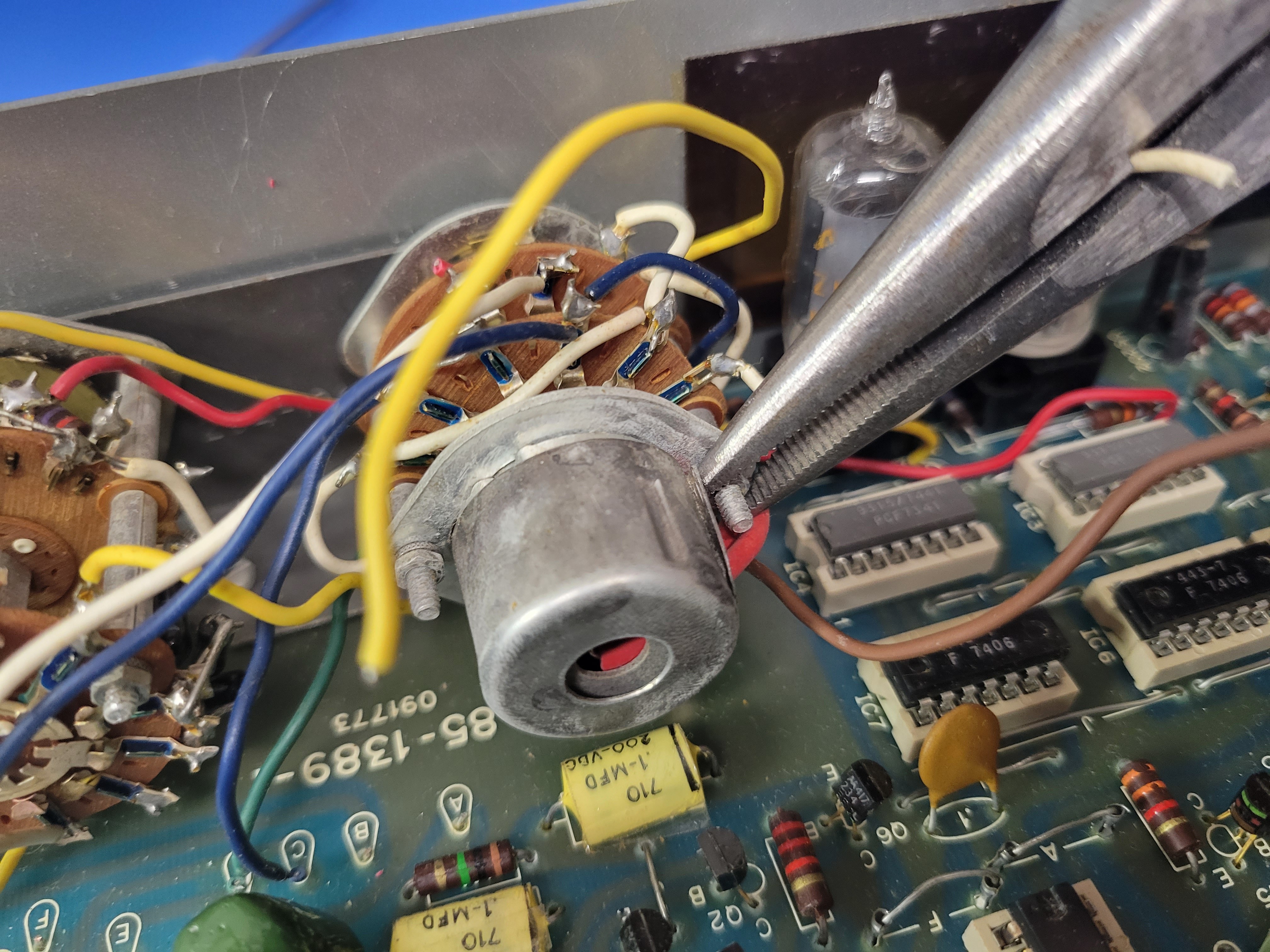
This cap will have to come off. A small flathead screw driver will work (ignore the needle nose pliers).
![]()
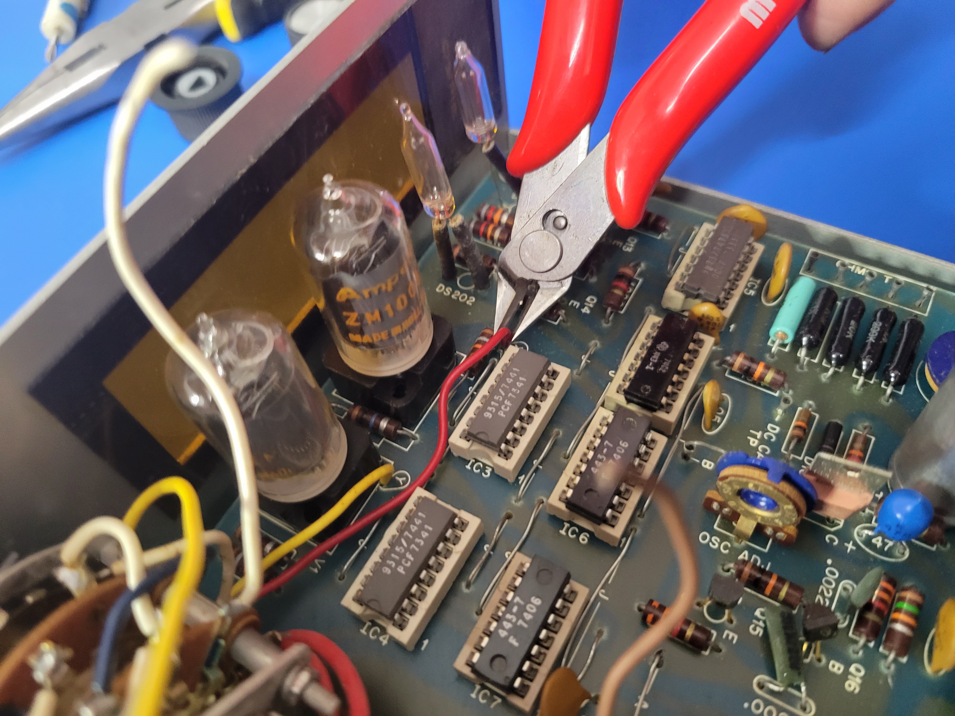
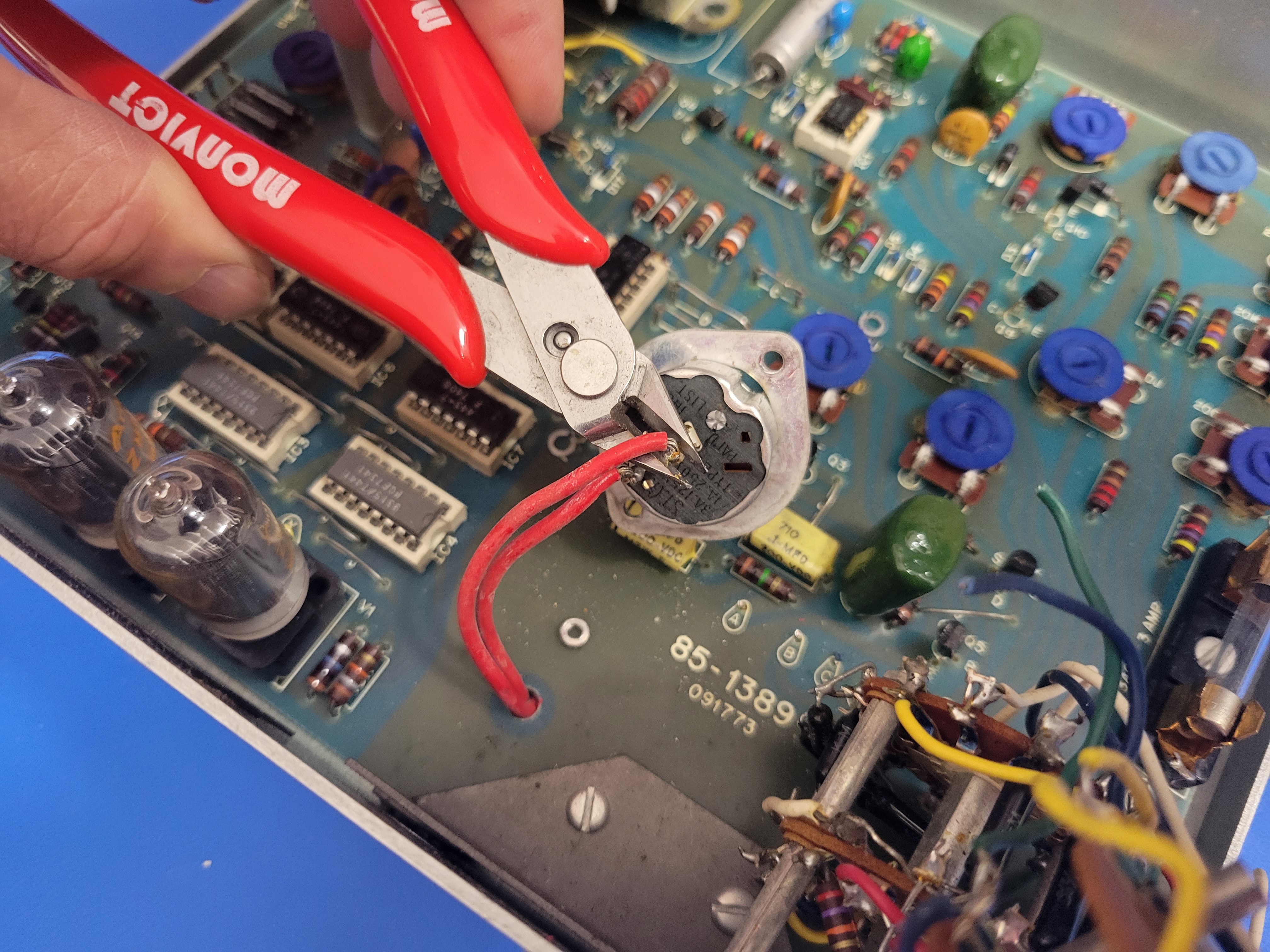
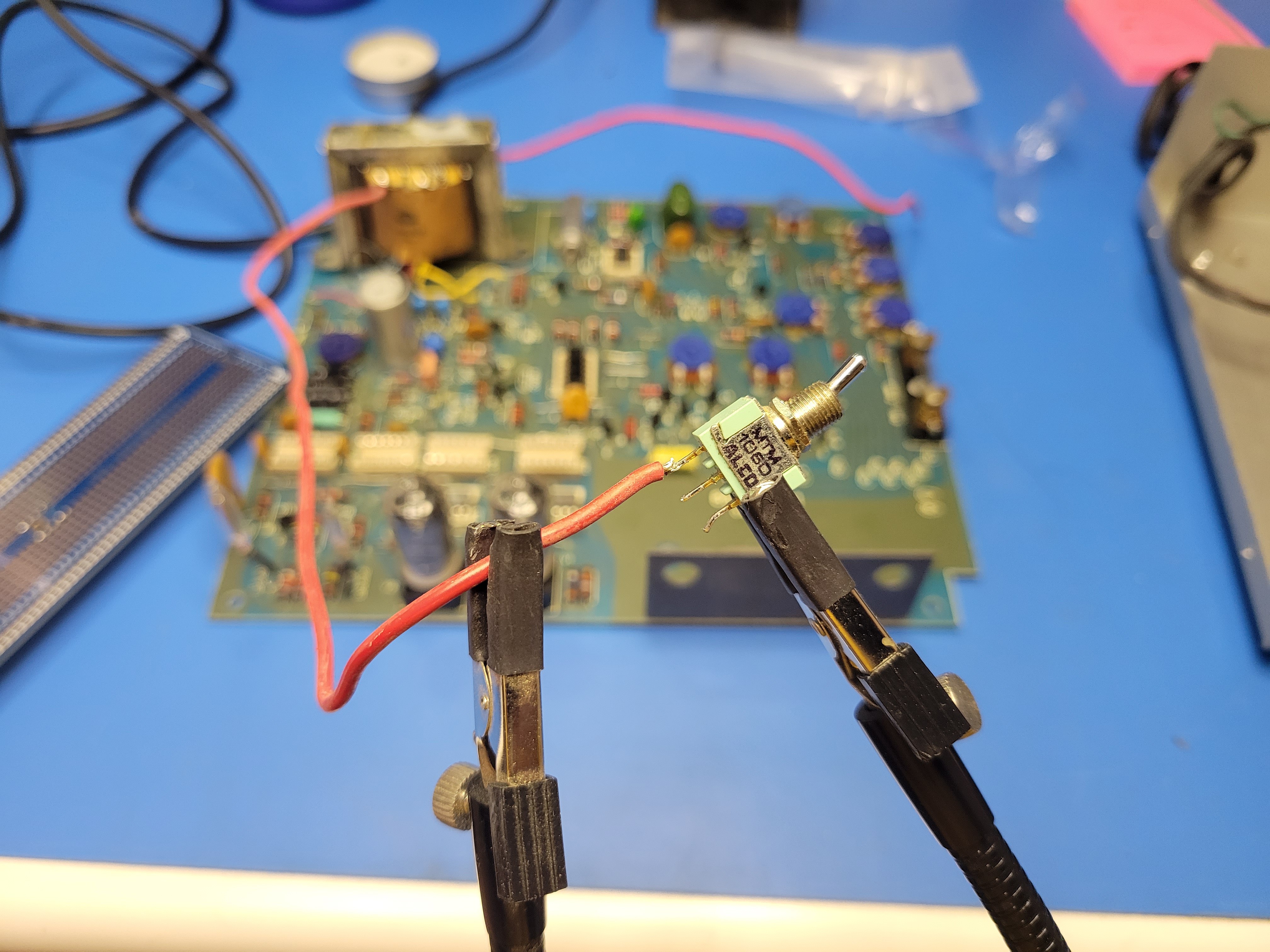
Once the cap is off, you can clip the two red wire off. You'll want to keep these wire as long as possible. In the pic below, I removed the on/off switch from the rotary switch before doing this. That is not required.
![]()
Now you can remove the rotary switches from the faceplate.
![]()
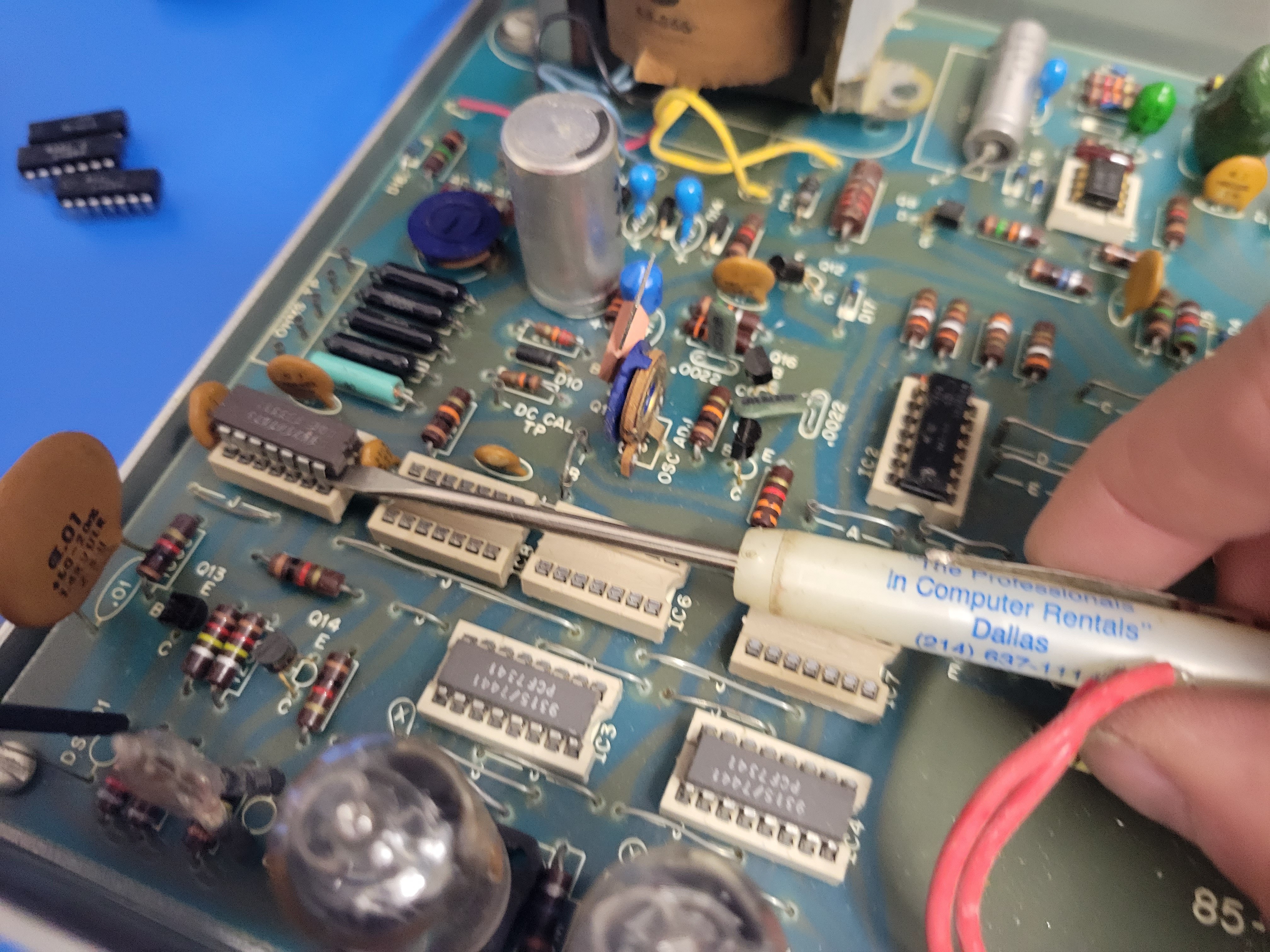
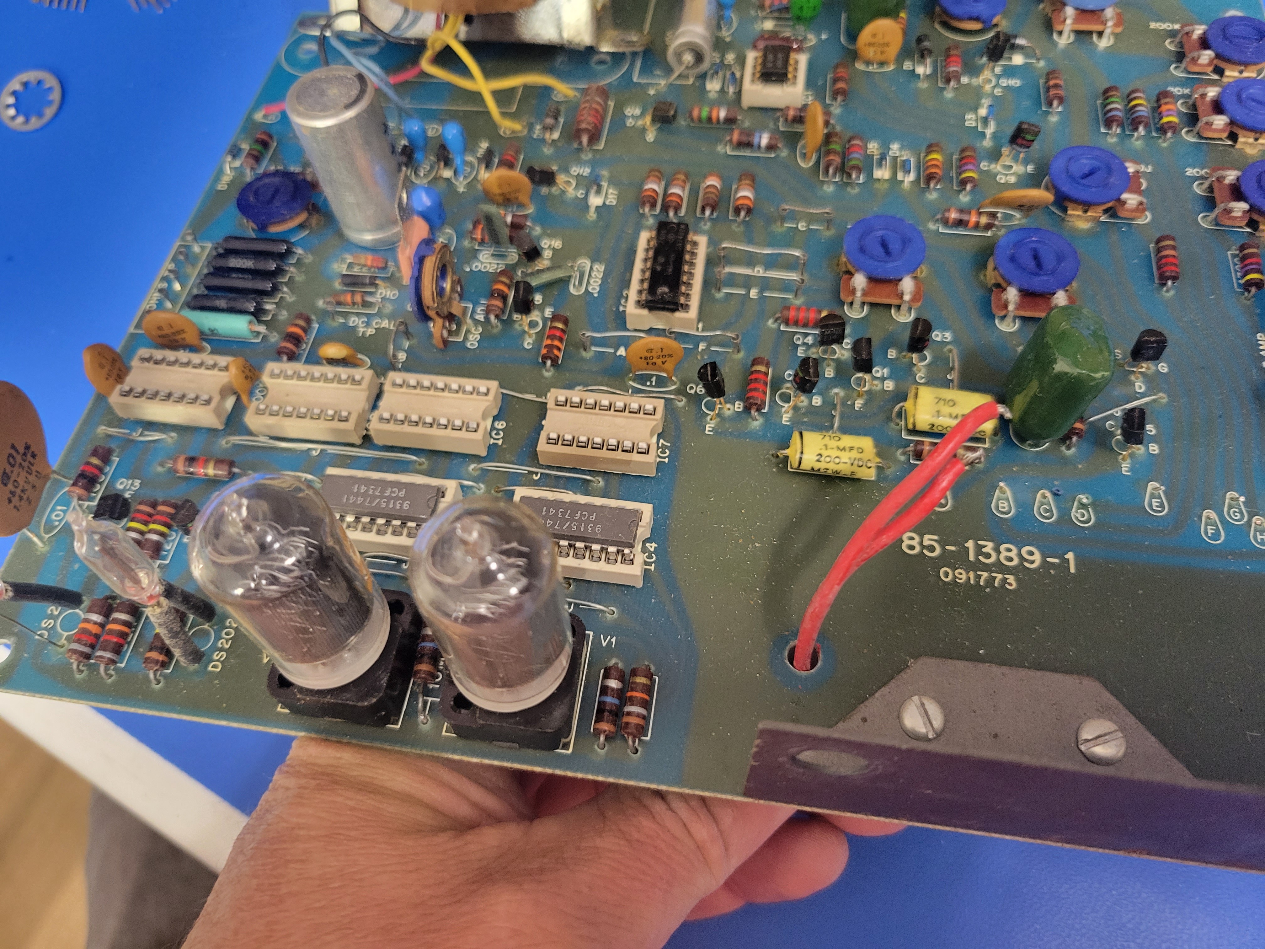
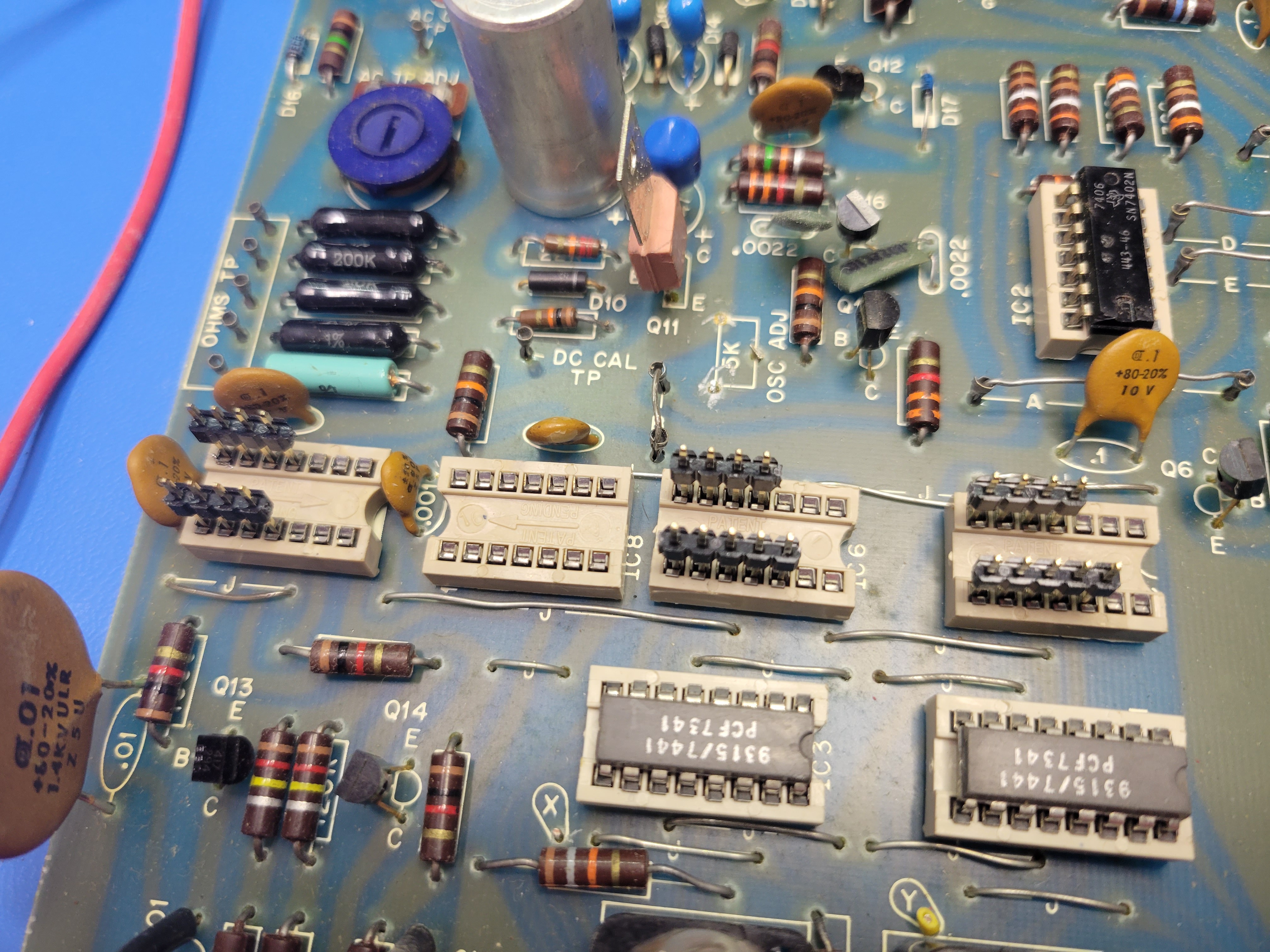
Then remove IC5, IC6, IC7, and IC8 from their sockets on the PCB.
![]()
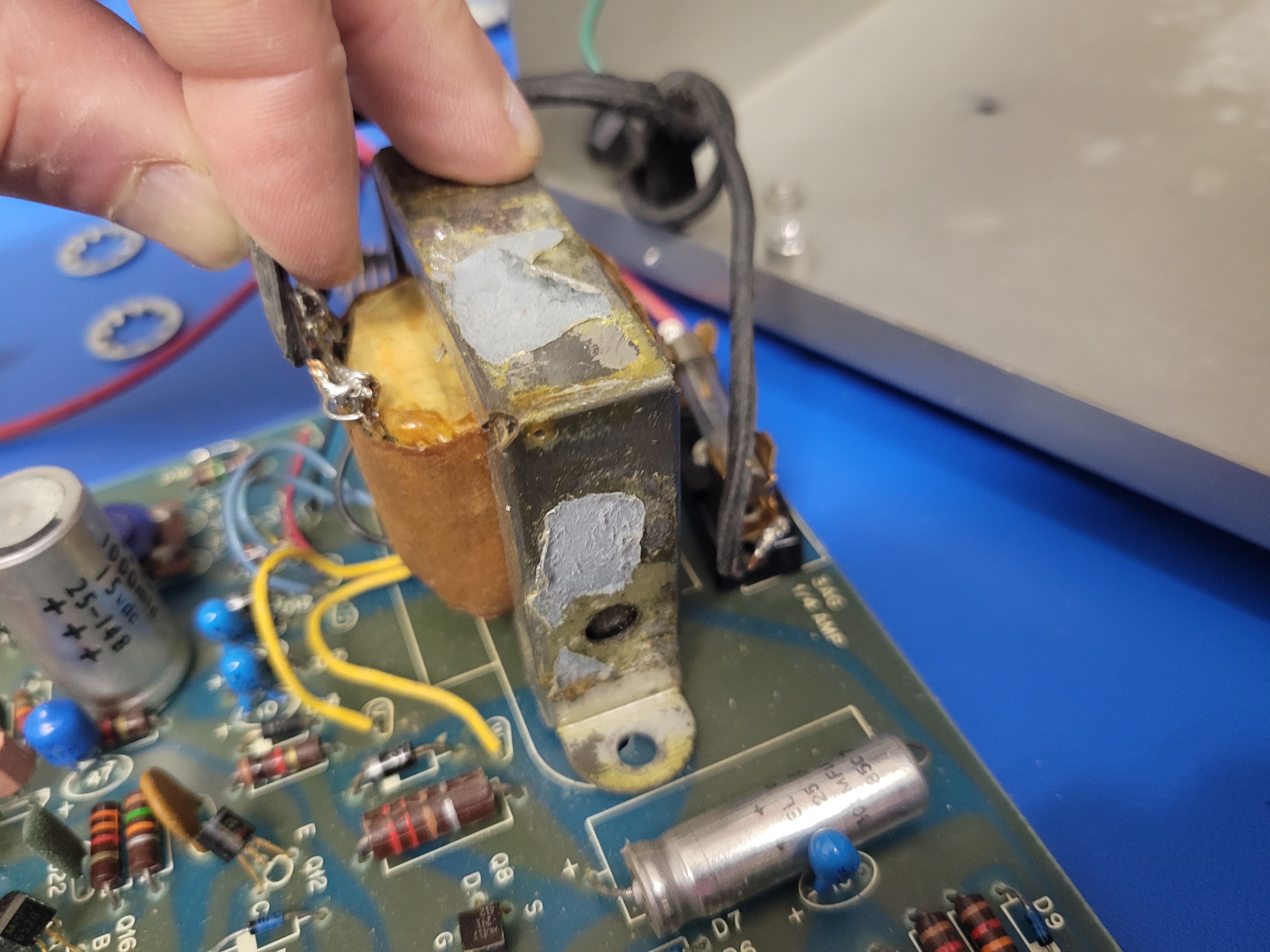
Now it's time to remove the PCB from the base of the case. Remove the 5 screws holding the PVB to the standoffs mounted to the case. Three are on the front left, front right, and rear right corners. The other two hold down the transformer.
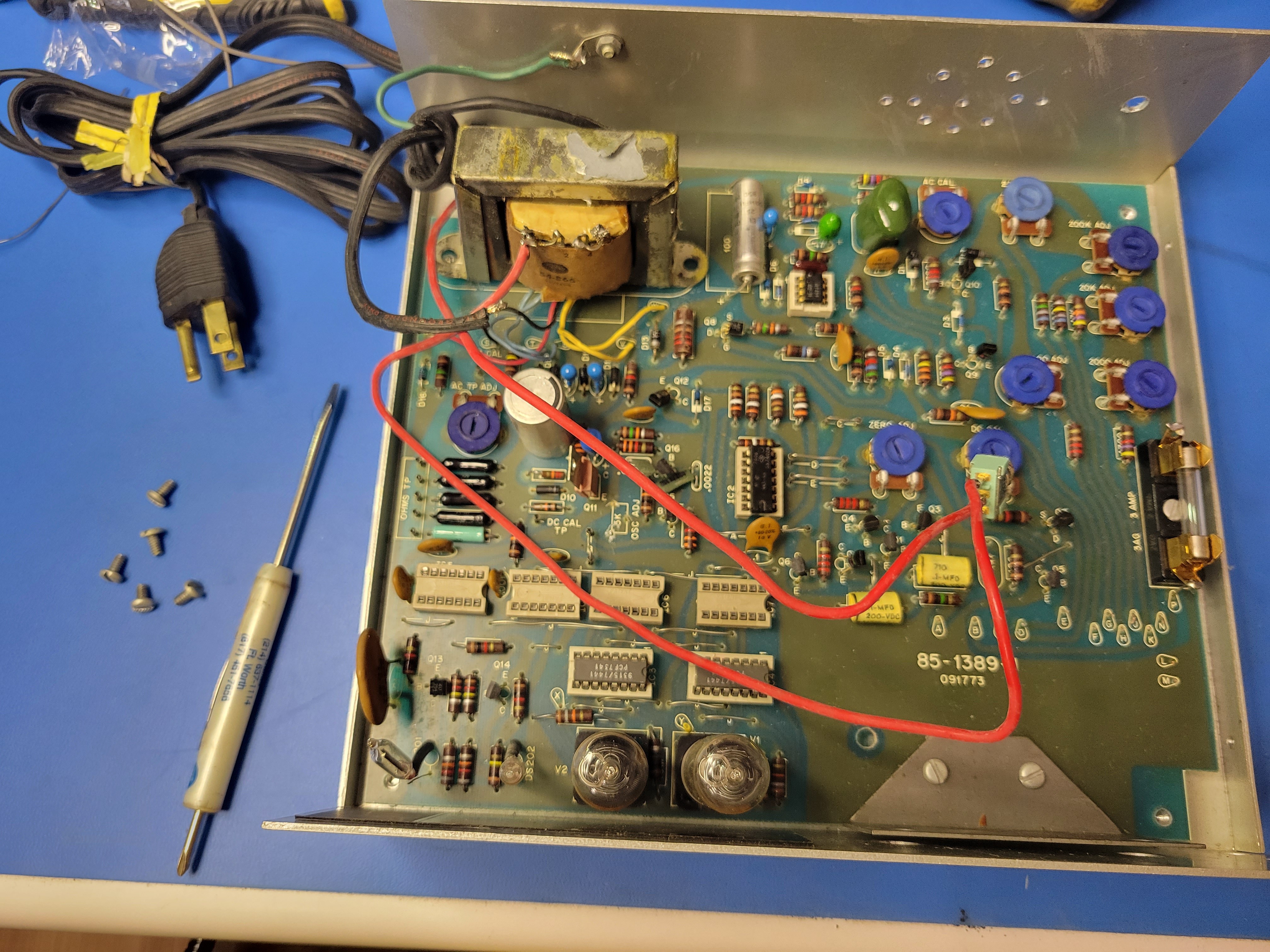
![]()
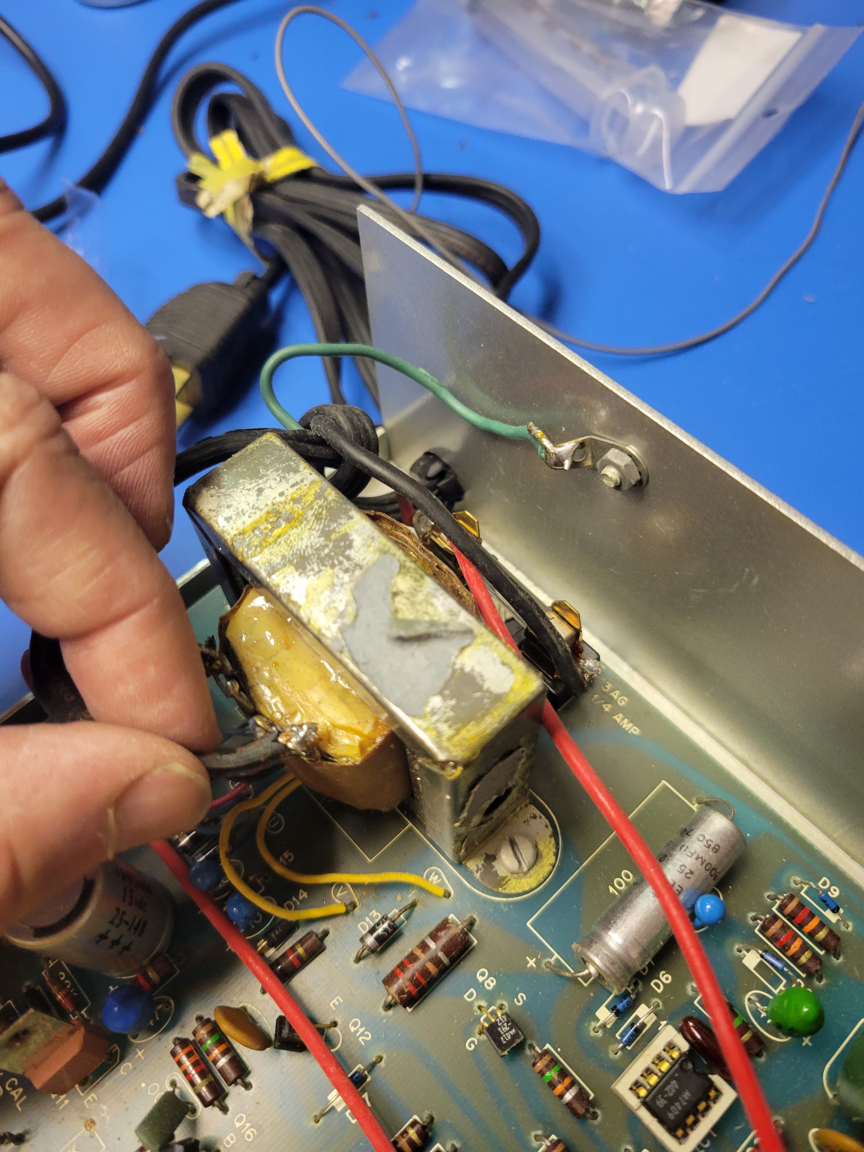
Once the board is free, pull the to red power wires through the board and lift it up. You will use these red wires to turn the device on and off. So leave them intact and soldered to the boars. The PCB will still be connected to the power cord in the rear at the transformer and fuse. You will need to clip these connections to the power cord at the soldered connections.
![]()
![]()
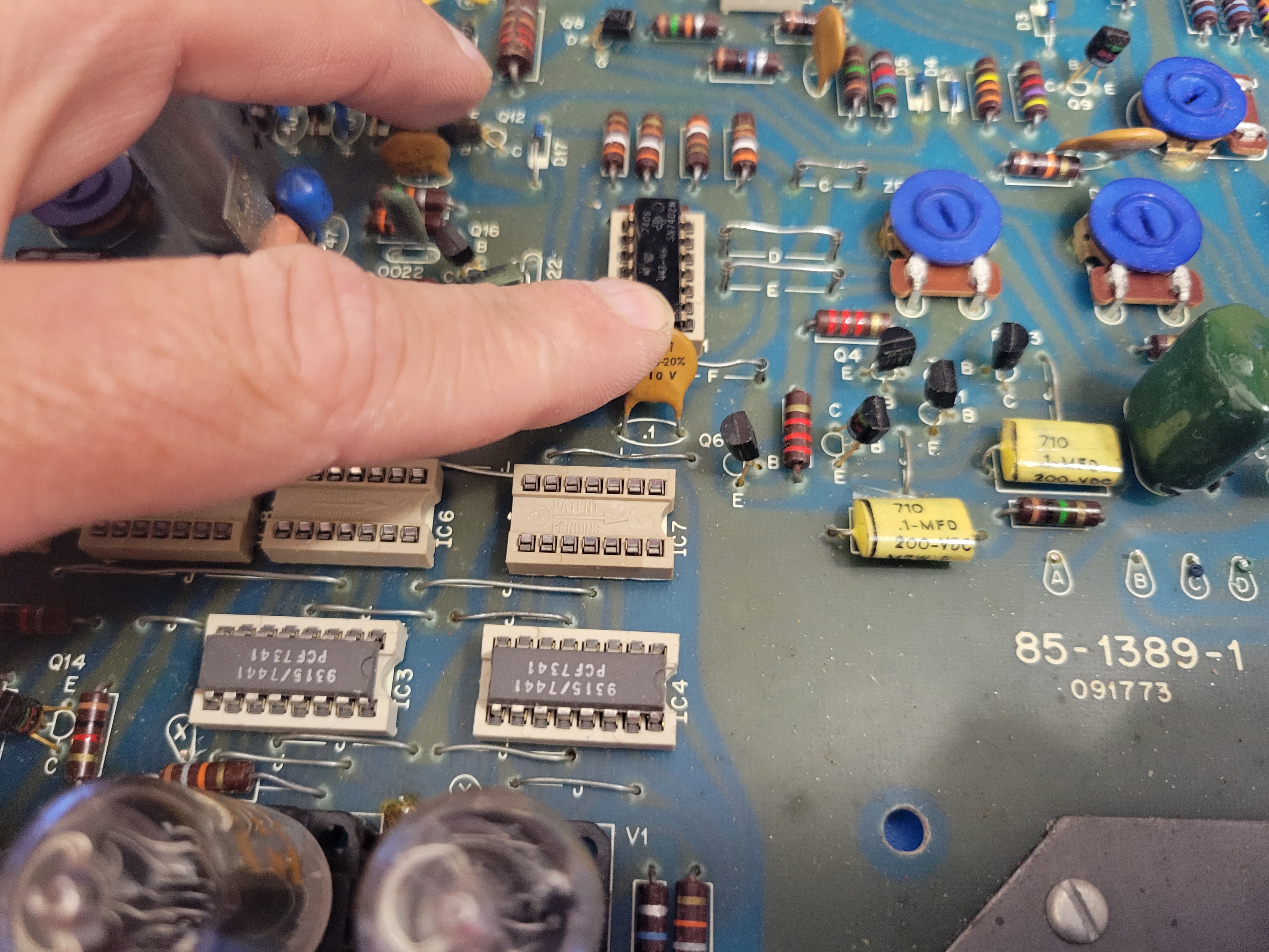
Next you'll make some room for the controller board. Start by pushing this cap behind IC7 down and out of the way for the controller board.
![]()
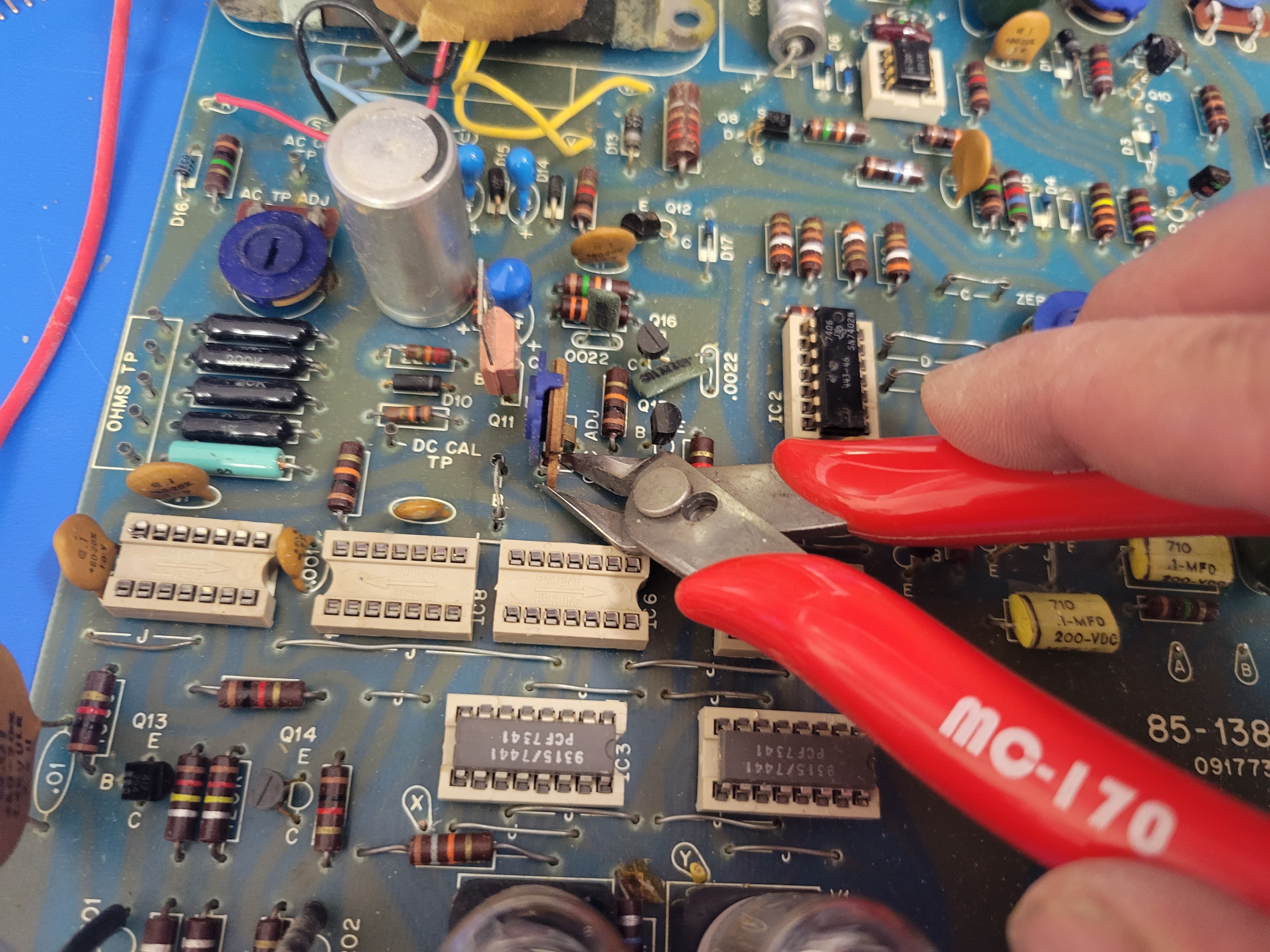
Then clip and remove the pot behind IC6.
![]()
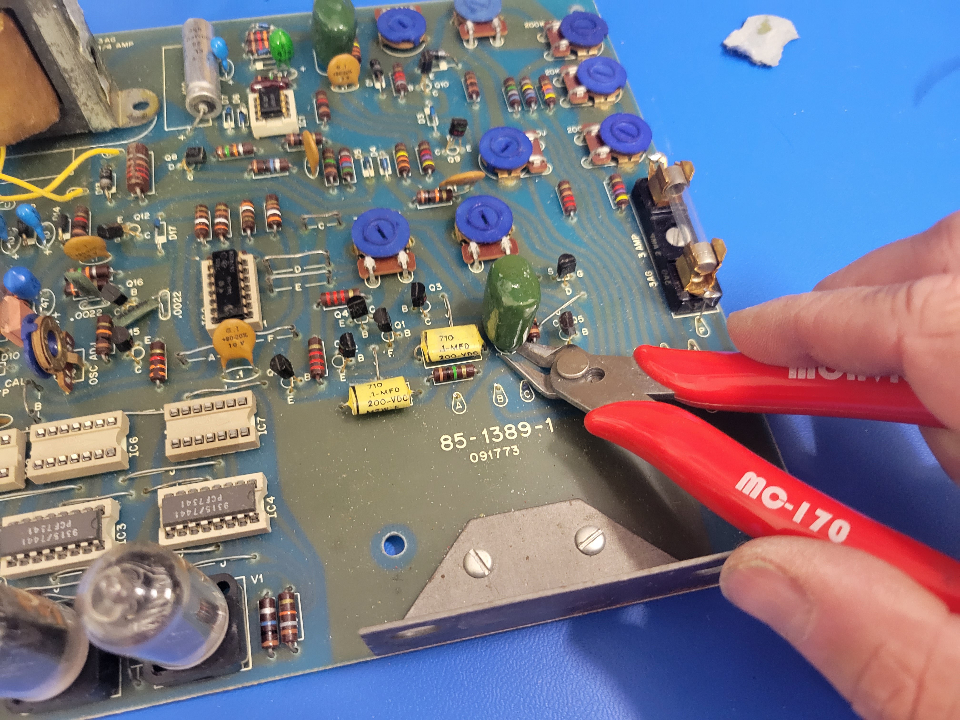
And clip/remove the large green capacitor behind the rotary switches (at least where the rotary switches were).
![]()
The final step of making room for the controller board is grinding/filing a little off the edge of the controller board so it will clear the large ceramic on the far left side of the board. Be careful not to file or grind into the wire trace that connects the power busses.
![]()
Now it's time to install some headers and fit the controller board in place on the PCB. The controller board will need to be connected to the sockets for IC5, IC6, and IC7. IC6 and IC7 are 7490 decade counters that controlled the digits displayed on the nixies. So, they provide the 4 pin interface to select the digit displayed on the corresponding nixie. They also provide the 5v and ground needed to power the controller board. IC5 will provide the interface to the one hundreds digit and the overflow indicator.
![]()
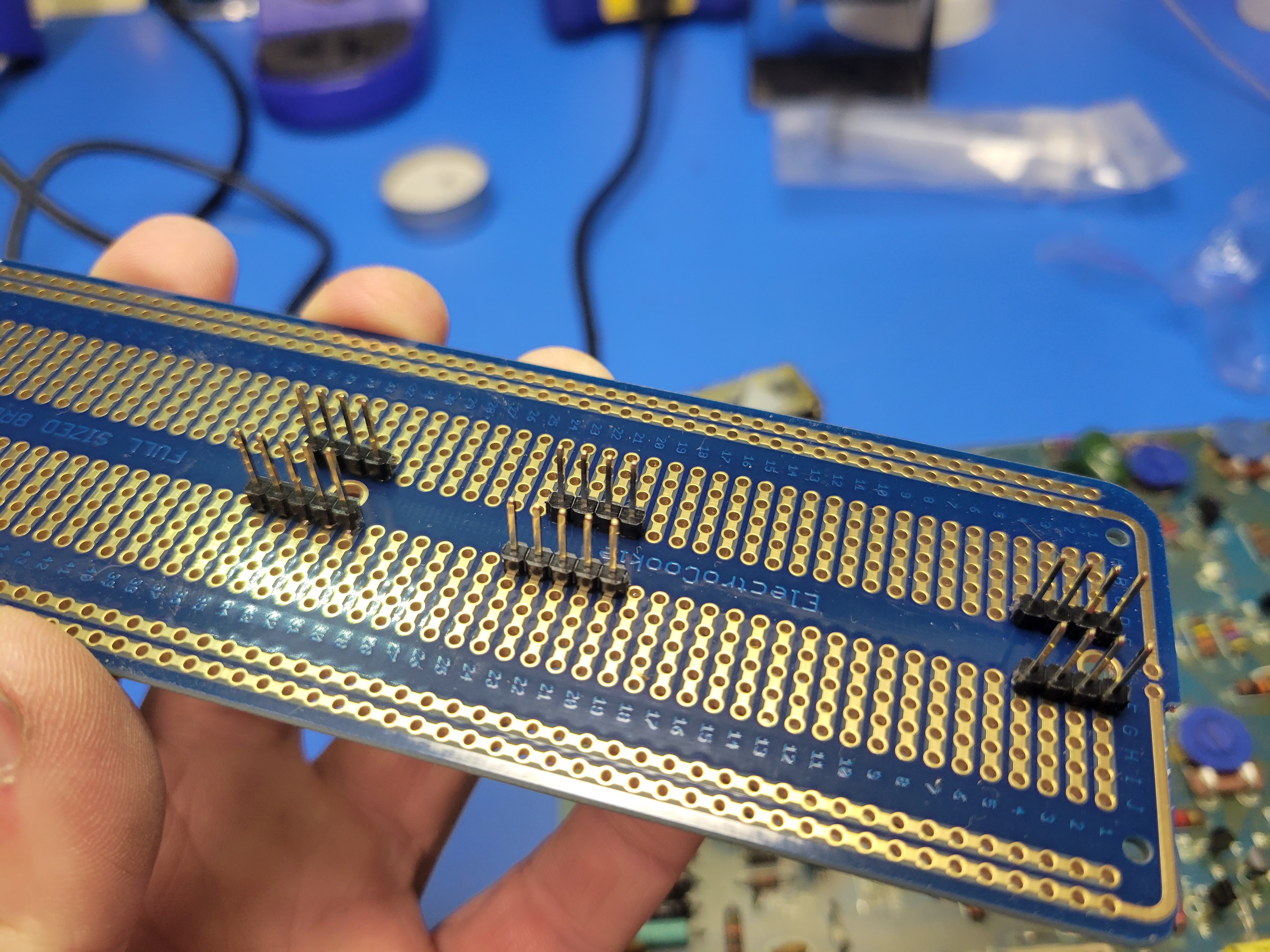
Cut and insert 2.54 mm single row headers into the sockets for IC5, IC6, and IC7 as shown in the picture. Note: these headers are longer on one side (6 mm vs 3 mm). Insert the long side into the socket.
![]()
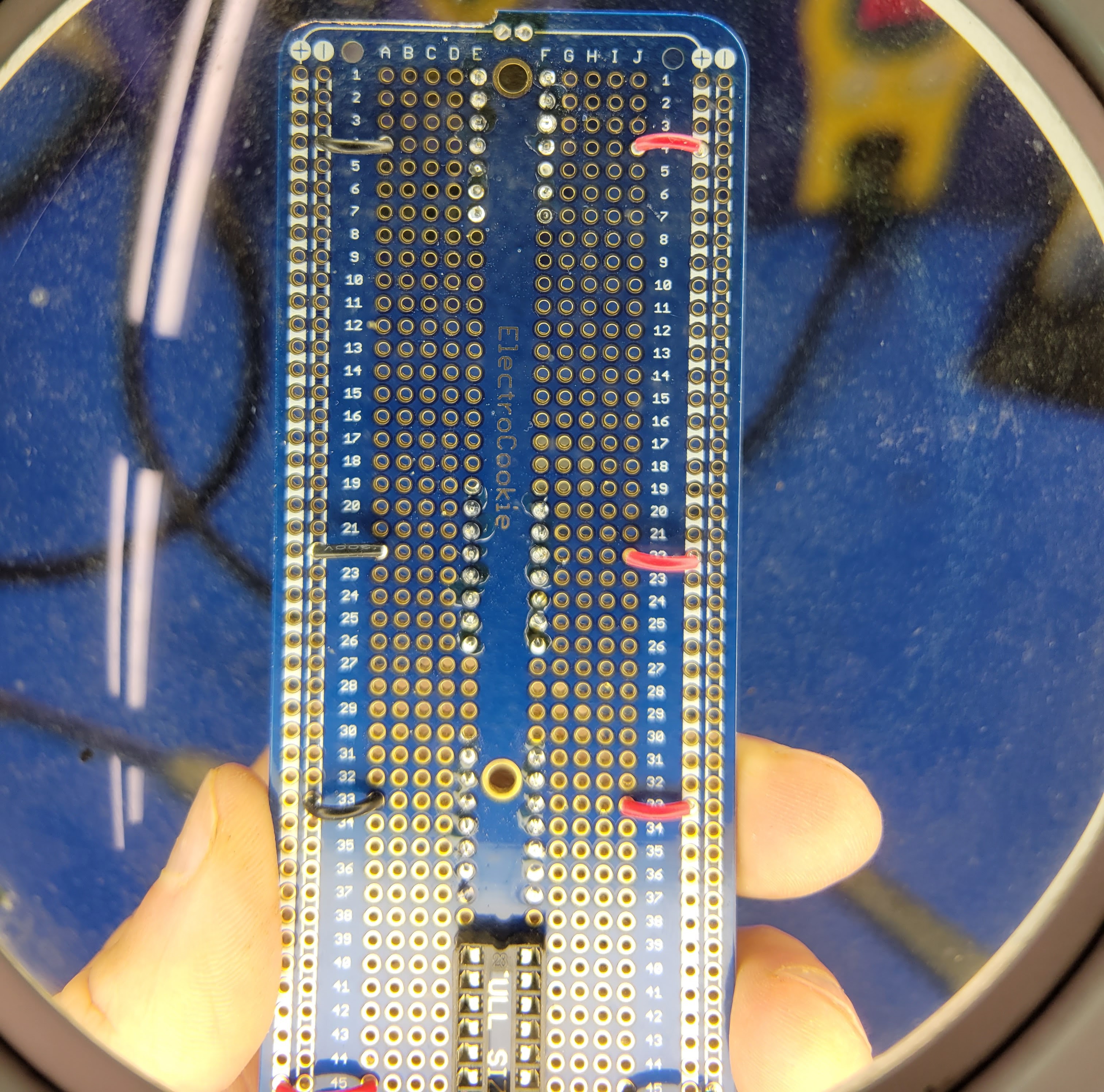
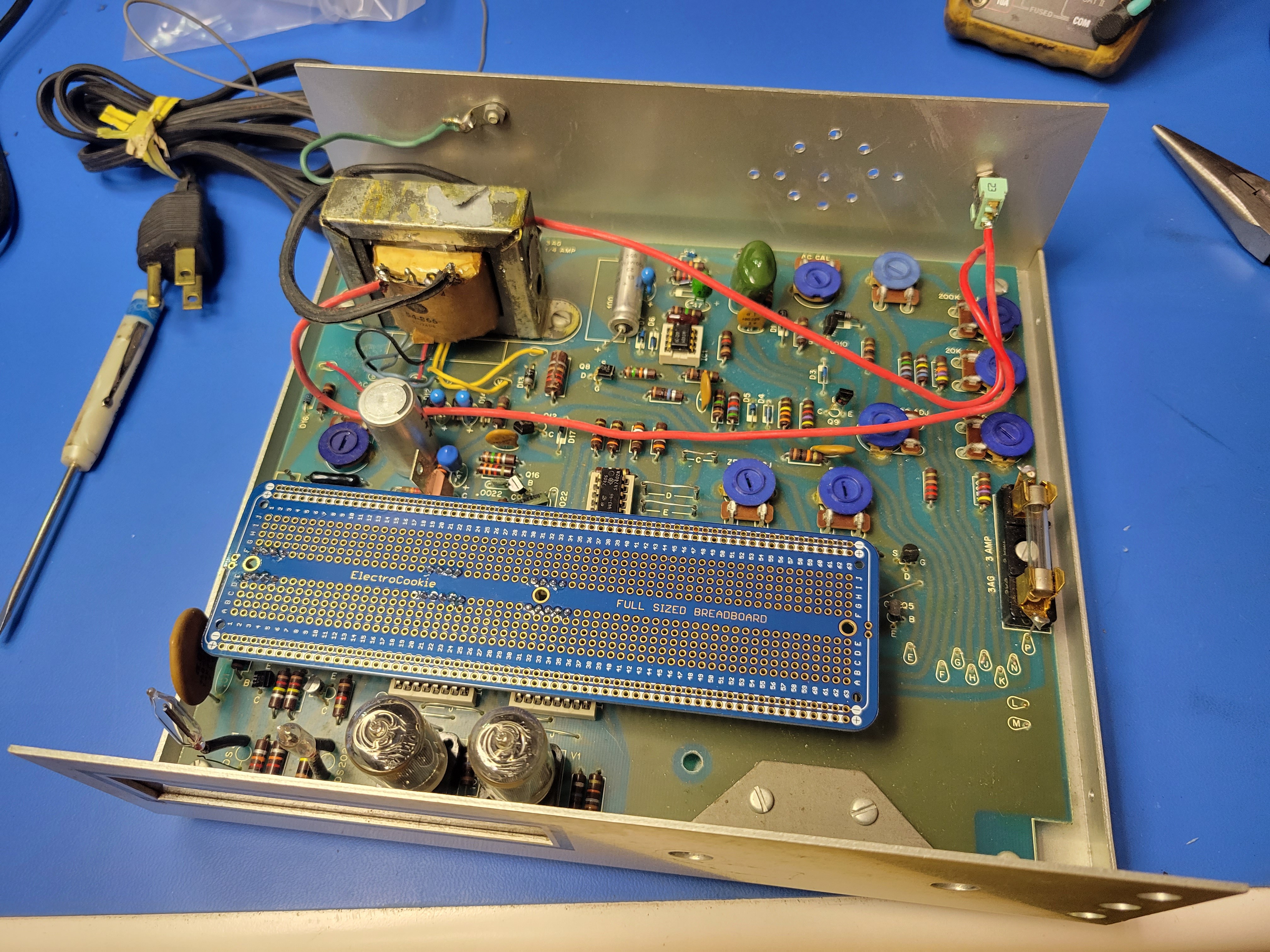
This is the hardest part of the build. You will have to line up the headers so they fit into the breadboard with the left most pins fitting into row 1 of the board. It should look like this once you get it lined up and in place. Look closely, you can see the pins poking through.
![]()
Now with the breadboard still in place on the headers plugged into the sockets on the PCD, solder the headers to the breadboard. It should look like this when you are done.
![]()
When you pull the breadboard out and flip it over it should look like this.
![]()
Next you'll modify the base of the case to mount a speaker and a toggle on/off switch. I suggest installing these in the rear for the case.
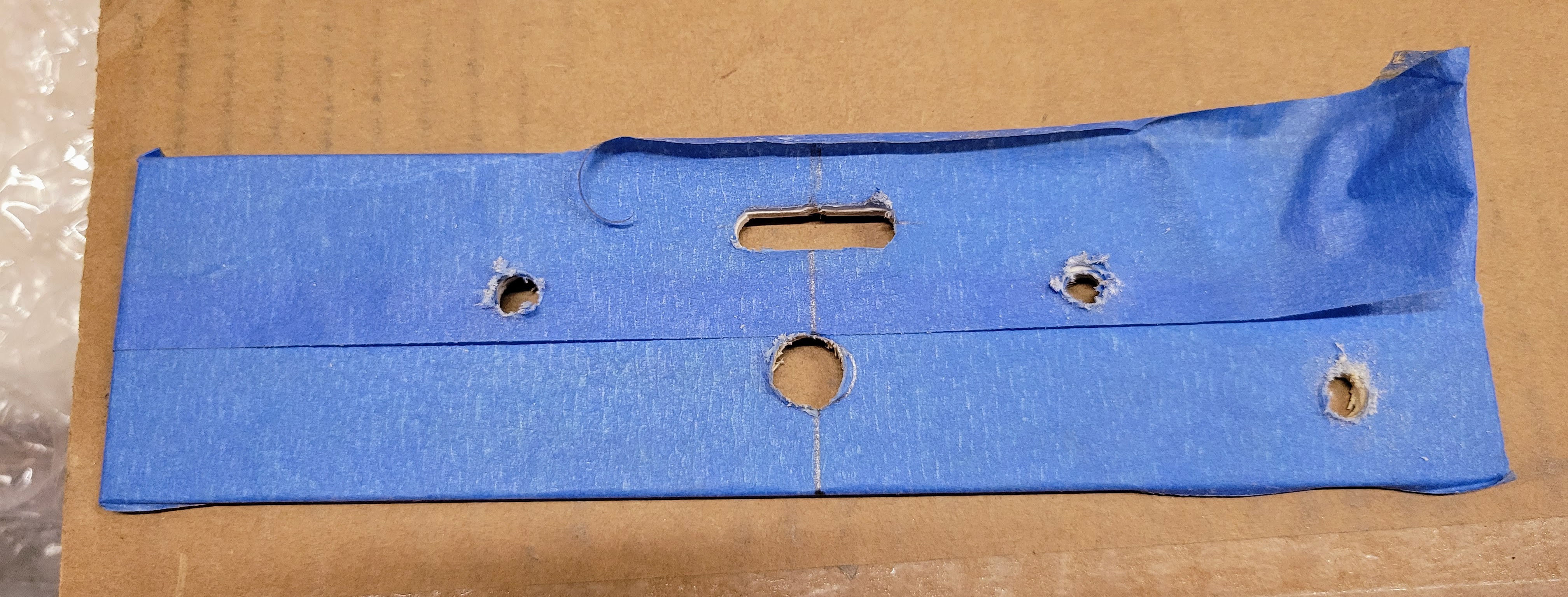
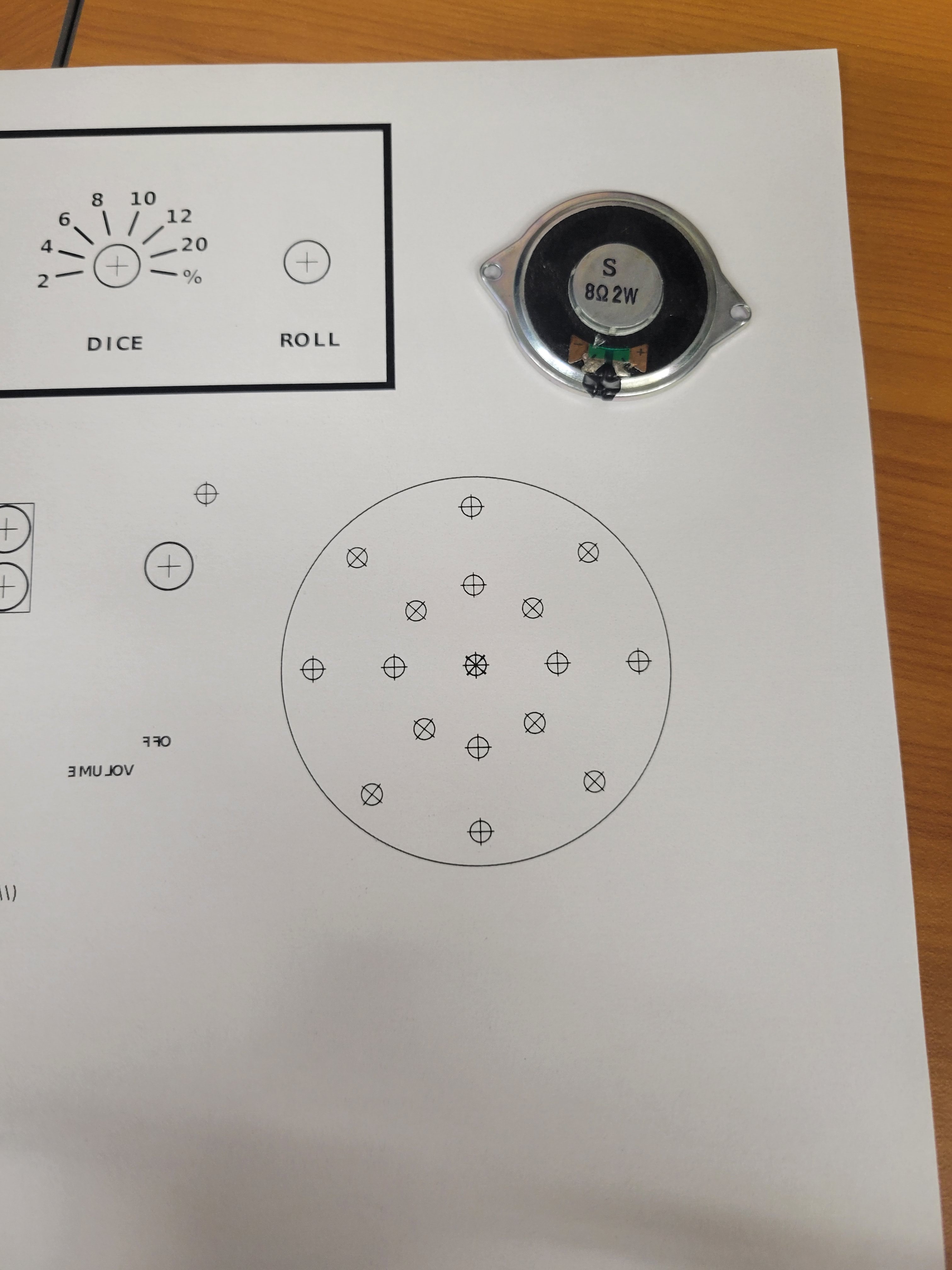
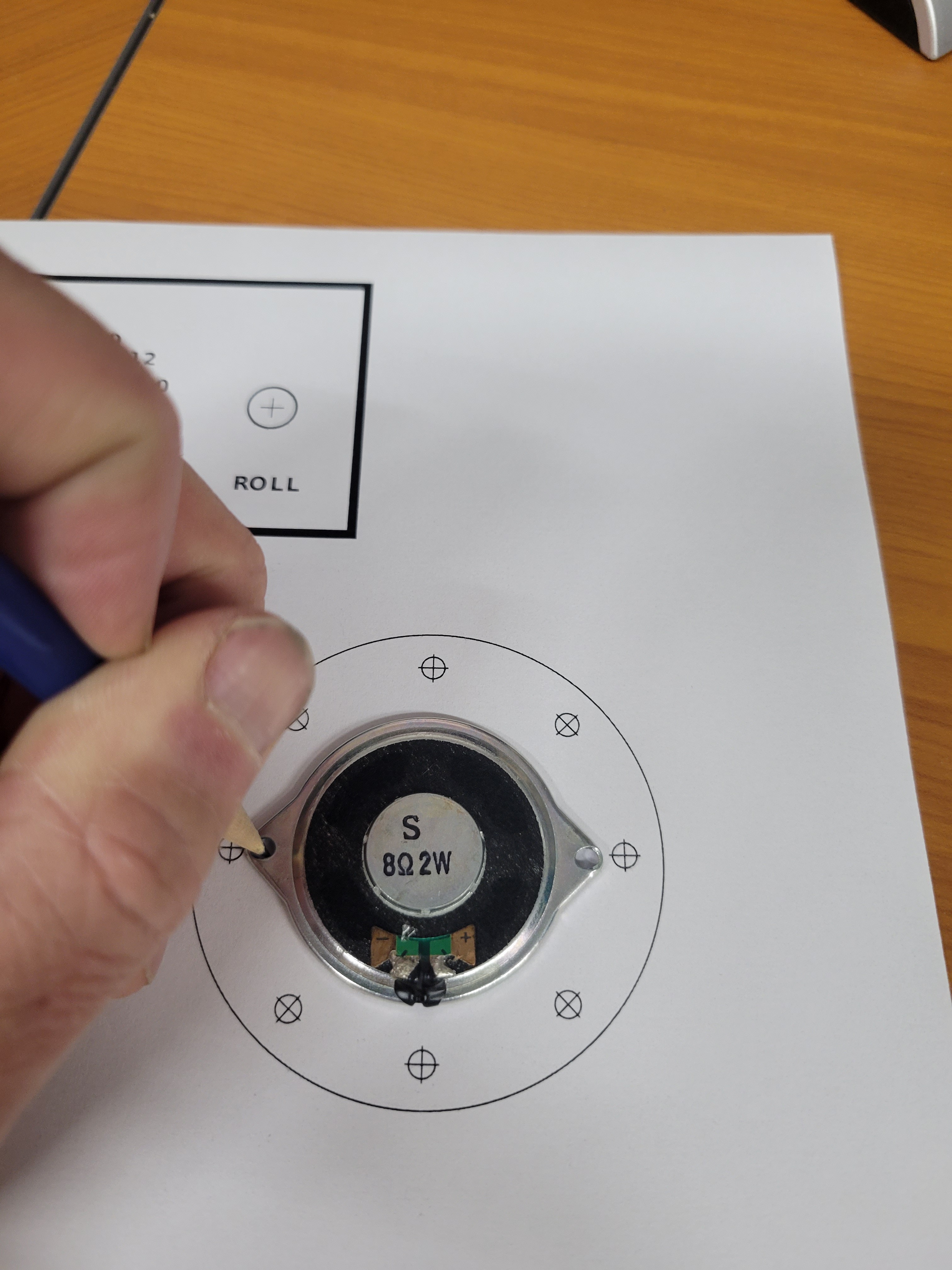
Start by creating a template for the speaker holes the allow the sound out and the holes to mount the speaker. Then print this template, cut it out, and tape it to the rear faceplate of the case.
![]()
![]()
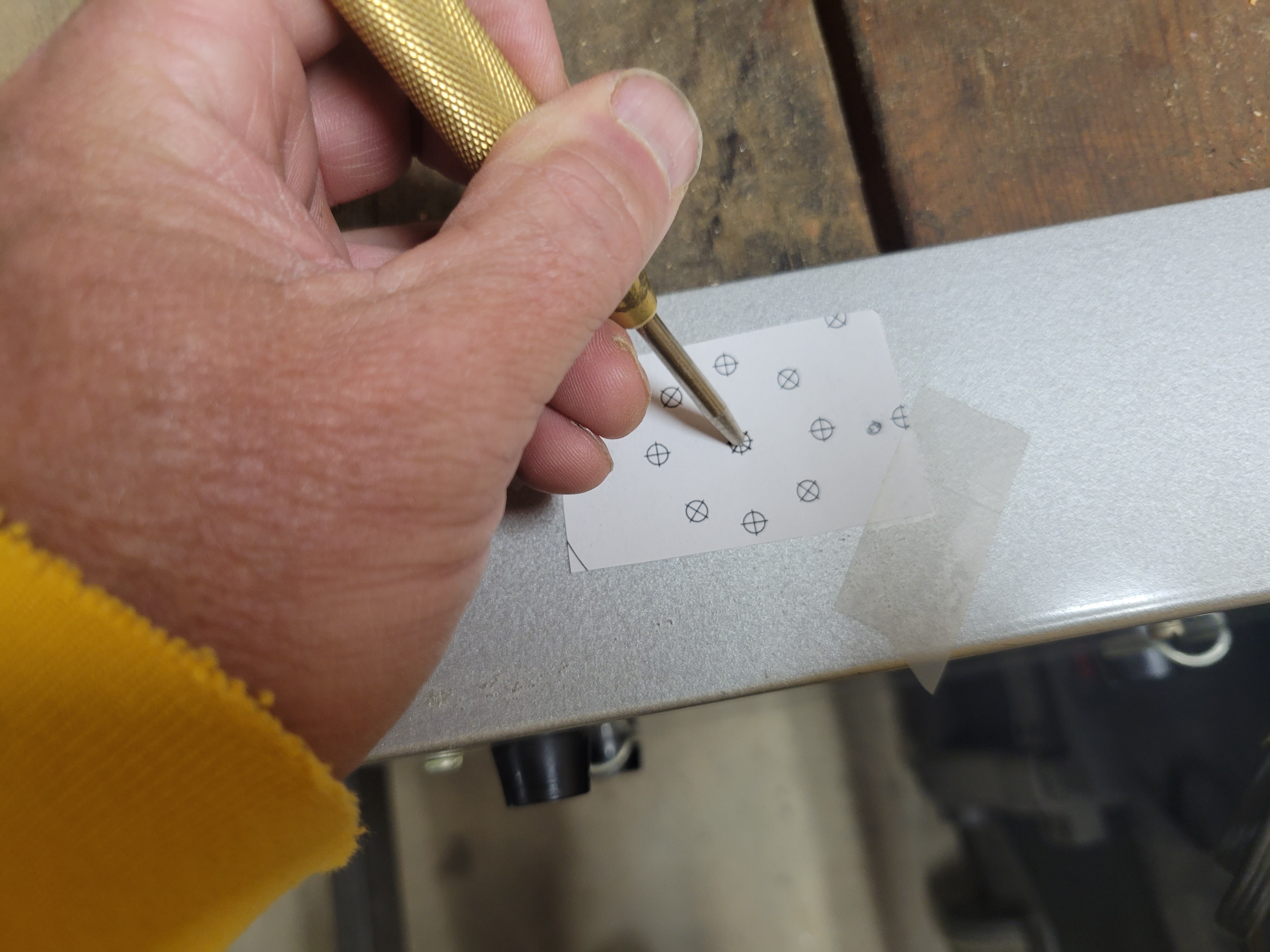
Next, you'll use a punch to notch the locations you will drill holes.
![]()
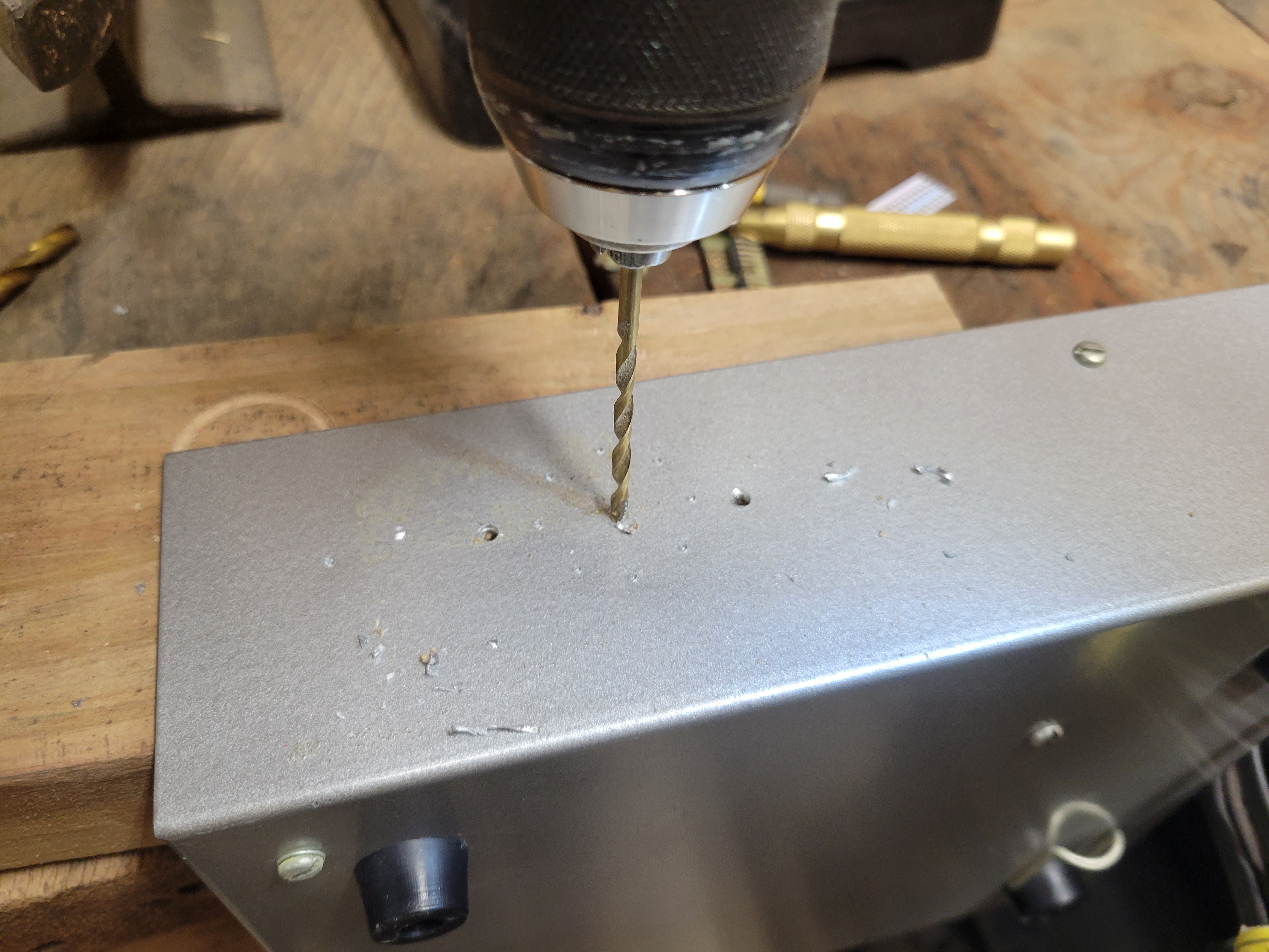
Remove the template and drill the holes. For my install, I drilled 1/8" holes for the speaker sound and mount. And, I drilled a 1/4" holes to mount the on/off toggle switch.
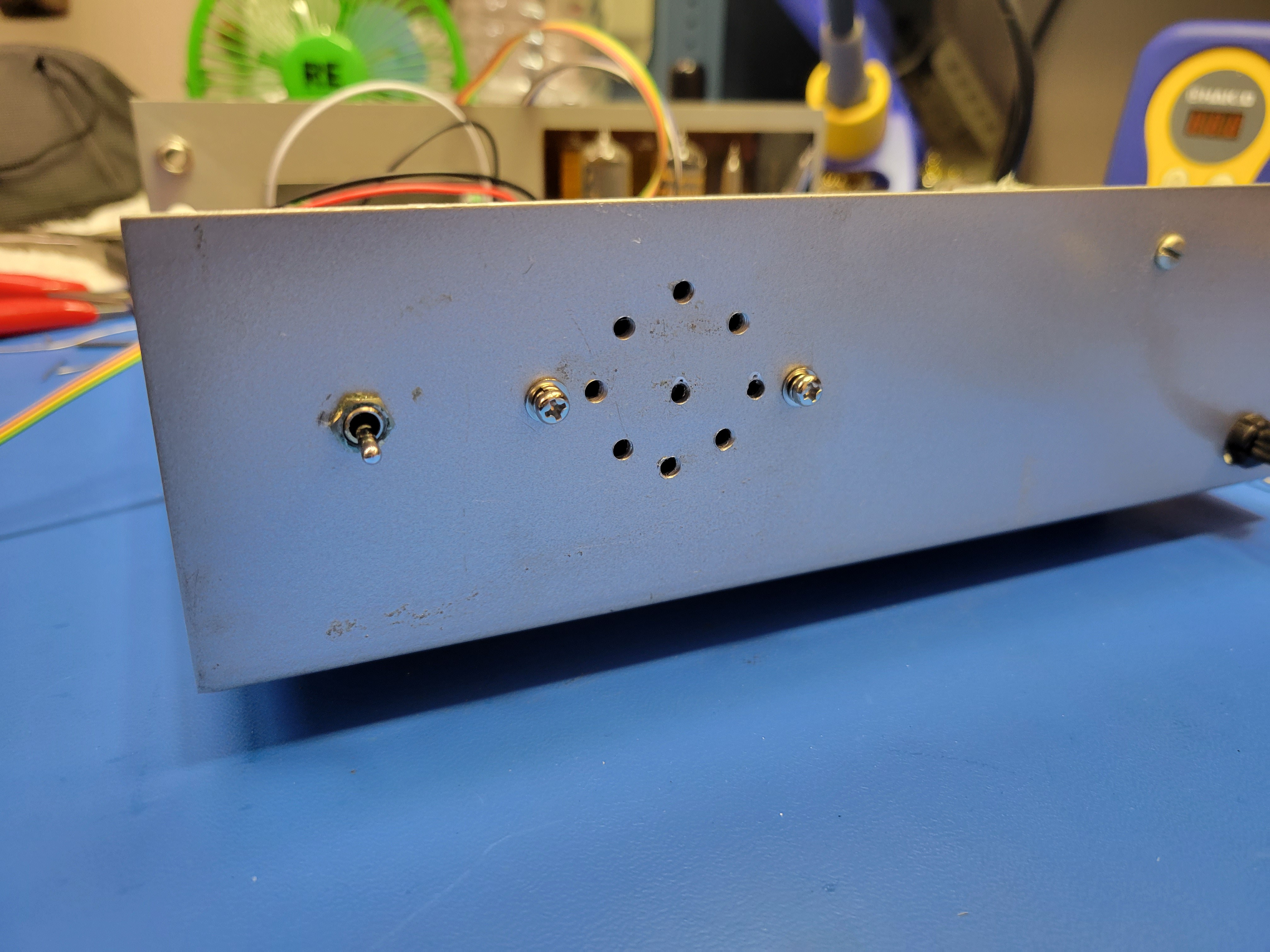
![]()
![]()
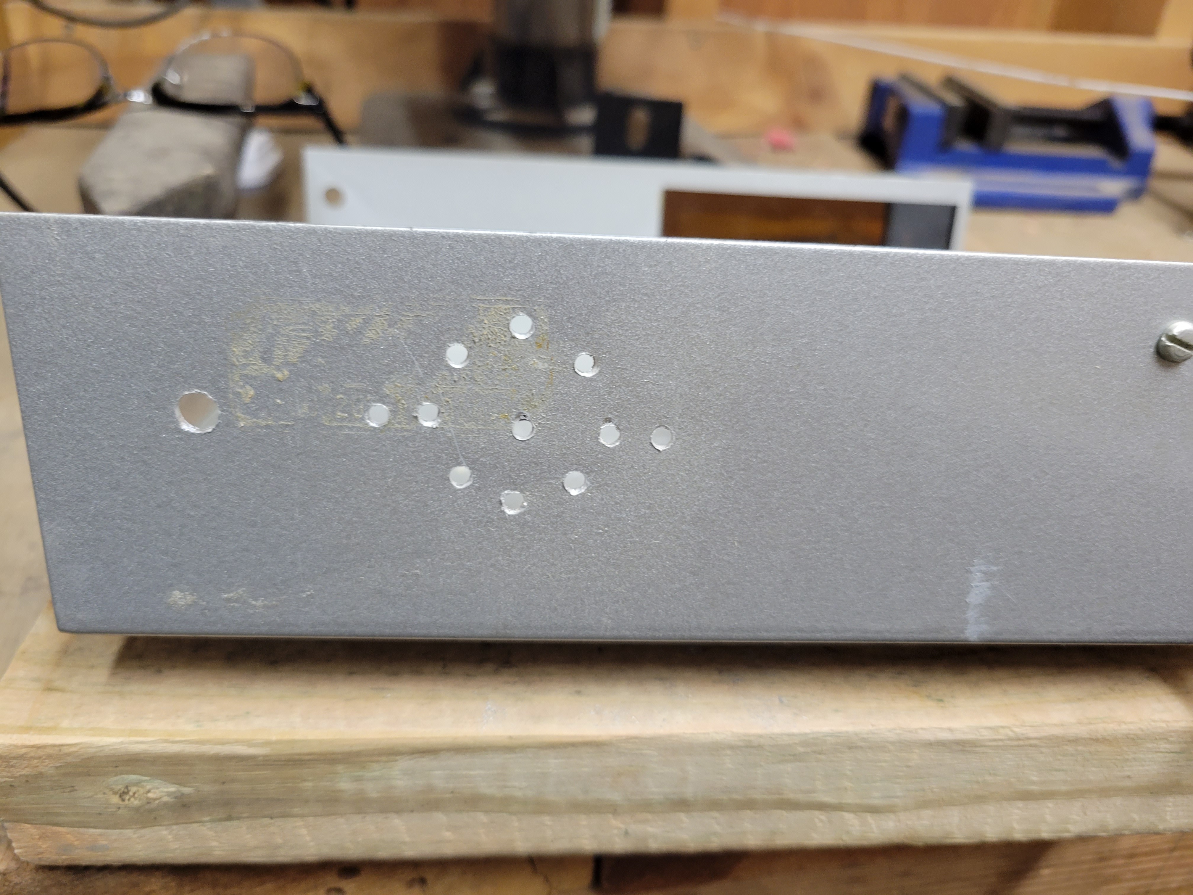
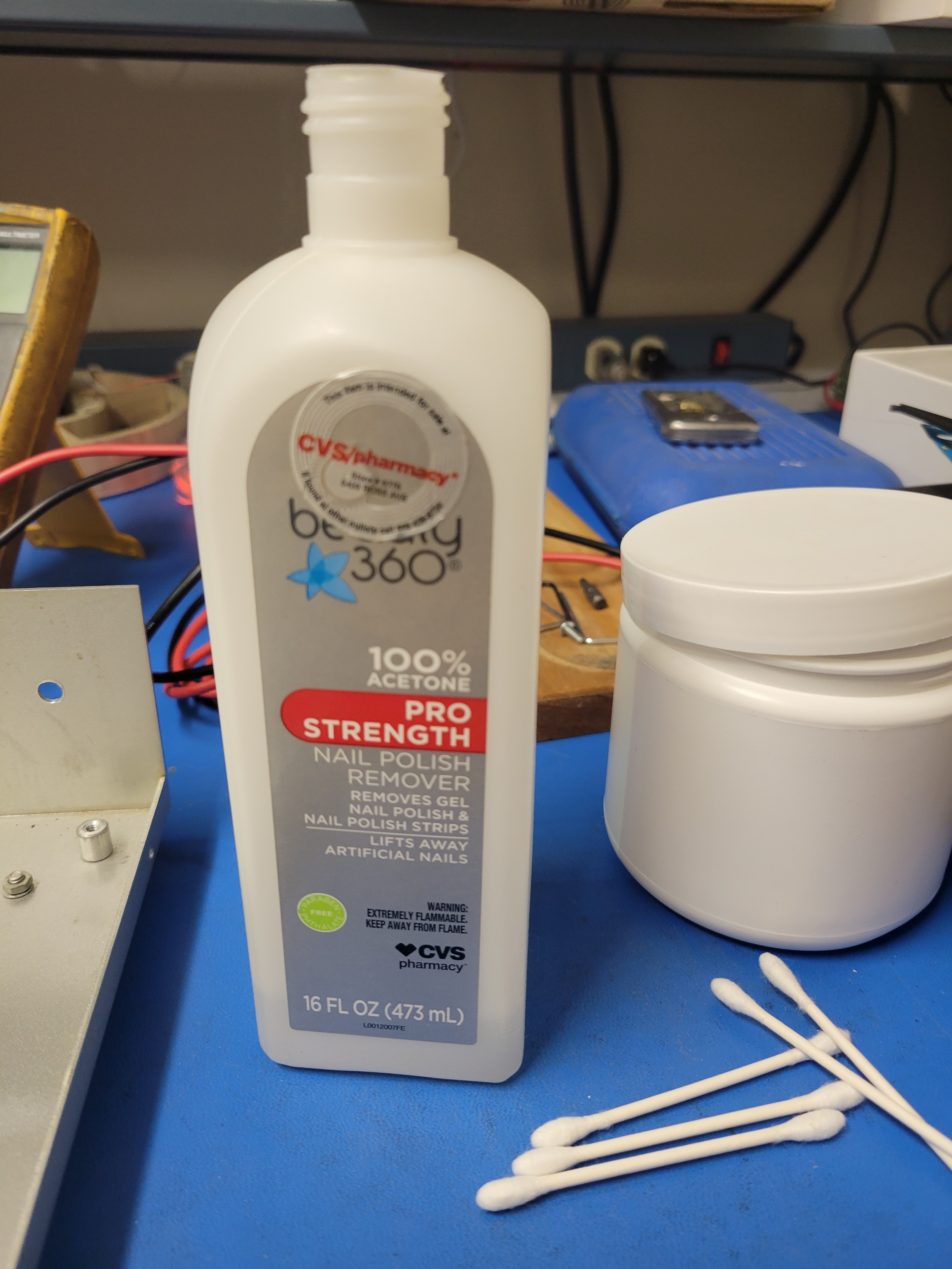
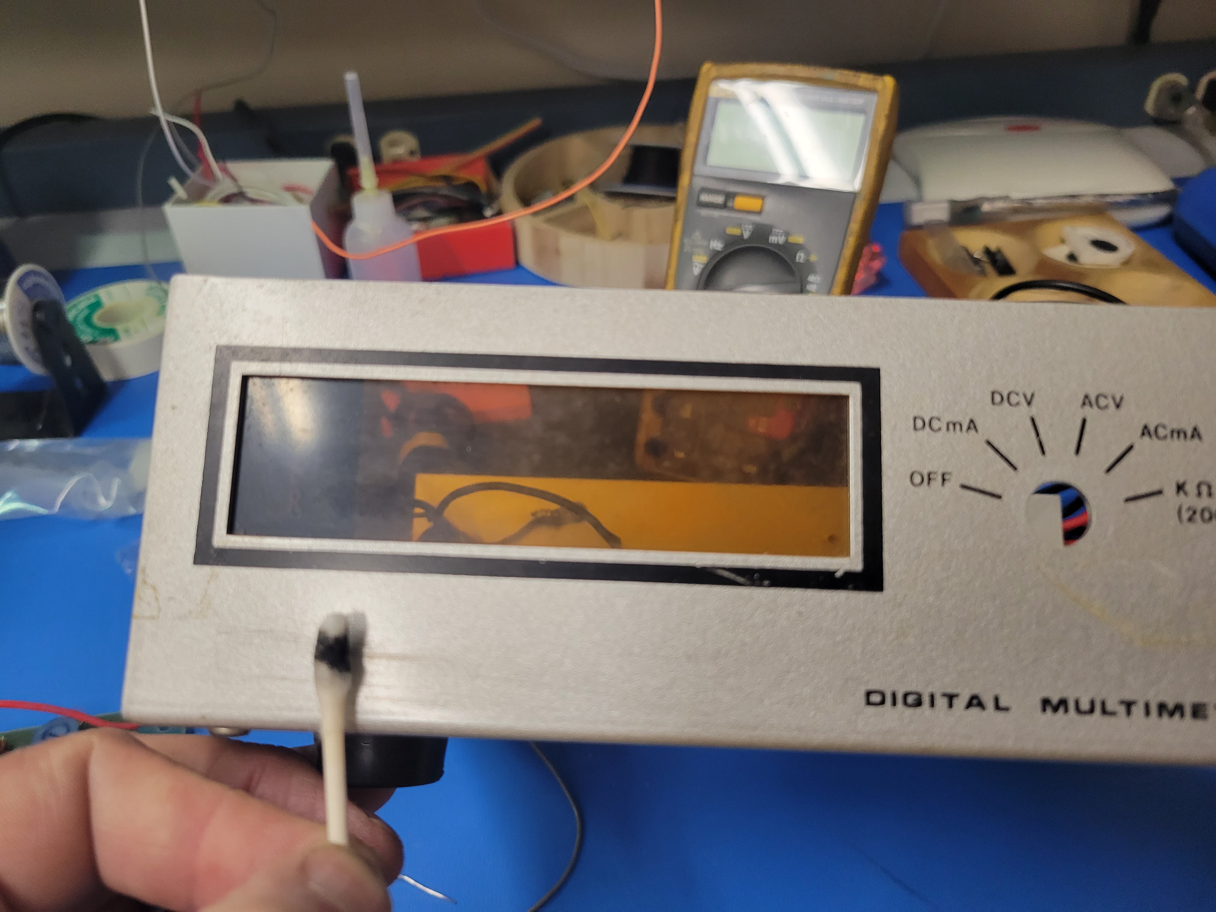
Next, you will remove some of the old graphics on the front faceplate. 100% acetone works great for this. It will remove the black silk screened graphic without damaging the silver painted base. Use q-tips to apply the acetone so you don't get it on your fingers. It will take several q-tips. But, it will all clean off with very little effort. I leave the black printed border around the display window.
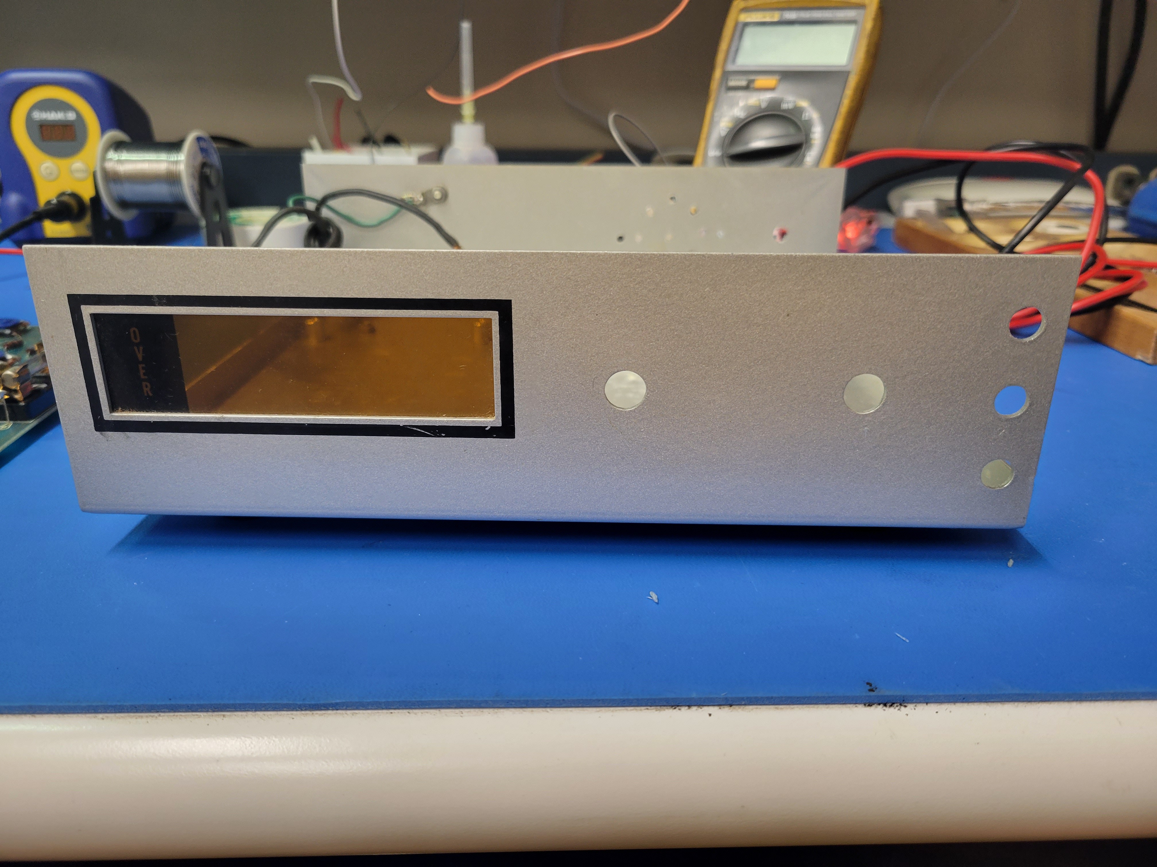
![]()
![]()
Tip: Pour a little of the acetone from the bottle into the cap to dispense the fluid onto the q-tips.
![]()
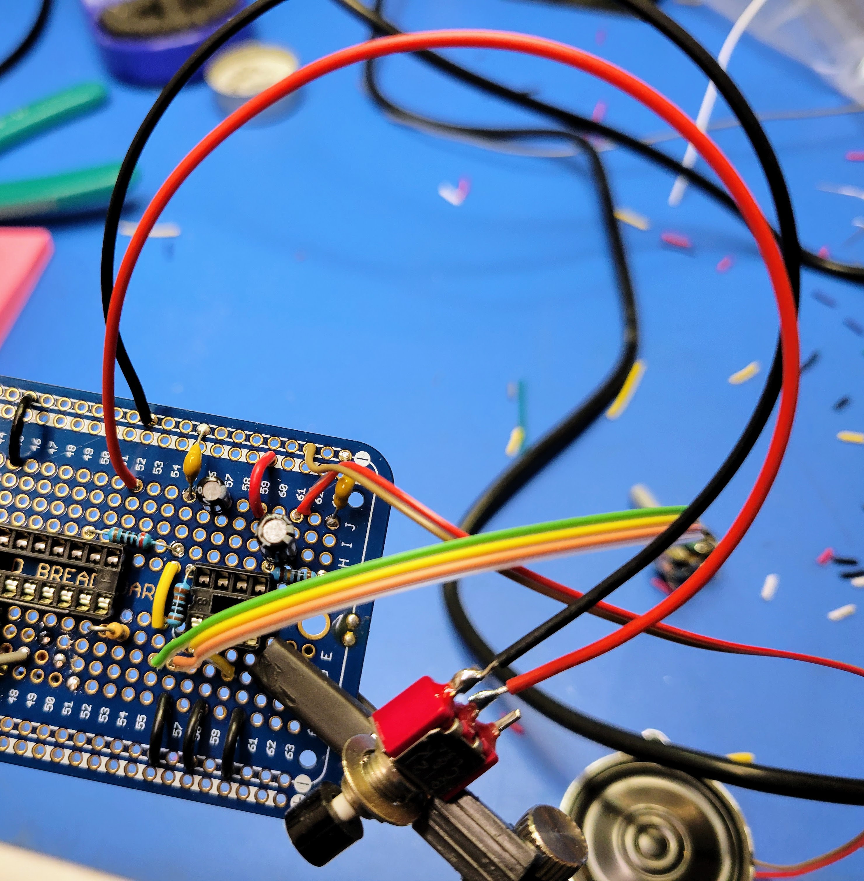
Before re-assembling the PCB and the base of the case, solder the red power wires to the toggle on/off switch.
![]()
Now reinstall the PCB into the base of the case using the five screws you removed before and install the toggle switch to the rear of the case.
![]()
Lastly, re-solder the power cord wires back to the lead on the transformer and the fuse.
![]()
It should look like this when you are done.
![]()
You are now ready to start building the controller board.
-
Acquiring the Parts
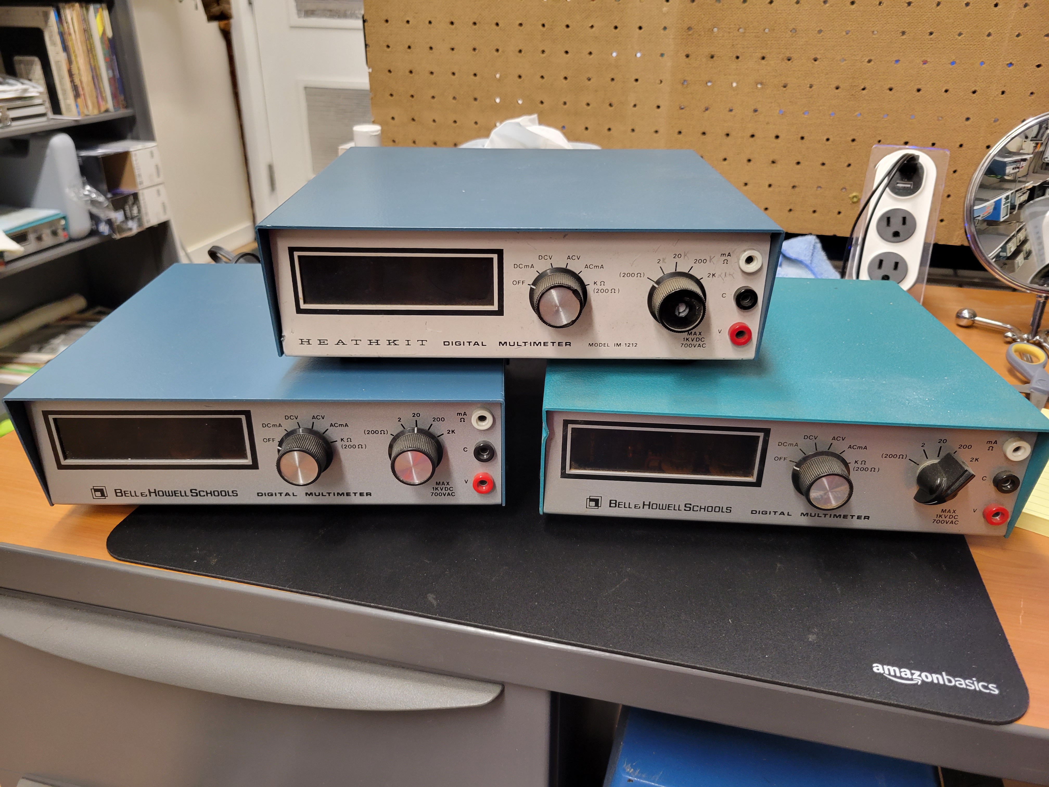
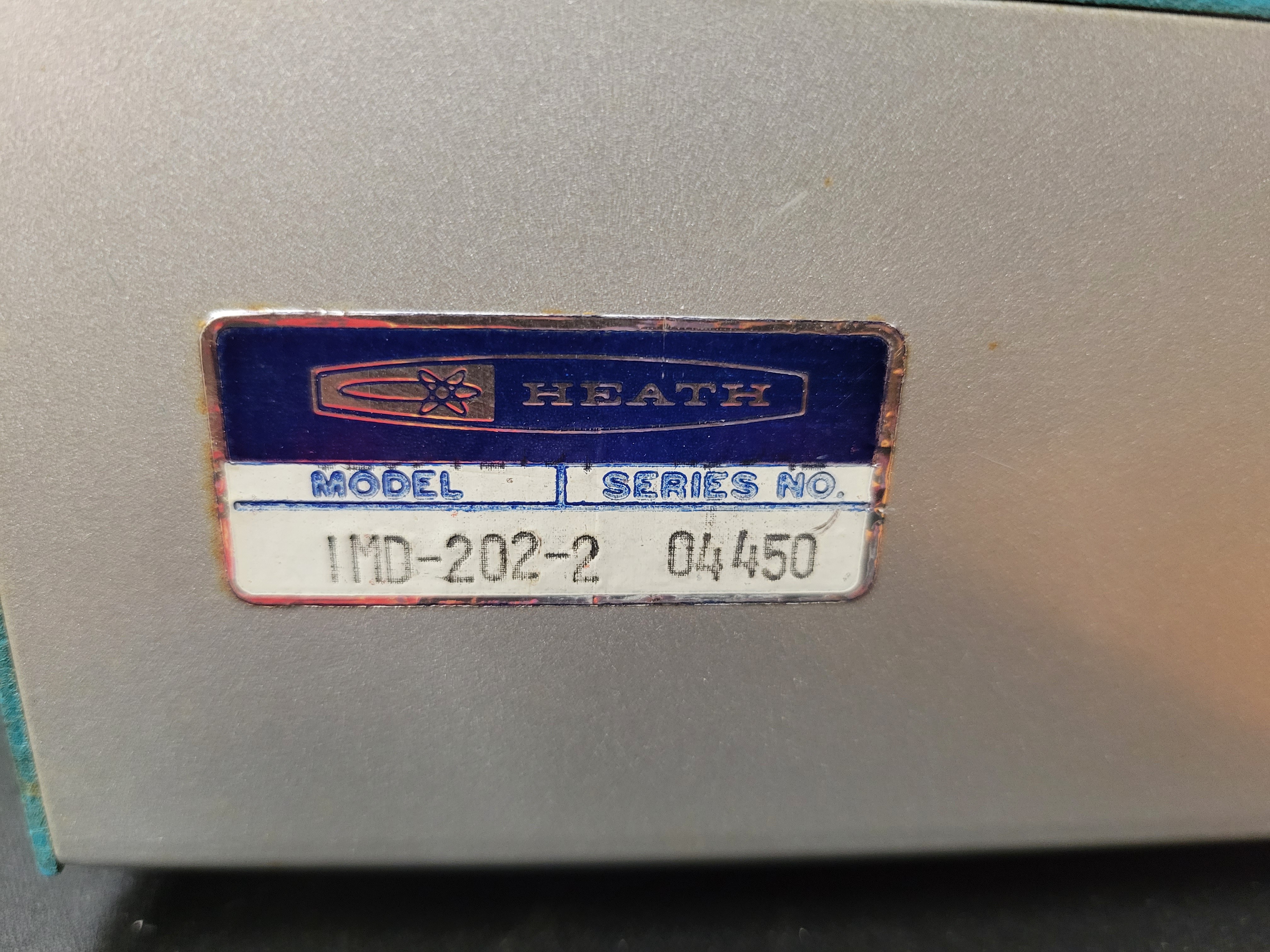
08/01/2022 at 04:51 • 0 commentsTo build the Bell & Howell digital multimeter based digital dice tower, you first need to get a Bell & Howell IMD 202-2 Digital Multimeter. These were originally kits that were assembled as part of the Bell & Howell electronics curriculum back in the late 70's. Apparently, the course and/or the kits were reasonably popular at the time. Because, it's not hard to find them in decent condition today.
![]()
![]()
Note: In the picture above, I've included a Heathkit model IM-1212 digital multimeter as well. That is the original design the Bell & Howell IMD-202-2 is based on. So it can be a substitute for the Bell & Howell meter. However, the Heathkit IM-1212 are a little harder to find and tend to cost much more.
As you can see in the picture, they came with one of two different paint schemes for the top of the case. The internals are all the same no mater which case top it has.
I bought all of my meters from Ebay. If you have a little patience, you can buy one in pretty good condition for $50 plus shipping. That's a pretty good deal for a case, nixie tubes, 7441 decoder/drivers, power supply, and power cord.
Tip: Don't buy one of these meters unless the seller has a picture of it powered up and the Nixies are displaying readable digits. The only bad component I have discovered in the 15 different meters I have bought, is one or two bad 7441 decoders/drivers. These are not easy to find or cheap to replace. If they are bad, you won't be able to display digits on the nixies. So, make sure the seller posts a pic of it powered on with the digits displaying.
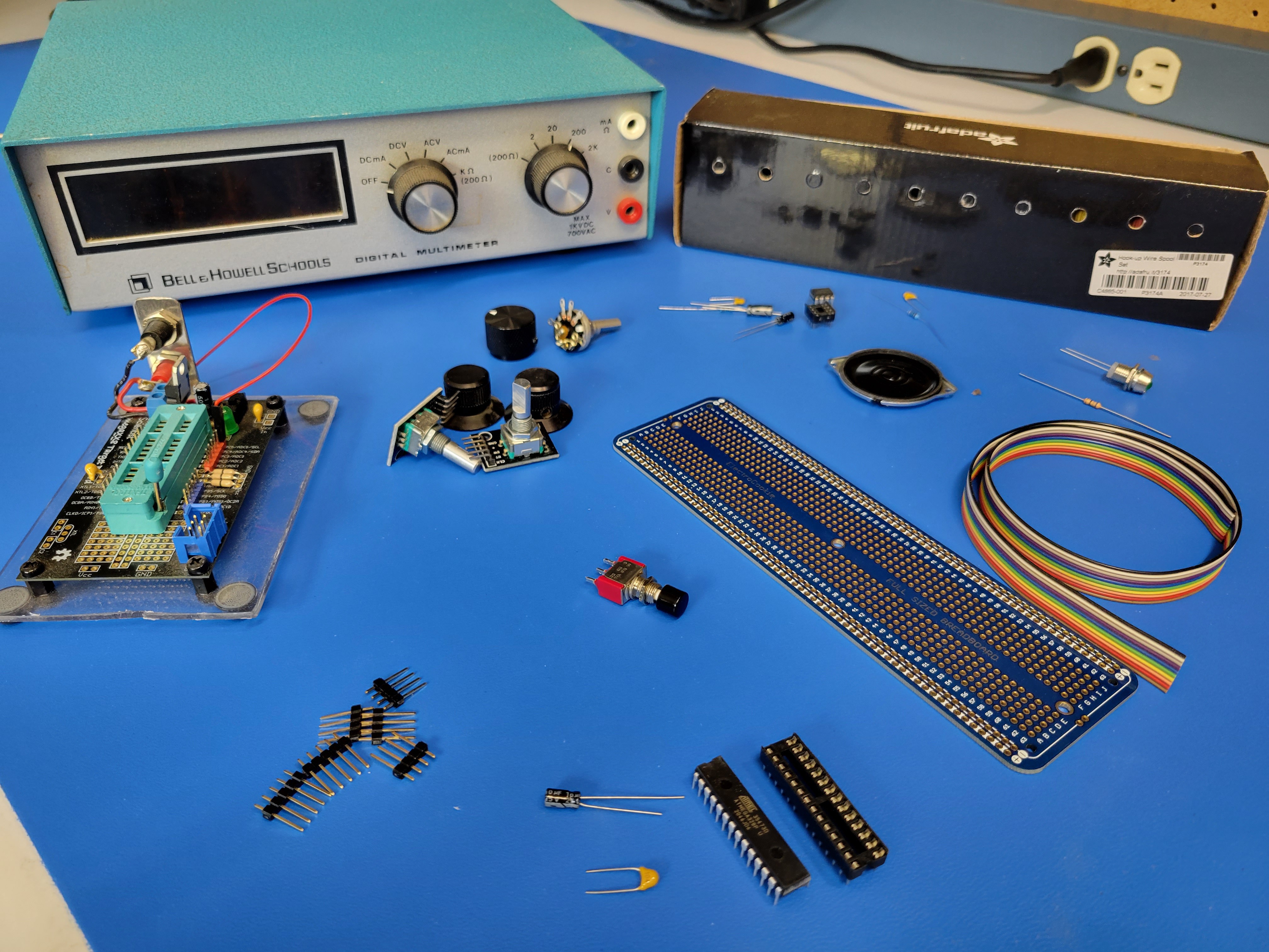
The remainder of the parts can be purchased new from various sources like Amazon or Digi-key. Although buyer beware when ordering parts from Amazon.
![]()
Here's the Bill of Materials (BOM) for all the components.
Audio
- LM386-1 op amp in 8 pin dip package
- 8 pin dip socket
- 10 potentiometer
- 10 Ohm resistor
- 0.1 uF ceramic cap (104)
- 10 uF electrolytic cap
- 220 uF electrolytic cap
- small 8 Ohm speaker
Audio low pass filter
- 0.1 uF ceramic cap (104)
- 200 Ohm resistor
Decoupling capacitors
- 10 uF electrolytic cap
- 0.1 uF ceramic cap
Microcontroller
- ATmega 328P in 28 pin dip package
- 28 pin dip socket
Controls/Indicators
- 6mm Panel mount momentary push button switch
- 2 pcs KY-040 Rotary Encoder Module
- 5mm LED (Green)
- 68 Ohm resistor
- Panel mount 5mm LED holder
- Small panel mount 10K potentiometer
Misc
- On/Off toggle switch at least 120V/2A
- 10 conductor ribbon cable
- Single row 2.54mm header (40 pins)
- Spool or two of 22 awg solid core wire (I like Adafruit's Hook-up Wire Spool Set)
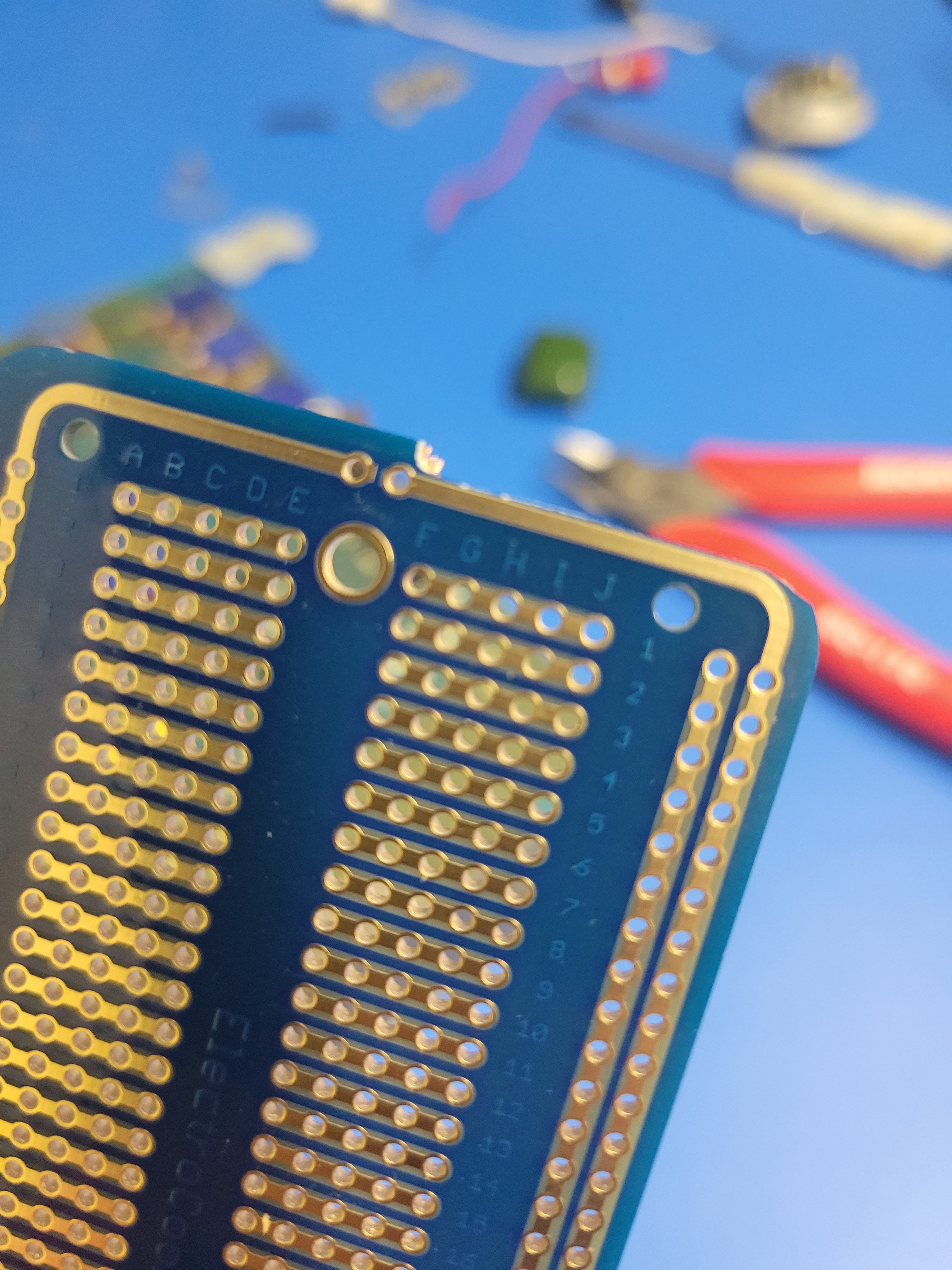
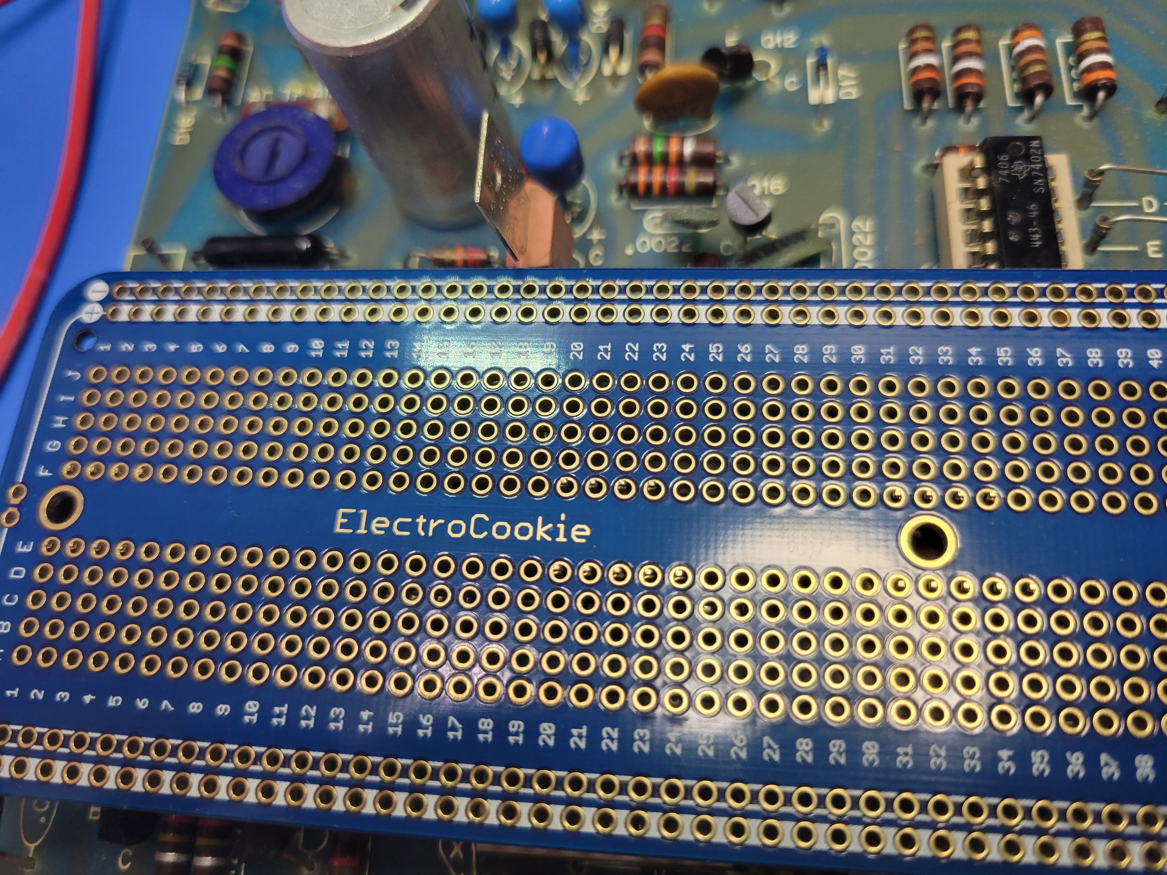
- 63 Row solderable breadboard (I use ElectroCookie's Large Solderable Breadboard)
- Evil Mad Scientist ATmegaXX8 Mini Dev Kit (https://shop.evilmadscientist.com/tinykitlist/230)
-
Building the revised Bell & Howell Digital Multimeter based Dice Tower
08/01/2022 at 03:51 • 0 commentsIn a previous log, I mentioned that I have revised the original design of the Bell & Howell digital multimeter based Digital Dice Tower. I presented some of the features in that log and provided a video of how it works. Now, I am starting a new series of logs that step you through the build in significant detail. I'll be posting these logs over the next few weeks.
- Acquiring the Parts, bill of materials (BOM)
- Prep the Case and Board, steps to prepare the case and PCB
- Build the Controller (Part 1), Solder the dip sockets, power bus, and audio circuit on the controller board
- Build the Controller (Part 2), Solder the connections to the nixie display drivers and lamp transistors/drivers
- Build the Controller (Part 3), Connect and install the rotary encoders, button, LED, and speaker
- Mechanical Assembly, Apply graphics, install the controller, mount speaker, LED, and controls
- Software and ICs, options to program the ATmega 328P and a walk through the software
- It's Alive!!!, demonstration of the new digital dice tower
Resto-Mod Audible Digital Dice Towers
Art, engineering, retro cool, and modern geek all in one package