-
USB keyboard feature so very nearly done
11/11/2022 at 14:59 • 0 comments# Keyboard
You know when you're 🤏 thiiis close to completing a feature, and then you hit that "one tiny snag"? Yeah, that.
I have all the keys mapped out and can accurately report key press/release events. However, I have 189 keys which is quite a bit more than a "standard USB keyboard", so my plan was to report the "standard" keys using a built-in library (including mapping [REV] and [FWD] to [CTRL] and [ALT], etc.), and have the remainder of the keys send text macros until I write a host-side serial driver to interpret them (for instance, [FILE MNGR] could map to [WIN]+E, but I don't want to be that specific at the firmware level).
Anyone who's tinkered with microcontrollers knows that the Arduino IDE has, uh, lots of potential. That is to say, it works but phooey is it cumbersome as an editor. So I'm doing my coding in IntelliJ (using the CLI version of the compiler and using the Teensy loader to connect to the hardware, and also still running the Arduino IDE solely for its simple serial monitor.
Alas! Going off piste frequently means hitting bumps, and one such is that the standard Arduino headers are not implicitly available. So I can have `#include <Keyboard.h>` and have everything building just fine up until the moment I try to call `Keyboard.press(keycode)`. And yes, I have of course set the device mode in the Arduino IDE as per instructions, but those instructions don't take nonconformity into account. I imagine I can simply `#include "path/to/Keyboard.h"`, but I haven't found that path yet.
# Open source
Not that there was ever any doubt, I just hadn't gotten around to it yet -- this project is naturally going to be open source. Insofar as it makes sense given that the intended hardware for it is both rare and expensive. As of this writing, the code resides at GitHub and is under a 3-clause BSD license.
To be continued...
-
Alive with a Teensy 3.5 microcontroller
10/17/2022 at 22:32 • 0 comments...would be an inaccurate title. But, I felt it about time to post an update.
# New brains!
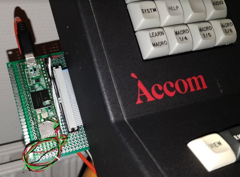
Now that I've received the Teensy 3.5 that Paul Stoffregen was kind enough to sell me, what's actually going on is that I've got the ribbon cable (ie. three of the boards) hooked up to the new microcontroller.
![Teensy 3.5 connected to ribbon cable Teensy 3.5 connected to ribbon cable]()
Teensy 3.5 connected to ribbon cable Obviously, that there is not going to be the final placement. The plan is to have it placed neatly inside and expose a USB device socket on the back. I have already installed a C7 ("figure 8") socket in the back and connected it to a repurposed half-broken USB charger, and to a power supply originally intended for 12V drop ceiling lights. This will provide ample 5V and 12V power for the main board.
Without much planning, I chucked the Teensy onto a breadboard, placed a 34-pin ribbon cable socket next to it, and soldered away! There are no mistakes or shorts ... but there's a reason I'm only showing you the one side here. The rolled-up bundle of wires is with the intent to route the "reset and reload" button to a classic "reset hole" on the back of the enclosure.
# Old woes...
I admit it: I'm rusty! It must have been 1995 or so that I last wrote a line of C code. The Teensy (ditto Arduino and their compatibles in general) runs C++ which ... I may have read a book on ... long ago. Nevertheless, I've got a few threads going to run a heartbeat, cycle the demultiplexers and monitoring the 8 return lines for keypresses ... as well as a fun little light show on the 5 keys that have LEDs in them, because why the hell not.
On the Raspberry, which supports Python, I had nice sets of key-value maps for the demultiplexers and a simple and neat csv file to store the keymap. C doesn't offer key-value maps, and although the Teensy has an onboard SD card reader, there's no built-in file system library. So I've been making all sorts of dumb mistakes in recreating the triple-for-loop from the Raspberry's Python to the Teensy's C. (Tip: it doesn't help to do this sort of work when you're tired. Who'da thunk?)
Right now I'm (procrastinating) working on prototyping the USB device-mode keyboard output, implementing the keymap configuration, and investigating the need/interest of using event interrupts (rather than thread loops) to capture key presses. I've not made a final decision yet whether I'm going to re-use the existing decoding and multiplexing of the rotary encoders and trackball, or to reroute them directly to a bunch of GPIO pins on the Teensy which are still unused. Comments are welcome on this.
-
Prototype with RasPi and other updates
09/14/2022 at 07:06 • 0 commentsThe plan now is to get the console to a workable state as a keyboard, excluding the track ball, jog wheel, and VFD section. Those are all related to the main board, which will be my next target.
## Preparing to test
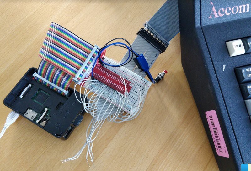
I've mounted all three boards (sans main board) in the enclosure again, intending to connect the ribbon cable to a Raspberry Pi and see if I can get keystrokes to register. (No, I won't be using a Raspberry for the final product, but for prototyping it's okay.) For that purpose, here's (one way) how the control panel's 34-pin ribbon cable can be connected to the Raspberry's 40-pin header:
![ribbon cable converter ribbon cable converter]()
ribbon cable converter The thing is ... at the time of writing, I don't even have a proper breadboard for this. I only have a tiny 25x14 breadboard that absolutely doesn't have enough room for an additional 34-pin ribbon socket when the majority of it is occupied by an "Iduino GPIO Expansion Board". But, I did have an old FDD cable (34 pins!) lying about that I tore up and made work more or less "dead bug style".
## All wired up
![pcb abomination pcb abomination]()
pcb abomination Ain't she pretty? (Please say no.) The good news is, I've got the Axial's ribbon cable connected to my Raspberry Pi.
## Good and bad news from the outside world
The good news is, I've been contacted by a possible sponsor willing to provide me with any pcb fabrication I might need! Clearly, I do have a need ... but it may not be very urgent, because of:
The bad news: I would really, really like to run this project on a Teensy 3.5 (large GPIO count, 5V tolerant, good libraries incl. USB HID mode) ... but what with the global chip shortage, I can expect to have one in my hand by 2023Q2 ... maybe.
In the meantime, I've ordered an Arduino Mega 2560 which at least has plenty of (5V tolerant) GPIO ports, but we'll see how much of a fight it will put up when asking it to be a USB HID device.
The bestest news: Before ordering the Mega, I posted a query to the Hackaday Stack, asking if anyone had a spare Teensy 3.5 they would be willing to part with. Turns out, not only did I get a reply in time to cancel my Mega order, the reply was from Paul Stoffregen himself. Thanks, Paul, you truly are an amazing human being!
The slightly bad news: Shipping the Teensy will take "1-3 weeks" (once it's handled and actually sent), and then probably another week or so when the local customs people want their slice of it.
## Key mapping
I've thrown together a small program to repeatedly cycle through all combinations for the G2A, A, B, and C lines, while looking for signals on any of the return lines. With a bit of user input, this allowed me to map each signal combination to a specific key, which I've stored in a CSV file for now. That was easy enough (once I had debugged two crossed ribbon lines and another that had come loose). As it turns out, three or four keys are either dirty or close to being kaput, judging by their responsiveness.
Next up would be translating this to "user input" for the Raspberry Pi itself, and after that I'll see about passing that input on to a USB host (but that's going to have to wait until I have a USB-device-mode-capable microcontroller).
So for now ... I'm waiting on delivery of the Teensy, and in the meanwhile digging more into the main board logic.
-
Keyboard board
09/12/2022 at 08:42 • 0 comments# 2022-09-14 Keyboard
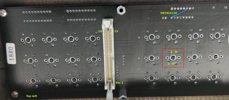
This board holds 99 keys total, spread out across a qwerty layout (64 keys), a "function key" row (14 keys), and a combined numeric/navigation block (21 keys).
![Keyboard board, front Keyboard board, front]()
Keyboard board, front ![Keyboard board, back Keyboard board, back]()
Keyboard board, back Sidebar: Oh yeah, this one's a bit out of chronological order.
I don't know why I started on the main board before being done with all three input boards. Eh, just blame my adhd. Anywho, here's filling in the gap. After this, I should be able to hook the ribbon cable up to a Raspberry and address most of the keys; I'll then continue with the VFD section, the trackball and the jog wheel.
On the other boards, the switch casings themselves are merely soldered to the boards; they are not mounted onto a panel. Here, though, the key switches are mounted onto a separate 2mm steel plate which is screwed in place covering the large enclosure cut-out, making this board by itself weigh more than 1.25kg. This is obviously great for stability, but also prevents access to the front-side traces unless I either desolder all the switches from the board, or unclip all the switch casings from the plate, neither of which I'm going to do.
Arbitrarily numbering things:
- keyboard
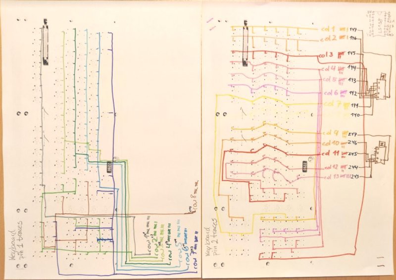
- ugh, mapping these turned out to be a bit of a mess. Rather than describing them here, I'm providing separate files with some colourful schematics as well as a spreadsheet of the complete key matrix.
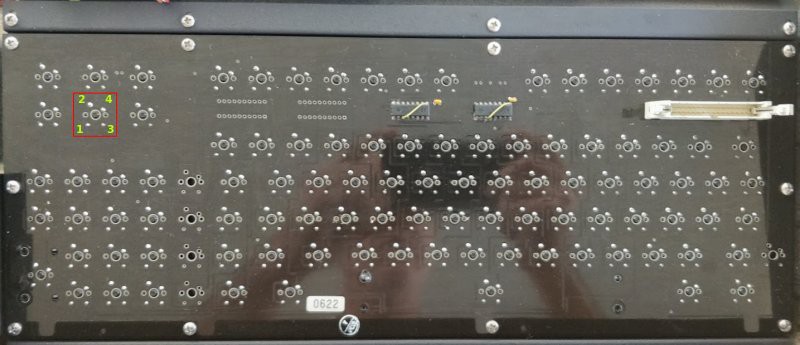
- key switches (red frame in above image):
- pin 1 is connected across the whole column-ish
- pin 2 is connected across the whole row-ish
- pin 3+4 are shorted to pin 2 when the switch is pressed
- between pins 1 and 2, there is a diode within the switch casing
- demultiplexers
- demultiplexer 1 and 2, with the one closest to the ribbon cable being chip 1
- ribbon cable
- standard numbering; pin 1 is closest to [3] and pin 34 is closest to [VIEW]
This board also uses the same demultiplexer select lines (23, 25, and 27) as the other boards.
On this board, pins 1 and 2 are switched around compared to the others: here, pin 2 on the key switches are run directly to the ribbon cable, and pin 1 on the key switches are run through a demultiplexer. However, the large number of keys on this board exceeds the capacity of a single chip, so there are two of them. About 2/3rds of the keys are run through demultiplexer 1, with the remainder being run through demultiplexer 2.
As usual, G1 is pulled high and G2B is pulled low, but each demultiplexer has its G2A pin is routed to separate ribbon lines: demultiplexer 1 uses ribbon line 21, and should be pulled low when scanning; demultiplexer 2 uses ribbon line 23, and should be pulled low when scanning. Note that ribbon line 23 is shared with the jog board (effectively placing a third of the keyboard keys on the jog board).
Curiously, the demultiplexer chips have no manufacturer or type printed on them, but are simply stamped with "Malaysia" and what is probably a serial number ("02M4" and "02G9"). I'm assuming they are compatible with the `SN74LS138` found on the other boards. Also, they're mounted upside-down on the underside of the board; the square solder pad is actually pin 8.
I've mapped the matrix in this shockingly artful diagram:
![keyboard matrix diagram keyboard matrix diagram]()
keyboard matrix diagram So in short, here is my new knowledge about the ribbon cable:
Ribbon line
Source
Signal
19
Main board
Keyboard board G2A chip 2
21 Main board Keyboard board G2A chip 1 Omitted: all of the bloody keys?! Well yeah, but they're listed in the spreadsheet file with the complete keyboard matrix.
- keyboard
-
Jog wheel board
09/12/2022 at 08:28 • 0 comments# Jog wheel board
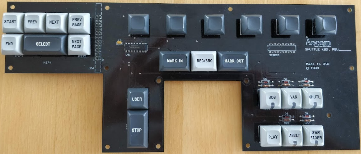
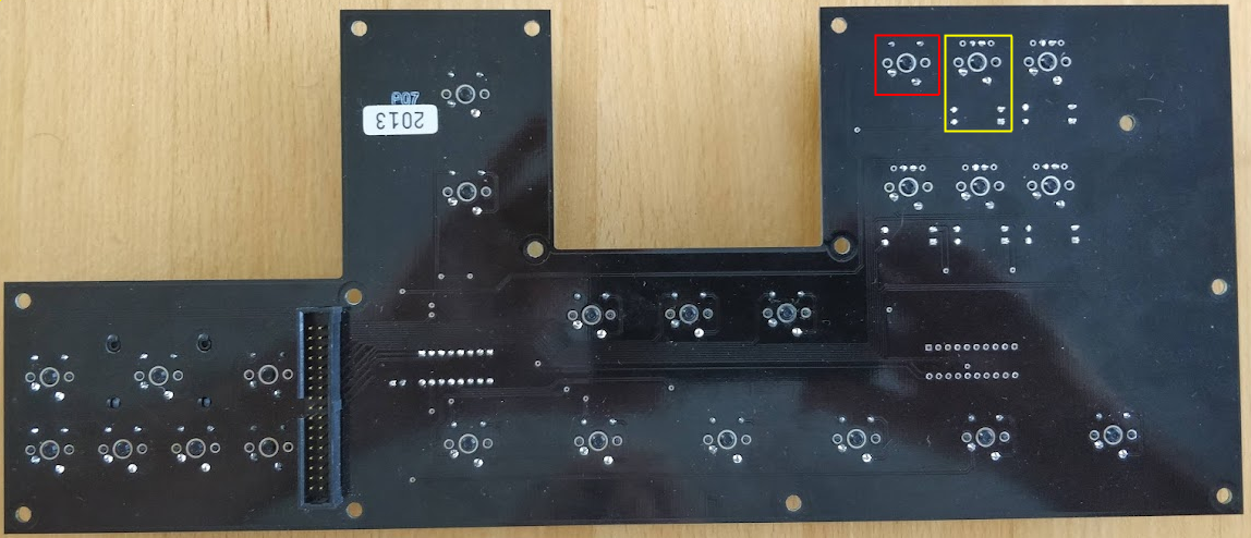
This board holds 24 keys and 5 LEDs.
![Jog board, front Jog board, front]()
Jog board, front ![Jog board, back Jog board, back]()
Jog board, back ![Key switch pin-out Key switch pin-out]()
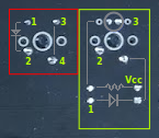
Key switch pin-out The keys on this board are far from as orderly laid out as on the function board, so mapping them is also rather more messy.
Arbitrarily numbering things:
- key switches (red frame in above image):
- pin 1 is connected across various keys
- pin 2 is connected across various keys
- pin 3+4 are shorted to pin 2 when the switch is pressed
- between pins 1 and 2, there is a diode within the switch casing
- lighted key switches (yellow frame in above image):
- pin 1 is connected across various keys
- pin 2 is connected across various keys
- pin 3 is negative terminal for LED
- in this case, the pin 1 diode is external to the switch casing
Surprise: this board uses the same demultiplexer select lines (23, 25, and 27) as the function board. Perhaps other G1/G2 settings, then? Yes: G1 is pulled high and G2B is pulled low as above, but G2A is routed to its own ribbon line (19), and should be pulled low when scanning.
As before, pin 1 on the key switches are run directly to the ribbon cable, and pin 2 on the key switches are run through a demultiplexer. Also as before, the demultiplier outputs and the return lines are active LOW, so all except the signalled line(s) will be set HIGH.
Demultiplexer
Pin
In
Out
1
Select A
2
Select B
3
Select C
4
G2A
5
G2B hardwired to GND
6
G1 hardwired to 5V
7
unused
8
GND
9
unused
10
unused
11
unused
12
unused
13
[REC/SRC], [MARK OUT], [JOG], [VAR], [SHUTL], [PLAY], [ABSLT], [SWR FADER]
14
[END], [SELECT], [NEXT PG], [STOP], [MARK IN] [VFD 1], [VFD 3], [VFD 5]
15
[START], [PREV], [NEXT], [PREV PG], [USER], [VFD 2], [VFD 4], [VFD 6]
16
5V
So it would seem that, to scan this board, I need to run a binary sequence 0-2 through ribbon lines 23, 25, and 27 to power the jog board keys (pin 2) as follows:
int
bin
r27
r25
r23
IC pin
output (to key switches pin 2)
0
000
L
L
L
Y0, pin 15
[START], [PREV], [NEXT], [PREV PG], [USER], [VFD 2], [VFD 4], [VFD 6]
1
001
L
L
H
Y1, pin 14
[END], [SELECT], [NEXT PG], [STOP], [MARK IN] [VFD 1], [VFD 3], [VFD 5]
2
010
L
H
L
Y2, pin 13
[REC/SRC], [MARK OUT], [JOG], [VAR], [SHUTL], [PLAY], [ABSLT], [SWR FADER]
3
011
L
H
H
Y3, pin 12
unused
4
100
H
L
L
Y4, pin 11
unused
5
101
H
L
H
Y5, pin 10
unused
6
110
H
H
L
Y6, pin 9
unused
7
111
H
H
H
Y7, pin 7
unused
Any pressed key switches (pin 1) should then be signalled on (odd-numbered) ribbon lines 1-15:
key switches pin 2 output
ribbon line
[PREV], [MARK IN], [REC/SRC]
1
[START], [END], [MARK OUT]
3
[SELECT], [NEXT], [PLAY]
5
[PREV PG], [NEXT PG], [JOG]
7
[VFD 1], [VFD 2], [VAR]
9
[VFD 3], [VFD 4], [SHUTL]
11
[VFD 5], [VFD 6], [ABSLT]
13
[USER], [STOP], [SWR FADER]
15
Additionally, 5 of the keys have LEDs; these are all supplied with the same 5V from ribbon line 6/8/10 and individually lighted by pulling pin 3 down via separate ribbon lines.
So in short, here is my new knowledge about the ribbon cable:
Ribbon line
Source
Signal
1
Jog board
[PREV], [MARK IN], [REC/SRC]
2
Main board
GND for [VAR] LED
3
Jog board
[START], [END], [MARK OUT]
4
Main board
GND for [JOG] LED
5
Jog board
[SELECT], [NEXT], [PLAY]
7
Jog board
[PREV PG], [NEXT PG], [JOG]
9
Jog board
[VFD 1], [VFD 2], [VAR]
11
Jog board
[VFD 3], [VFD 4], [SHUTL]
13
Jog board
[VFD 5], [VFD 6], [ABSLT]
15
Jog board
[USER], [STOP], [SWR FADER]
19
Main board
Jog board G2A
29
Main board
GND for [SWR FADER] LED
31
Main board
GND for [ABSLT] LED
33
Main board
GND for [SHUTL] LED
- key switches (red frame in above image):
-
Tracing the function board
09/12/2022 at 08:23 • 0 comments# 2022-09-06 Tracing the function board
This board holds 48 keys.
![Function board, front Function board, front]()
Function board, front ![Function board, back detail Function board, back detail]()
Function board, back detail Arbitrarily numbering things:
- function clusters
- cluster A-D as seen from left to right from the front
- Note: cluster E is located on the main board (see later)
- columns 1-4 as seen from left to right from the front
- rows 1-3 as seen from top to bottom from the front
- cluster A-D as seen from left to right from the front
- key switches (red frame in above image):
- pin 1 is connected across the whole column
- pin 2 is connected across the whole row
- pin 3+4 are shorted to pin 2 when the switch is pressed
- between pins 1 and 2, there is a diode within the switch casing. This eliminates ghosting when multiple keys are pressed simultaneously.
- ribbon cable
- standard numbering; pin 1 is closest to [LIST IO] and pin 34 is closest to [MACRO 3/6]
Examining the board traces, I am relieved to find that the keys are laid out in a matrix, and that the four clusters are logically aligned in an interlaced square so that columns 1-4 are shared between clusters A+C and B+D, and rows 1-3 are shared between clusters A+B and C+D.
The 8 column lines (pin 1 on the key switches) are run directly to the ribbon cable, but the 6 row lines (pin 2 on the key switches) are run through a TI SN74LS138 demultiplexer (which, by the way, is rated to switch within 40ms, so scanning should be at no more than 25Hz). The demultiplexer reduces the line count to 4, which are run to the ribbon cable. The demultiplier outputs, and hence the return lines, are active LOW, so all except the signalled line(s) will be set HIGH.
Demultiplexer
Pin
In
Out
1
Select A
2
Select B
3
Select C
4
G2A
5
G2B hardwired to GND
6
G1 hardwired to 5V
7
C+D row 3
8
GND
9
A+B row 3
10
C+D row 2
11
A+B row 2
12
C+D row 1
13
A+B row 1
14
unused
15
unused
16
5V
So it would seem that, to scan this board, I need to configure the G lines thusly:
G1
G2A
G2B
H
L
L
and then run a binary sequence 2-7 through ribbon lines 23, 25, and 27 to power each cluster row's key switches (pin 2) as follows:
int
bin
r27
r25
r23
IC pin
output (to key switches pin 2)
0
000
L
L
L
Y0, pin 15
unused
1
001
L
L
H
Y1, pin 14
unused
2
010
L
H
L
Y2, pin 13
A+B row 1
3
011
L
H
H
Y3, pin 12
C+D row 1
4
100
H
L
L
Y4, pin 11
A+B row 2
5
101
H
L
H
Y5, pin 10
C+D row 2
6
110
H
H
L
Y6, pin 9
A+B row 3
7
111
H
H
H
Y7, pin 7
C+D row 3
Any pressed key switches (pin 1) should then be signalled on (odd-numbered) ribbon lines 1-15:
keypress
ribbon line
A+C col 1
1
A+C col 2
3
A+C col 3
5
A+C col 4
7
B+D col 1
9
B+D col 2
11
B+D col 3
13
B+D col 4
15
So for instance, to test whether the [SYSTM] key (cluster A, row 2, col 1) is being pressed, I should set lines 23 and 25 LOW and line 27 HIGH (for cluster A row 2), and check for a LOW on ribbon line 1 (for cluster A col 1). Similarly, pressing [LIST] (cluster B, row 3, col 1) should give a LOW signal on ribbon line 9 when line 23 is set low and lines 25 and 27 are set high; and pressing [EJECT] (cluster C, row 1, col 4) should give a LOW signal on ribbon line 7 when lines 23 and 25 are set high and 27 is set low.
Meanwhile, G2A (on ribbon line 17) should be pulled low.
Having seen this, I expect the other boards to use the same signal return lines, but separate demultiplexer select lines.
According to the demultiplexer's data sheet, the voltage on ribbon pin 6/8/10 should be between +4.5V and 5.5V; the voltage on ribbon pins 23/25/27 should be between 2V and 5V; and the output voltage would be between 2.5V and 3.5V. These values indicate that it's safe to test with the RasPi2B+ that I already have.
Update: Yup, that works as per datasheets. Good to know.
This is what I now know about the ribbon cable:
Ribbon line
Source
Signal
1
Function board
A+C col 1
3
Function board
A+C col 2
5
Function board
A+C col 3
6
Main board
5V
7
Function board
A+C col 4
8
Main board
5V
9
Function board
B+D col 1
10
Main board
5V
11
Function board
B+D col 2
13
Function board
B+D col 3
15
Function board
B+D col 4
17
Main board
Function board G2A
23
Main board
Demultiplexer Select A
25
Main board
Demultiplexer Select B
26
Main board
GND
27
Main board
Demultiplexer Select C
28
Main board
GND
30
Main board
GND
32
Main board
GND
34
Main board
GND
- function clusters
-
CPU and keyboard considerations
09/12/2022 at 08:19 • 0 comments# 2022-09-05 CPU and keyboard considerations
## CPU
I've thunk about possible solutions, and keeping the hardware original seems less and less likely. For one thing, there's really no reason to, and not doing it gives me much greater freedom to interface the hardware with a new controller.
### Out with the Zilog
I'm not going to investigate re-using the Zilog Z80 CPU; it's just not something I'm interested in spending time or gaining experience with. Also, it's likely getting its orders from firmware EPROM chips that I have neither the equipment nor the inclination to work with.
True, I'll have to isolate the Z80 and EPROM chips from the rest of the main board and wire in a replacement. Probably not too big of a deal; first I want to figure out how much of the rest of the components I can benefit from using as-is.
### In with a microcontroller board
I expect I'll be using some form of microcontroller board for a number of reasons:
- First, note that I'm saying "microcontroller board", that is, one of the (Arduino, Feather, Pyboard, Raspberry Pico, Teensy) family. That is to say, I prefer an off-the-shelf all-in-one board over creating my own microcontroller pcb with (only) whatever additional components are needed. That, obviously, would be interesting for a large production run, but not for a one-off toy.
- This also means I get to program in a higher-level language (something C-like or even Python) rather than raw microcode. Yes please.
- I'm leaning towards a Teensy, because it supports USB HID device mode which allows this thing to pretend to be a "regular keyboard" to any pc it's connected to. (It also has a USB host port, but that's not immediately interesting.)
- I am not yet sure how many GPIO lines I'll need; this impacts which microcontroller board I could choose.
## Keyboard
A crucial point is how the boards are currently wired up, or specifically, how keypresses are detected: are the boards designed to use matrix scanning? Examining the boards should reveal that.
- The matrix design needs quite a lot of lines, but basically supports any number of keys in a reasonably straightforward manner. Keep in mind, the ribbon cable currently connecting all the boards has 34 conductors. Given that there are 189 keys, a single key matrix would need 28 pins (14 ✕ 14 lines) which is not unrealistic (but of course, these are spread out across several boards). In addition, there's also the the matter of reading the trackball, jog wheel, and six dials, as well as managing the 23 lightable keys (most of which, by the way, are incandescent and so might draw a non-trivial amount of milliamps). It is possible to drive 30 lamps from only 6 pins by using charlieplexing, but there would be severe limitations on which combination of lamps could be lit at any given moment.
- An alternative to the matrix design is some form of masking or encoding, which would be much more difficult to use as-is. In this scenario, I might resort to cutting traces on the circuit boards and implement matrix scanning, but this might get really messy unless I replace the boards entirely (which I've already explained I want to avoid).
If I/O pins end up becoming a bottleneck, then I might resort to using several microcrontroller boards that talk over a can bus, or maybe I²C.
- First, note that I'm saying "microcontroller board", that is, one of the (Arduino, Feather, Pyboard, Raspberry Pico, Teensy) family. That is to say, I prefer an off-the-shelf all-in-one board over creating my own microcontroller pcb with (only) whatever additional components are needed. That, obviously, would be interesting for a large production run, but not for a one-off toy.
-
Power-on test
09/12/2022 at 08:18 • 0 comments# 2022-08-24 Power-on test
![Internal power connection Internal power connection]()
Internal power connection As mentioned, power was orginally delivered through a 6-pin XLR socket on the rear, internally wired to a Molex connector (which does not follow the Molex standard).
XLR-6pin Molex pin* Cable colour Signal 3 1 Red 5V - for driving the logic, LEDs, and VFD 4 + 1 2 Black GND 2 3 White ?? (not yet traced) 6 4 Yellow 12V ?? - for driving the incandescent bulbs (in the majority of the lighted keys) 5 + shield n/c A power-on test was inconclusive. I had wired up a pc power supply with GND, 5V and 12V to three of the four connectors on the main board's Molex socket (sans yellow), but got no life signs (no beeps, no lights, no text in the VFD). I did not check for signals on the RS422 port.
Possible explanations:
- I wired it up incorrectly.
This may be; I'm only human after all. In any case, I detected no magic smoke leaks. - The power supply couldn't provide sufficient amps. This is a likely explanation, because the power supply was from a somewhat dinky office desktop pc. I have other supplies available to test with. Unfortunately, the installation guide only states total consumption (42W peak) but does not break it down by voltage; I suspect the 12V needs significant amps to run the VFD.
- The control panel is defective. How likely this is is hard to say; the console has a few exterior scratches but no tell-tale marks of hard drops or deteriorated internal components.
Update: I had indeed wired it up incorrectly. I'm going to blame the colouring; R/Y is flipped compared to common pc usage.
- I wired it up incorrectly.
-
First look
09/12/2022 at 08:16 • 1 comment# 2022-08-22 First look
I've taken the thing apart, mostly in order to clean it and identify its components. I had a bit of trouble getting the jog wheel off, as it's fastened to the rotary encoder by two deep-set 1/16th-inch hex screws -- and nearly all my tools are metric. I got it off, but now it's not very tightly affixed. No matter.
![Enclosure stripped bare Enclosure stripped bare]()
Enclosure stripped bare Wowza, that thing is solidly built! The enclosure is bult of 4mm aluminium sheet that seems to have been either laser cut or machined; the way that the blue-tinted plastic sheet covering the display is recessed from the inside makes me think at least that opening was machined, so probably the entire thing. The sides are solid 10mm aluminium that've been machined to mate with, and welded to, the edges of the sheet metal. Also welded to the enclosure are a significant number of stand-offs for the circuit boards as well as the trackball brackets which also has mounting screws flush welded to them. The plate covering the bottom and back is 2mm aluminium sheet with ventilation louvres. To this plate an angled recess has been welded which holds the sockets for power and communication.
While I had the enclosure stripped of its components, it occurred to me that I could take the opportunity to give it a new paint job. But nah, I'm going to keep the original look to retain the Accom and Axial logos, in spite of the scratches (err, I mean, to preserve its patina).
As for the guts, there are four separate boards:
![Guts, annotated Guts, annotated]()
Guts, annotated - (lower left) keyboard, numpad and surrounding keys,
- (lower right) jog/shuttle wheel buttons,
- (upper left) function clusters,
- (upper right) display, knobs and dials (main board, with power, comms, and CPU),
tied together by a 34-line ribbon cable.
The circuit boards are all double-sided, single-layer, and obviously bespoke; curiously, some are dated 1991 and some 1994. Thankfully, the components are regular off-the-shelf items, which makes it easy to obtain datasheets:
- most of the keys use Cherry MX Black switches, though the lighted ones use something else yet to be identified;
- the trackball is a 50mm Disc Instruments LQ200-192-50 which, according to the datasheet, supports up to three button inputs as well;
- the jog/shuttle wheel is backed by an HP HEDS-5701-I02 rotary encoder;
- the character display is a stock NEC FC40X2EA-AB VFD daughter board;
- the dial knobs are backed by Avago HRPG rotary encoders.
![Ports on back Ports on back]()
Ports on back ![Internal power connection Internal power connection]()
Internal power connection Main power was delivered through a 6-pin XLR socket on the rear, internally wired to a Molex connector.
-
Obtaining the hardware
09/12/2022 at 08:08 • 0 comments# 2022-08-06 Obtaining the hardware
I closed the deal on a console that was for sale online. Alas, I believe it does not include the power supply; I shall see when it arrives. I ended up paying around 270 USD including shipping (don't know yet whether there will be customs added to that number).
Update: no power supply, but thankfully also no customs or taxes.
Repurposing an Accom Axial Control Panel
Turning an obsolete video editor console into a mothership-sized keyboard + trackball + stream deck
 noughtnaut