Jon VB
-
Time flies when your having fun
03/04/2023 at 19:48 • 0 commentsBeen pretty busy with redesigning the drones frame to fit the Dev kit board of the ESP32 along with the MPU and Camera. This redesign helped to reduce weight over all for the drone. The weight went from about 70-80 grams down to about 50 grams. Also added some wiring routes for the motors to try and help keep the wiring cleaned up.
The Camera module can now be slid into place easily and removed just the same with no screws. the MPU and MCU are attached to the frame via mounting posts. No, screws should be used here just a bit of hot glue. The MCU also helps to keep the frame ridge to help reduce the frame weight. No, glue on post will make the structure flimsy.
There were some problems trying to get the propellers to print with out errors. I completely redesigned the props to make contact with the print bed along with giving them more surface area at middle and extending a bit more to the tip of the blade.
I started to use a 60C lipo battery and noticed the ESP32 was freezing up when throttle was added to the motors. Took me a bit to figure out the mistake that I had made. with the old battery that was being used the voltage was closer to 3.3V, the newer battery was a good bit higher at 4.2V the pull up resister was placing about 3.8V to the GPIO of the ESP32. After some looking I noticed this and needed to place a TTL logic level N-Channel MOSFET to allow the circuit to function correctly.
Along the way, I also noted that the custom blit_image() function that I was using need to be pulled from the rawdraw project and placed into the projects GUI's *.c and *.h files respectively. This was something that barryjoehawkes had caught. I thank him for that, since I didn't even notice it when I was uploading the project to GitHub.
-
Code... Code everywhere... Code updates
01/03/2023 at 20:53 • 0 commentsOkay, this is going to be a smaller log. Holidays and everything has made life pretty busy so short and sweet for now.
The camera, communication and control has been put together for the ESP32 along with some code clean up. Got ride of some commented out code related to allot of earlier debugging, fixed some logic in the code layout primarily in the TCP end of things. Got rid of allot of over nesting and unnecessary logic bits. After everything has been put together I'm getting about 13 FPS from the ESP. This can probably be improved upon, but that will have to come later. All this has been uploaded to ESP_Drone on GitHub for those interested in having a look.
Along with my code clean up for the ESP32 I did about the same thing for the android side of things. Cleaned up allot of over nesting and unnecessary code. Along with the clean up another thing that I wanted to do was scale up the image since it's only at 320 x 240. This was done using a global added to rawdraws CNFGFunctions.c the globals used are scale_h and scale_w used respectively in CNFGBlitTex().
float scale_h = 0, scale_w = 0;

void CNFGBlitTex( unsigned int tex, int x, int y, int w, int h )
{
    if( w == 0 || h == 0 ) return;

    CNFGFlushRender();

    CNFGglUseProgram( gRDBlitProg );
    CNFGglUniform4f( gRDBlitProgUX,
        1.f/gRDLastResizeW, -1.f/gRDLastResizeH,
        -0.5f+x/(float)gRDLastResizeW, 0.5f-y/(float)gRDLastResizeH );
    CNFGglUniform1i( gRDBlitProgUT, 0 );

    glBindTexture(GL_TEXTURE_2D, tex);

    /*  two triangles

        (0,255)----------(255,255)
          |                  |
          |                  |
          |                  |
        (0,0)------------(255,0)
    */

    volatile uint8_t a = 255, b = 255;

    // Added scaling to the rectangle that the image will be drawn on
    const float verts[] = {
        0,0, (float)w * scale_w,0, (float)w * scale_w,(float)h * scale_h,
        0,0, (float)w * scale_w,(float)h * scale_h, 0,(float)h * scale_h };

    const uint8_t tex_verts[] = {
        0,0,   a,0,  a,b,
        0,0,   a,b,  0,b };

    CNFGglVertexAttribPointer(0, 2, GL_FLOAT, GL_FALSE, 0, verts);
    CNFGglVertexAttribPointer(1, 2, GL_UNSIGNED_BYTE, GL_TRUE, 0, tex_verts);

    glDrawArrays( GL_TRIANGLES, 0, 6);
}
Along with the above code modification, moved around the order of the drawing for the top hat control so it is not drawn over by the displayed image.
Results:
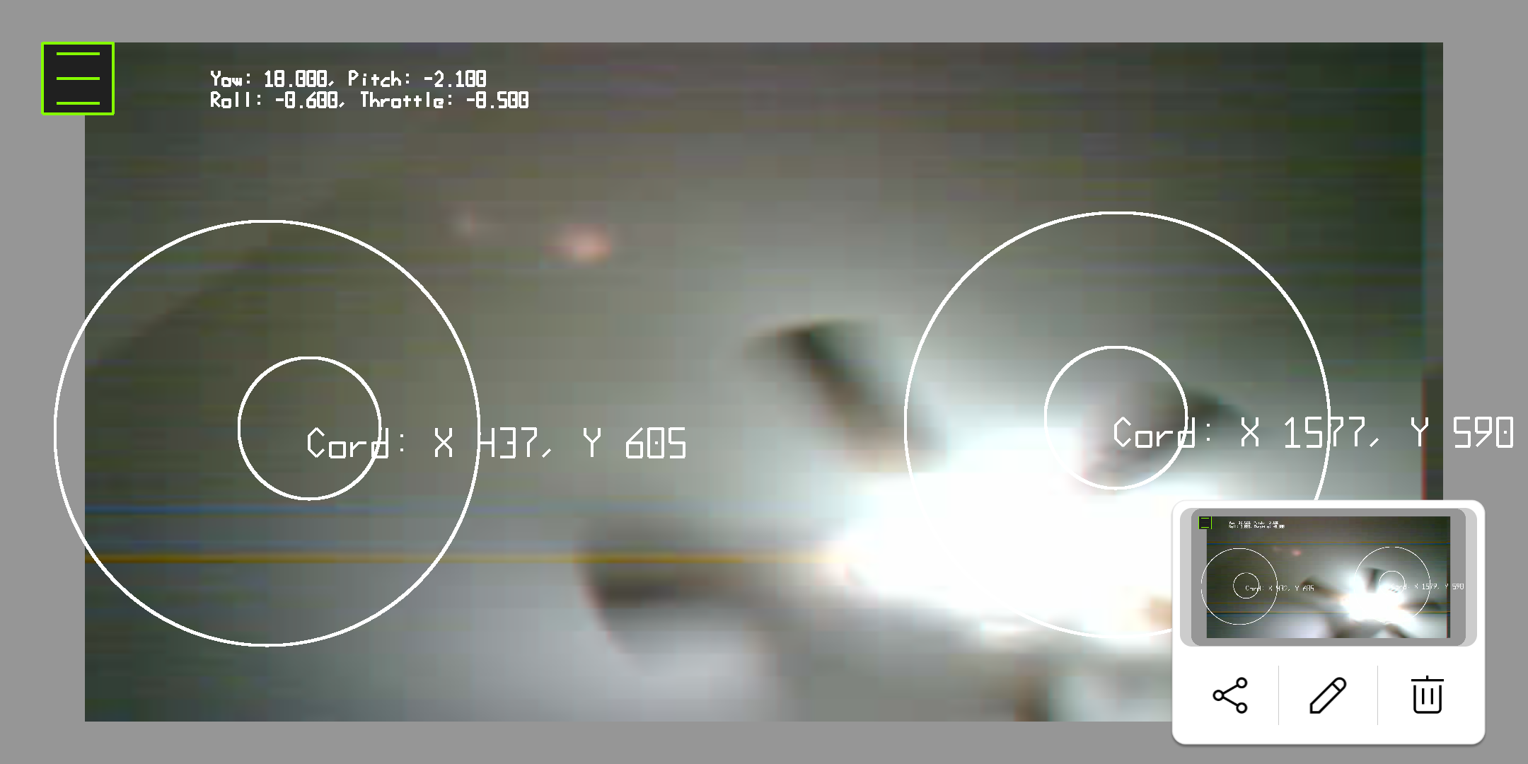
![]()
Sorry for the pic of my ceiling fan lol. It's just how I got the camera wired up right now. There is also a good bit of noise in the images that I will need to clean up, most of this is due to how it's currently wired up for the time being. Got some work to do on the image and getting the controls fully flushed out. For now I'm content with that it's giving me, till after I get some running tests with the full unit. The code for the android side of things can be found here ESPStream. I will have the updated code pushed to GitHub later tonight.
Now I'll be working on getting the drone wired up and ready for some testing. I do plan on building a gimbal rig to check for proper flight instead of yolo'ing it and hoping it works. That would only spell disaster and possibly breaking the unit and parts them selves. I plan on having a gimbal designed and printed up in the next week. I'll post the wiring up process and the first proto unit here in the next few days.
-
Cobbling more together, MPU, PWM and PID
12/20/2022 at 20:05 • 0 commentsSo, after a good bit of time, I was able to put together 3 of the main parts of this project. This should really get this thing going. It took a good bit of searching, recoding and trial/error got it working. So I'm pleased with that.
I did a push to GitHub for this bit of code. This is mainly for motor control and stabilization. The code can be found here. If anyone wants to have a look at it. Suggestions and help are more then welcome.
PWM
Okay, so jumping into what has been done. First, started off with getting the PWM working correctly. This was accomplished using LEDC from ESP-IDF. This can all be found in the component directory of your ESP-IDF installation under C:\Espressif\frameworks\esp-idf-v4.4.2\components\driver\include\driver\ledc.h dependent on your install of course. At first I tried to find an exact replacement that Arduino was using for the build environment then decided to just cut out the middle man and go to the source it's self. There is a good example of how this works, which I went off of here. Props to the author for keeping it simple and to the point. Gave me a good spot to jump off of to start searching/digging from there.
At this point I had to flush out the hardware design for the DC motors. Since the MOSFETs I would be using are P-Channel Enhancement mode MOSFETs both the gate and source had to be tied to Vcc and the drain tied to ground.
![]()
The gate was tied to Vcc via a pull up resistor to keep the MOSFET in the off position. What I did here was just create an electronic switch. Were the logic from the GPIO pin is set to Pulse Width Modulation will toggle this switch to give the desired power to drive the DC motor. For my usage, the logic of the GPIO had to be inverted to compensate for this reverse logic setup of the MOSFET.
If you'd like to learn more about basic electronics check out this site and read up on some of the basics. There are allot of good sites to check out, just pick one that feels good for you and charlie mike. I used a bunch of different sites while I was attending school so no site is a one size fits all, that I know of yet.
PID and MPU
After all that was said and done, got a solid test out of my setup, I went on to the next piece. Tying the MPU, PID and PWM together. I did find a software PID library that was used in the Arduino code I had used already in the Arduino build environment, it just needed a little bit of a modification to get it to work with the ESP-IDF build environment. The Original code can be found here if you want to play around with it a bit, the modified version is included in the component directory of my Git repo for this project.
PID can be a pretty big subject and used for more than the application that this project is using it for. So if you want to dive deeper into this area you can check this out and read up on the subject. As I'm just going to touch on a few things here to show how I'm interacting with the PID controller.
As a basic jest of it. I'm getting the yaw, pitch and roll from the MPU converting that number to an angle then feeding that number into the PID control via an input. But first the PID controller needs to settle for a little bit. the setup I got going it doesn't have any PID tunning, if left for brief period of time the controller will level out giving a better result. the following code achieves this to an extent.
// PID Cal while throttle is at 0
if (target_speed[0] == 0)
{
    ESP_LOGI("PID", "CALIBRATING...");
    ypr_cal[0] = ypr[0] * 180 / M_PI;
    ypr_cal[1] = ypr[1] * 180 / M_PI;
    ypr_cal[2] = ypr[2] * 180 / M_PI;
}
I know this is a sloppy way of doing but it'll work for now. what really matters is the input variable being set here, from the data we got from the MPU.
// getting yaw, pitch and roll from MPU
mpu.dmpGetYawPitchRoll(ypr, &q, &gravity);
printf("YAW: %3.1f, ", ypr[0] * 180 / M_PI);
printf("PITCH: %3.1f, ", ypr[1] * 180 / M_PI);
printf("ROLL: %3.1f\n", ypr[2] * 180 / M_PI);

// setting the input for the PID functions
roll_input = ypr[2] * 180 / M_PI - ypr_cal[2];
pitch_input = ypr[1] * 180 / M_PI - ypr_cal[1];
yaw_input = ypr[1] * 180 / M_PI - ypr_cal[1];
Now with the input set for the PID we can use it's output to adjust the control of the motors with the following.
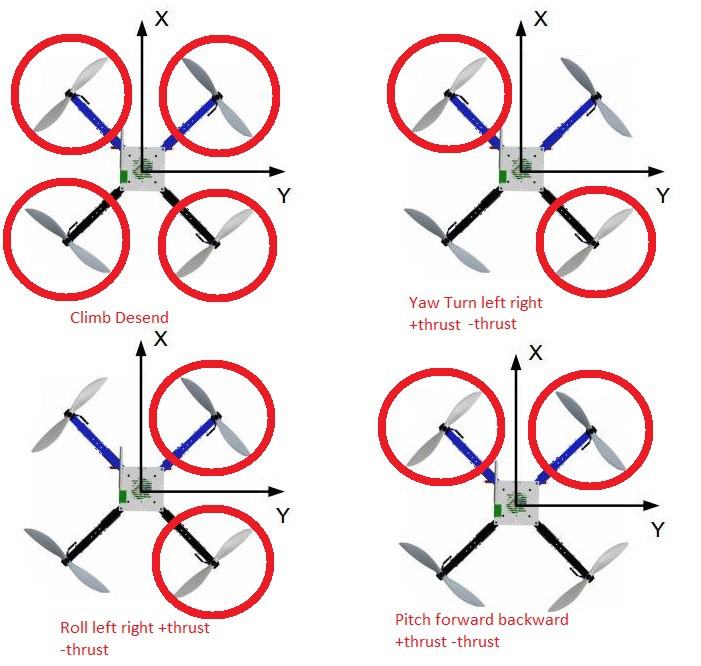
void motor_control_stabilization (int* curr_speed, int* act_speed, double roll_diff, double pitch_diff, double yaw_diff)
{
    /*
     *   As roll_diff goes positive it will roll left as roll_diff goes
         *   negative it rolls right. This goes for all outputs roll, pitch
         *   and yaw.
     */
    act_speed[0] = (int) curr_speed[0] - (roll_diff) + (pitch_diff) - (yaw_diff);     // FL
    act_speed[1] = (int) curr_speed[1] + (roll_diff) + (pitch_diff) + (yaw_diff);    // FR
    act_speed[2] = (int) curr_speed[2] - (roll_diff) - (pitch_diff) + (yaw_diff);    // BL
    act_speed[3] = (int) curr_speed[3] + (roll_diff) - (pitch_diff) - (yaw_diff);    // BR

    for (int i = 0; i < 4; i ++)
    {
        if (act_speed[i] < 0 )
            act_speed[i] = 0;
    }
}
This can be demonstrated better with an illustration.
![]()
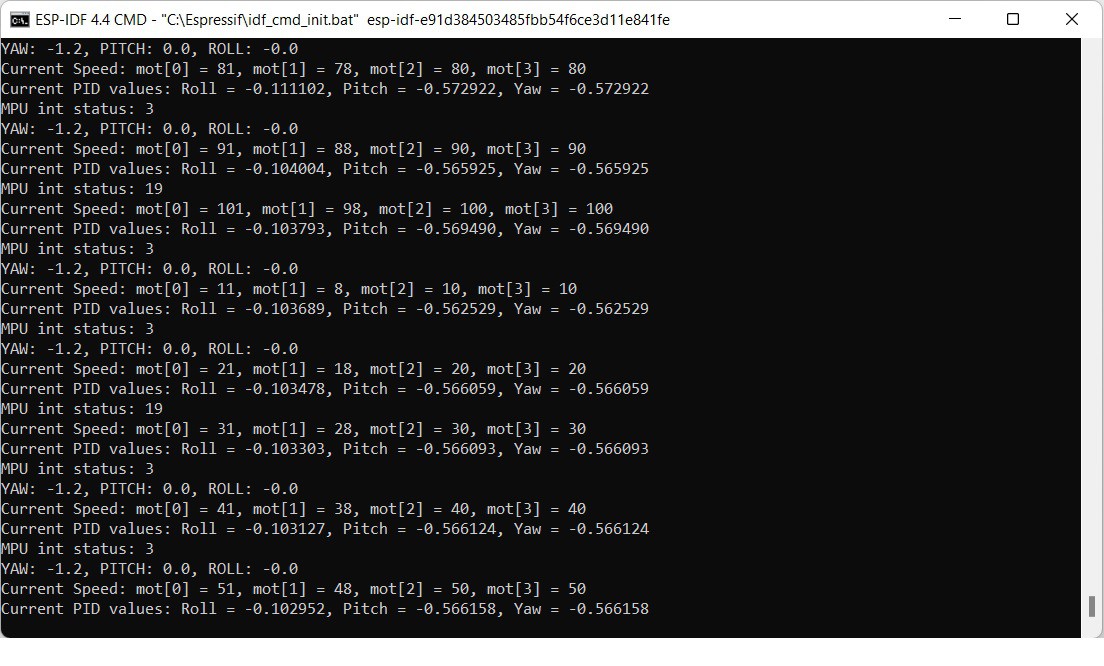
With the code and hardware sorted out, gave it a shot and flashed the firmware to the ESP. The output looked good to me sitting stationary on my work bench.
![]()
With that, I'll wrap this up, still got a bit more to do. Need to add the camera and communication code to this project and it'll be near completion along with a test flight and maybe some video to follow. Along with some build instructions.
*sorry for the write up earlier need to proof read these before I post them.
-
MPU magic and starting to pull things together.
12/11/2022 at 20:27 • 0 commentsAlright, so I got to looking at the Arduino build code for the motors with PWM and... of course the PID and MPU6050 were all coded in together. What I ended up doing was working on the gyro first.
What I had to do was find a library that would work with the MPU6050 and the ESP-IDF build environment. Luckily, there was such a thing, that's here and I wasn't going to have to start from scratch. Also, it has an awesome little test example which I could use to to do a function check really quick.
I did run in to an issue with the example, nothing ever works perfectly on the first try. If it does that generally tends to worry me as there might be an issue further on down the line. The issue was with their sdkconfig file. They seemed to have some different boot image options enabled for a different board that wasn't going to jive with the current board I am using for this build. So, being the lazy person I am, I just copied a version of the sdkconfig that I had from a different project over to it and that seemed to fix the boot image issue that I was having.
Great Success, yes! got some good initialization messages along with some good telemetry data.
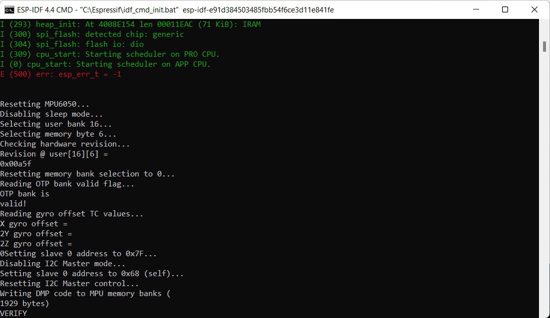
MPU6050 being initialized:
![]()
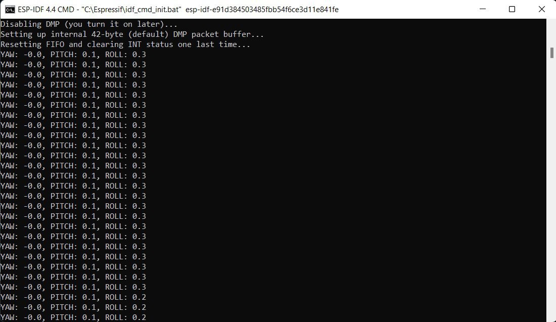
MPU6050 telemetry data:
![]()
Good stuff, I proceeded to see if there would be any issues with the gyro working with the camera. Since they both use the I2C interface. Which of course there was... Dug a little bit and with some critical thinking realized both the camera and the gyro both are using different libraries to use the I2C interface. Small brain move on my part I then remembered that the ESP32 has more than one I2C port, I2C_NUM_0 and I2C_NUM_1 so... instead of rewriting or scrambling to find something thing that would work with both of the devices. I opted to just use both of the I2C interface ports and save some time.
Doing this required having to change the SDA and SCL pin numbers for the MPU6050. SCL got assigned to 16 and SDA got assigned to 17. Also, since the library being used for the gyro is in C++ I had to add a header to the example and a little #ifdef __CPLUSPLUS magic so my C could see the functions in the object files that were compiled in C++.
Related header file:
#ifndef EXAMPLE_H
#define EXAMPLE_H

#define PIN_SDA 17
#define PIN_CLK 16

#ifdef __cplusplus
extern "C" {
#endif

    extern void task_initI2C(void*);
    extern void task_display(void*);

#ifdef __cplusplus
}
#endif

#endif
With that out of the way, it appeared to work correctly. Got a good initialization from the camera and also the same from the gyro along with telemetry data.
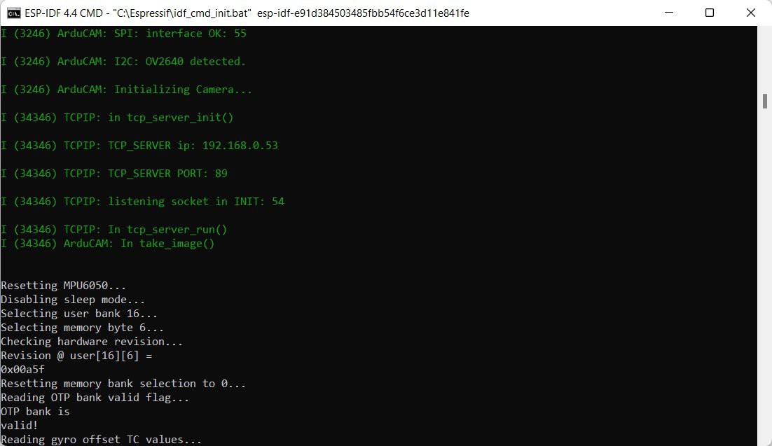
Camera initialization and beginning of Gyro initialization:
![]()
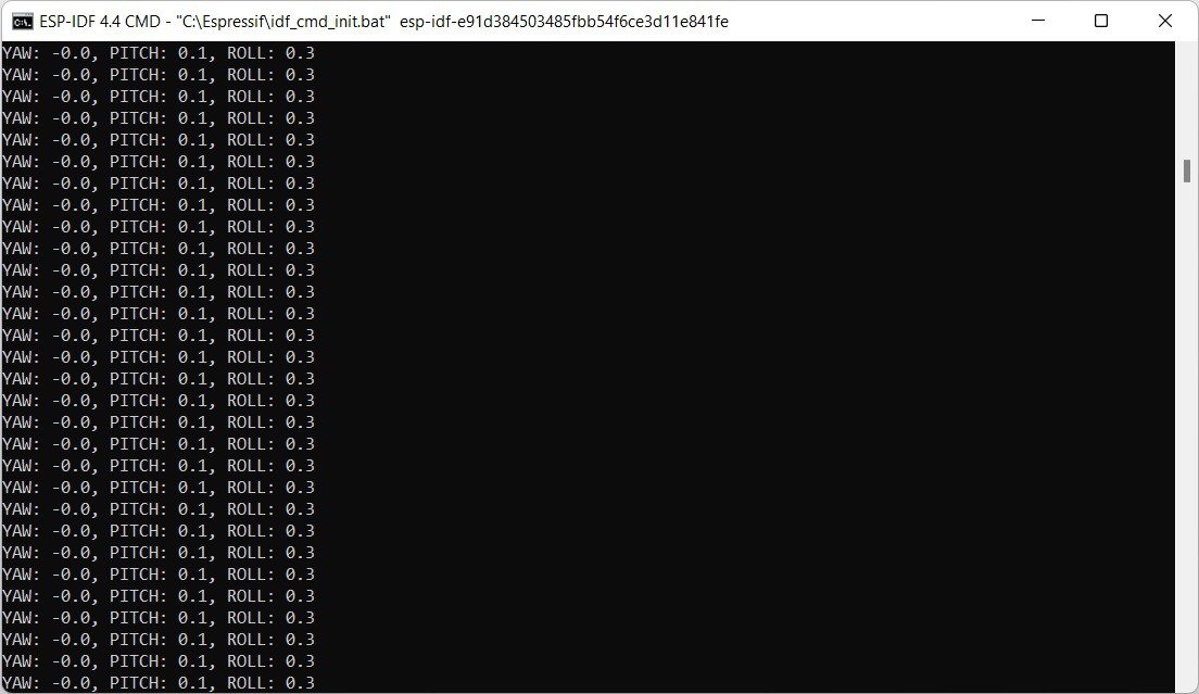
Some Telemetry data:
![]()
with this I just wanted to function test that both the camera and gyro would work together with out any issues which appears to be the case for now.
For the rest of the day I will probably be working on getting the code for the PID and PWM for the motors working, if there's enough time in the day I will see if I can get the gyro, PID and PWM all working together on the same thread. We'll see if I can get that far.
-
Trying to get things in order
12/09/2022 at 16:39 • 0 commentsI have a list of things I need to do in order to "complete" the project by Jan 3 dead line or get it as close as possible by that time.
- Get code unified and ported over to Espressif's ESP-IDF. I have most of the code for GPIO PWM for the motors and Gyro already done but under Arduino's build environment for the ESP32.
- Figure out how I'm going to get the PID control for the Drone that works in conjunction with the gyro into ESP-IDF. I have not even looked into this yet, as I've been down some other rabbit holes recently with this project.
- Get hardware setup for testing in step's to work with new ported code. Going to have to get bread board setup for testing motor's and gyro again...
- As I figure out more that's needed I will add to this list.
Was working on a menu interface for the Android portion of this build to make it easier to connect with the ESP, For now at least, thinking I'm going to put this on hold and leave as hard coded. This just has to do with the IP address and port number for the TCP side of things.
For today, I just want to try and get the GPIO PWM code written up for ESP-IDF and maybe test with the motor's if I got time to do that.
ESP32 Drone
I wanted to make a low cost drone with all the bells and whistles, so people working with a small budget can get into the drone game. ~$50