Christopher Xu
-
New boards sponsored by PCBWay
01/28/2024 at 22:04 • 0 commentsThank you to PCBWay for finding this project on here and offering a sponsorship! A majority of the cost of this revision, including the boards, components, and assembly, are paid for by PCBWay. Saves me a lot of time placing the components by hand!
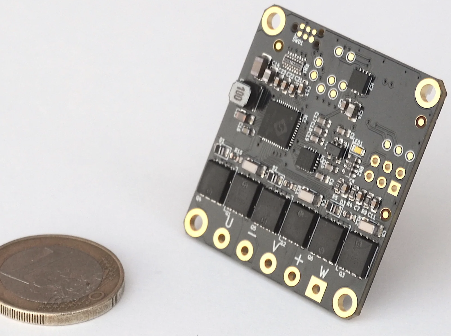
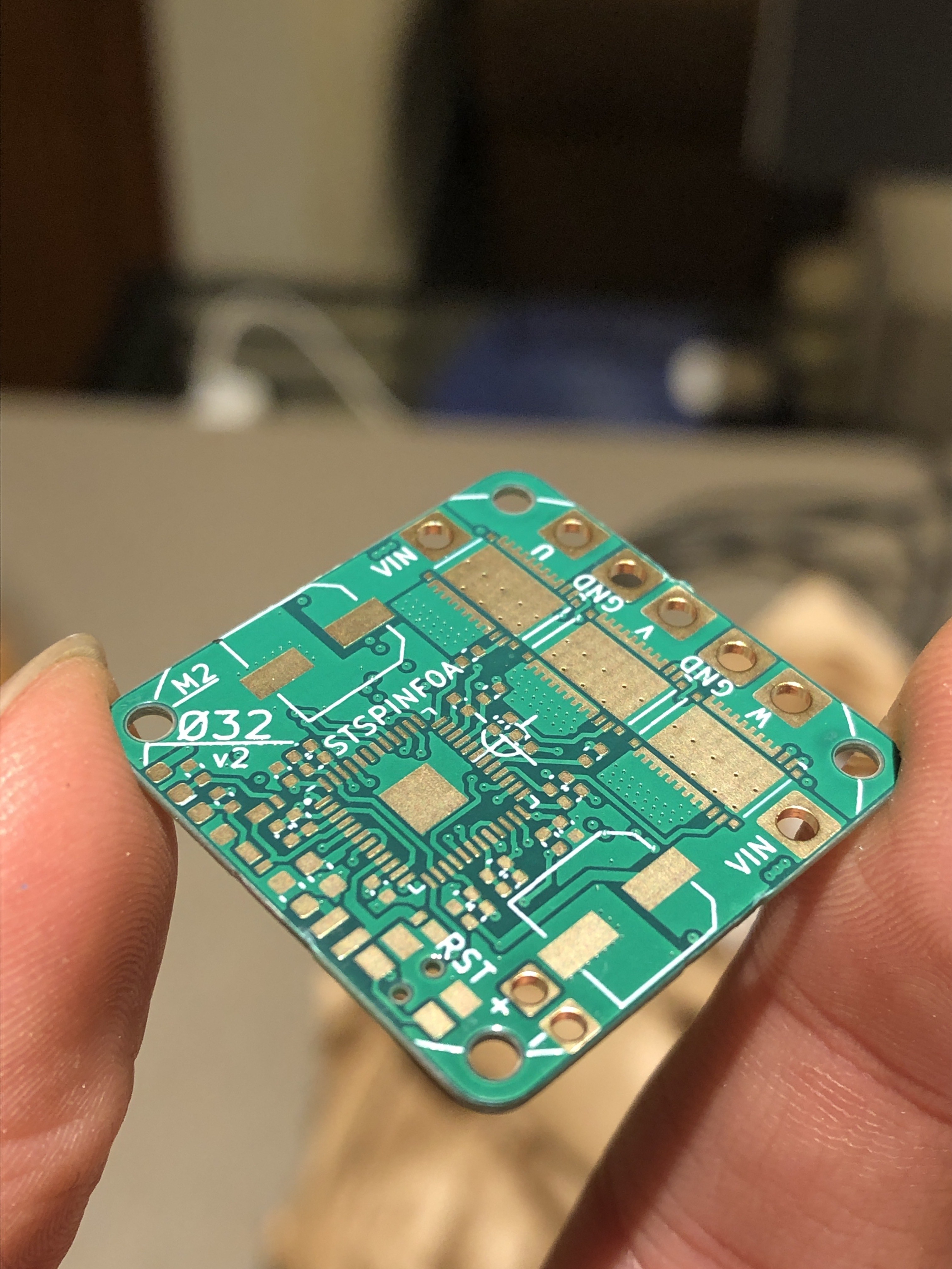
![]() This version is shorter, has an external SPI port, and NTC thermistor port. I don't have the firmware completed for external SPI and the thermistor, but I'll post another update if my project requires them (very likely the thermistor).
This version is shorter, has an external SPI port, and NTC thermistor port. I don't have the firmware completed for external SPI and the thermistor, but I'll post another update if my project requires them (very likely the thermistor).Changelog from v2 to v3:
- Fixed TVS diode direction on VBUS (!!)
- Changed to 37x 22uF ceramic capacitors instead of 2x 100uF electrolytic capacitors for a thinner PCBA
- Removed I2C (formerly on PB6 and PB7)
- Moved UART_TX and UART_RX to PB6 and PB7 (formerly on PA2 and PA15)
- Changed PA2 to ADC1 CH2 to read a 10k NTC, soldered to pads
- Changed PA15 to GPIO for external SPI CS (MAG2_CS)
- Added 13.7k pulldown on SPI_MISO to keep it determined when no devices selected
- Changed to 100nF filter capacitor on BUS_SENSE instead of 1nF to charge ADC capacitor better and for smoother data
- Changed BUS_SENSE gain to 5x instead of 5.12x to reuse 13.7k resistor
- Removed test point on BUS_SENSE
- Added test point on LED_STATUS (for debugging using GPIO)
- Removed NRST pushbutton to create space
- Added 6 pads with 0.5mm pitch to solder FFC cable for an external SPI encoder
- Changed vias to 0.25mm hole size and 0.55mm plated diameter instead of 0.2/0.5 for easier manufacturability
- Changed minimum track clearance from 0.2mm to 0.16mm to make space for larger vias
- Changed to equal number of vias (27) on the top side of all three shunt resistors
- Changed most silkscreen text to 0.8mm width/height
- Put all footprints and 3D models in project library O32controller
-
FOC implemented
11/21/2023 at 23:13 • 4 comments![]()
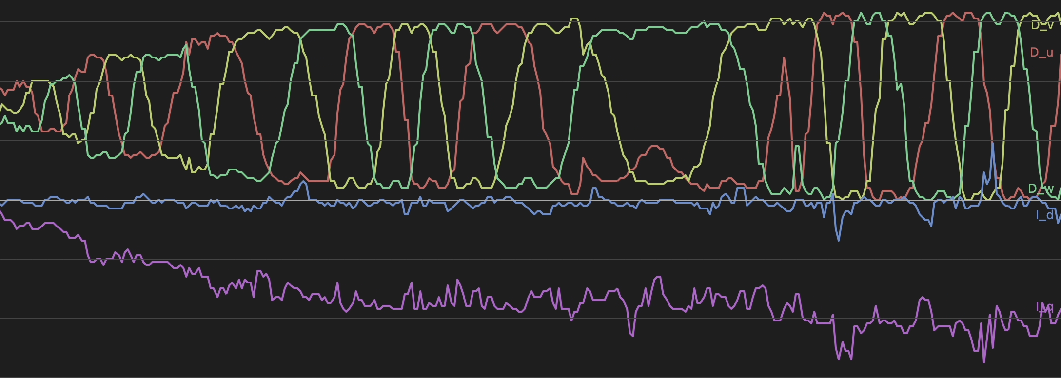
I had a joystick control the desired quadrature current, and the controller is able to track the desired I_q while keeping I_d at near zero (plotted in blue and purple).
Red, yellow, and green show the duty cycle of each motor phase, and you can see the space vector modulation (SVM) waveform change magnitude or frequency depending on the desired current and speed of the motor.
-
Daisy chaining
08/27/2023 at 17:30 • 0 comments![]()
![]()
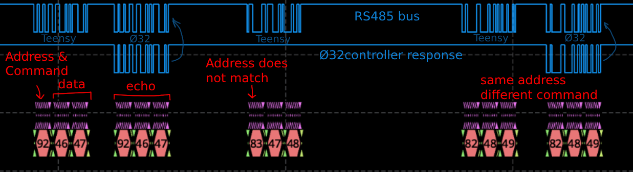
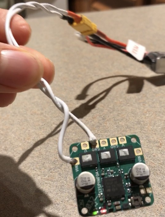
One feature of this motor controller is that it has two power and two RS485 ports so it can be easily daisy chained with other. This week I spent a few days developing a simple 3-byte serial protocol that allows for bidirectional communication between multiple motor controllers and a master device (Teensy 4.0) for messages like set voltage, set current, get position, etc. It's like CAN, but I had to make do with a microcontroller without a CAN peripheral.
The goal is reduce the number of wires running along a robot, especially for serial linkages. The limit is currently around 4 motors in series at 500Hz because only a certain number of bytes can fit within a certain time frame and all the current passes through one board, but I think it's worth the wiring convenience.
Also, here's the robotics project I'm using these for: https://pintobotics.substack.com/
-
Smooth commutation
07/02/2023 at 23:56 • 2 commentsA classic: using too many printf statements (over UART) that the code execution was taking too long and causing inconsistent commutation. Now it is spinning so much quieter and with more torque, at around 5200rpm. It should be able to go faster, I'm only applying about half duty cycle at the moment.
-
Spinning!
06/20/2023 at 05:39 • 0 comments![]()
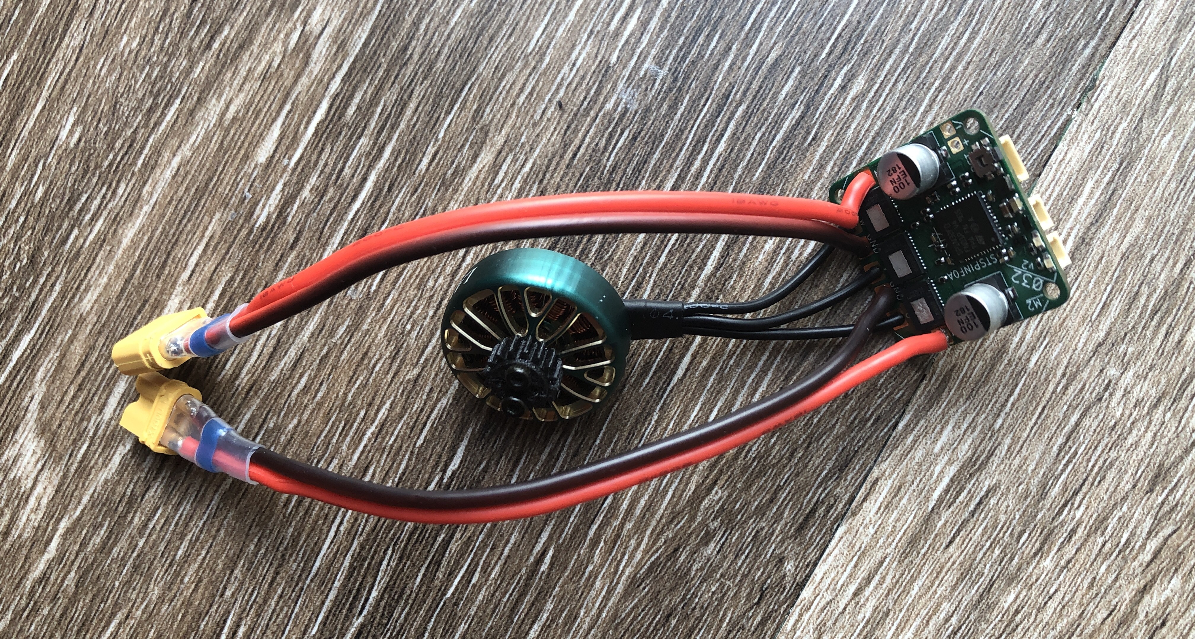
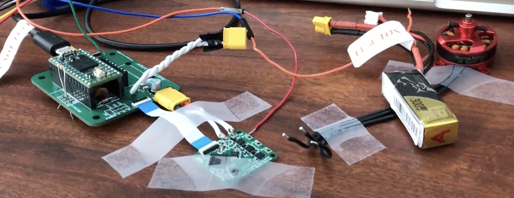
I got a bit distracted with other projects, but I'm back to developing this! I 3D printed a small stand for a motor and starting running the motor open-loop by simply iterating through 6-step commutation at a fixed speed and hoping the magnets in the rotor follow the generated magnetic field. It spins, so there are no major problems with the hardware. The MA702 magnetic angle sensor also works great, so next step is using the sensed angle to commutate properly. I'm delighted by the simplicity of the MA702. Just send 12 zeros, and you get a 12-bit angle in response, without any register operations.
-
Life
01/18/2023 at 06:54 • 0 commentsSafely powers up! Still waiting on the MA702 to arrive, but until then I’ll start on blinking the LEDs, communication with external MCU, and toggling the Mosfets.
-
01/14/2023 at 02:04 • 0 commentsI’m excited
-
Tinymovr
01/13/2023 at 20:26 • 0 commentsFound out about the Tinymovr motor controller. Basically what I'm trying to do! Very cool, and my version 2 will use it as reference. I hope to make mine even smaller (27x27mm vs 40x36mm) and cheaper ($40 vs €89). I only need up to 13V (3S lipo), while theirs goes up to 38V. Huge respect to their firmware too, lots of features there.
![]()
-
The past
01/13/2023 at 20:17 • 0 comments![]()
This project started when I tried to make a jumping robot. It jumped, but the servo seemed weak for its weight. I looked into brushless motors, but existing drone and car ESCs did not have the positional accuracy at low speeds and the more complex sensored motor drivers like the Odrive were too bulky, and also expensive. So, I tried to make my very first PCBs:
![]()
The motor driver board is the small one on the right, designed to fit behind the red motor. The larger board serves as the main controller, and this main board can control up to two driver boards. I based my design on the RAA227063 gate driver IC, and the PWM commands must be sent from the Teensy 4.0 on the main board. This worked, but only for a moment.
![]()
With any load, one of the high side mosfets would be burn out, ending up with the gate shorted to drain. I replaced the mosfet 2 times, with the same failure. After some crude probing I believe this was the result of ringing on the gate, because I didn't put a resistor between the driver and the gate, and the trace was probably not routed optimally. Next version, I'm adding a gate resistor and making it a 4-layer board, hoping that the extra ground planes will decrease parasitic inductance. There will also be RC snubbers on the output in case.
Ø32 BLDC Controller
Miniature closed-loop controller for brushless DC motors