Close
0%
0%

UChaser - Ultrasonic Following Control System

An embeddable control system for creating robotic projects that follow a target.

Similar projects worth following
UChaser is the incredible evolution of a project that spanned 11 years. Our first creation, Robot Luggage, was a marvel in its own right. Now, with UChaser, we embark on a new chapter. The system comprises of a lightweight target and a receiver that listens to the target's signals, precisely calculating both distance and angle. Armed with this information, the UChaser's control system can effortlessly trail its designated target.

Our ultimate ambition for UChaser is to craft a resilient and user-friendly sensor system that is effortlessly adaptable to a wide range of small electronic vehicles. By seamlessly integrating this technology, users can experience the thrill of autonomous driving, as their vehicle faithfully follows a designated target, leaving them free to focus on their journey.

Step into a world where innovation and companionship intertwine, as UChaser paves the way for a future where personalized following robots enhance our lives in unimaginable ways.

Working principle

Here's a description of how this works.

  1. The transmitter sends a radio signal and an ultrasound signal to the receiver.
  2. The radio signal arrives first, the receiver starts counting from that moment until the ultrasound signal arrives.
  3. The receiver records the time that the ultrasound signal was received on the right and left receiver.
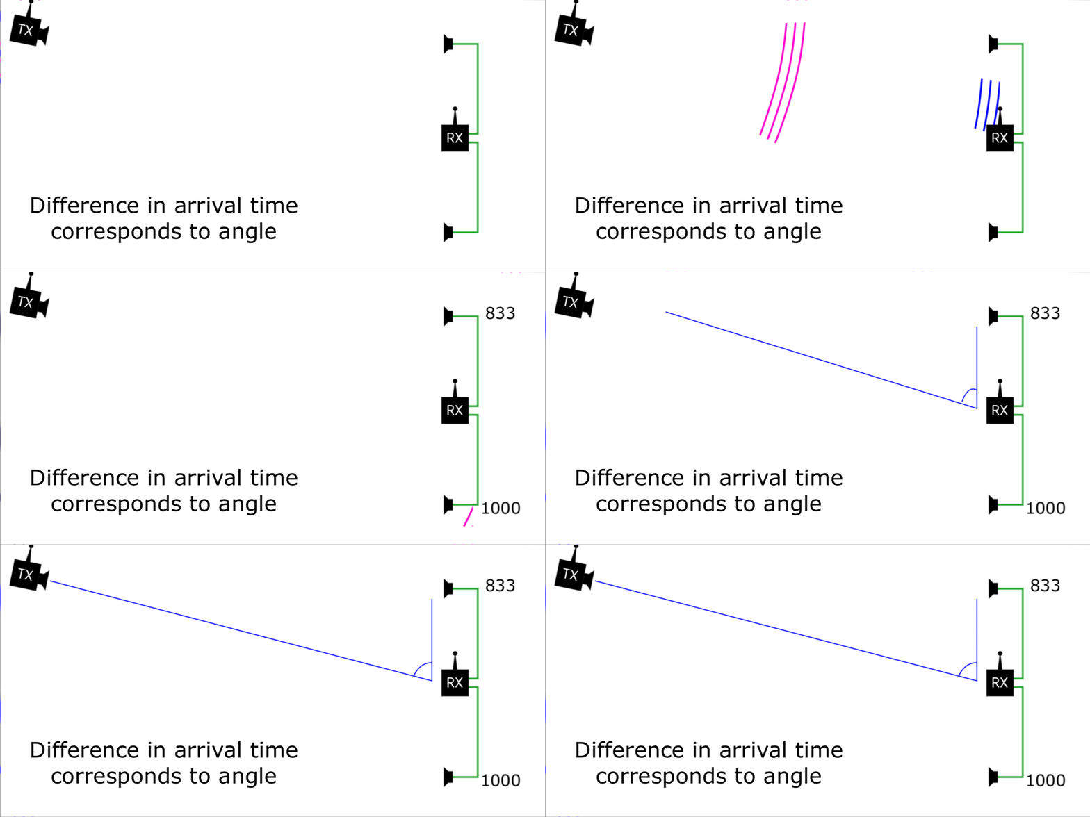
  4. The angle is calculated based on the difference in arrival between left and right ultrasound receivers.
  5. The distance is calculated based on the difference in arrival between the radio and ultrasound.

Here are a couple of animations to help explain:
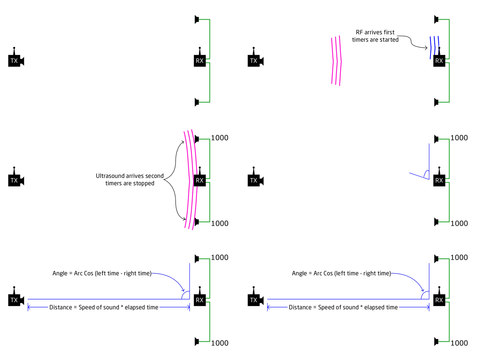
When the ultrasound signal arrives at the same time to both receivers we know that the transmitter was directly ahead.  When there is a difference we can tell if it is to the left or right:
Watch this video of it in action using off the shelf hardware prior to rolling our own:

  • Github Repository Added

    Jesse R05/11/2023 at 17:46 0 comments

    Github repository added with our code and hardware files.

    A note about the hierarchy:

    Prototype - contains code for the main controller board, TX hardware rev 1, RX Hardware rev 1 and 2

    Receive MCU - is our mainboard for the receive side, but we are also using it to do our transmitting until we have that little board designed

    Receive US - has our rev 1 and rev 2 receiver boards.  There are two sets of rev 2's because we had two different layouts to try, we ordered them both. Rev 2 needs some work to be functional.

    Transmit US - has our rev 1 transmitter board, the board we are still using today

    Here are links viewable without KiCAD thanks to the awesome work of Stargirl on KiCanvas!

    Receive MCU

    Transmit US

    Receive US - rev1 - does not show our mods, see log on hardware

    Receive US - rev2 - not currently working, troubleshooting

  • ESP-NOW timing uncertainty

    elliotmade04/18/2023 at 23:59 0 comments

    As we mentioned before, we're using the ESP-NOW protocol for our radio layer.  The primary purpose is to synchronize the two devices and give the receiver a reference point to use in calculating distance.  A second benefit is that we can "squelch" the receiving transducers until we are expecting a signal to show up which helps avoid random triggers.  ESP-NOW is lightweight compared to full blown WIFI, and Espressif even advertises it as having "millisecond-level" delay for an application like a remote control - this is all fine.  In our application, however, the consistency of the timing is more important than the overall latency.

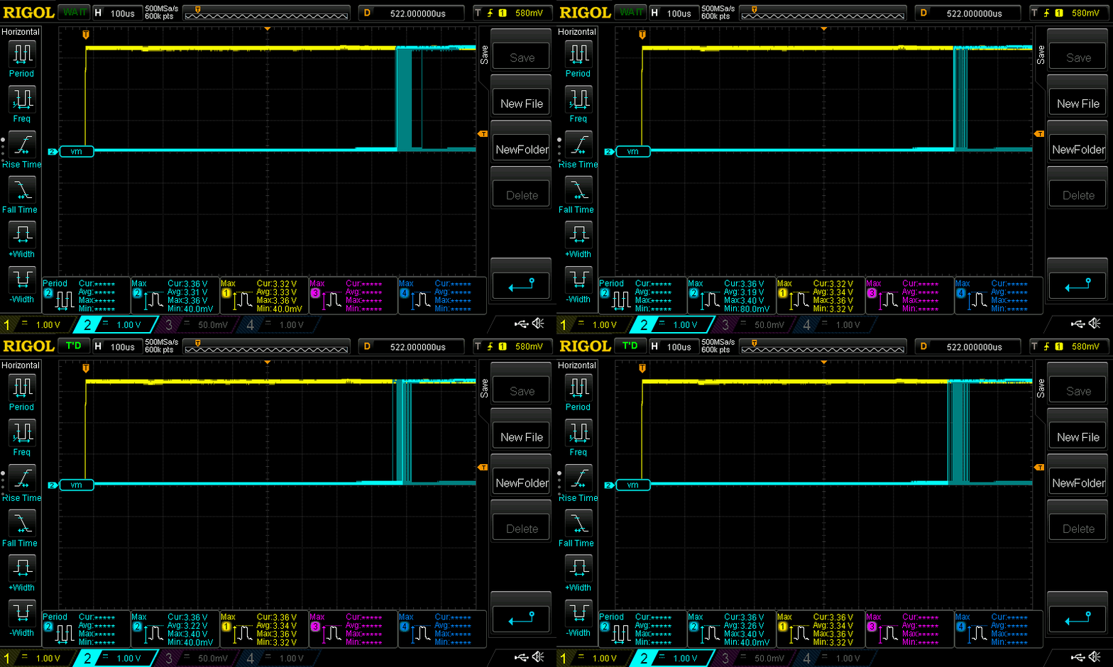
    In this image the yellow edge is triggered by the transmitting device, and the blue edge is a pin on the receiving device that is pulled high when the message is received.

    As you can see, the time between the two edges is not completely consistent.  I believe there are a variety of reasons, but the main one is that the protocol doesn't operate in real-time like other code does, meaning that the time between receiving the signal and processing the data is not deterministic.  It looks like the variation falls inside a 60 microsecond window, with the occasional (1 out of 100ish) even that deviates by a few hundred microseconds.

    In practice we think this is good enough:

    343 m/s (speed of sound) / 1000000 microseconds/second = .000343 meters/microsecond

    .000343 * 60 microseconds (variability) = .020 meters

    Having 20 mm of uncertainty is pretty acceptable for the applications we have in mind.  This wouldn't make a great ruler, but the error from this source is probably less significant than other issues like line-of-sight and echoes.  We can also clean this up with some averaging in software.

    On the bright side, this only affects the distance measurement: the angle measurement only compares the arrival of the two ultrasound signals to each other.

    Why not use something better?

    We might be able to use an external radio and a proper interrupt on one of the ESP pins to mitigate this issue, but here are some reasons we haven't (yet):

    • No additional components needed
    • We can encode additional information in the packet, a stop/start signal for example, or data to implement a complete remote control
    • It's easy to use an implement
    • It doesn't affect the angle measurement
    • The result is good enough

    That's all for this one.  We can see how this affects the real-world results later.

  • Ultrasonic Modules - First Revision Custom Ultrasonics

    elliotmade04/18/2023 at 16:59 0 comments

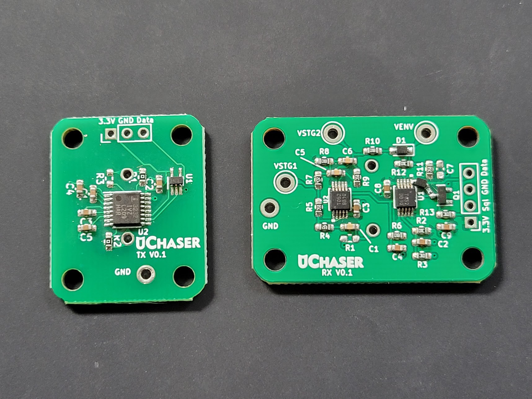
    First revision of our Ultrasonic Hardware:

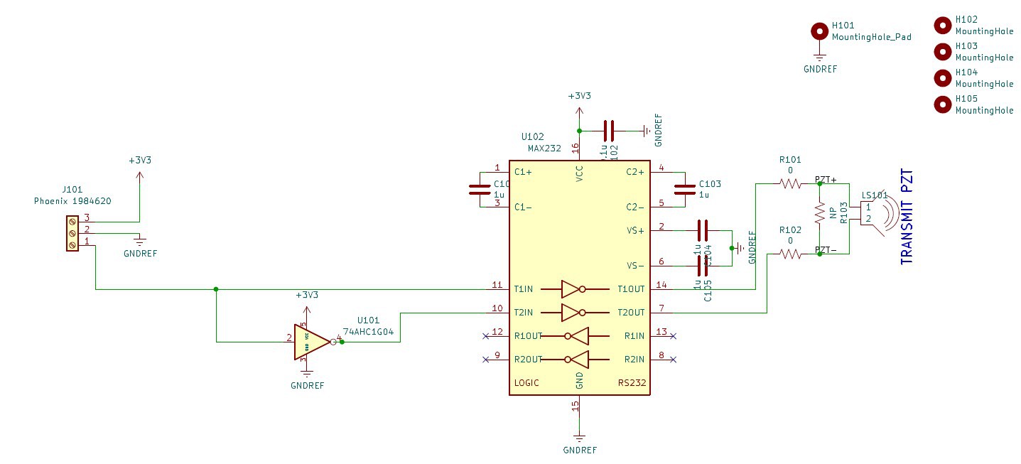
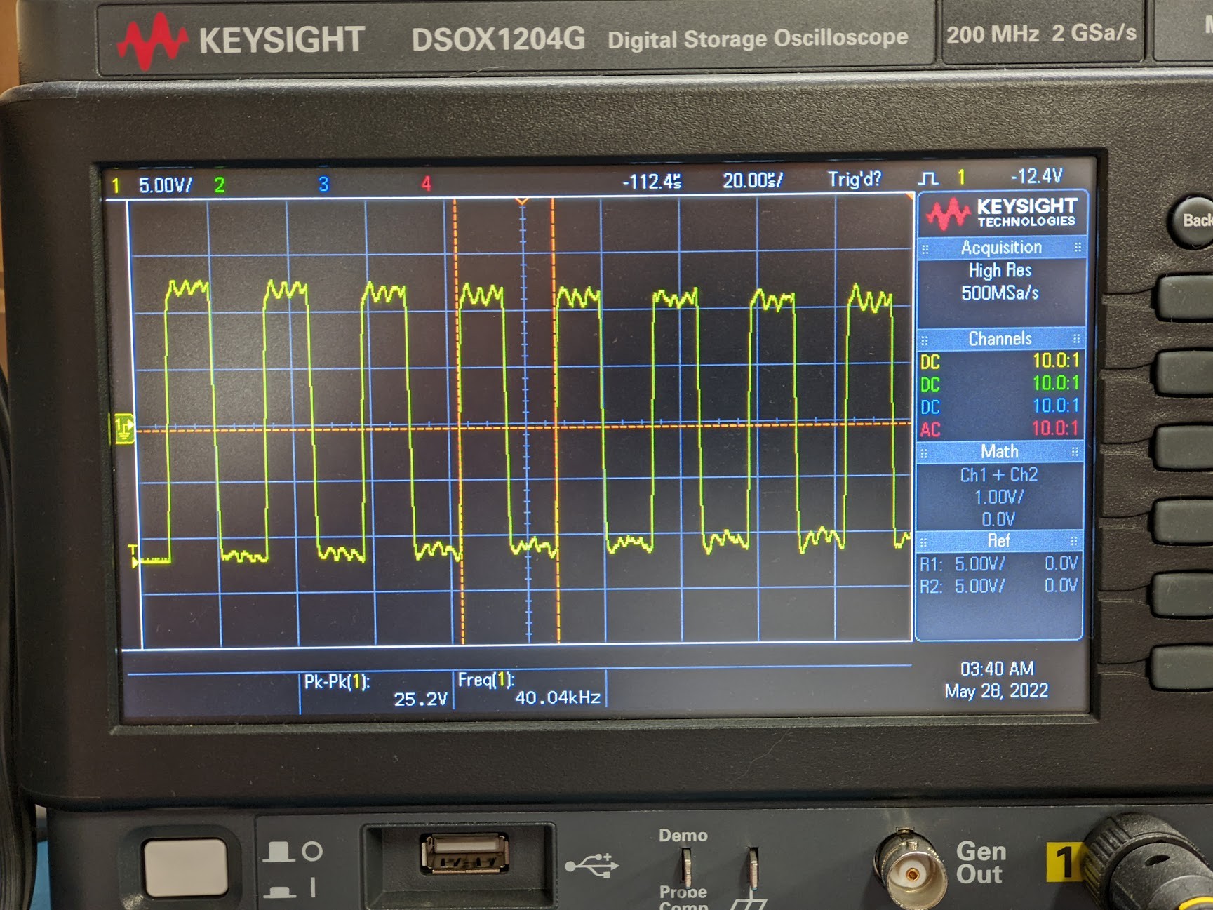
    For the transmitter we followed what we found of similar items on the market, like Sparkfun's Qwiic Ultrasonic Distance Sensor - HC-SR04 which uses an RS232 charge pump chip to turn the 3V3 input signal to a 20Vpk-pk excitation signal for the ultrasonic element.. Our circuit takes in 3V3 for power and a single trigger signal which it then inverts to drive the second transmit channel so when one is positive the other is negative which gives this larger full wave signal (double what just using a single TX line would allow).  There is some attenuation as the excitation signal goes on for multiple cycles, but when testing our transmitter with an off the shelf HC-SR04 receiver we didn't notice a range difference.

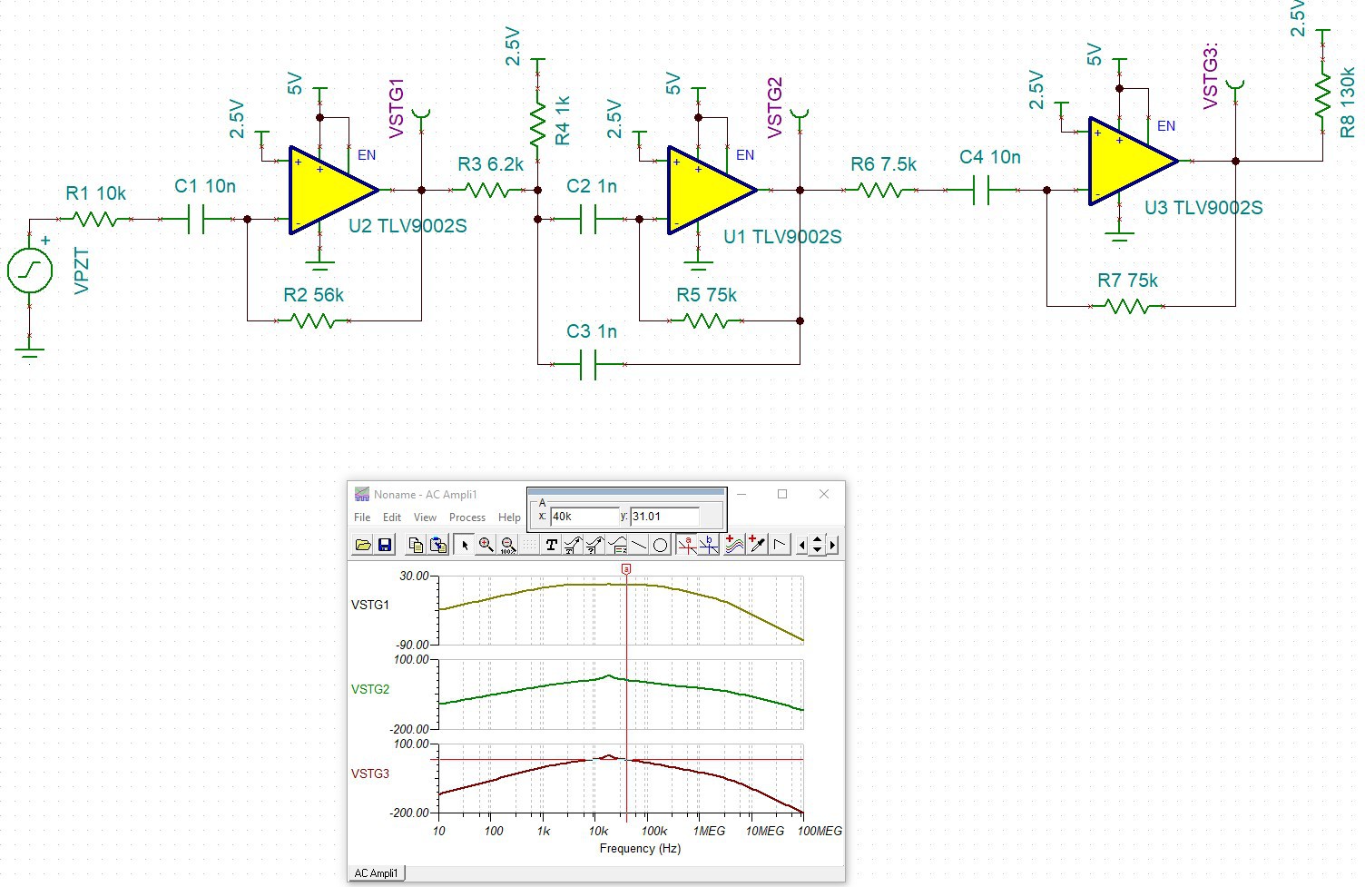
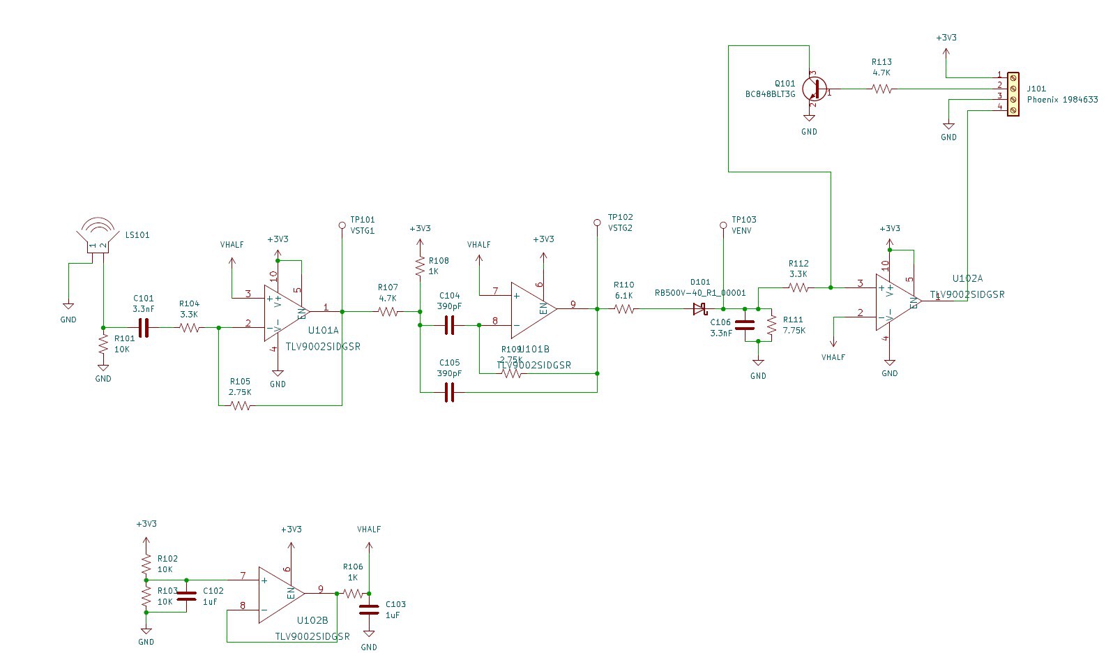
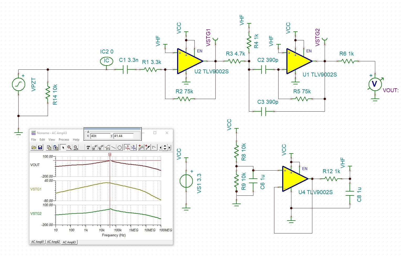
    For the receiver I started by finding a schematic of a standard HC-SR04 transceiver online and simulated it, finding the center frequency was around 20kHz.  I also wanted to add a buffer amp to the reference voltage as I've done in other projects but still keep only 4 amplifiers so I tweaked the gain and center point of the amplifiers to allow losing a stage.  I also changed the comparator stage to have an envelope detector as that worked well on my Ultrasonic UART project, and added an optional damp transistor on the ultrasonic element.  

    Here's the sim of the standard HC-SR04 design:

    And the schematic of our receiver:

    And SIM of the receive portion:

    In theory we should have been better, in practice we were not.  Our 30 foot range went down to 10 feet.  We even tried the ultrasonic elements from HC-SR04 boards in case it was the Amazon element I bought, but it did not change things.  Some of the mods I did helped a bit, like removing the damp resistor across the PZT, removing the capacitor after the envelope detector, and adding a one shot mode by feeding the output to the compare input, and those changes helped but didn't get our 30 feet back.

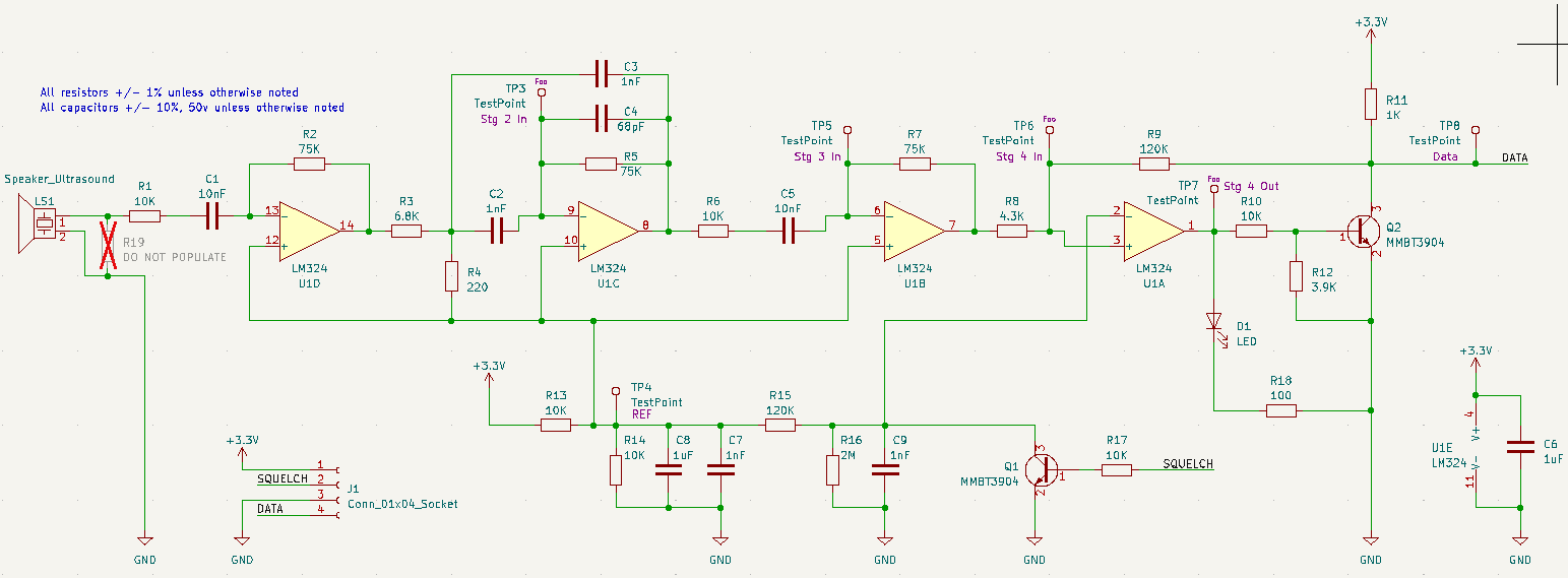
    So transmit boards were okay, but for receive boards we went back to a known working design and took a portion of the Sparkfun's Qwiic Ultrasonic Distance Sensor - HC-SR04 to create our next revision.  Boards are coming in prepopulated from JLCPCB.

  • More prototypes

    elliotmade04/18/2023 at 15:37 0 comments

    Here's a quick look at where we're coming from.  After the wheelbarrow POC the project has been on the shelf, this is what we've done recently.

    Breadboards

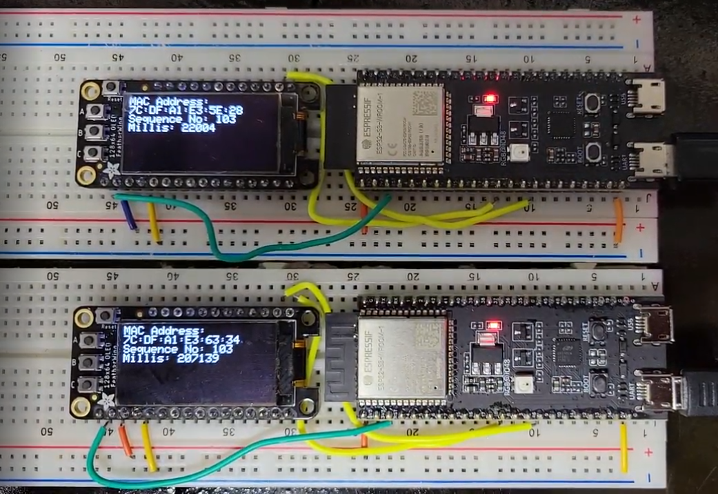
    We switched to the ESP32-S3, here are two devkit modules on breadboards:

    At this stage we have added an OLED for testing - the transmitter is sending a message over ESP-NOW and both modules are incrementing a counter in sync.

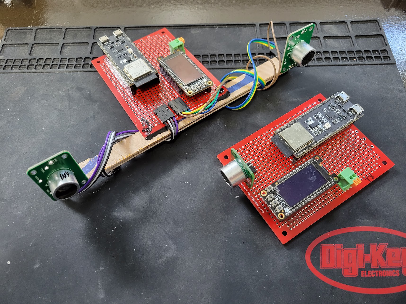
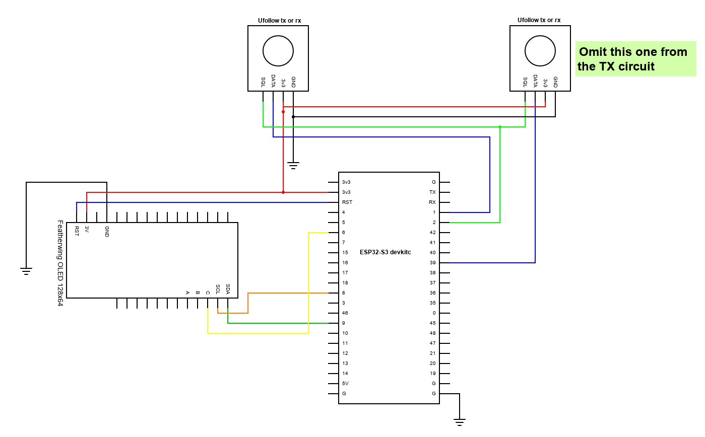
    Proto boards

    Moving on up, now we have the same modules in a slightly more robust assembly.  We have added our first revision of the transmit and receive transducer boards.  This setup is functional enough to measure angle and distance, but we found the performance of our receivers is fairly poor; detection falls off around 8-10 feet, as compared to the HC-SR04 module which was reliable to at least 30 feet.

    Next revision

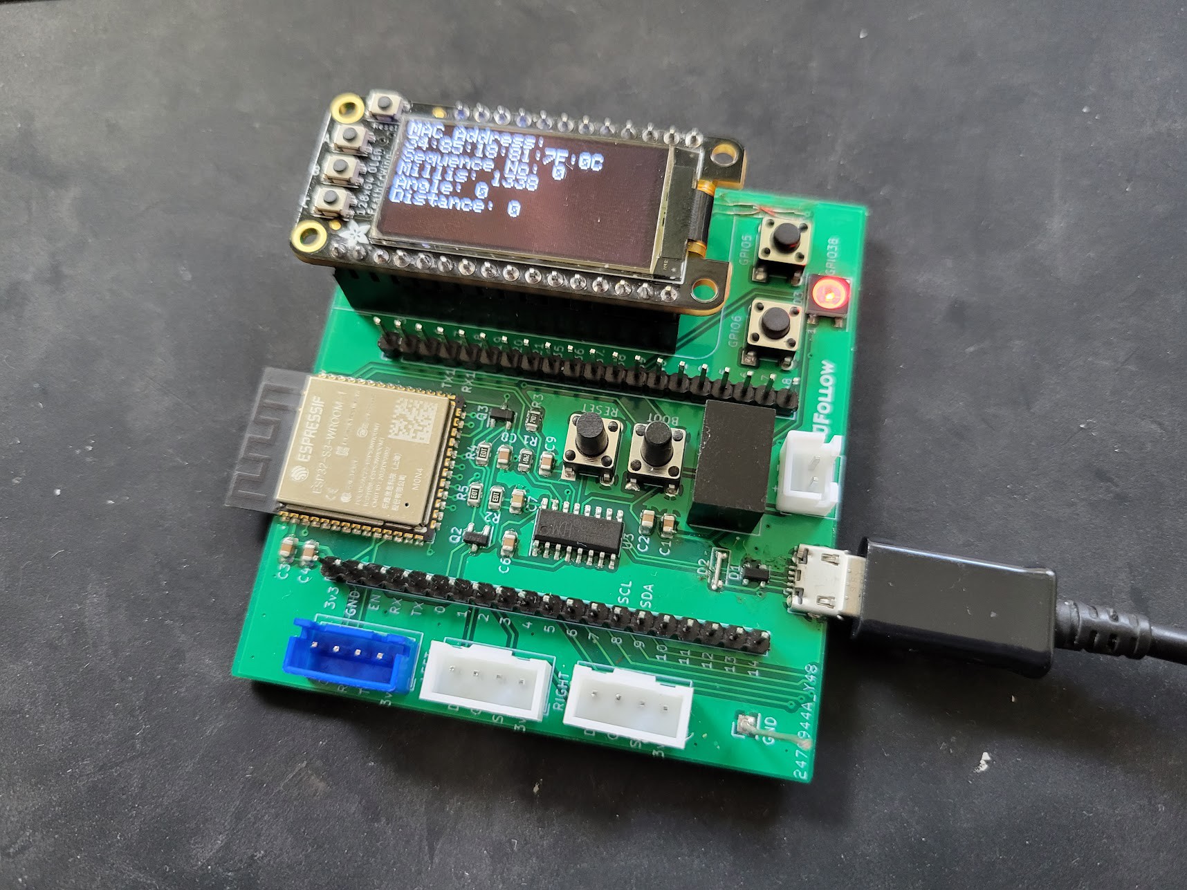
    Here we are graduating from the devkit modules, this gives us a chance to prove out or schematic and power supply situation.  It adds a few buttons and a RGB LED.  For now we are using the same assembly for the transmitter and receiver modules, in a future revision we will have a bespoke design for the transmitter that is suited to run from a battery and is more compact - the display here is still just for testing purposes, we don't plan to include that in our final product.

  • POC: a wheelbarrow

    elliotmade04/14/2023 at 18:54 0 comments

    Hey this is Elliot - I had a remote control wheelbarrow and thought it would be handy if it would follow me around the yard.  Using the same concept as Jesse's luggage I made up my own version about a year ago.  I used different hardware - this time a pair of ESP32s and three HC-SR04 ultrasonic rangefinder modules (the common Arduino starter kit type things). 

    The operating principle is the same as the luggage:

    1. Transmit a simultaneous radio and ultrasound signal from a beacon
    2. Receive the radio signal on the robot first, then start listening for the ultrasound signal to arrive
    3. Mark the time of the ultrasound signal on both right and left transducers

    Once I have these three timestamps I can do some math to calculate both the distance and the angle to the beacon. 

    The distance calculation relies on the difference between the speed of sound and the speed of light: if we pretend that the radio signal is instantaneous then on the receiving end we have a start time for the ultrasonic pulse that was sent, and it is simple to measure the time until it arrives.  Using the measured time and the approximate speed of sound we can calculate a distance.

    The angle calculation is possible without the radio signal at all, but I still use it to keep everything synchronized.  This works just like our ears - listening to two receivers (right and left), we can tell if something is straight ahead or off to the side based on which receiver hears it first.  With a known difference between right and left we can translate the time difference into an angle.

    Radio:

    Initially I used 433mhz radio modules but found them to have poor range and poor reliability; ultimately I used the ESP-NOW protocol for the radio signal because it looked easy - and that turned out the be the case.  Unlike proper WIFI there is no authentication or anything else, so it is quick and easy to set up.  It is limited to 250 bytes of data, but has the benefit of being able to use an interrupt when a packet is received.  There are some challenges with this approach over a pure radio setup I will discuss in another post.

    Ultrasound:

    The transmitter and receivers are the ubiquitous HC-SR04 modules.  The way these normally work is:

    1. Trigger the module and it sends out a 40khz signal
    2. It waits a short period of time then listens for the echo
    3. A single square wave is output where the duration represents the distance

    On the transmitter end this is no problem - we only care about sending the signal and can ignore the echo entirely.

    On the receiving end there is a challenge - the output pulse is only generated after the module has been triggered and sent it's own signal.  I removed the transmitting can from the board which eliminates generating more signals - this is easy.  The other problem is that the module doesn't listen passively - there is only a small window of time where it will respond to a signal (usually it's own echo).  The trick I used was to use the radio signal to trigger the receivers at the right moment - no pulse would be sent, but it would begin listening.  We will eliminate all this fuss in the future by designing our own receiver and transmitter hardware.


    At the end of all this the ESP just spits out two numbers over UART to represent the distance and angle to the beacon, mission accomplished.  I kept the code for deciding how to move on the robot, separate from the rangefinder.

    There are a bunch of other challenges to think about: line of sight, echoes and reflections, how to handle signal loss, angle resolution, timing variability (particularly for ESP-NOW), variability of the speed of sound in the atmosphere... that is for future updates. 

    There is some more information and code/schematics for this prototype here.  For now here's a video of this POC working (somewhat):

  • UChaser Begins

    Jesse R04/12/2023 at 17:41 0 comments

    A brief history of the Ultrasonic Following project, original records here:

    Descriptive Blog Post About Ben Heck Project

    I met Ben Heckendorn by winning a contest. After some discussion he invited me to collaborate on a project he'd being thinking about for awhile, luggage that follows you around, he called it Robot Luggage.  Several options were considered and I settled upon using ultrasonic time of flight differences as the operating principle. 

    The system consisted of a Target, which contained an ultrasonic sender, and a Receiver, which contained two ultrasonic receivers (ears) spaced apart.  The time difference between receiving signals would give an Error value which could be used to close a loop and control the direction of the Luggage towards the Target.  

    I was worried about an asynchronous setup between having rollover timers and missing signals on one or both ears so I decided to use a wireless link to start a measurement.  This was my first Arduino project which gave its own difficulties but in the end we had a working proof of concept that worked pretty well.

    The system used Parallax PING sensors modified for send or receive only functionality, XBee for the ultrasonic link, and various power supplies and controllers for the robot.

    The project garnered a lot of attention and even got a Hackaday Article of my blog post about my experience.  Over the years I've answered many questions in regards to this project, helping others replicate it, but it got harder as time went on because of our lack of documentation, the difficulty of the project,  and obsolescence of components we had used.

    I've wanted to revisit the project and make an off the shelf system people could embed into their projects more easily and enlisted a few friends from a discord server I was part of.  I worked with Elliot to add the system above to his electronic wheelbarrow as proof of concept to start our new system, see the next log for his project

View all 6 project logs

Enjoy this project?

Share

Discussions

Similar Projects

Does this project spark your interest?

Become a member to follow this project and never miss any updates