-
[T] Filament order and issue prevention strategy
10/06/2023 at 11:40 • 0 commentsSo I've listened to the entire series of Deckingman's multi-material series and the 2 things I remember from it are that:
- PLA hydrolizes in under 30 minutes using an off-the-shelf X-in-1-out hotend and between 30 minutes and 1 hour in his design.
- Materials that one may want to mix together (e.g. ABS + TPU) will likely result in very poor interlayer adhesion
TPU coating?
Now, I'm thinking that because this is a coaxial hotend and interlayer adhesion is predominantly a surface-to-surface interaction, I could possibly have a transparent, flexible filament like TPU as the final coat. It shouldn't slow down the print speed as only small quantities would be needed, and TPU has one of the best interlayer adhesion properties of printable filaments, as well as bed adhesion to PEI.
To put it another way, this is the "glue" or "motar" filament. It also hopefully keeps the interlayer adhesion consistent even amongst different colours of the same material type.
If colour (and flexibility) is of little importance to the application, PBT filament may be ideal due to it's allegedly high Tg, stiffness, interlayer bonding and low required bed temperature.
Cleaning filament
Regarding the first point, I'm thinking that the cleaning filament should be the first input, allowing the printer to clear out the center column of the coaxial block as well as make material changes easier.
Park and reprime
Additionally, I'm thinking that the most straightforward solution to prevent potential issues is to just park the extruder every 40 minutes or so and fully reprime the hotend. The most optimum way would be to only purge the inputs that haven't been used frequently, such as any filament that hasn't been used for at least 5-10% of the duration between the last purge and now.
The rest of the lineup
I was partially wondering what I'd be using 8 inputs for, but now that I've thought about it, it's barely enough. This would be the lineup for full colour and alpha channels:
- Cleaning
- Transparent PETG
- White PETG
- Yellow PETG
- Cyan PETG
- Magenta PETG
- I've ordered 2 - 6 from most to least sensitivity to the human eye. Less sensitivity equates to less preception that a colour is right or wrong. I'd imagine it's a lot easier to see a small streak of yellow on white than a small streak of yellow on magenta.
- Optional / Speciality (e.g. Galaxy Black, Copper, Marble, Soluable)
- If black isn't used, the 3D print is likely going to have the same kinds of "blacks" as an LCD screen, which is just a dark grey. OLED inky blacks will need a black filament here.
- Glue (Likely TPU)
Conclusion
I think it's a good enough strategy to try, and I've modelled in a variety of improvements and discoveries over the years from the community to at least have some indication that this hotend would improve on the work.
Unfortunately, like some 2D colour printers I hear about on the internet, you actually won't be able to successfully print if you're out of cyan yet just want a B+W 3D print 🤭😅 (or something in that input).
-
[E1][M] Added components to 8 in 1 out hotend
10/06/2023 at 09:33 • 0 comments[10:30]
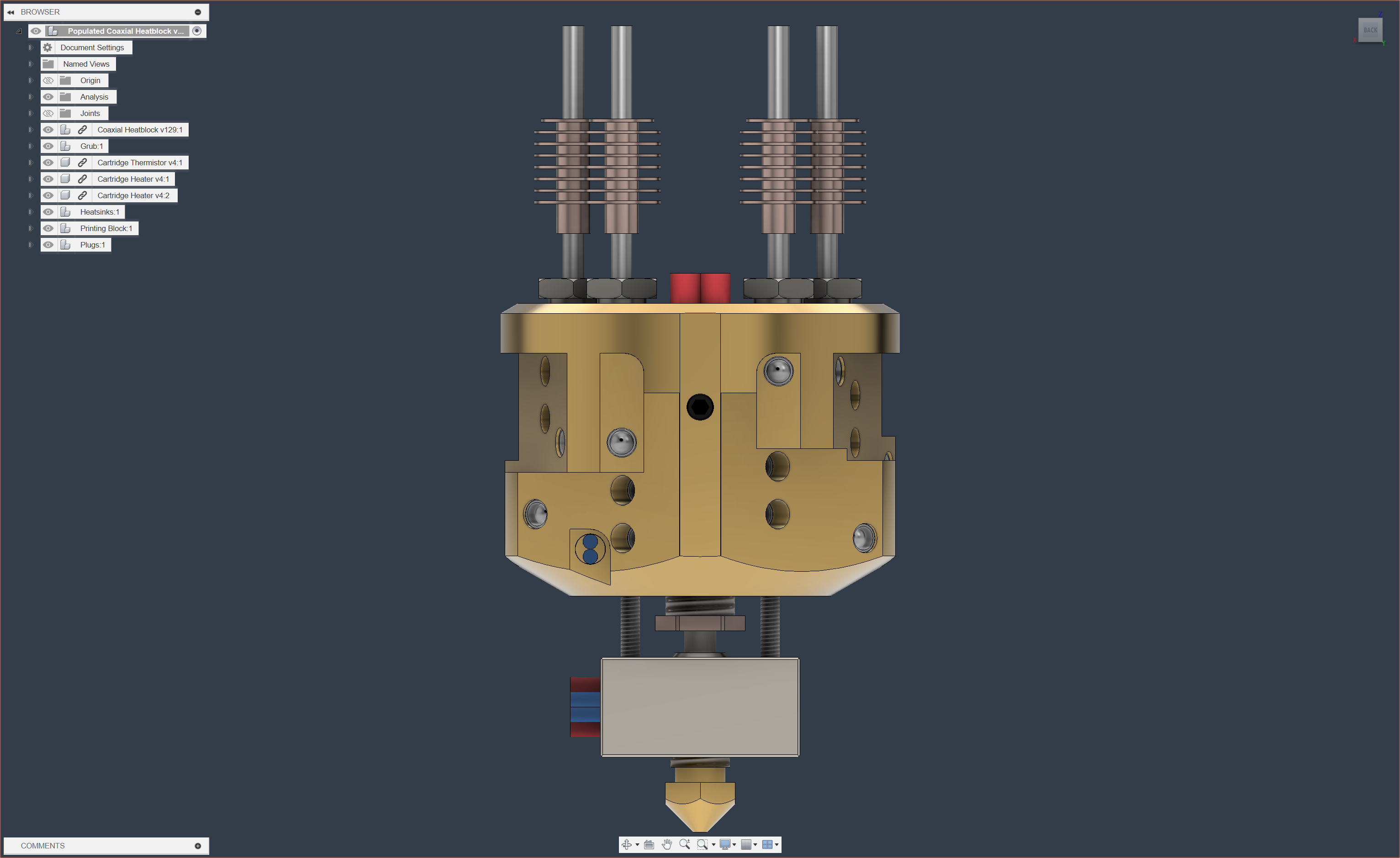
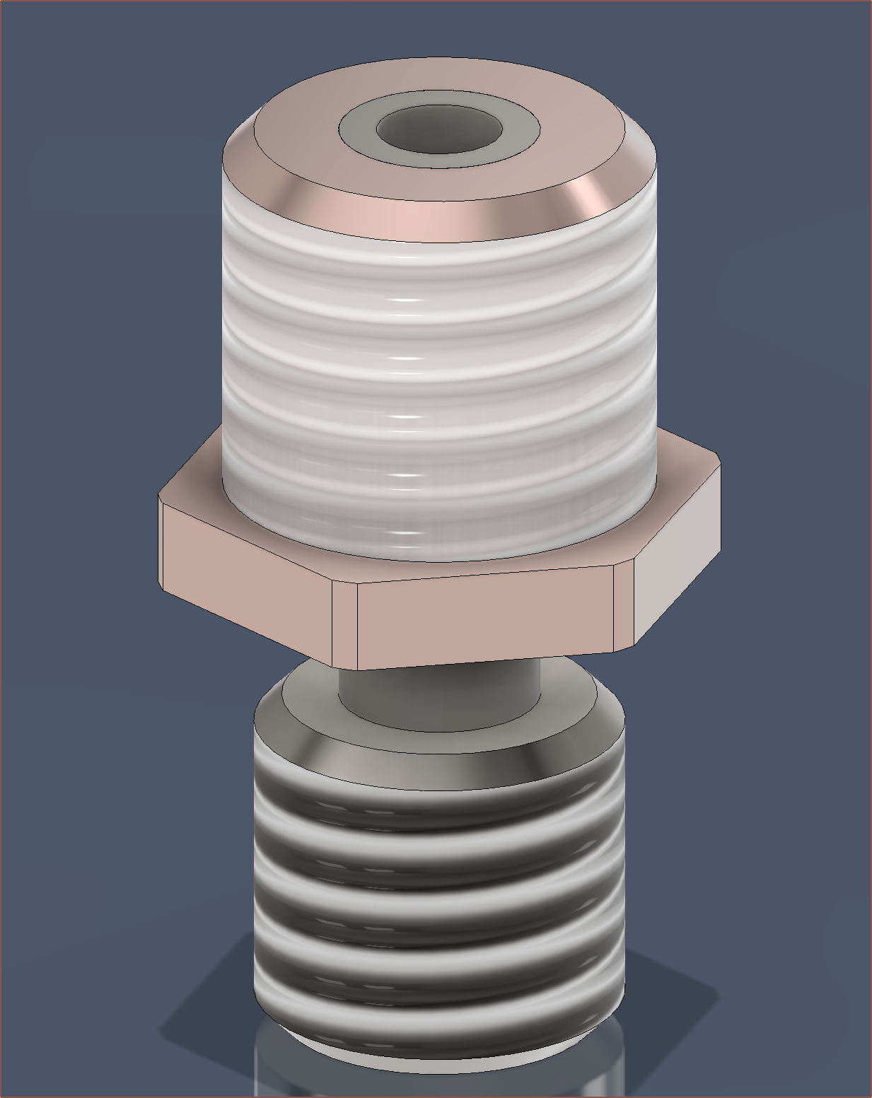
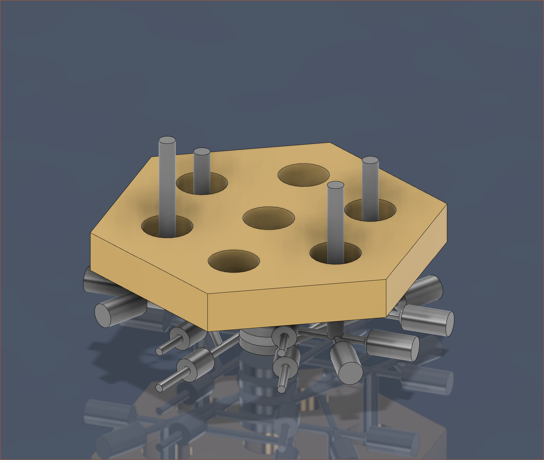
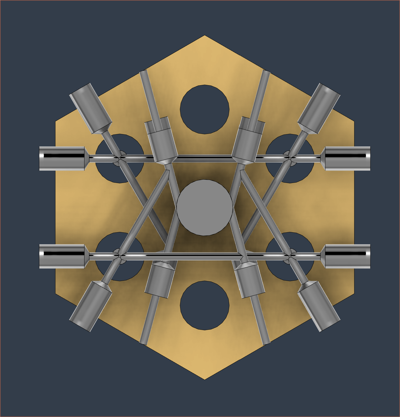
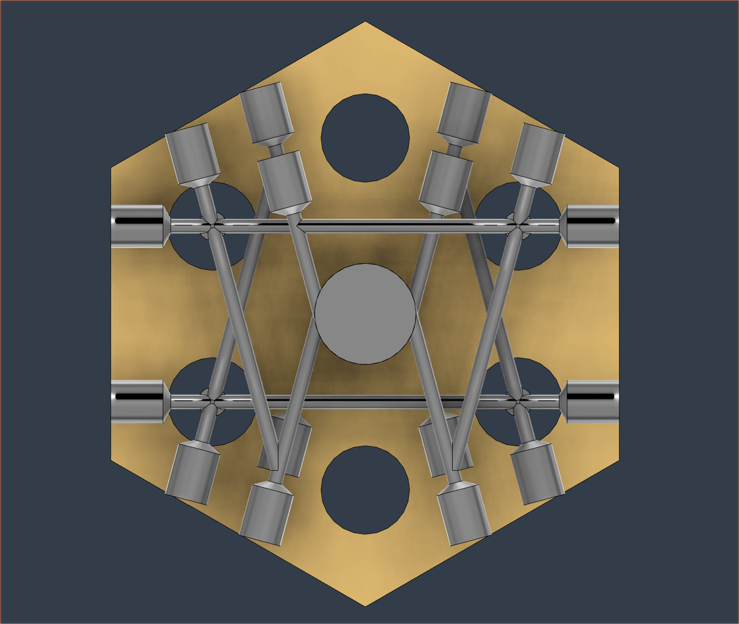
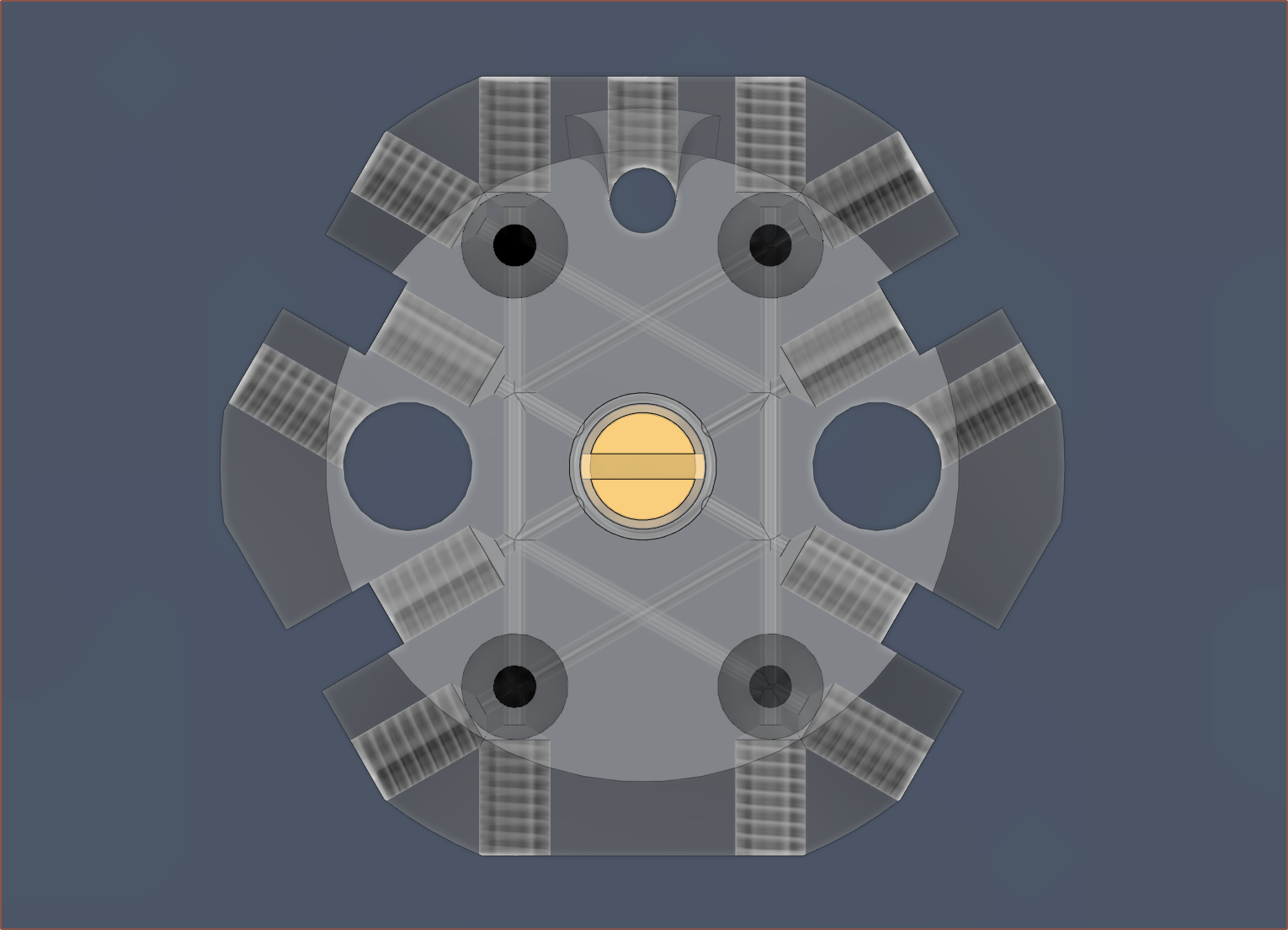
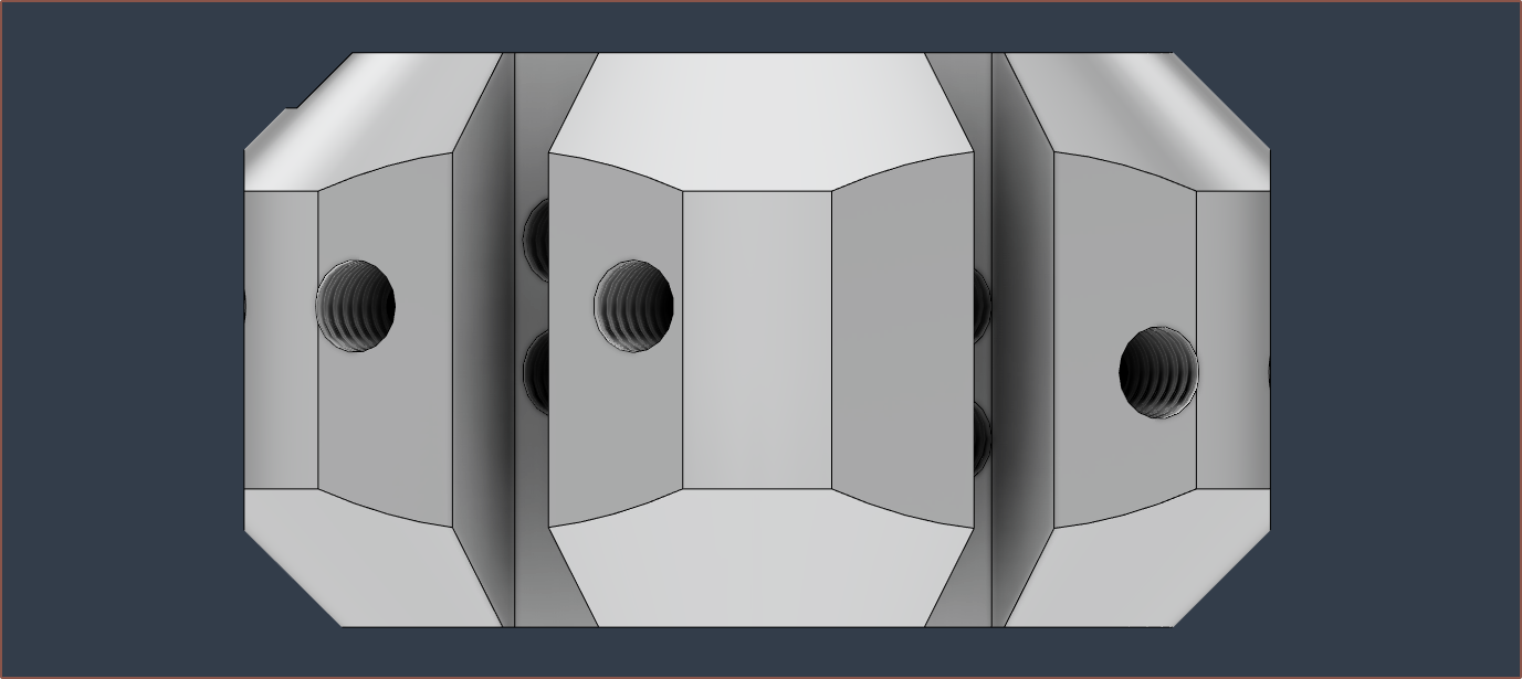
The max diameter of the hex on the heatbreak model I found on GrabCAD was 8.1mm, so that meant I needed to increase the distance between them to 8.25mm. It's a small change but seems to have had a large visual difference on the faces of the coaxial block.
Additionally, since the entire length from the bottom of the threads to the bottom of the hex is 4mm, I needed to reduce the M6 thread depth to 3.5mm to ensure that the hex didn't interfere with sealing.
I was unconvinced that I'd get enough thermal seperation using the volcano nozzle, so I modelled up the E3D V6 bimetal heatbreak and then digitally milled the thread down to 6mm to be similar to a V6 nozzle. The thread in the heatblock is still only 4mm, resuliting in a height of 29.4mm. I'm not sure if I should increase it back to 5mm or reduce the heatbreak thread to 5mm, but I'm leading towards the first option as it sounds more durable. This all assumes that the heatbreak components are glued in, because if they're mechanically held together further up the copper section, this strategy isn't exactly going to work.
5mm depth M7 Fusion says that the bounding box is about 40x40x81mm and that the mass is 307g.
[11:45]
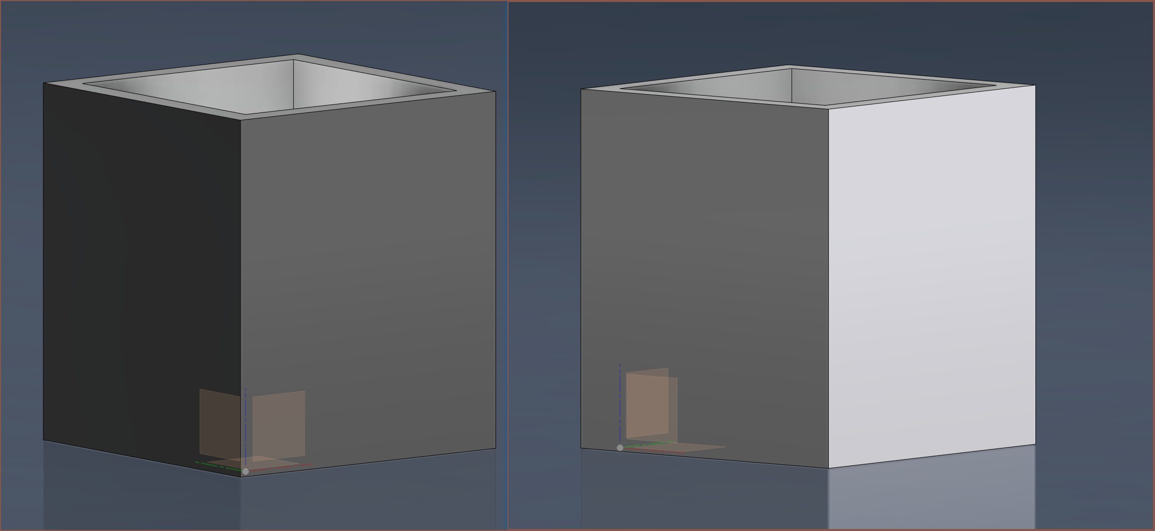
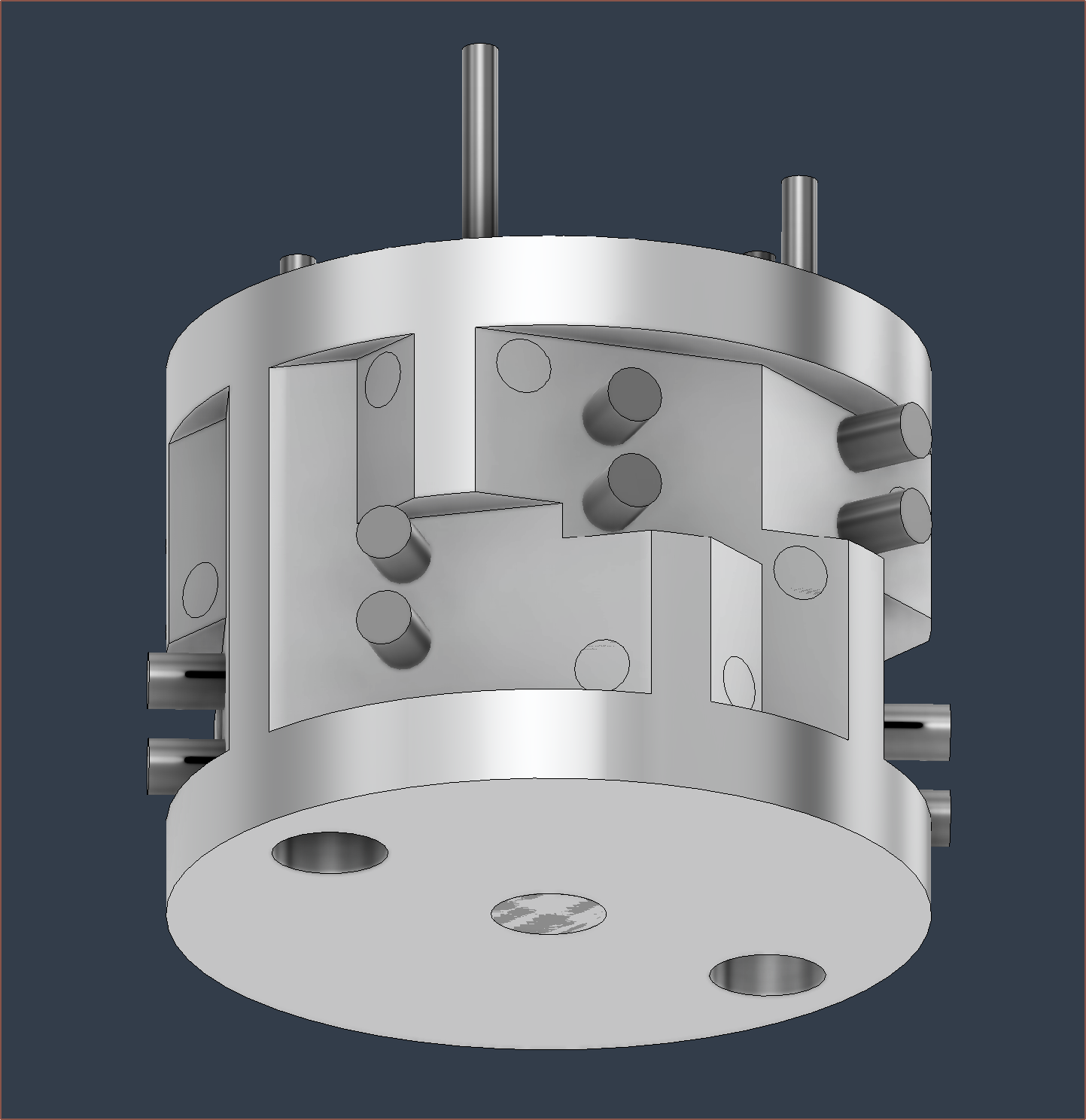
I've had this idea to remove some material from the front, allowing the CNC to use a much larger end mill for planing the faces.
-
[E1][M] 8 in 1 out hotend
10/05/2023 at 07:23 • 0 commentsOr 9 in 1 out if the centre is used.
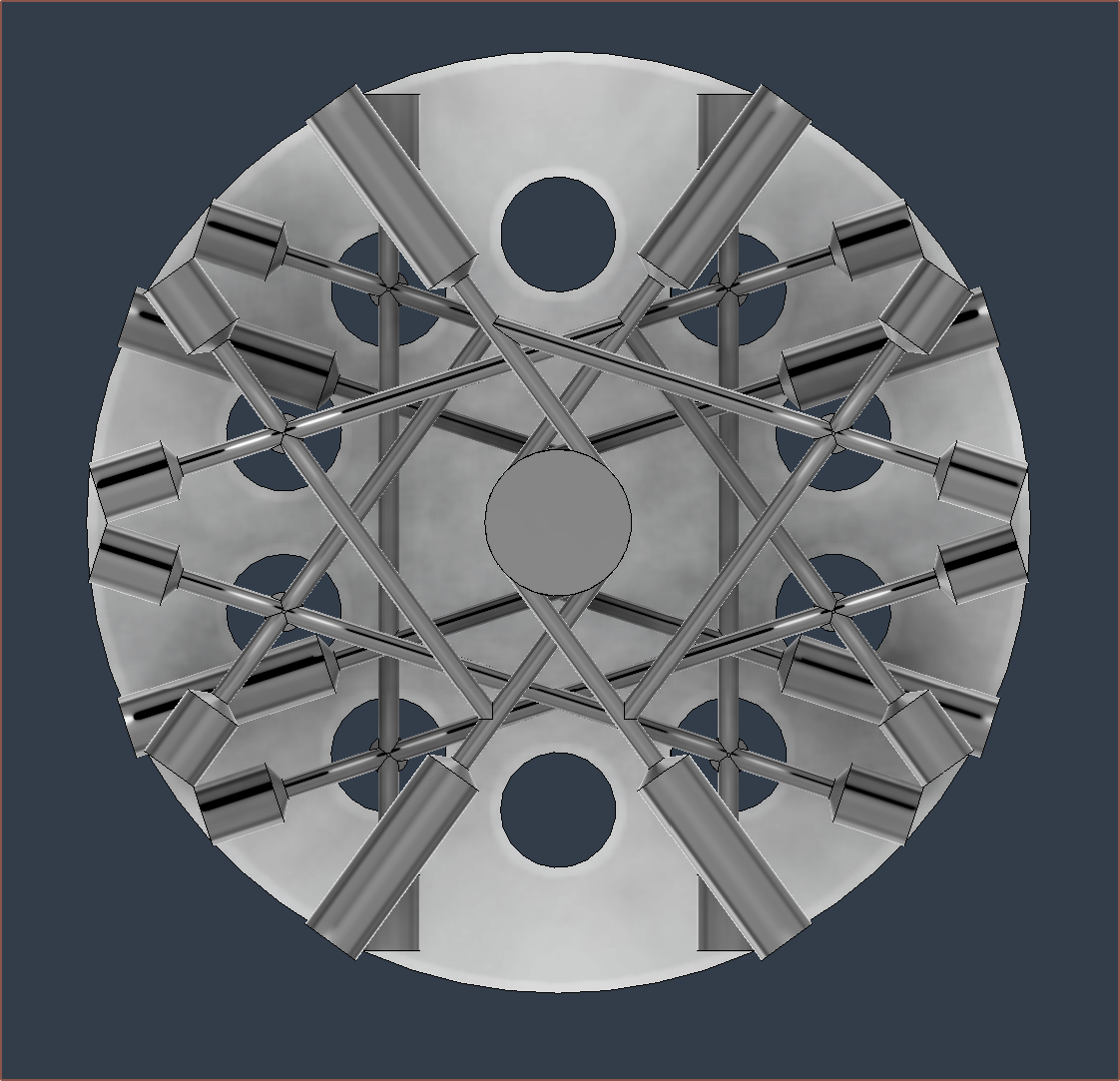
I know it looks complicated, but it's not complicated.
Modelling
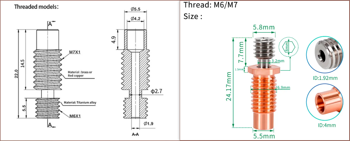
So, as I've read other engineers do, I wanted to see how far I could push the concept. The Palette 3 Pro had more inputs than the Palette 2 and Nozzleboss' 3rd version hotend had 1 more input than the 2nd, so it should be a natural progression to try for more inputs in the next prototype. Wanting to at least get to parity with the 6 in 1 out hotend from deckingman, I started trying to solve for that. First, I found some relatively affordable heatbreaks, chosen because they have a hex-nut geometry that I can use to tighten them and prevent leaks.
Then I spent some hours on the redesign:
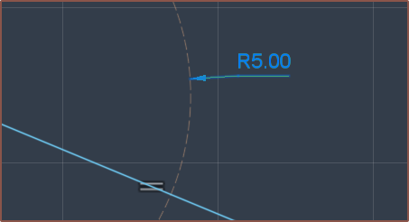
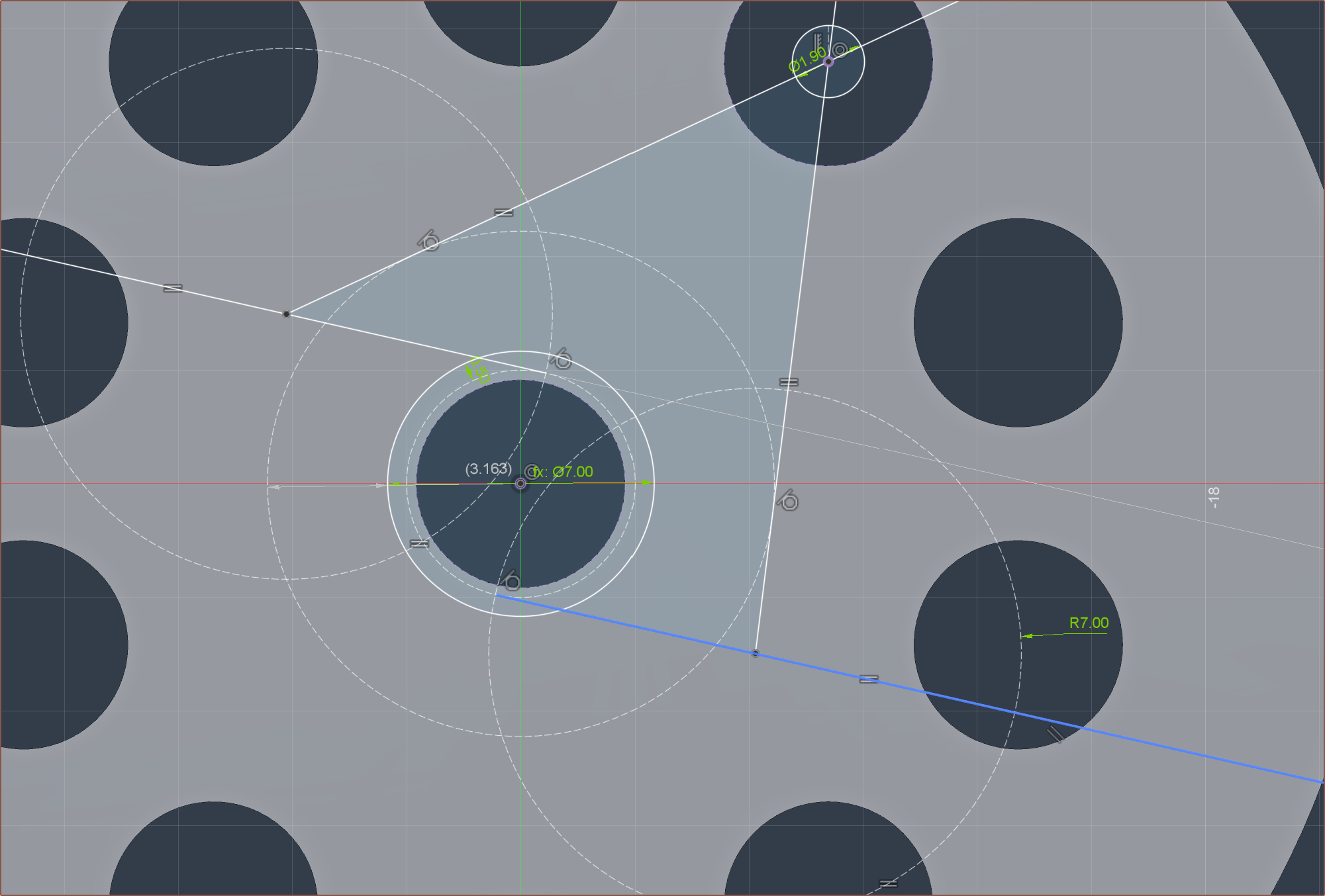
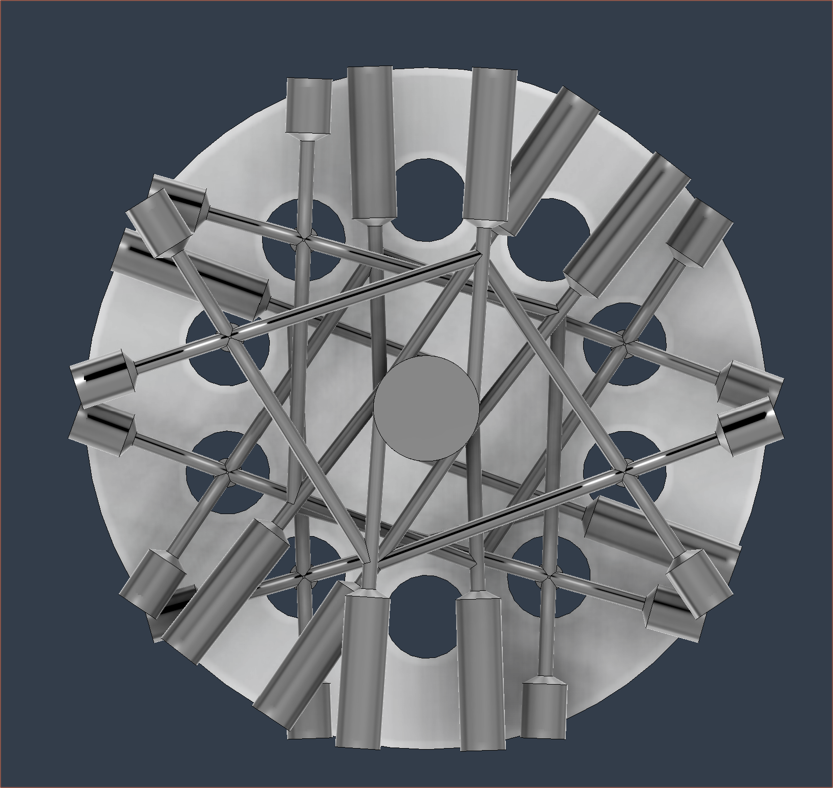
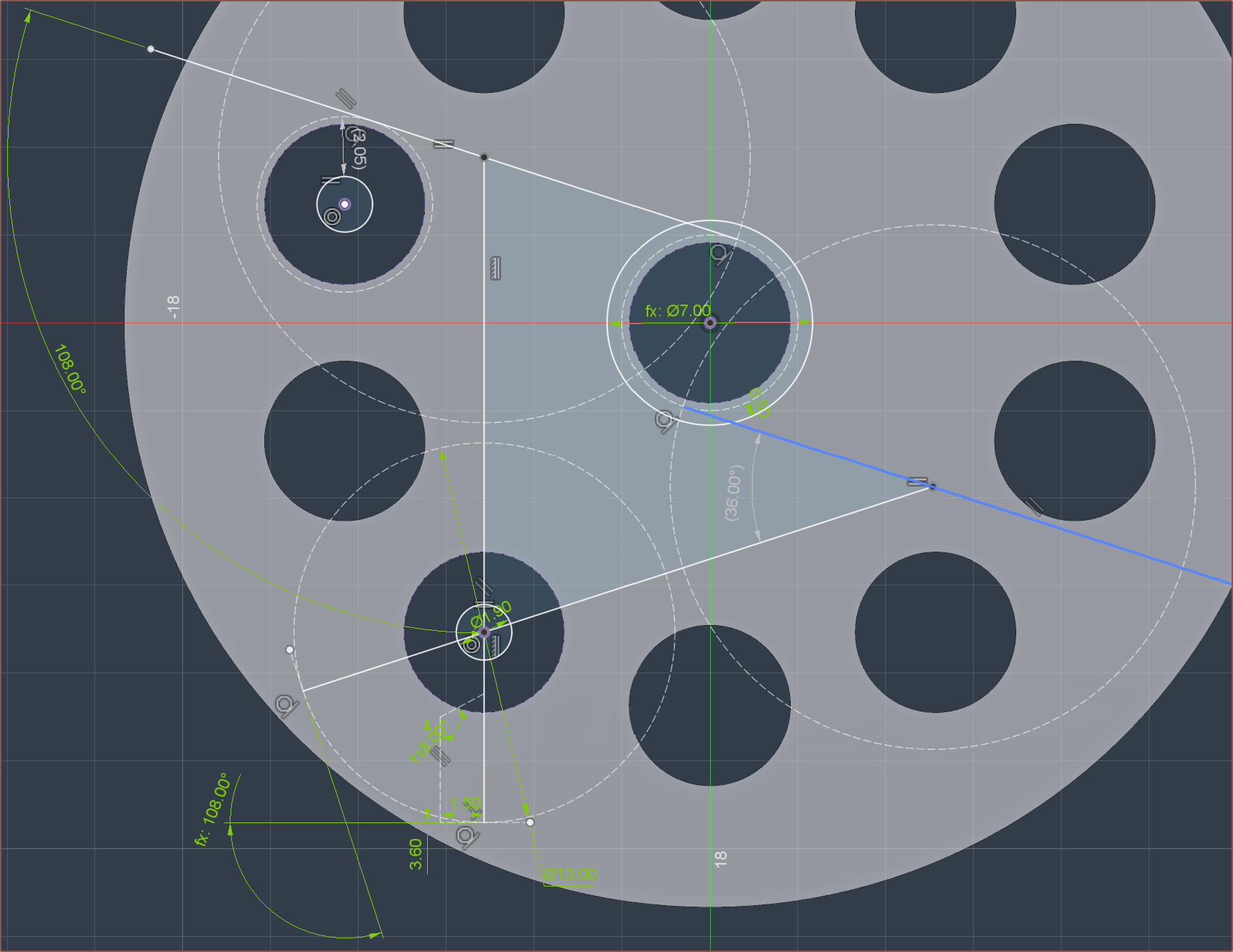
I think this took me 8 permutations to get. It was ok, but none of the drill paths lined up and I was wondering if the optimum solution is a power-of-2 kind of thing. It's only when I started trying to solve for 8 that I realised there was a dimension I didn't know was there:
So there probably is a 6 input solution where both paths are the exact same length, defined similar to the below sketch:
This is one of the first permutations. Solving this problem visually is a lot more like the Polysphere game, where I'm just rotating the channels in different ways and configurations to find a solution.
Eventually I got something promising:
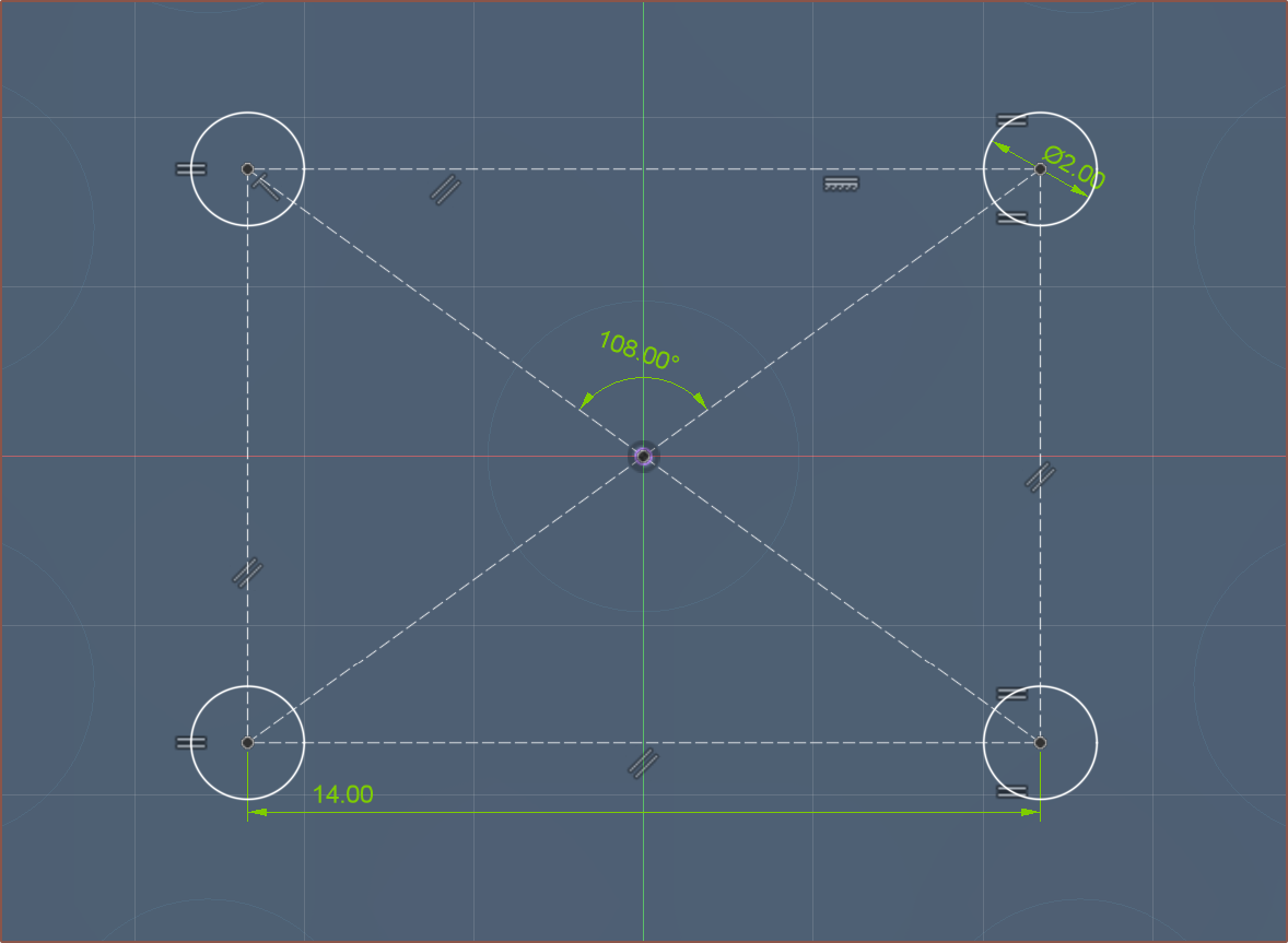
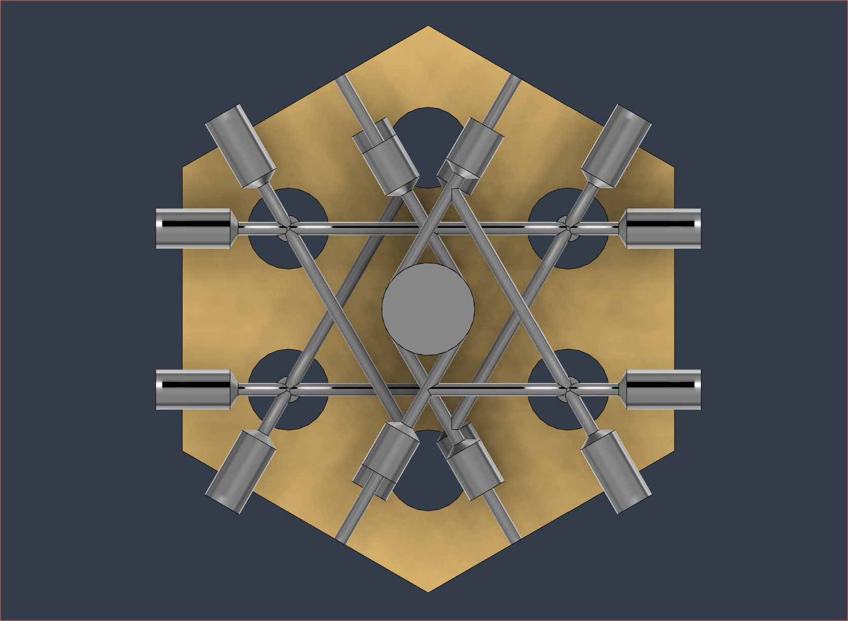
By making 2 angles 108 degrees (a multiple of 18, as 10 * 18 = 180) and having the paths be Standard (S). Mirrored (M), S, M, M, S, M, S, I got this:
Then it was a case of extruding the flats and push-pulling some faces:
The block is 30.4mm, but 30mm cartridges are rare. The only ones I could find were 40W anyway, so I just used 20mm cartridges and the hole is 20.1mm.
For the grub screws, I planned to use M4s since I can't remember having a single issue with them, unlike M3's. This requires an outer diameter of 42mm.
Also notice the fillets on the side. This is so that the endmill bit can reach everywhere, and I assume that the larger the fillet, the larger an endmill can be used and thus the faster the faces get milled.
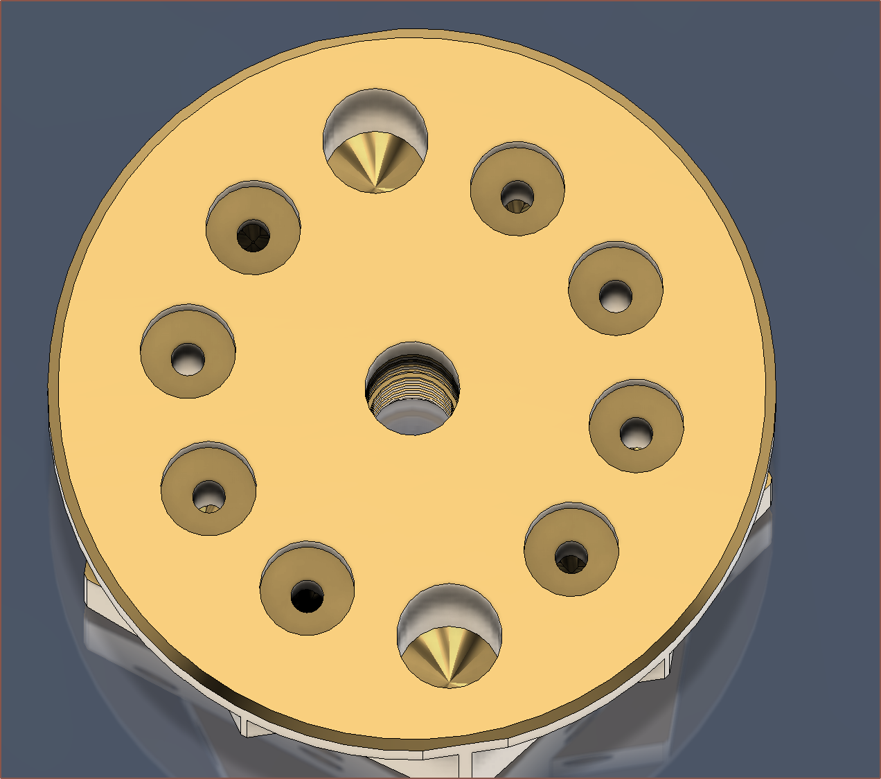
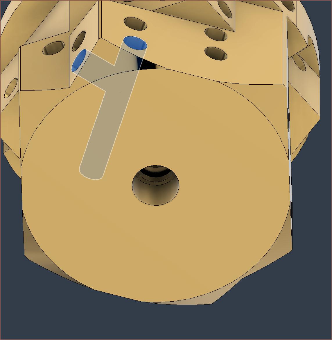
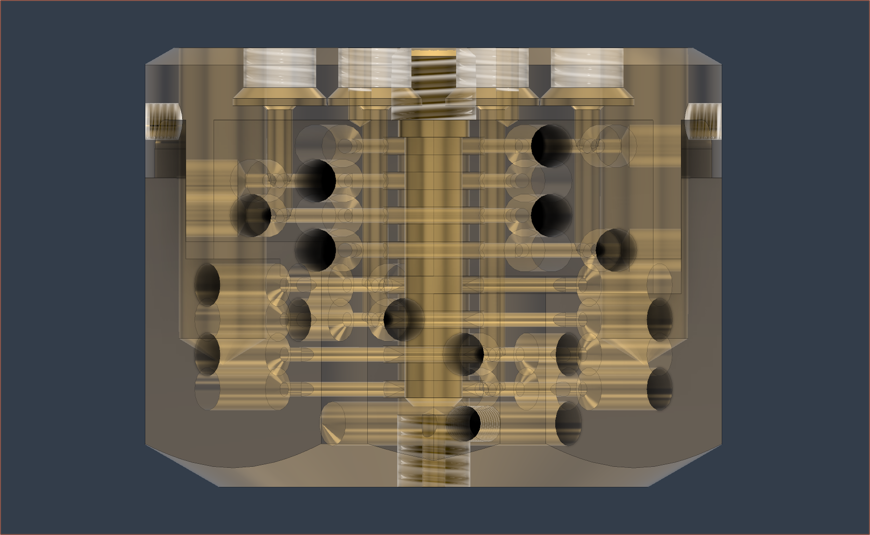
This is the holes for the thermistor and grub. Partially to reduce the amount of molten filament inside the heatblock and partially to increase the minimum wall thickness between the vertical paths and the plug holes, the vertical paths are now 1.8mm.
Next are the M2s.
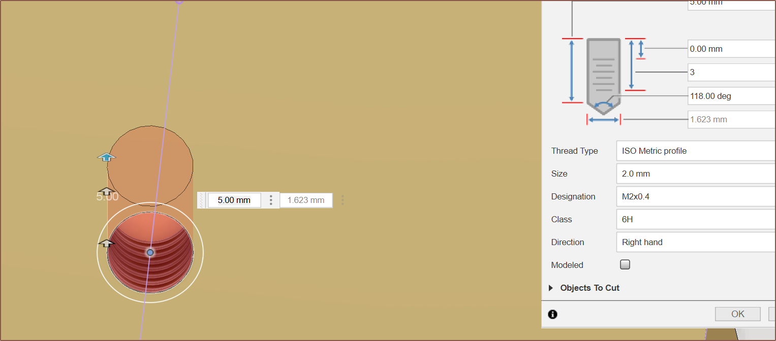
Pattern for the top mounting M2 bolts. They're 14mm across to match with the additional block's M2's on the bottom side. I found out that the Hole tool is very well featured and even allows me to set a specific depth for the threads.
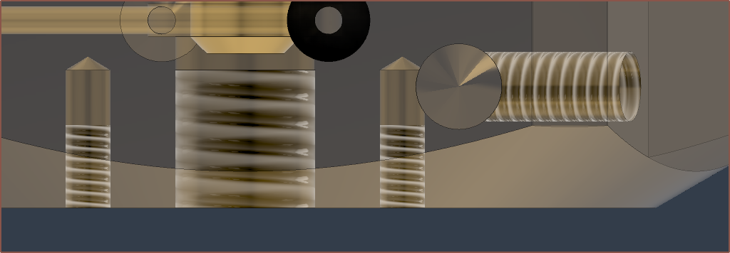
It slightly intersects with the thermistor hole, but I'm only planning to screw into a max depth of 3mm so it should be fine.
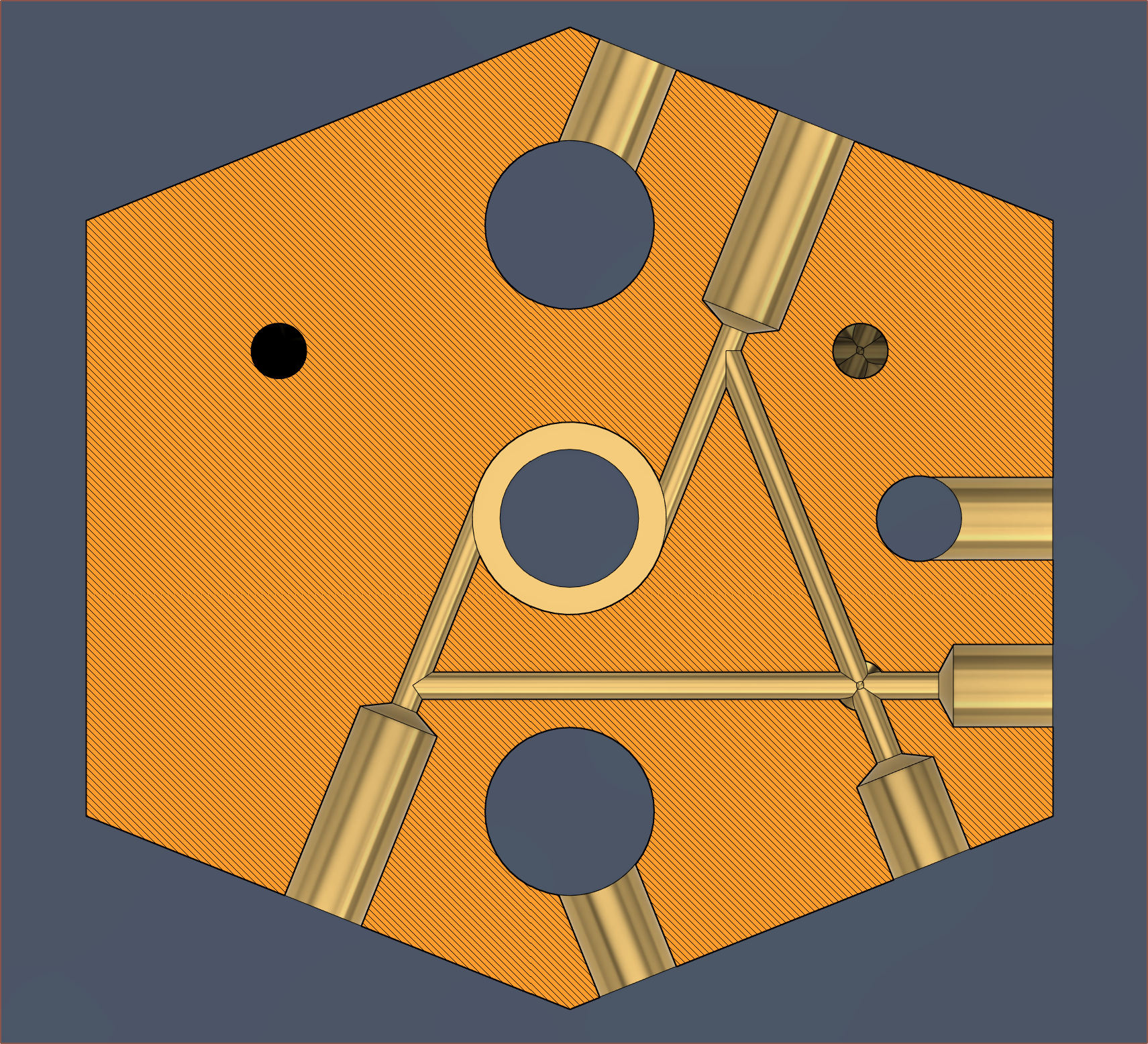
Transparent view of current design The main target mass of this 8+1 in heat block was less than 2X of the 4+1 in, which equates to 280g. An additional target was 250g. The design has surpassed both targets with a mass of 240g.
Next Steps
With 8 inputs, the situation with inactive inputs is now even more of a concern. The strategy of a lower combination temperature and separate print temperature is likely one of the better ones, though ideally there'd be some way of blocking off unused inputs.
I'm most likely going to have to design another part that looks like this but for M6:
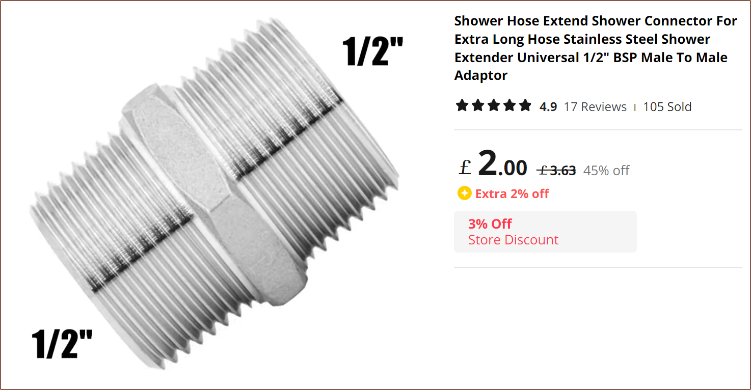
Alternatively, I could swap out the bottom M6 for an M7 so that I can use this part and just lathe down the copper side:
(A 3rd option could be doing the same as the 2nd but also reducing the M7x1 to M6x1)
Edit 1
I did some research on ball plugs, which can work up to 200C, but I'd have to integrate it somewhere where the filament is already molten.
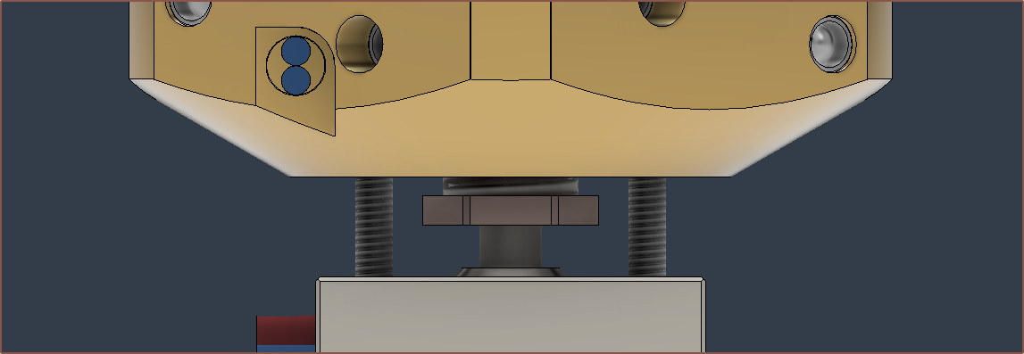
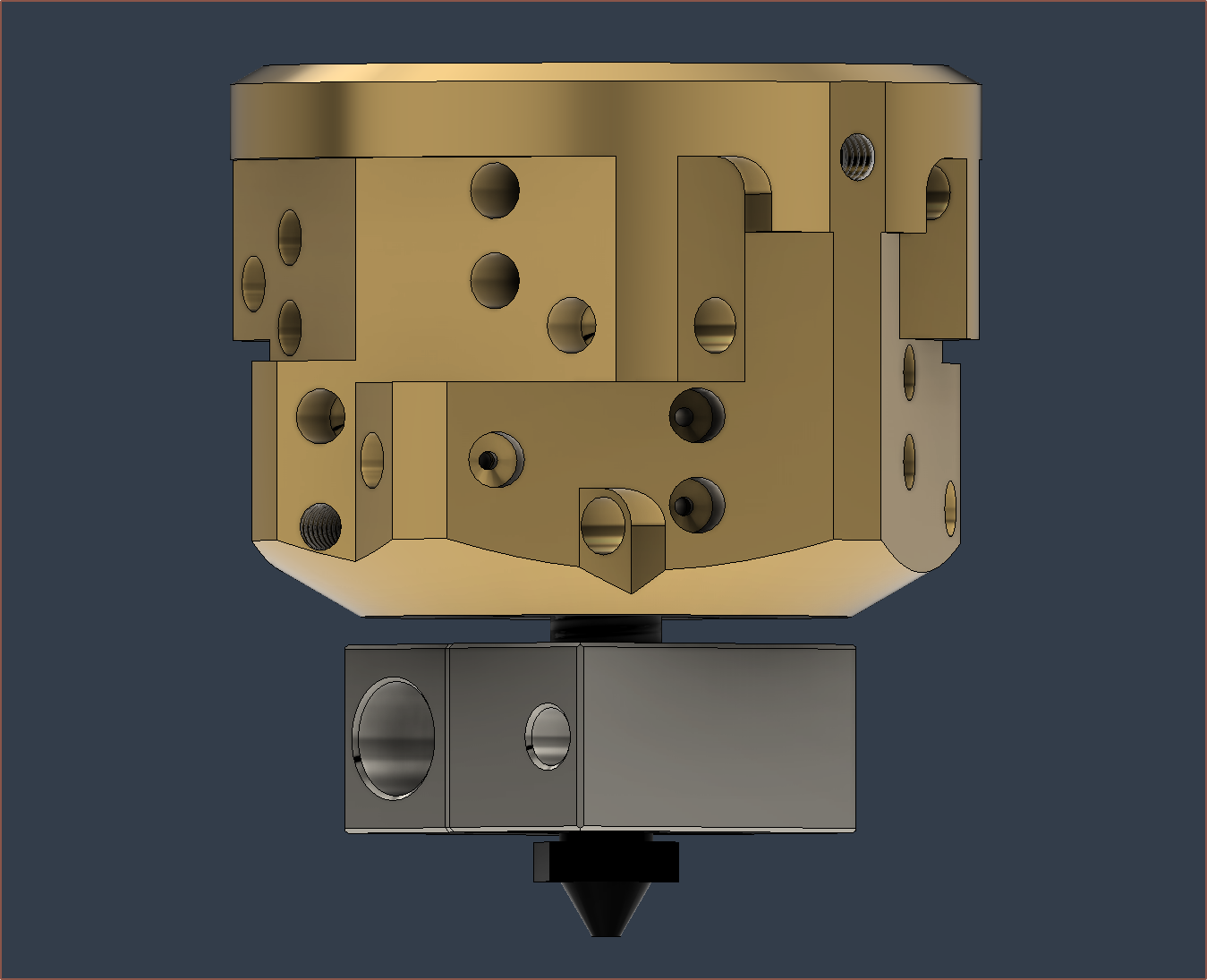
I've moved the thermistor, reduced the bite of the nozzle down to 4mm, increased the chamfer height to 4mm and rotated the additional block 180 degrees (so that the thermistor wires can be bundled together).
Hopefully, with a 2mm gap and the pitch of M6 being 1mm (thus, a 360 degree rotation translates the block up by 1mm), I should have enough adjustment space to get the additional block lined up to the M2 bolts, and a 1mm air gap between the two blocks.
-
[T][R] Dual heater zones?
10/01/2023 at 20:10 • 0 commentsSo I've addressed the potential of
- insufficient cold-end cooling by just using a 6028 blower instead of a traditional 4010 axial fan
- material leaks during printing by using expanding ball plugs and an undercut to the M6 heatbreak threads
- uneven coating by using a centrifugal inlet design
and now I'm wondering what to do in the expectedly likely situation where one or more materials just aren't used for extended periods of time.
As Deckingman, an FFF hobbyist that's been at this multi-material problem for longer than I have, pointed out (somewhere on the internet but I forget where), no amount of cold-end cooling is going to prevent heat from simply conducting up the material itself. Another thing he mentioned that I didn't know about is that PLA hydolyzes. Not exactly sure what that is, but research suggests that it's a kind of degradation of the material, which isn't good for business.
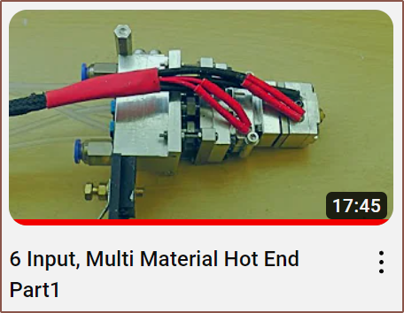
His flagship hotend is a 6-in 1-out multi-material hotend:
It looks massive and complex, but it can be split into 3 distinct sections: water-cooled cold end, combining block and heating block. Essentially, it sounds like the combining block is the only difference (in theory) from his design and a water cooled hotend:
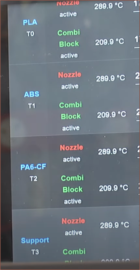
It sounds like all the tested materials (such as CF Nylon, TPU and ABS) can get through the combination chamber whilst it's hovering around 210C (see image below). This allows PTFE lined heatbreaks to still be used. My only concern is with PBT, which has a higher Tg and lower print temperature than most.
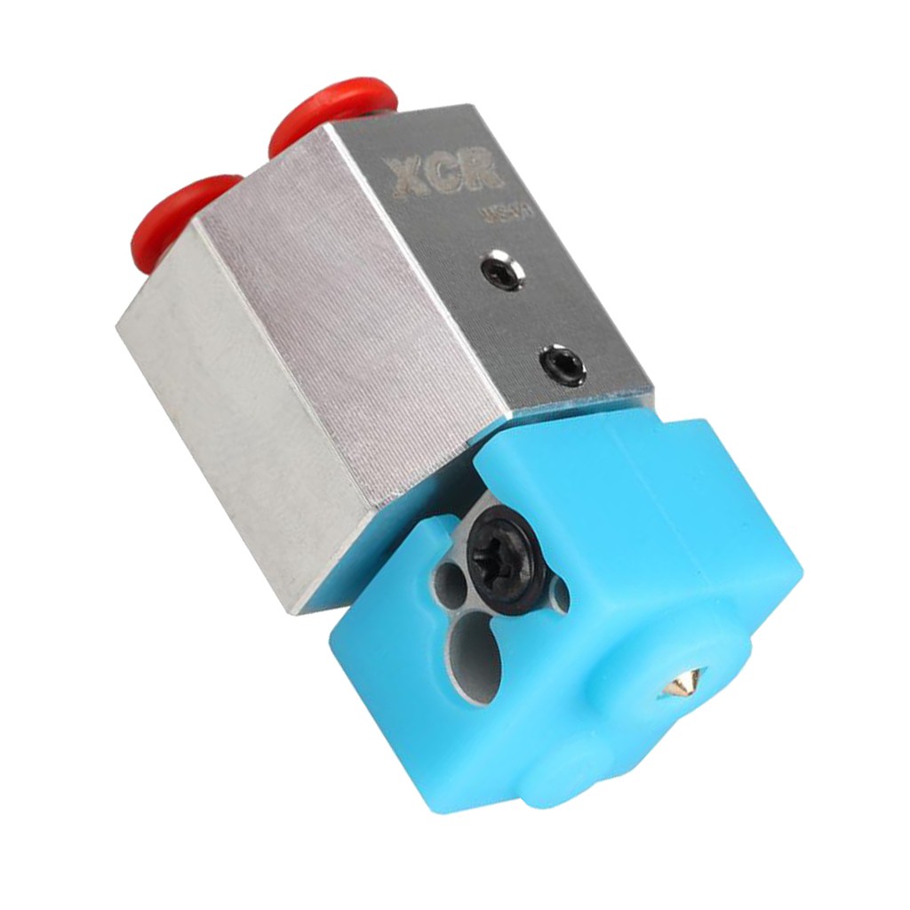
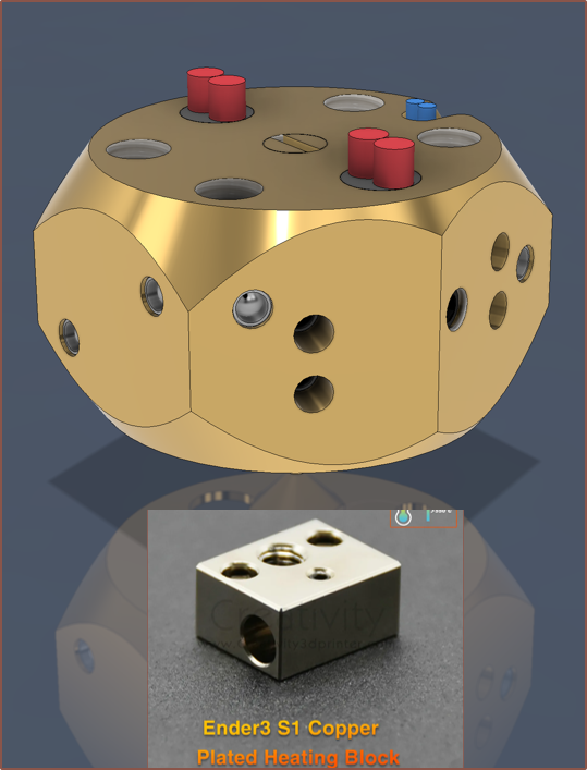
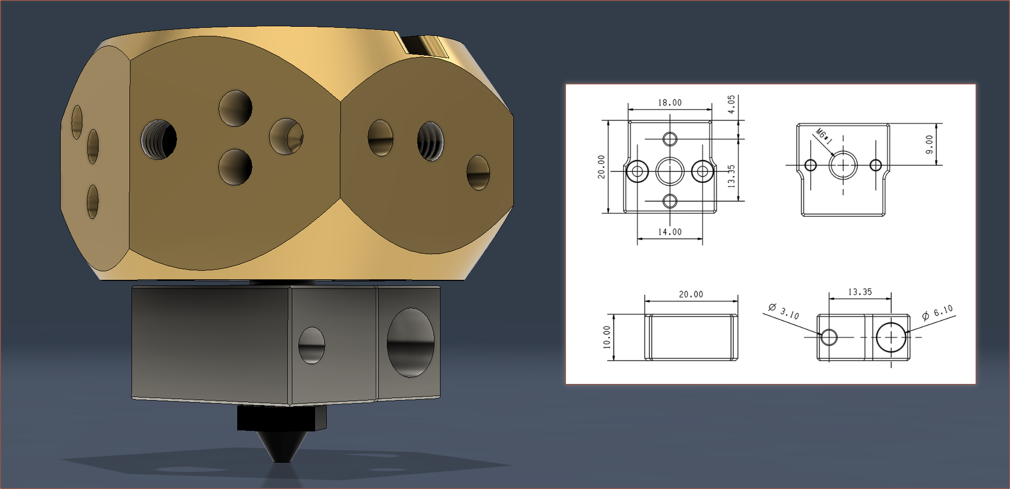
For the coaxial heatblock, it sounds like all I do is take a standard brass or copper heater block (that supports 1 handed nozzle changes) and I put it where the exit of the coaxial heatblock is:
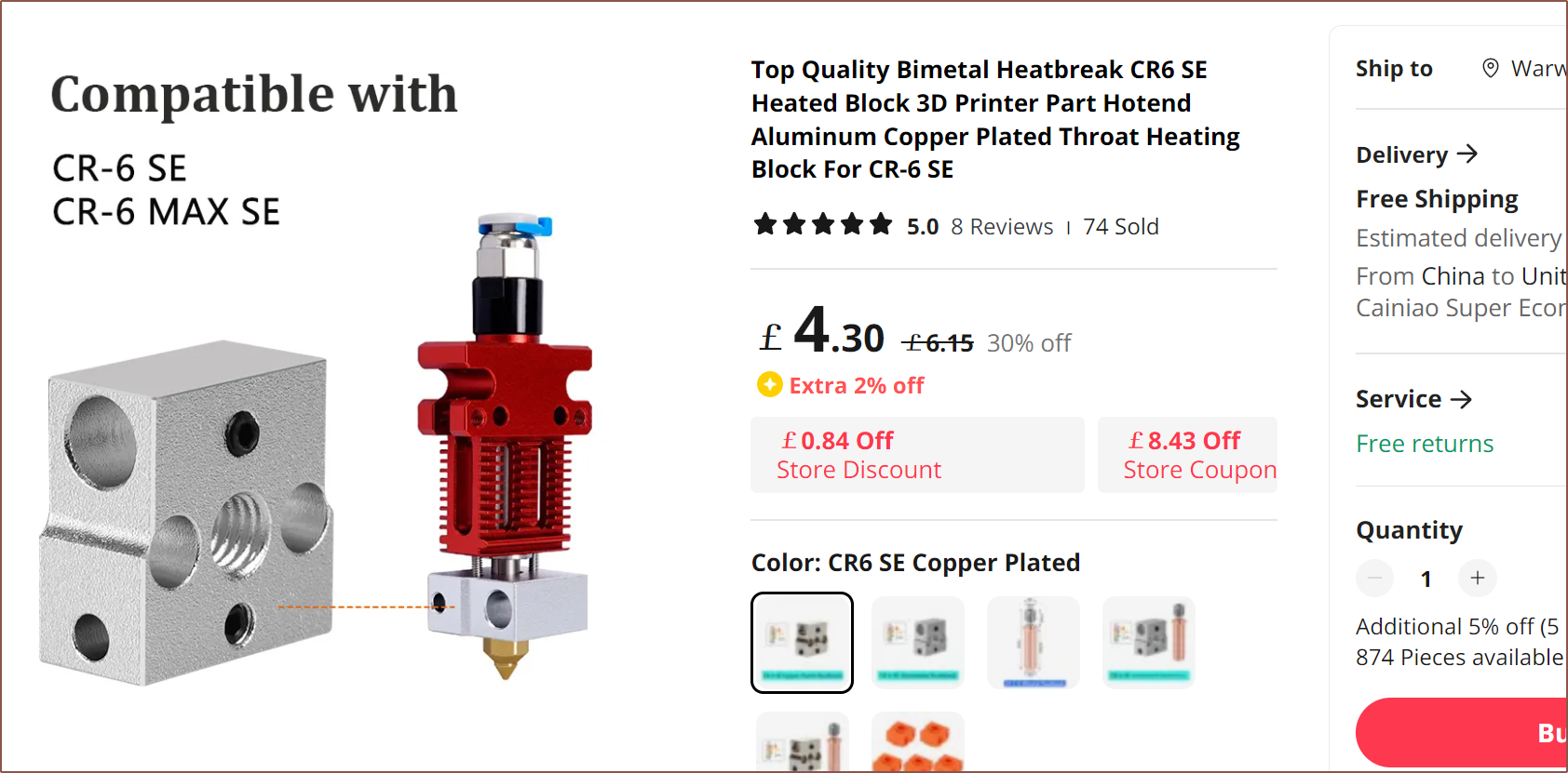
They're like £5 on AliExpress. I would've liked to see a block with a cartridge thermistor but ATM I can't find one.
Scrolls down to bottom of the very next page
Hey hey hey!
Now, what I wasn't expecting is how much hotend advancement has happened while I was preoccupied with all my other projects.
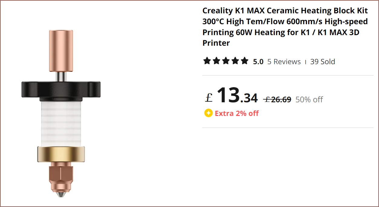
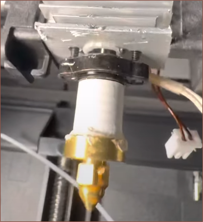
There's now a hotend that's like the Trianglelab ceramic one, but it has 2 screws to bolt into the heatsink to facilitate 1-handed nozzle changes:
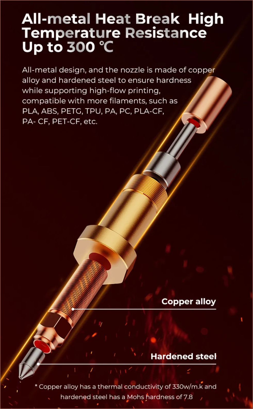
Source There are now copper nozzles with hardened steel inserts:
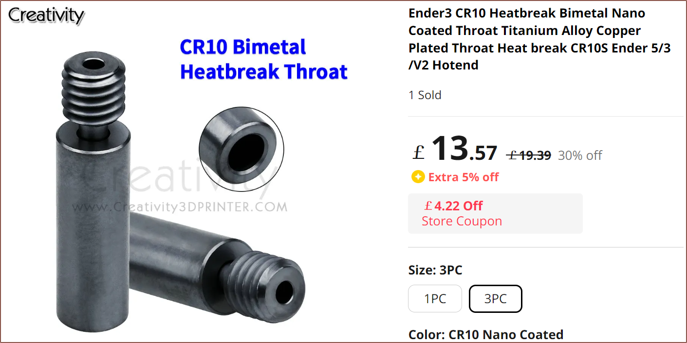
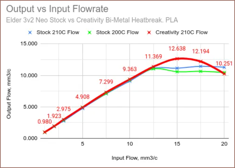
There are now nano-coated heatbreaks, which may be useful to prevent clogs:
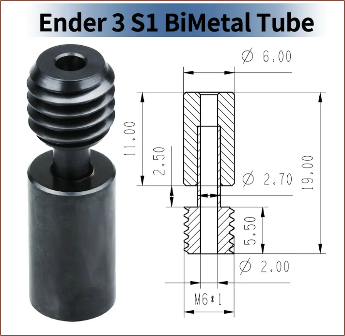
This is from an anonymous reviewer on AliExpress For the connection between the coaxial hotend and the additional hotend, a possible strategy could be to take the Ender3 S1 heatbreak, fillet 2 sides for a wrench and add M6 threads to it.
Alternatively, a volcano nozzle is used instead and any heat block short enough to fit inbetween the end of the nozzle and the bottom of the coaxial heatblock is used. A hardened steel nozzle should probably be used as it'll conduct heat less. The block would have to be 10mm or thinner, considering that the CR-6 SE block only has 0.5mm a side of space!
The brass heatblock is 143g and the copper heatblock is 24g.
-
[M] Centrifugal-inlet design with expanding ball plugs
09/30/2023 at 20:25 • 0 commentsA section view of the populated design. I'm calling it "centrifugal inlet because it looks like a centrifugal fan. So, understandably, the technician isn't going to spend another 24 straight hours making another heatblock prototype, especially with first years now showing up to university. He believes that an assembly line could probably make them by the 100s, but creating a one-off is tough. He did note that the small side threads were the toughest part of the design to manufacture. He also warned that the surface finish needs to be sufficiently good to create a seal with a ball bearing, which is the kind of thing that E3D likely has ommitted from their drawings (or I just never saw them because the drawing was hard enough to read already). Lastly, all the technicians and I had a short brainstorming session of what can be done to seal the drill bit entrance holes.
Thus, in gearing up for a round 2 with PCBWay, I wanted to see if I could do more than the solution I thought up a few days ago.
For starters, I found a post on the reprap forum where someone created a silver heatblock and observed that it got to temperature in 1/4th the time. Looking up the specific heat capacities of metals, Aluminium is 921 units and silver is 238. Brass is 402 units so I've gone back to that.
Then I was trying a few different search terms and stumbled on this:
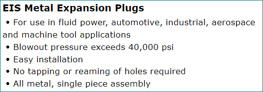
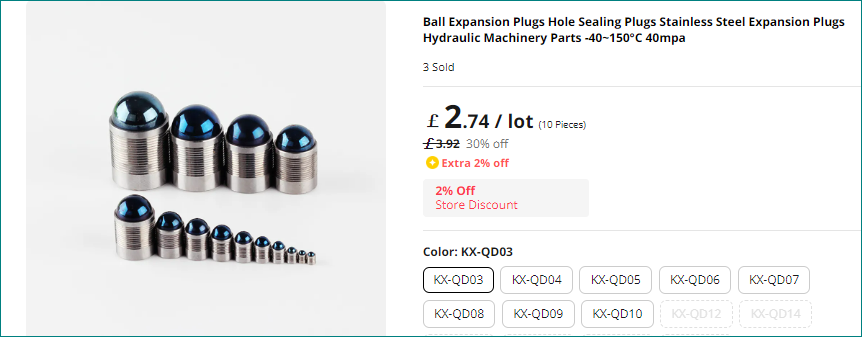
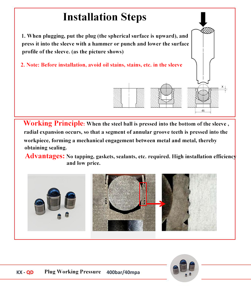
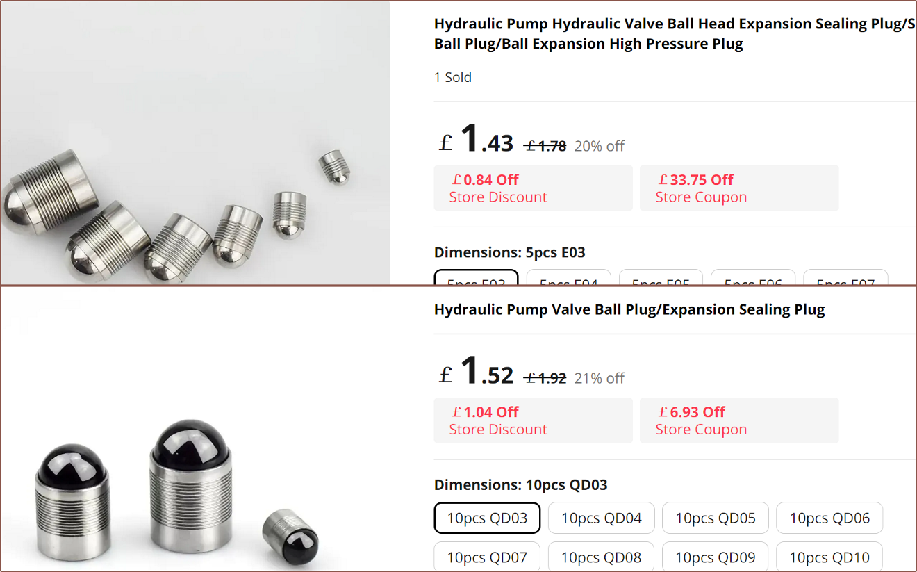
Me In The Past: Whaaaaa!! Tapless?! It turns out that there's a new invention between when E3D made their Cyclops in 2014 and now. And the best part is that I found it on AliExpress:
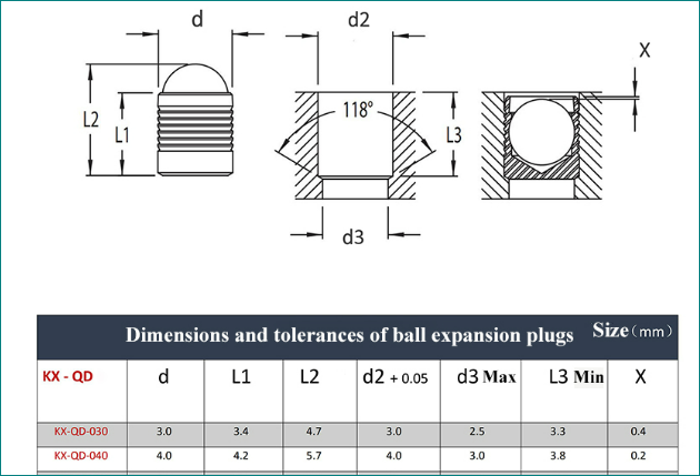
Me In The Past: Uwahhh if I use these, my heatblock is going to look so advanced and futuristic. As you can see, they use the standard 118 degree taper that common drill bits create.
This image here shows how the thing actually works. When I first saw it, I was under the impression that the ball would be doing the sealing and that it's just a combined ball bearing + grub screw. This is when I sat back in my chair, breathed out and uttered "It's a solved problem...". That was, until I realised that it listed that the max working temperature was 150C. I'm don't know why, but I can only guess it's something like the material or perhaps trapped air? I did some searching and some manufacturers protect their sleeves with zinc, a material I hear doesn't work too well at FFF 3D printing tempteratures.
There were 2 other kinds that I found online. They didn't list any temperature range, but the top one is made with stainless steel for both the ball and the sleeve so it's probably OK to use.
After that came the trail and error process of trying to incorporate the off-centered inlet approach I talked about a few logs ago. I hypothesised it and if I'm going to be spending another $70 I should at least try and validate the hypothesis while I'm at it.
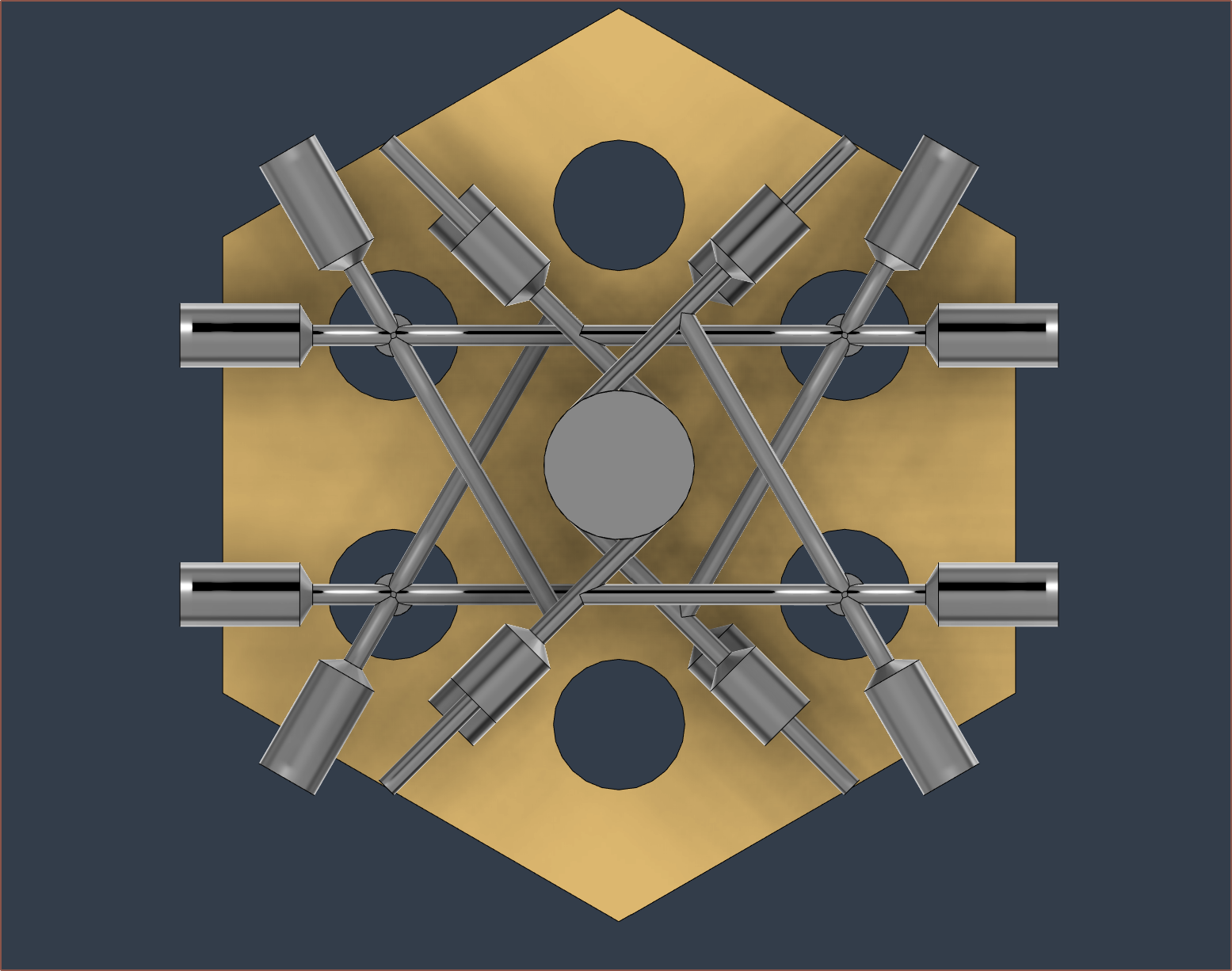
As you can see, there's not really any space for the heater cartridges. This one had another 4 angles that somehow needed to be accurately tapped. I decided that I should at least make the input order convenient. Thus, the bottom-most input is closest to the location where the CR10's / Ender3's default extruder would be. Coincidenly, that gave me this pattern which I saw as salvageable. instead of the 60 degree angle where the 2mm path splits into 2x 1mm paths being 60 degrees, I made one aligned with the input path. I changed the angle from 75 to 68 degrees and the internal groove inputs were almost aligned, so I went into the sketch and tweaked it to get Fusion360 to calculate the exact value. And there I had it: a solution. I'm expecting this squashed hexagon shape to be milled out of a larger, rectangular block. I'm also hoping that the slight length mismatch between the 1mm paths won't cause noticeable pressure imbalances. It's very slight -- only 3mm difference.
I'm expecting PCBWay to have more tooling, so I've shaped the threads to use the tools I discovered last log. Lastly, I do a 55 degree revolve chamfer instead of 45 degrees:
The heater cartridges are the same distance appart in both images. The dimensions of this new one and the one that was fabricated are rather similar. I'm wondering if I should fillet those sharp edges though. It's probably fine.
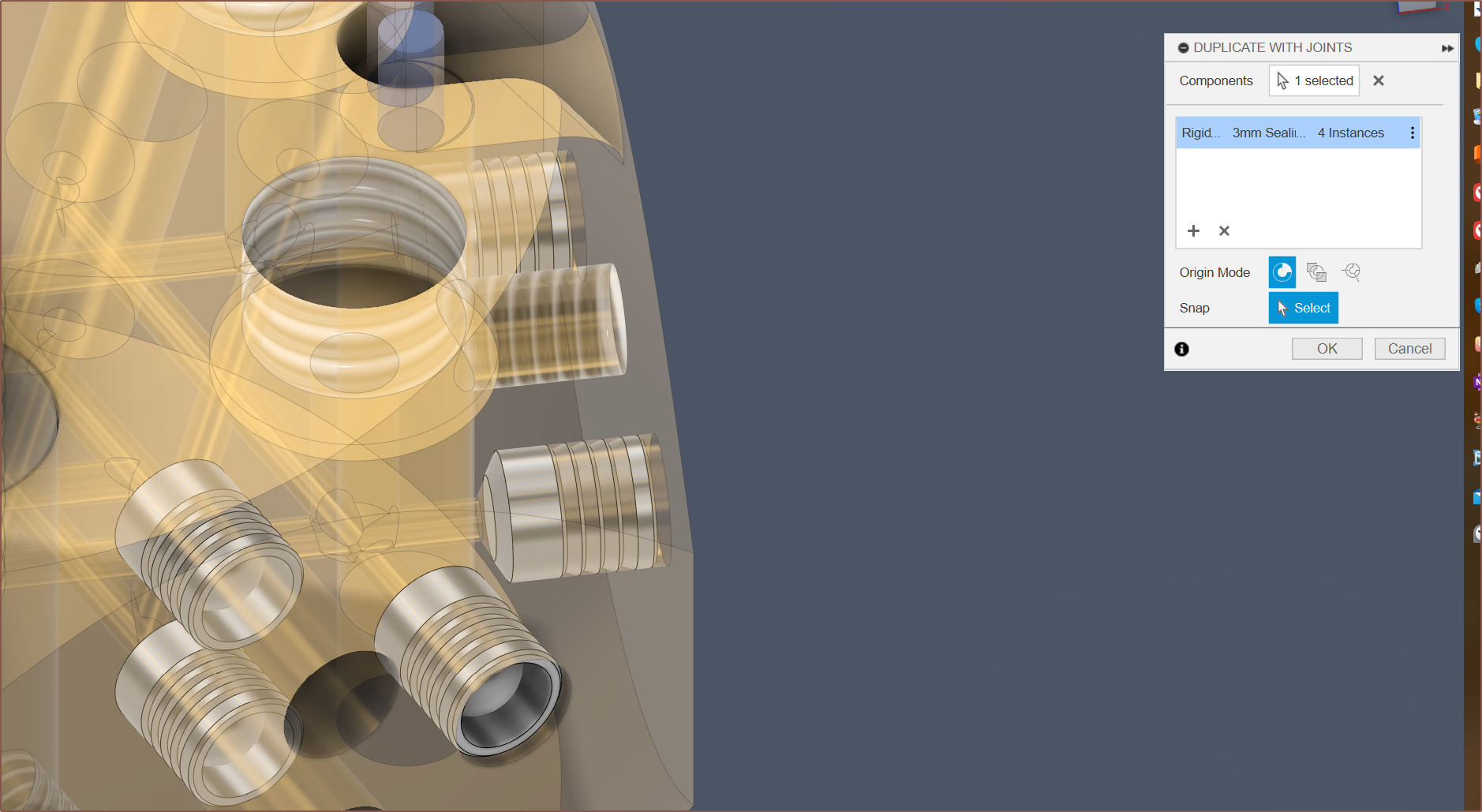
Next I found the most similar CAD model I could and modelled the ball inside the sleeve (as they all are modelled with the ball in the position as sold) and then tried the new Duplicate with Joints feature.
I'm probably going to have to back over it manually like what I did in the past since the tool doesn't use parameter values but just copy-pastes the absolute value of the joint. The feature also fills the timeline more than it needs to:
Anyway that's the new block and where I've got up to. Here is what the entire block looks like:
Now to see what PCBWay thinks of it.
-
[M][T] Internally groove the heatblock-heatbreak mating surface?
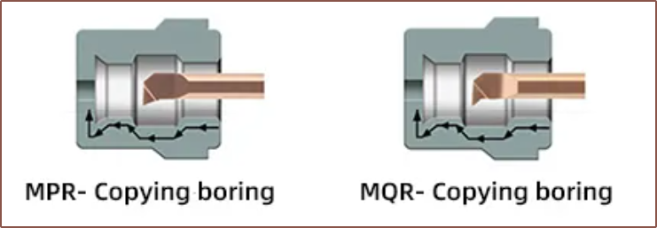
09/25/2023 at 21:09 • 0 commentsI have a diamond hotend I never got around to using and I looked at the M6 thread inserts to see what was done for that heatblock, and it looks like the bottom-most threads a missing. It actually looks like there's a very slight undercut. This is likely due to the inability to perfectly tap all the way to the bottom of the blind hole. I'm hypothesising that this is the reason why I got leaks.
To counteract this, I've added more internal groove cuts to the bottom of the threads. It's rounded because it uses the same tool as the coating grooves, though something like an MPR or MQR looks to be more of a match for this.
-
[M] Visible indication of full grub tightness
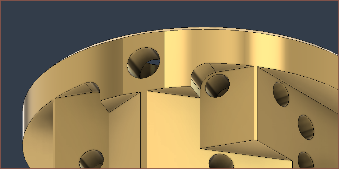
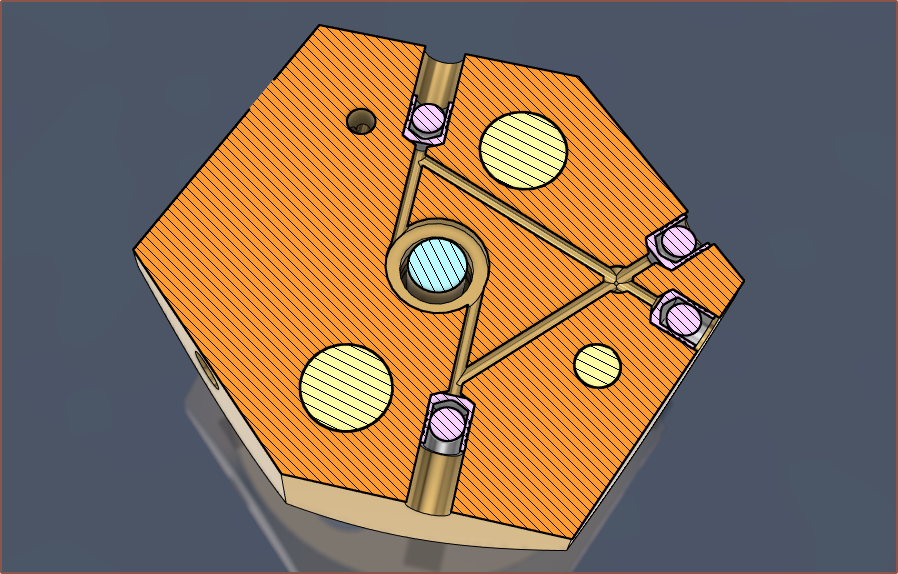
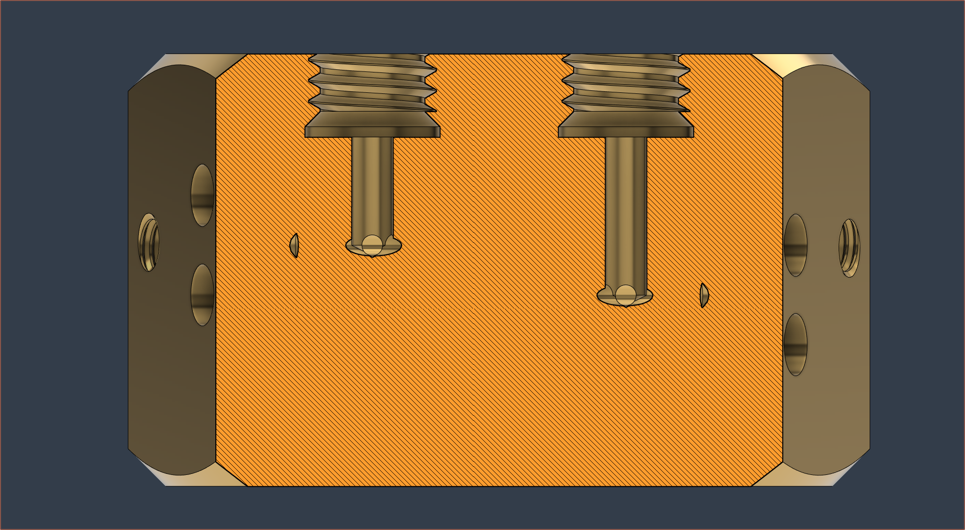
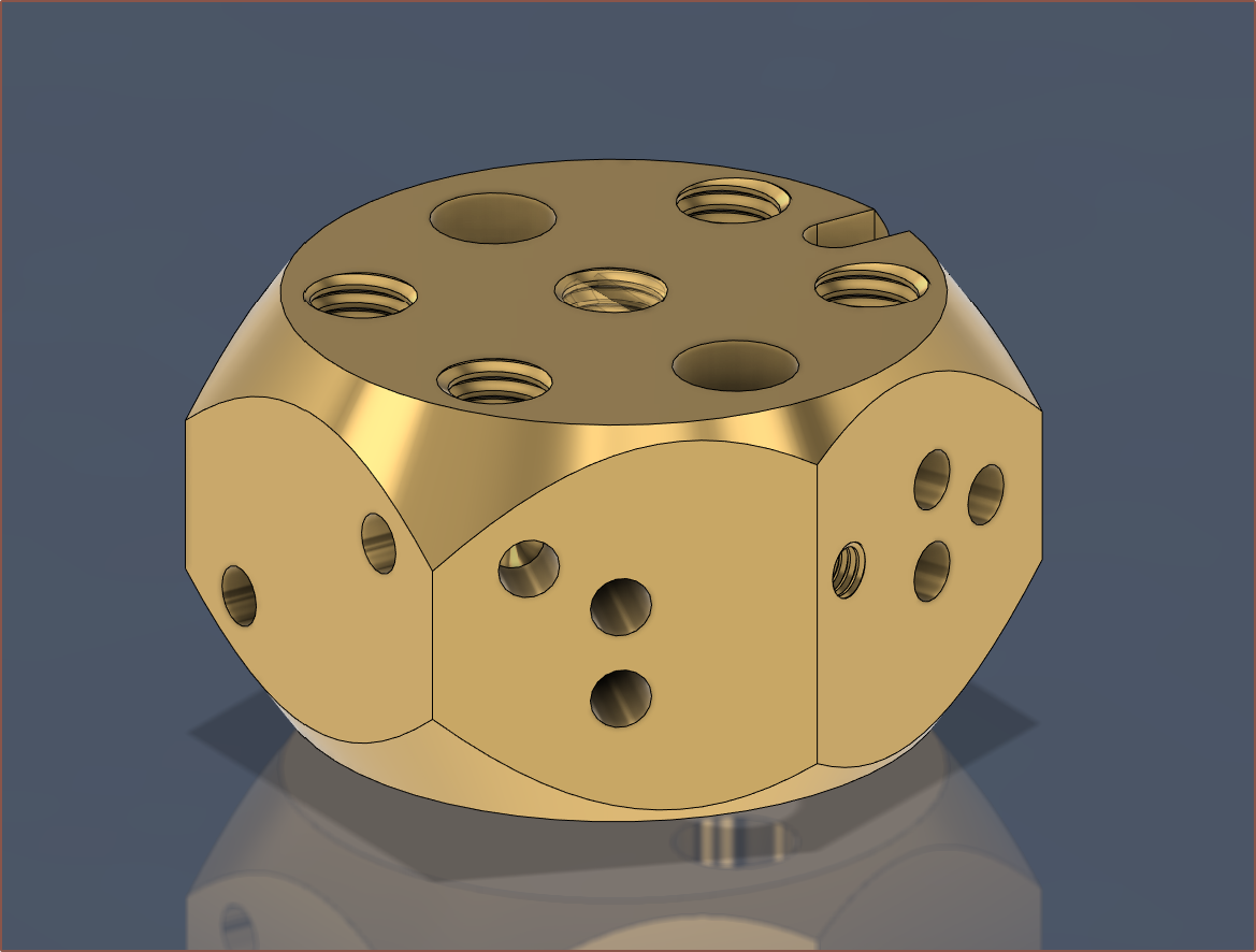
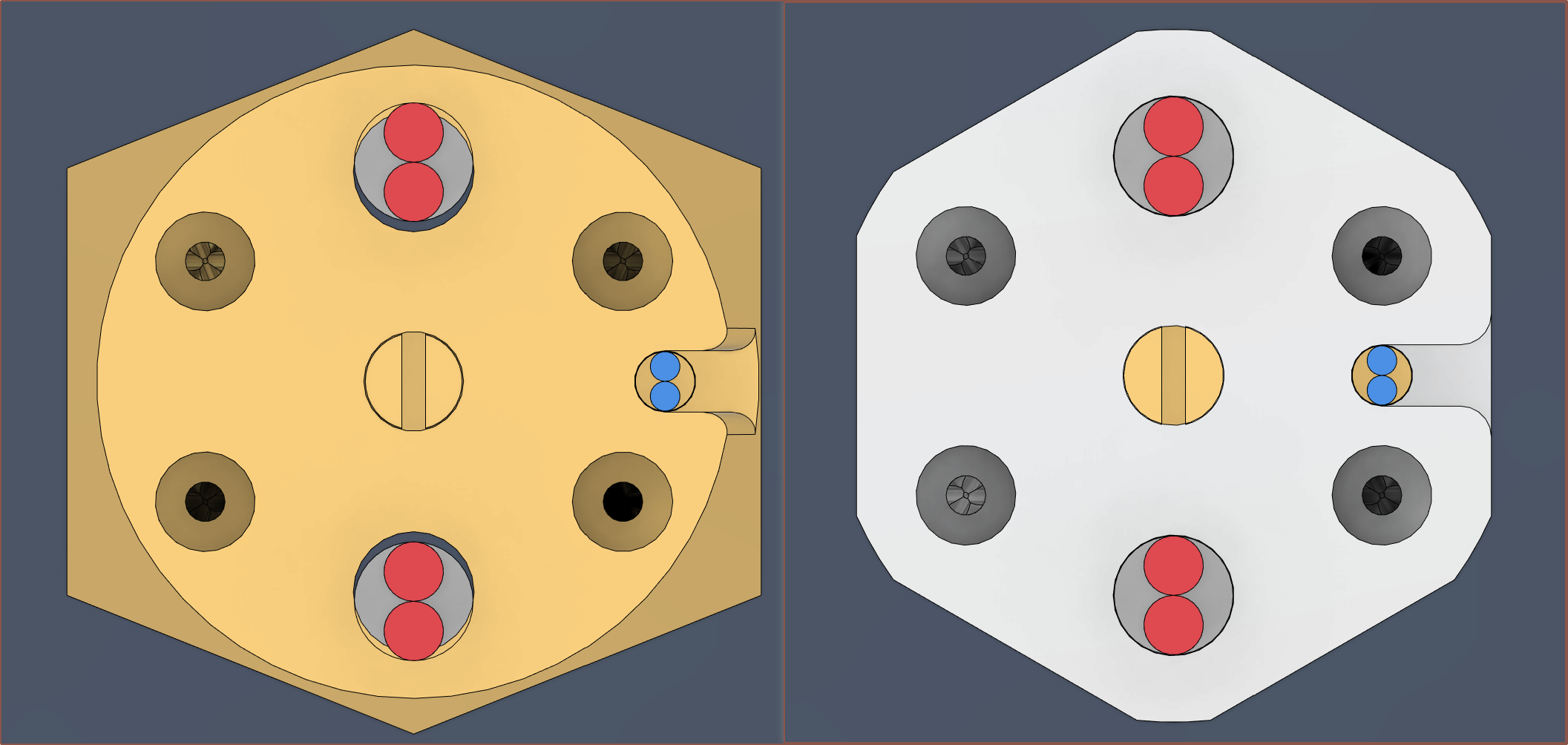
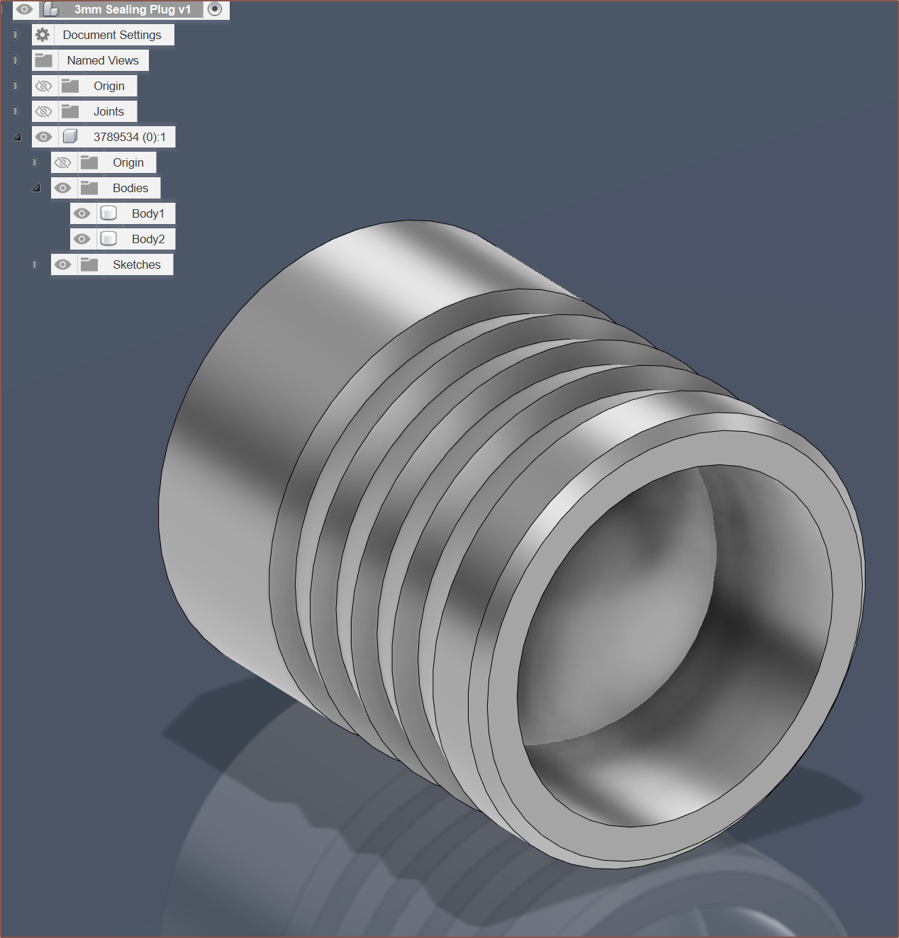
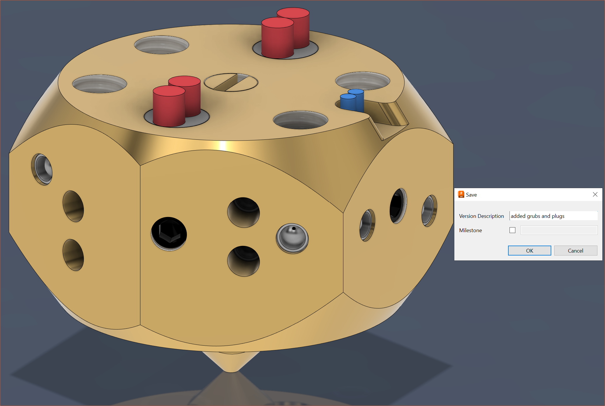
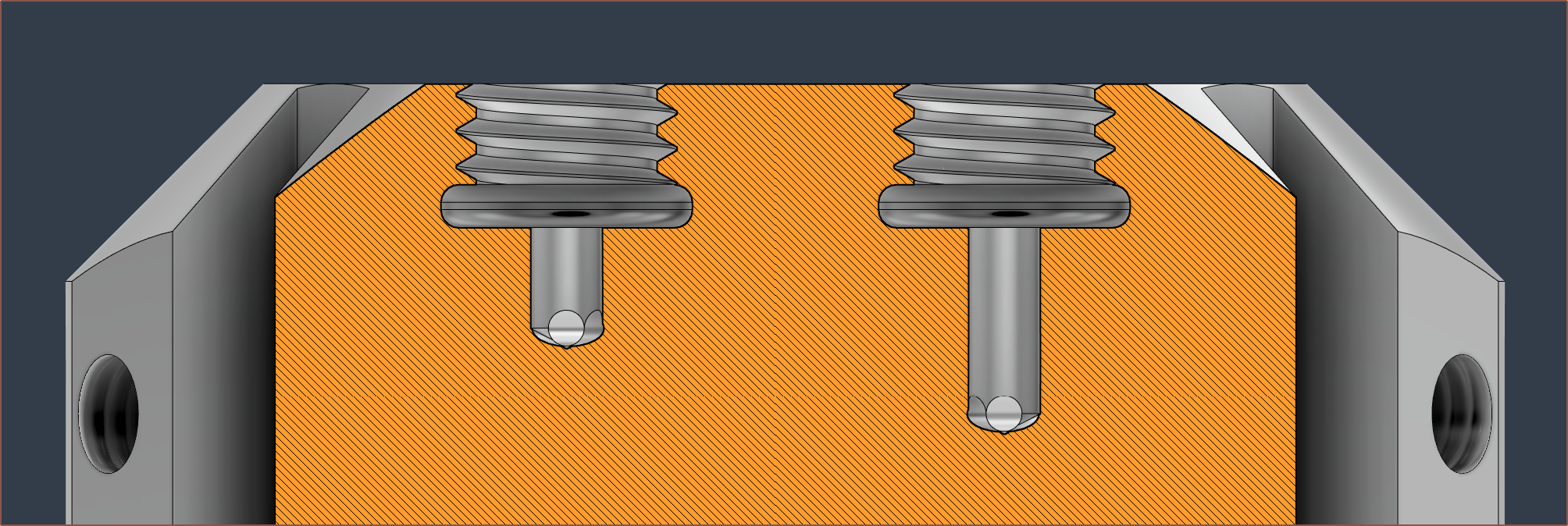
09/24/2023 at 22:21 • 0 commentsBack in May, the technician that fabricated the first prototype suggested that the grub screw length should be flush with the face so that it's more visibly obvious when the grub is fully tightened or not. Thus, I've added some 4mm trenches so that the actual length of the screw+ball bearing stoppers are the same everywhere.
I've also had to reduce the depth of the heatbreak threads to prevent the topmost grub void from creating holes in the mating face. I've ensured there's at least 1mm of wall thickness.
Using a 2mm ball, and a 4mm grub screw, the top of the screw should be just-about below the surface. It might be better to use a 2.5mm bearing to be even closer to the exact length.
-
[P] Outer Cover and leak detected
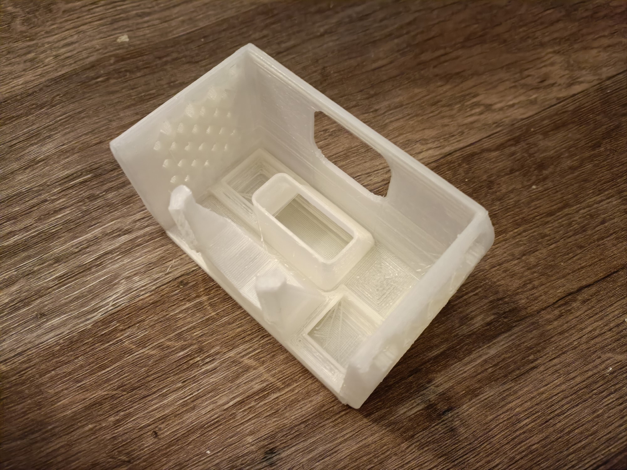
09/20/2023 at 18:02 • 0 commentsI've finally printed out the outer cover to see if there's any obvious issues, but more to make sure it's printable in the first place.
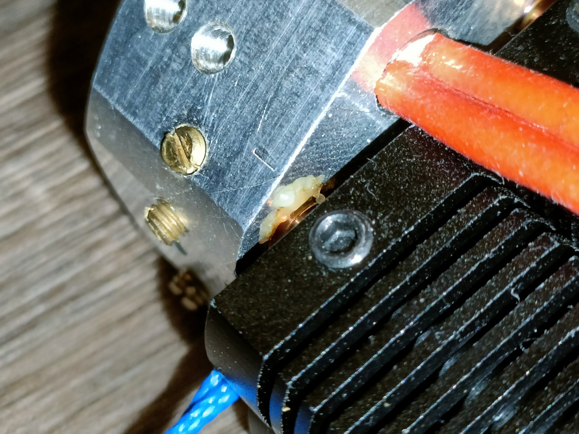
I've also looked a bit closer at the hotend and noticed that 2 of the 4 heatbreaks actually leaked a small amount of material. Considering I've only put in a small amount of material, I'm going to have to some cleaning and tightening. At the same time, I'm actually not sure on a suitable strategy for actually going about sealing that still allows the hotend to print at 250C without offgassing concerns.
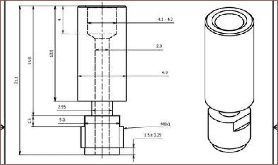
I think a good place to start is getting heatbreaks that can be tightened using a wrench. Unlike traditional hotends where the nozzle is tightened to provide the seal, the tightening has to come from the heatbrake with this kind of design. The E3D Cyclops seems to adopt 2 flattened parts of the thread to allow for this:
It's likely so that the torque of tightening the heatbreak doesn't risk shearing the thin heatbreak section. One of the issues I'm encountering in my mental simulations is that there's a lot of stuff around the heatbreaks (such as other heatbrakes or thermistor wires) that would seem to make a wrench-tightened solution difficult.
-
[T] Hotend hypotheticals: Off-centered inlet approach?
08/29/2023 at 14:09 • 0 commentsHeinz has recently uploaded a video showcasing version 3 of his design, which looks like this:
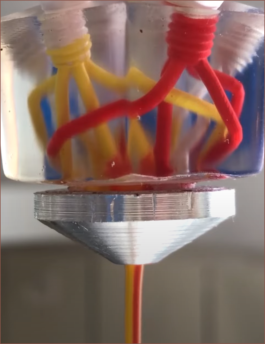
The main improvements is that it now has a third coating colour and that the material now comes around in 4 positions instead of 2 in an effort for even better coating. However, a notable snippet is this:
In the months I've been staring at my CR600S instead of fixing it and testing the coaxial hotend, I've been trying to hypothesise as to why this general hotend design could be a promising solution to colour mixing.
1] Mixing across a curved line instead of an infinitessimally small point
Part of the reason why I wanted to look into a machined hotend was to ensure the geometry of what I'll call the "cutting edge".
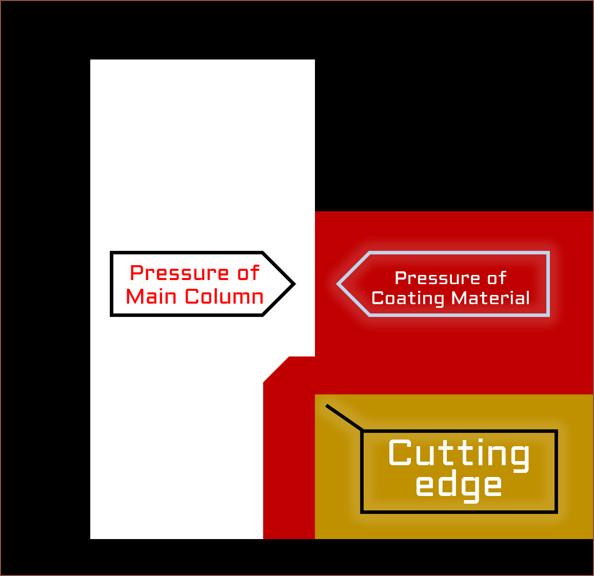
This image shows what I predict is happening at the point of this cutting edge. Similar to how a pencil sharpener cuts off a thin strip of wood, this edge would cut off any coating material where the pressure exceeds that of the main colum, slightly pushing it past the edge.
To coat a cylinder, the above diagram would be revolved by 360 degrees around the leftmost edge of the Main Column. Thus, the goal is to obtain a uniform pressure of the coating material around this 360 degrees.
2] The internal groove reduces the pressure difference
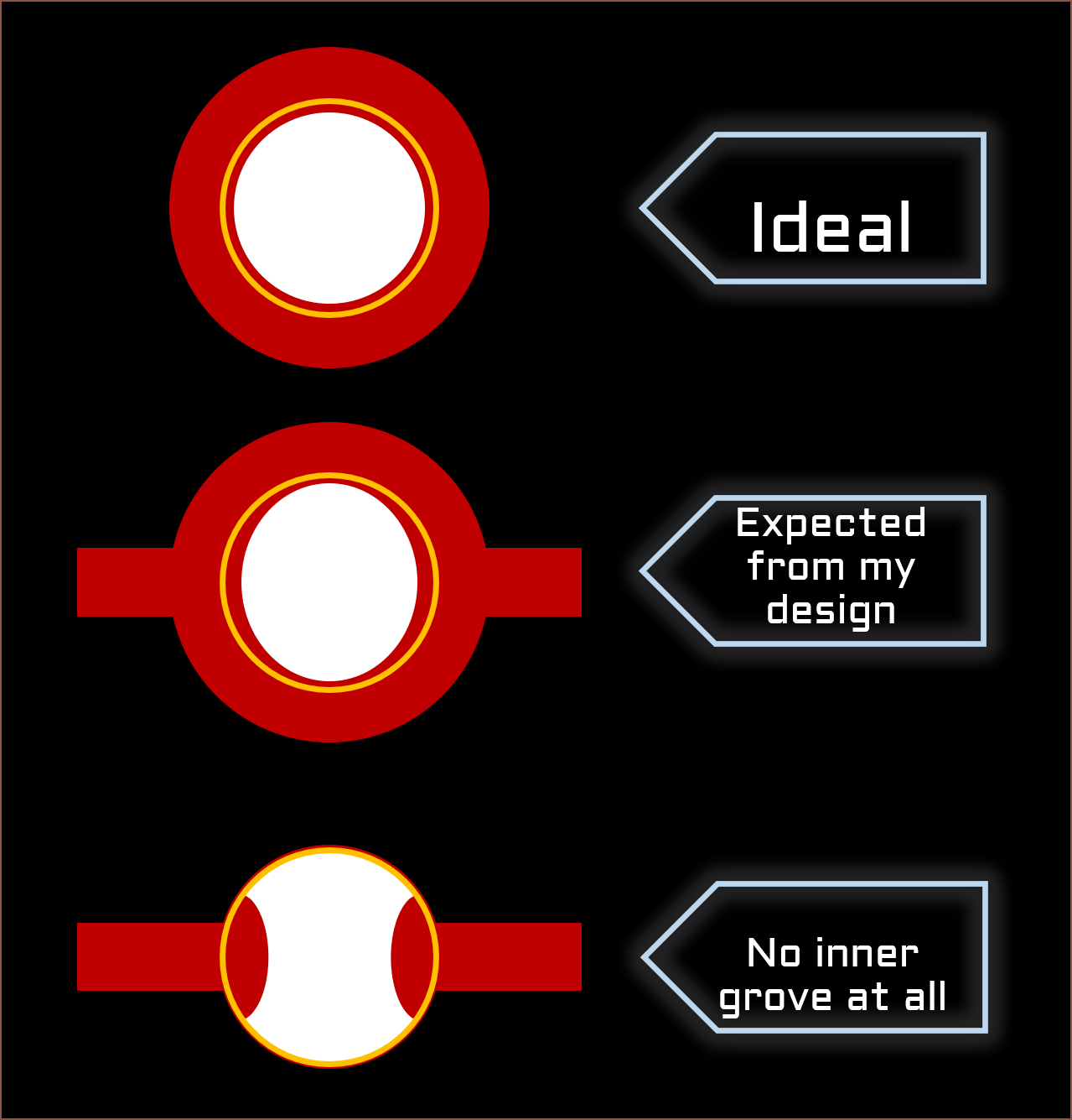
Here is another diagram to illustrate what I mean, whereby the cutting edge is shown by a gold ring:
I haven't done any fluid simulations on the bottom two, so it was just a guess as to what the cross sections would look like.
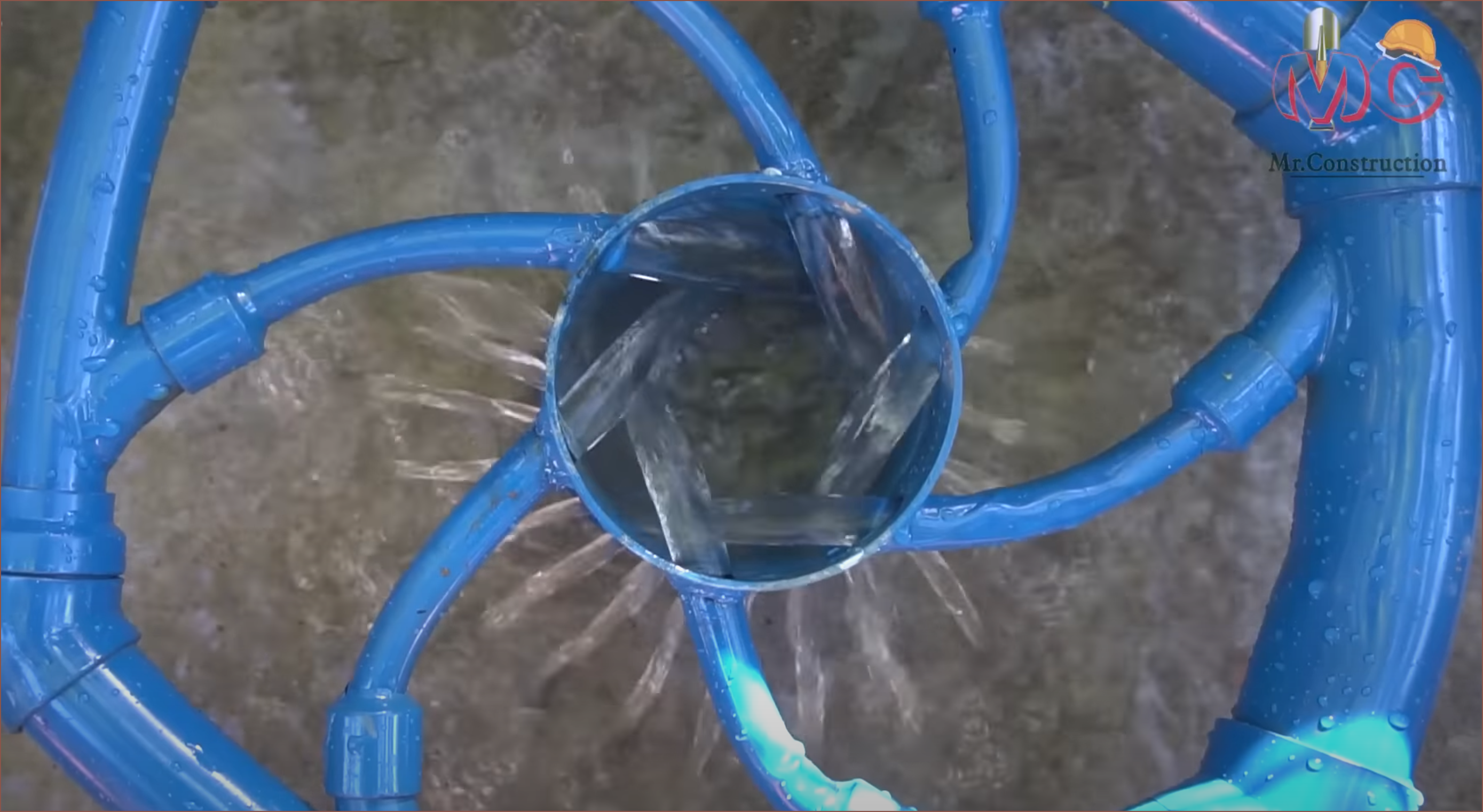
Back to the image I highlighted, it seems that, as the acrylic paint is less viscous than the thermoplastic that Heinz used in his first version, the pressure differences are more apparent, looking like this:
[2024 - Jan 13] I found out that the yellow and red inputs heinz used were for the mixing inputs. Thus, the actual view likely looks more similar to the diagram with the 2 inputs, such as a squircle instead of an oval. An idea I had after seeing the video was the below design from this video:
I feel that something like this could reduce the pressure differences caused by material emerging from the inlets.
Ideally, only one or two inlets (as shown above) would be needed, but I can imagine that 3 would be the ideal number
3] The mixing is buffered, allowing for faster changes without needing a small volume
This is similar in principle to how the Pallet 3 splices material before it goes into the hotend, I believe this hotend does something similar within the hotend:
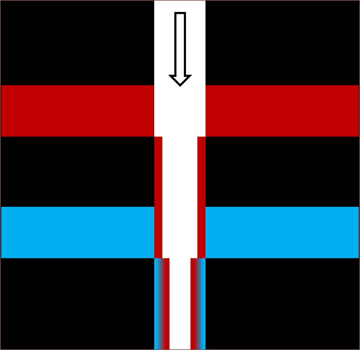
As you might already be able to see, this ties in with my next hypothesis point:
4] The diffuse distance is short
As it has been seen from typical N-in 1-out hotends, one angle of the finished print is predominantly one colour and another angle is predominantly a different colour. Heinz has also looked into using this phenomenon for multi-colour prints with a rotating nozzle.
The angle where the colours blend the best is actually the middle of these two angles. This is also where the two materials contact. What this hotend does is take this thin strip where the different materials meet and revolves it around the outer surface. The colour of a material is typically only seen from light reflected from the surface of it, and the depth increases the more transparent the material is, so this is ideal.
-
[A] Mystery CNC Price Hike
06/08/2023 at 08:52 • 0 commentsI can only imagine that part of it is because I haven't provided a tech drawing (I wanted to see the price without threads) and part of it because of the filleted internal grooves, but even in the ideal case it'll probably still be >$20 more than the threadless 3D printing option. Or maybe this part is harder to make in aluminium instead of brass?
It sure sounds like the second attempt is going to be a 3D print, though I need to be able to avoid the $30 thread cost without the nozzle / heatbreaks leaking. I might just see if I can 3D print the bottoming M6 threads and then all I'd have to do is simply tap 3 M3 holes. I might model in 2 holes for each cartridge so that there's a spare one if I have trouble tapping the first one.
Additionally, I'd need to change the geometry of the internal channels to ensure that they actually print properly. 1mm diamond square, anyone? The height of the block is likely to be near 30mm but it's better to be conservative when I'm not a company with a fat R+D budget.
Coaxial8or [gd0144]
Full-colour FFF? Multi-materials with unparalleled interlayer bond strength? Abrasives without abrasion?
 kelvinA
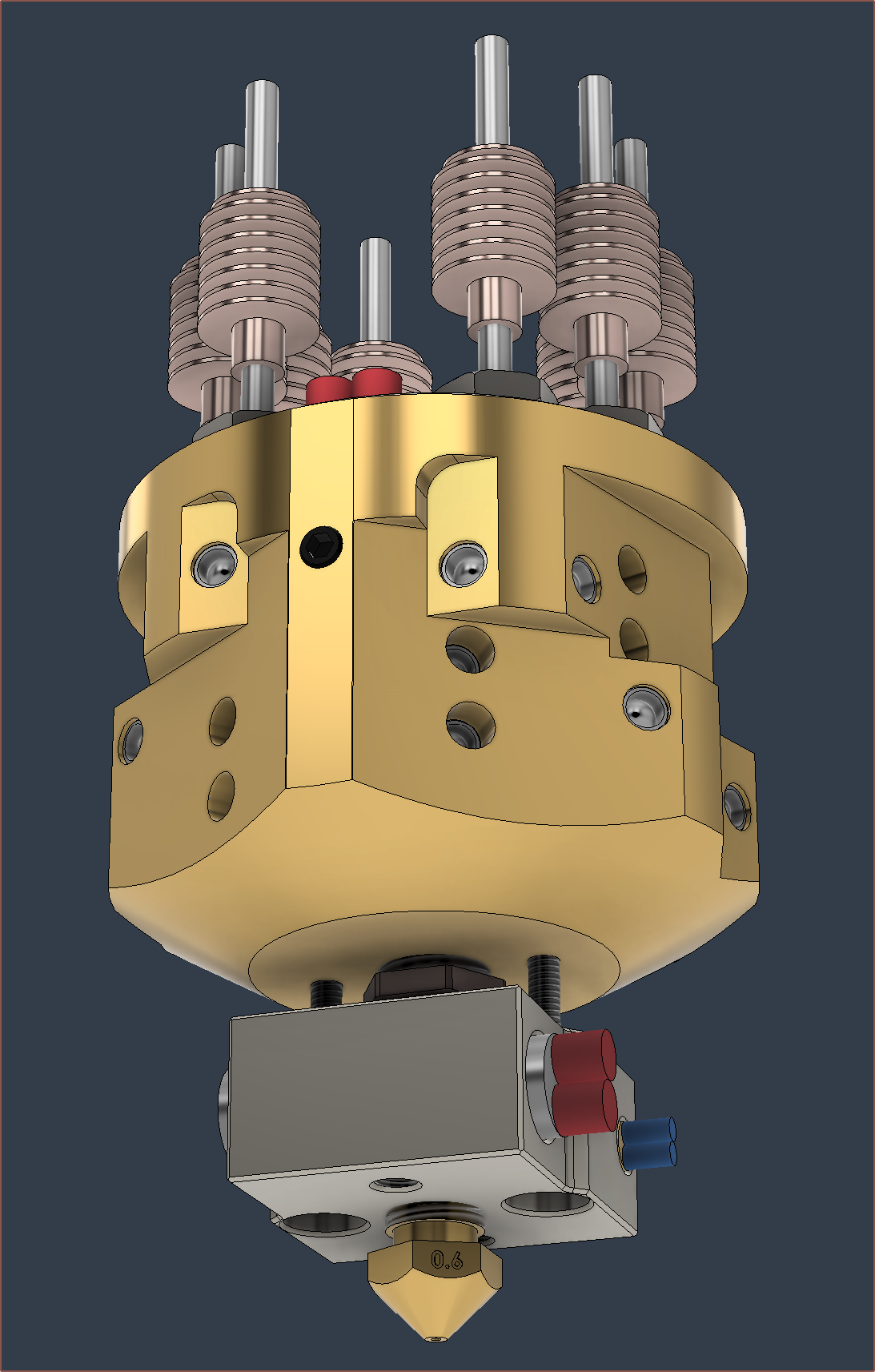 Fusion says that the bounding box is about 40x40x81mm and that the mass is 307g.
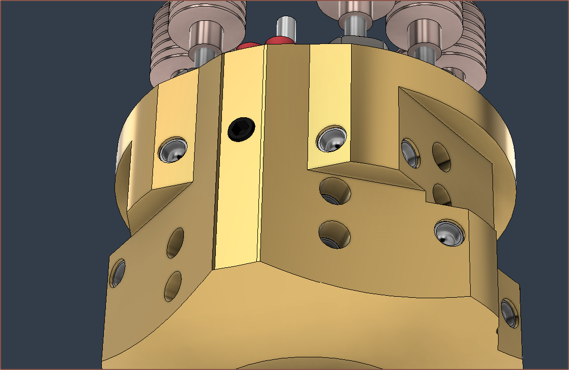
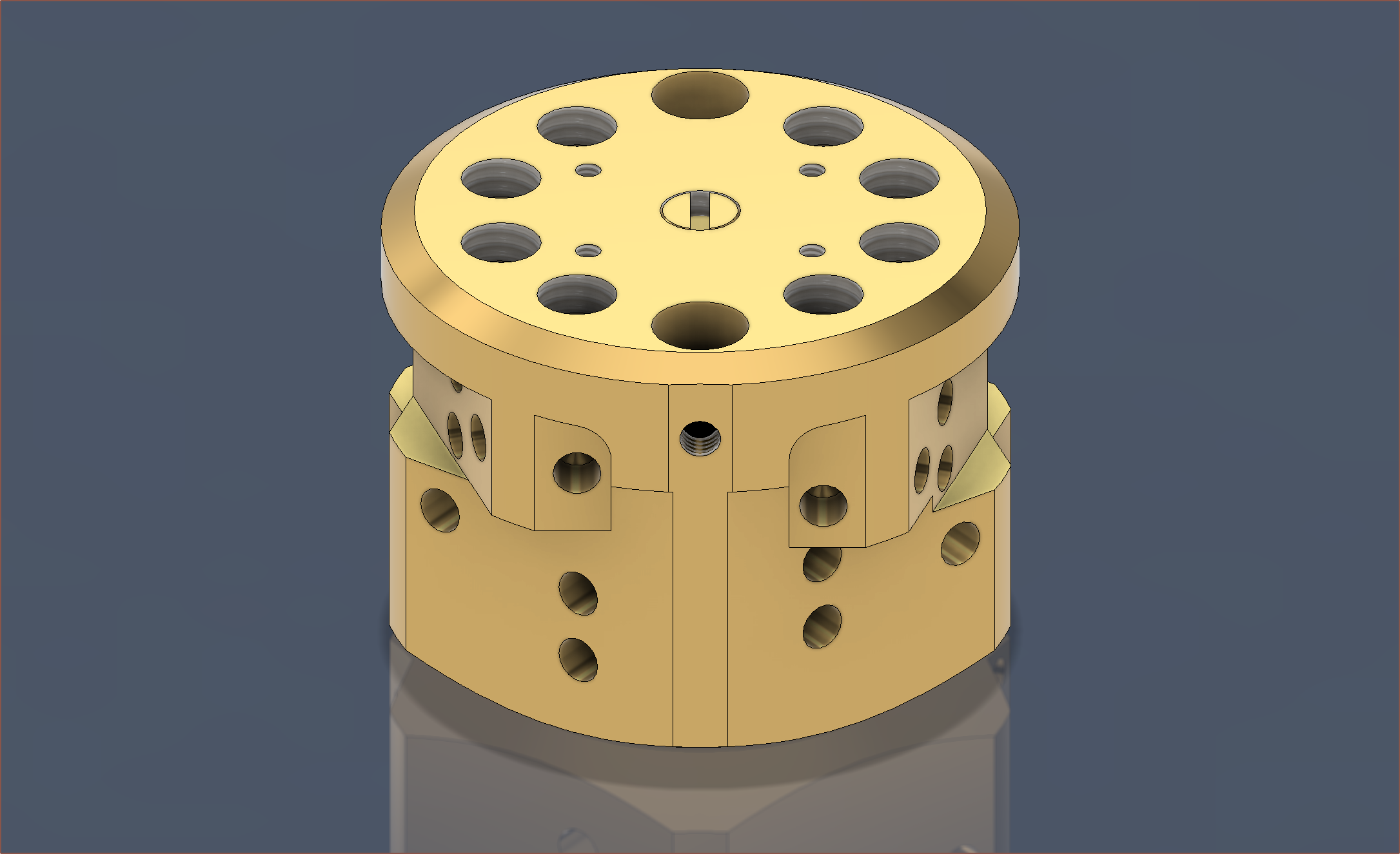
 Then I spent some hours on the redesign:
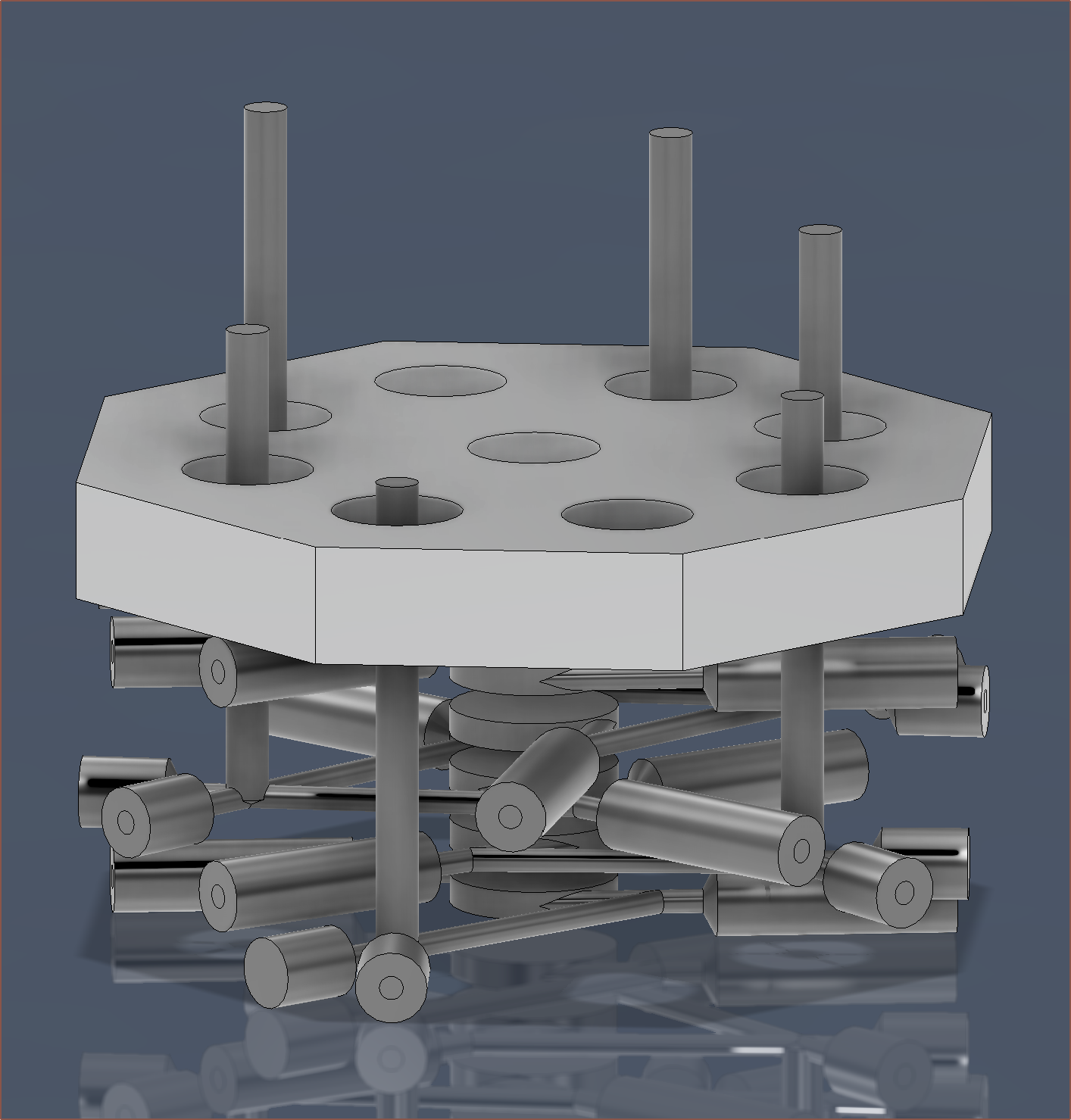

 It slightly intersects with the thermistor hole, but I'm only planning to screw into a max depth of 3mm so it should be fine.
 I've moved the thermistor, reduced the bite of the nozzle down to 4mm, increased the chamfer height to 4mm and rotated the additional block 180 degrees (so that the thermistor wires can be bundled together).




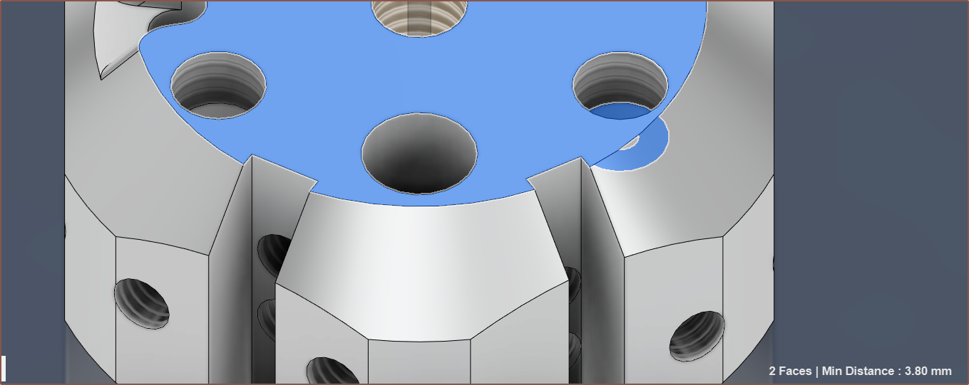 I've also had to reduce the depth of the heatbreak threads to prevent the topmost grub void from creating holes in the mating face. I've ensured there's at least 1mm of wall thickness.
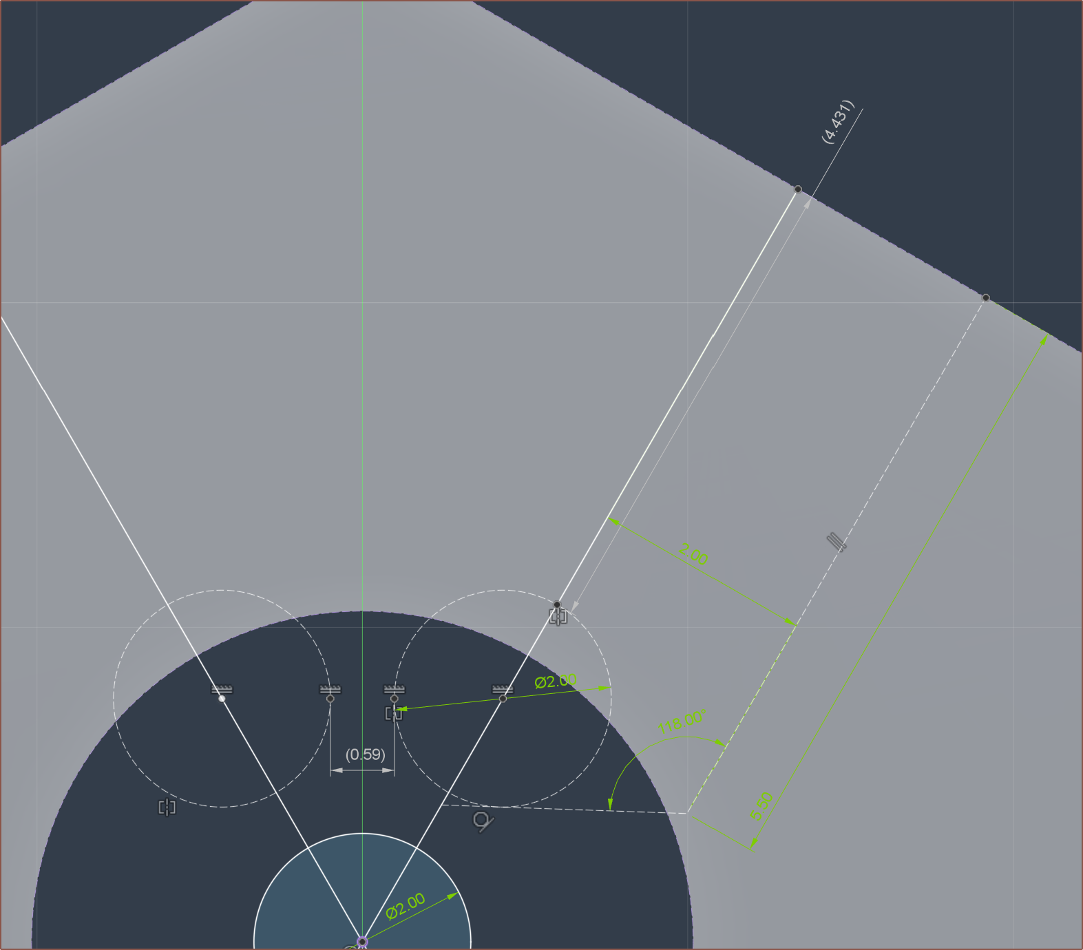 Using a 2mm ball, and a 4mm grub screw, the top of the screw should be just-about below the surface. It might be better to use a 2.5mm bearing to be even closer to the exact length.