I just watched the above video and noticed that the 6 colour Pikachu print likely only needs 4 colours:
Solid Colours
White
Black
Red
Yellow
Composite Colours
Pink: White + Red
Brown: Yellow + Black, with a dash of Red
Considering that the U1 has been the most funded kickstarter I've seen, as well as the vast majority of current AMS-style printers having 4 spools, I'm getting the impression that a 4-input hotend that can blend colours well and transition fast has more... "community relevance currency?" than an 8-input hotend that allows one to forgo buying the entire rainbow's worth of filament. The most notable drawback is that I doubt an off-the-shelf nozzle exists.
I am wondering if not having something daily-driveable is causing side effects of hesitation in my other projects. You know, "Ah, I designed this cool thing in CAD but it's stuck in the virtual realm until I decide on a manufacturing solution". The U1 is affordable at an estimated £999, but that can bankroll a lot of Coaxial8or prototypes. Honestly, the real reason I'm skipping the Snapmaker is because of its build size and that the #SlimeSaver [gd0105] concept exists.
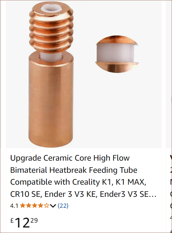
I was scrolling Amazon, searching for ceramic heaters when I stumbled upon a ceramic heatbreak, which is not something I've seen before.
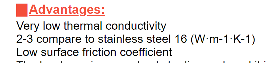
I thought ceramics would be too heat conductive (I mean, they make heaters with it) and too fragile to work, but if it's not the case, it would make a lot of sense since ceramic bearings have even lower friction than stainless steel ones, so perhaps that low friction translates to polymers. I did more searching on AliExpress and found out that Fysetc and Trianglelab both make such heatbreaks, and I was surprised to find out how low the thermal conductivity is:
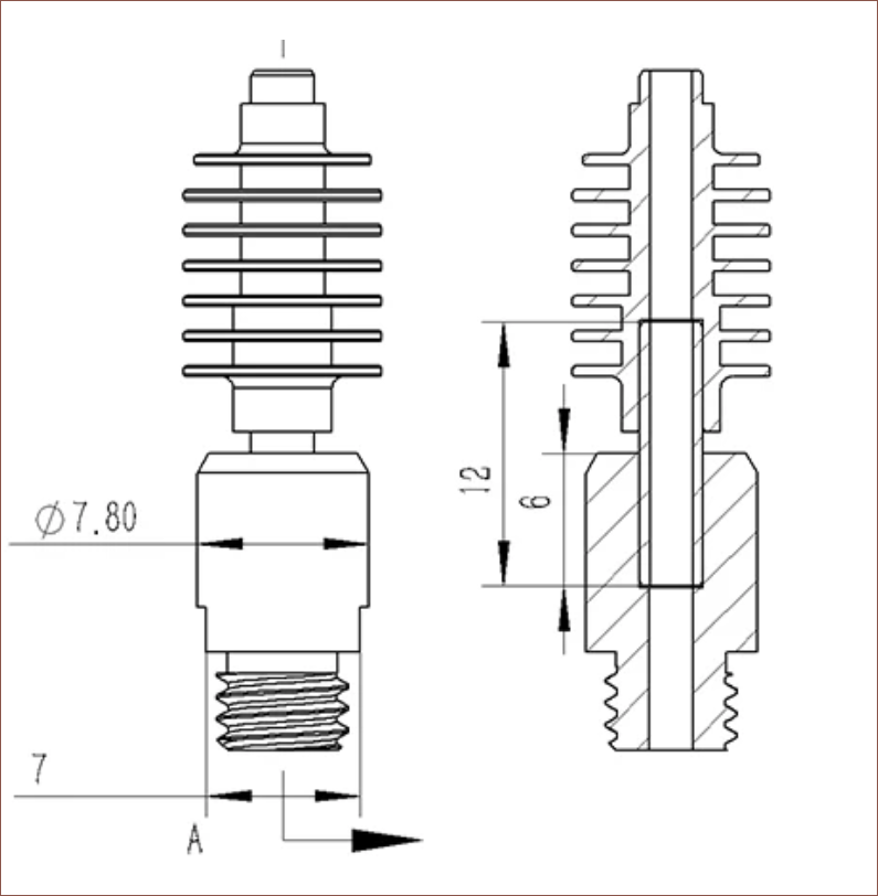
Trianglelab conveniently has a section view and were able to tell me that the tube is "tightly fitted". Comparing pixels, I estimate that the OD of the tube is 2.9mm.
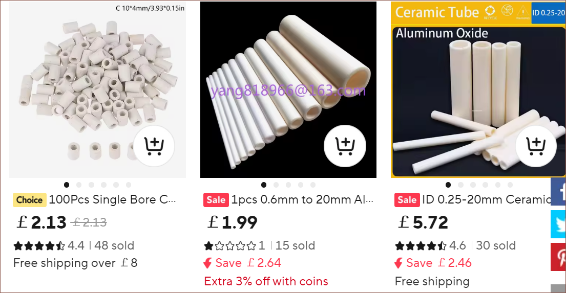
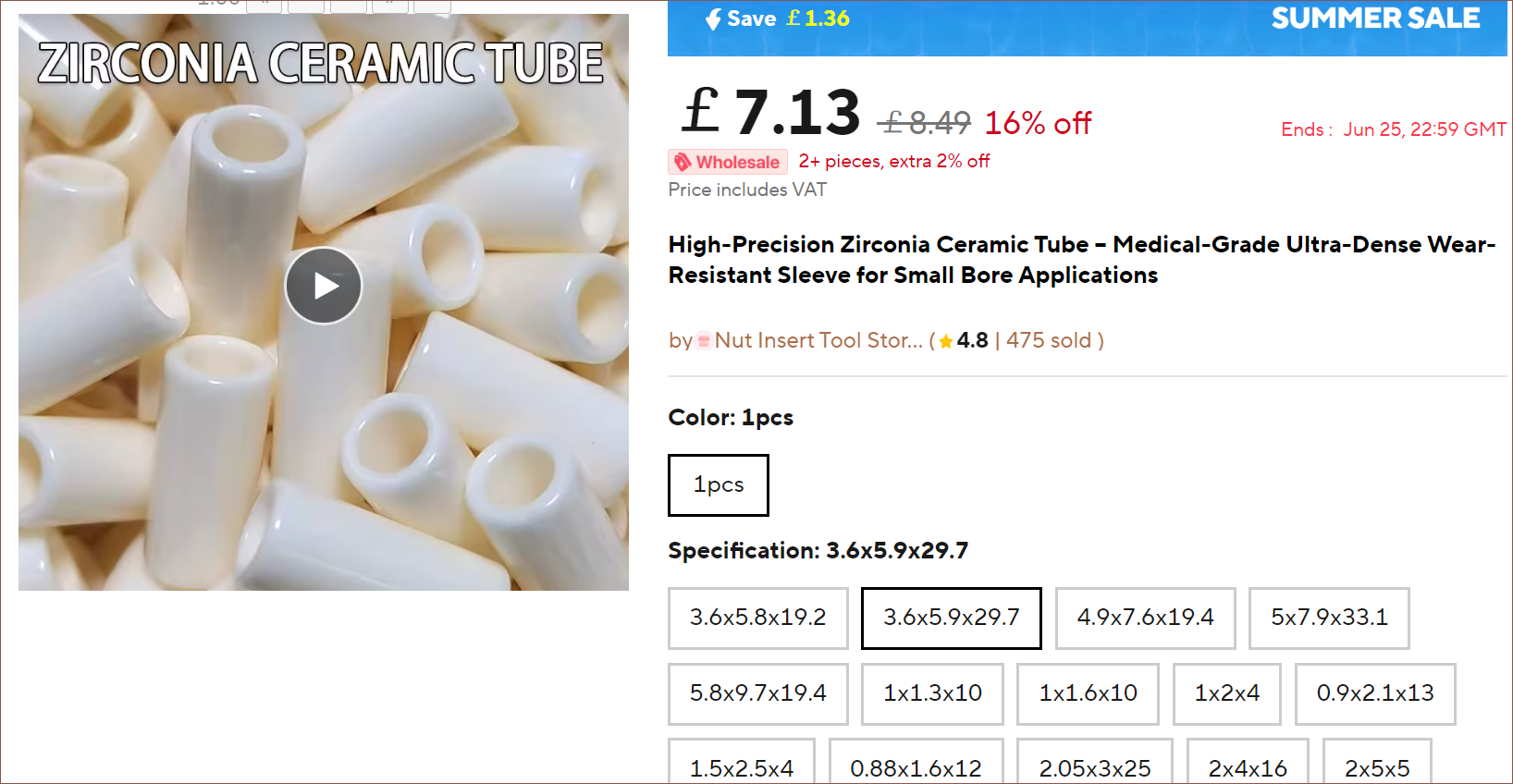
The first tubes I found were low-cost but also had a matte surface finish. I then found some precision polished zirconia tubes in a variety of sizes, most notably 2x4x16mm and 2.05x3x25mm.
The only thing is that this costs £2 more than what Fysetc charges for their entire heatbreak. £7 for a 2.05x3x25mm tube implies £3.50 for a tube half its length.
I looked into it and, as I probably should've known, "ceramics" is about as precise as saying something is made of "metal" or "plastic". On AliExpress, there seem to be 2 types: Alumina and Zirconia. The former is 10x more heat conductive at 27 W/(m.K). NF goes one step beyond and uses "aerospace materials" for their NF Zone, which has a removeable black heatbreak so I don't even know what it could be:
Source, who tested that it was possible to print PLA without a cooling fan and not experience clogs.
On AliExpress, there are also quartz capillary tubes which might be a cheaper alternative that has a similarly low thermal conductivity, but they likely would be too fragile.
I've done a bit of thinking, and for me, the most important feature I need in a printer is being able to switch between stiff TPU and support material, reason being that TPU has some of the best interlayer adhesion and stiff TPU (such as the Kexcelled 64D) should have more nylon-like stiffness, resulting in parts that aren't floppy.
Stiff TPU should also be able to extrude via the BMG clones I have. One thing I learned in the last few months of my degree is that these clones really can't push the usual 90A TPU. I could never get it to print for more than 1 minute on a "short Bowden" (a.k.a. almost a direct drive but there's an approx. 5cm PTFE tube between the extruder and hotend), and one time I had to disassemble a Bowden extruder because another student obviously assumed it would work better than some cheap-looking stock Ender-3 extruder. I need to write up my master's project to #SlimeSaver [gd0105] one of these days, but against all expectations, a stock Ender-3 extruder and its Anycubic Ultrabase clone print-bed allowed me to print the TPU dispenser/scraper 2-in-1 prototypes I needed to progress.
Anyway, I need drastically faster changes
I recently saw someone with a Sovol SV08 that's been modified to have both IDEX and TIDEX, or put another way, 2 extruders on the first X gantry and a third extruder on a second X gantry. This allows relatively quick changes of 3 materials:
I saw this and naturally thought of the Cetus2, which most likely is the limit of FFF transition speed:
Additionally, I watched the following video about the current landscape of MMUs and tool-changers:
Many comments share the sentiment that the Bondtech INDX is taking all the air out of the room. Using the prices Bondtech said they were targeting, one redditor calculated that a 5-tool SV08 would cost merely $995, bringing its overall feature set extremely close to a Prusa XL.
What's the current market of dual-material printers?
Now that I'm now a "recent graduate", I can't just stroll in and use the 3D printers my uni just happened to have... which is part of the reason I even went there in the first place actually 😂. In 2021, all my printers were varying degrees of broken, and in 2025... nothings really changed if I objectively look at things in black or white, working or not working. So obviously, "as [any] 21st century kid would", I went online window shopping.
Other than the (out-of-business speedrun) SCEOAN and their Windstorm S1 (see below), the sleekest 3D printer -- maybe even the sleekest machine -- I've ever seen, I couldn't find anything notable, certainly nothing that could print with dedicated support material on the regular. The multi-material market feels the same as in 2019, just with the Prusa XL and Bambu Lab H2D sprinkled in. If anything, it feels like there are slightly fewer options than the last time I checked all those years ago. Allegedly there used to be a Sovol SV04 but I don't see it on their website today.
Is it a render? Is it the actual product? I genuinely don't know because it actually looks that clean IRL! It allegedly had an MSRP of £399, and it's current £110 price likely reflects that there's no warranty/spare parts.
It honestly looks like a prop made out of silver and black cardboard. BigTreeTech TFT interface, magnetic bed, auto bed levelling, linear rails, direct drive with a hotend that uses those new ceramic rectangle heaters... if this had IDEX I probably would've bought 3 already because £329 is the price I would've expected for a single pringle.
The top frame slots into the base, 2 screws and bamme it's put together. I also really like the server rack-esque way they've enclosed the main electronics. I'm taking notes for #SlimeSaver [gd0105]. I don't even know how a printer this refined was made by a company that didn't even survive the entirety of 2024.
Back to press-fit tubes
I asked, and my PCBWay service rep recommended at least 0.8mm walls for printing stainless steel, so the print-in-place strategy is out. At the same time, I've been looking into the literature of heatbreaks to find out why they're 2mm -- it's to reduce the friction area of the rubbery-consistency filament between its glass transition and melting temperature -- and I found a blog post from 2009 that confirms what I've always wondered: Would a taper improve performance, similar to draft angles in injection molding?
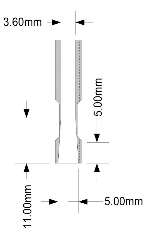
This is the drawing for the heatbreak. In this post, it's shown that a tapered reamer is used.
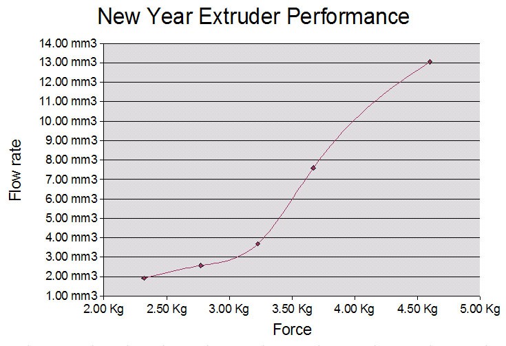
It seems that a tapered heatbreak is particularly well suited to reduce required forces when low flow rates are required, which would naturally be the case for a mixing hotend as any individual input may only contribute a fraction of the final mix.
The author hypothesised that the shallow side of the curve is "where the plug friction dominates".
I remember Deckingman documenting having issues with heat creep, even with PTFE-lined hotends. This idea could be one more thing to increase reliability to an acceptable level.
Moving on, the main idea I've been thinking through is to have the press-fit heatbreak tube go through the entire hotend and stop a bit before the nozzle tip so that the purge volume is relatively tiny. However, this requires very good alignment of the nozzle and the tube, as well as a nozzle that has a larger ID hole. My hope was to use the Bambulab high-melt CHT clones and remove the copper insert and then have two tubes, one acting as alignment. Using pixel sizes, I estimated that the ID of these nozzles are 3.7mm.
The first versions of these insert-based ones were removeable, but I asked around and it seems that current-day ones are press-fit.
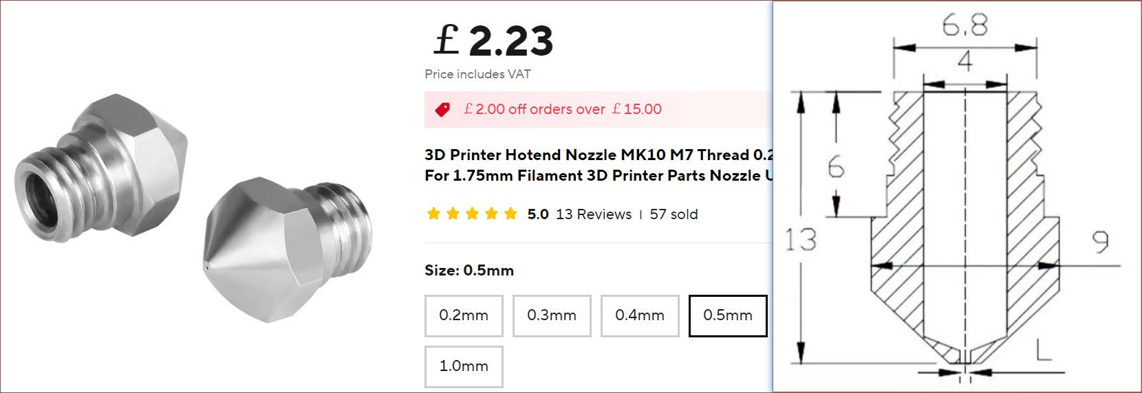
But not all hope is lost. I found a stainless steel MK10 nozzle that conveniently comes in 0.5mm which hopefully gives a bit more resolution than 0.6mm and a bit more flow than 0.4mm:
I'll probably have to use a hexagonal M7 nut.
The outer 4mm OD tube would seal from the inside of the nozzle. The drawback would be that additional length would be needed to hold this tube in place. One of my worries is if this strategy is wise considering that it will essentially double the nozzle length of the coating path.
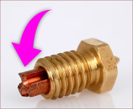
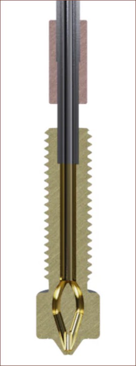
I found the cross-section of a nozzle collaboration between E3D and Creality, and estimate that the tube OD is 2.7mm and extends 4.5mm into the nozzle:
Seems that the tube is machined to have 3 discrete segments. One is in the copper section so that it can be positioned accurately on the length of the tube.
To keep the cross-sectional area approximately the same, I'd be looking for a tube that's 4mm OD 3.2mm ID.
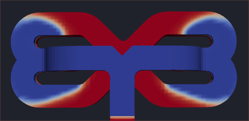
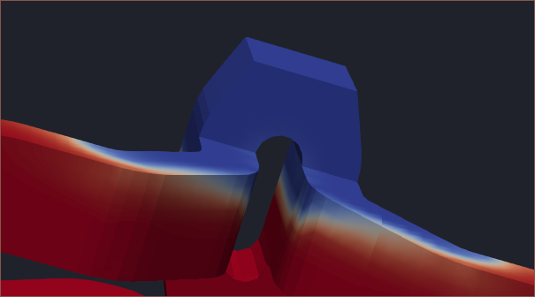
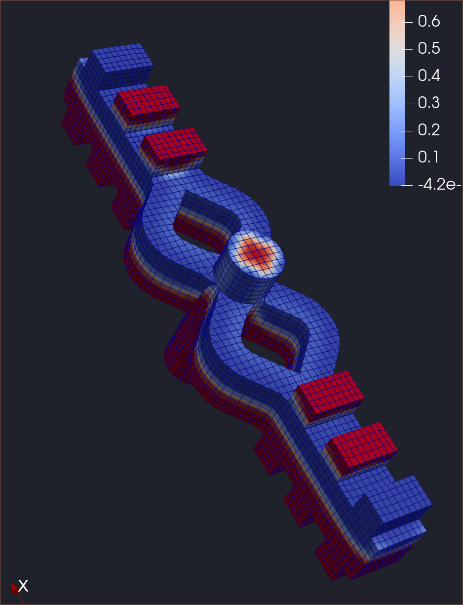
Molten material is highlighted in blue.
Wait a second. Now that I'm looking at the nozzle again as I type this, perhaps it's possible to use that cylindrical section to center the nozzle? That could at least open up the possibility of having 3 coaxial channels inside the nozzle, though that may require the innermost tube to be 2mm. The cylindrical section is also only 1.5mm, so tolerances for everything to fit might get tight. Similar tolerances worked for the Bowden couplers and heatsinks, so perhaps it's fine?
Another question mark would be how the multilayered molten material will move around. Will it coaxialise as desired or will there be some "clipping" of layers?
Thinking back to the very first video of Nozzleboss's #Co-Extrusion mixing nozzle for FDM prints, the changes already looked rather sharp, so I wonder if this additional complexity is reasonable.
And lastly, I'm still unsure about the heatvalves
I don't think I want to bother with thermistors and MOSFETs and critical-safety C++ systems and power management, so I want to use a heater that only has around 20W of output power so that the hotend uses around 160W if all 8 inputs are active. At the moment, the only (financially reasonable) option at 24V is to use the 30-ohm RP1010, but I can't find anything that these relatively small heaters are even used in, so I don't have any mounting solutions. Sellers are selling them and buyers are buying them, but for what, I don't know.
Anyway, I did some best-case sketches to see if a solution could ever exist:
One of my first attempts to fit a potential RP1010 heatblock for the heatvalves, consisting of 4.5mm for the actual block and 1.2mm for the thickness of the heater. As you can see, the block is sticking over the edge, thus this solution might intersect with the X-carriage.This brick-road solution is probably the best, but leaves almost no space to actually hold the heater other than by adhesive. At this size suggests that perhaps a cartridge-style is more beneficial.It seems that this solution would still require adhesive, and the cartridge may have to be mounted upside down to prevent wires pressing against the heatsinks.
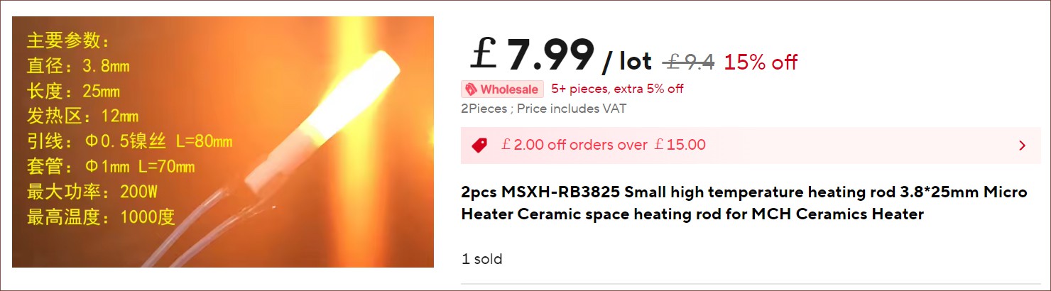
The current cheapest 24V 25W 4mm cartridges are over £15 each on places like AliExpress and allegedly $5 from RobotDigg directly. There's also a 3.8mm MCH (which I presume means Micro Ceramic Heater) but the highest resistance on offer is only 10 ohms.
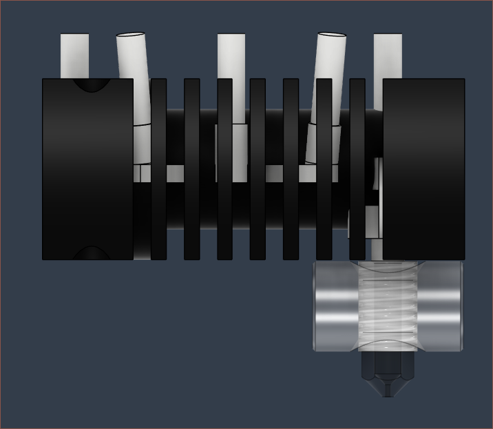
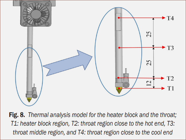
The cartridge is 25mm, of which 12mm actually gets hot.I also found the paper Design of a Throat-extended FDM Extruder for Multi-axis 3D Printing which looks into different parameters affecting a long heatbreak design: From what I understand, air flow speed has the greatest effect on the temperature gradient, followed by the amount of the bumps seen below. They only tested to a maximum of 5 and concluded that it was the best. The evidence is only partially conclusive since they never tested 6+ bumps.I can't see them on the manufactured version, but it seems that the slight bumps on the "throat" are needed for best performance.The heater may have to be permanently affixed in a case that clamps around the stainless tube, but where's the space for that? The alternative was to have one tube each between the heatblock --- heatvalve and heatvalve --- heatsink and have the heater be removable somehow. There's also the option that the case clips on almost like a Knexx and uses boron nitride paste to keep it in place. Another idea is to have a removeable heatsink (such as the Flashforge solution I mentioned in a previous log) so that the heater could be skewered onto the stainless tube and affixed with a setscrew.
Conclusions
One of the overarching "issues" I've experienced with the Coaxial8or is simply that I go and create a revision knowing that there will be an issue and then grumbling because the issue indeed is an issue. For example, I knew that I had designed the R0 such that it would be hard to clean up after a leak and, sure enough, a leak occurred and it was game over. Thus, it feels imperative that I don't even bother unless all issues I expect are addressed.
Due to the high bar, this project is on thin ice compared to the alternative of sell everything off and waiting for the "Tronxy X5SA 400 ft. Bondtech INDX" to drop. Below is the list of all the issues I'm aware of:
Threaded heatbreaks are prone to leaks when there's 8 potential leak locations, especially when materials with differing thermal expansion coefficients are present in the assembly.
Printing when a channel isn't loaded will cause a clog.
Unused inputs are expected to clog after about 30-45 minutes of inactivity due to heat creep.
Transitions need to approach that of Cetus2 for at least 2 inputs.
New power supply and electronics enclosure; I can't be using that massive 1500W PSU forever, nor can I have the electronics just sitting on foam forever.
Compact holder for 8 filament spools.
Part cooling needs to be redesigned.
The pre-melt zone needs to be around 20mm long for reasonable flow rates.
The costs because of the arbor press and custom heatsink and heatvalve components.
Attaching a low-cost heater to the heatvalve such that the heater can be replaced in the event of a fault.
Trivia: I've been thinking and writing this log from 7:30am to 3:45pm. That's 8+ hours. I've been listening to Burn Water - Eunoia (Nostalgic Beauty) so it's felt pretty chill.
I wondered if it would be a decent idea to try a solution without the complexity of the heatvalves as more of an engineering sample that focuses on validating if the new internal geometry even reduces the transition volume to an acceptable level.
The above design is 5.0 cm3, which is more than half of R2. This design doesn't use a clamp plate, which contributed another 3.5 cm3 of hot-metal volume to R2. However, since I'm still unsure about being able to use boron nitride paste to hold the cartridges, this value is likely to increase.
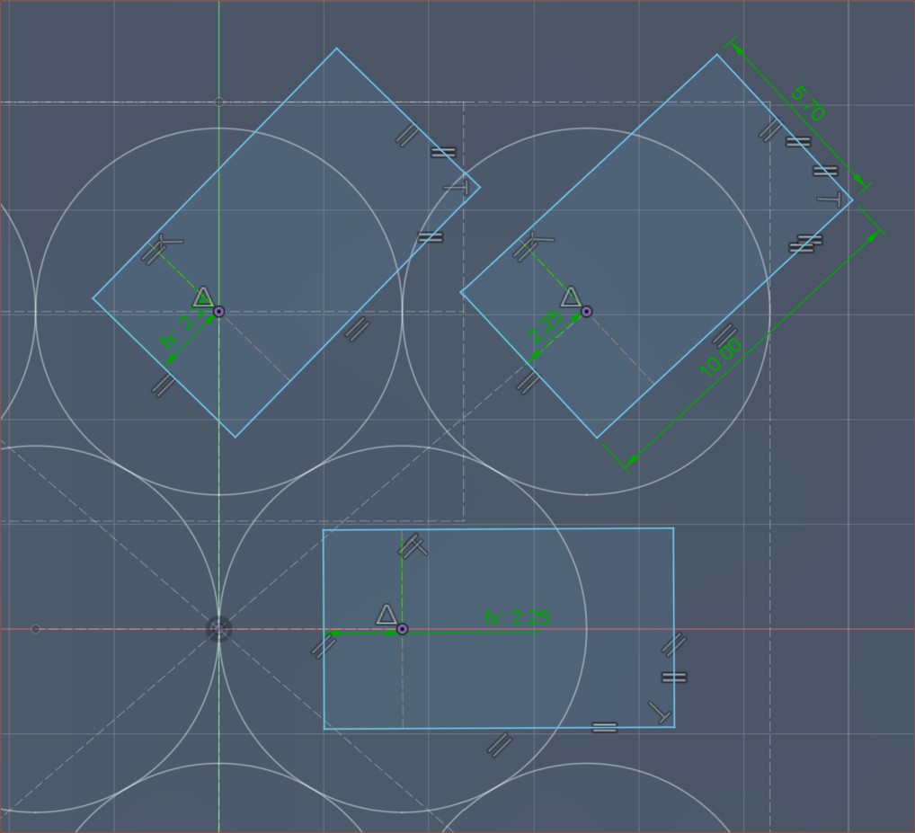
The spacing between inputs is 10.5mm. I tried 10mm (like in previous revisions) but the front-corner inputs come too close to the coaxialiser.
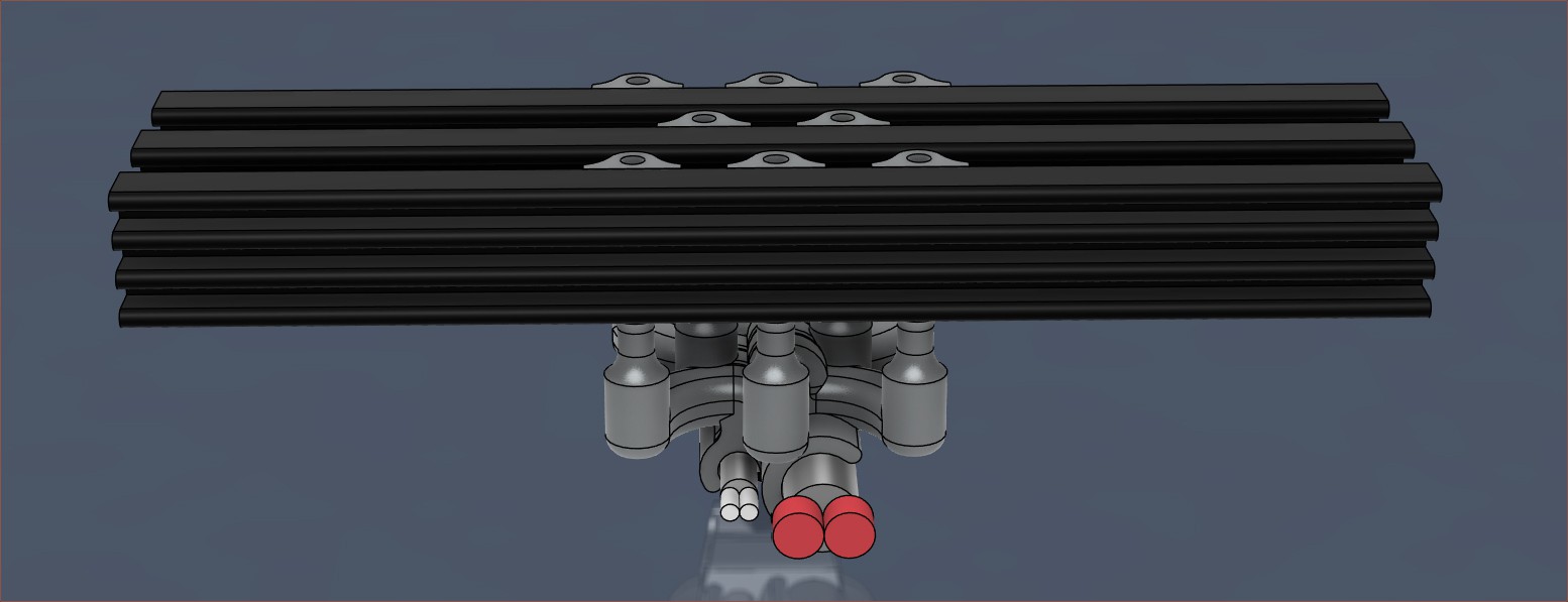
I tried to squeeze the heatbreaks to as little volume as possible because they really do add up when there are 8 of them. They also have to be short to ensure that the drill (and reamer) can reach. Each one is 0.23 cm3. There's only a little less than 6mm of space between rows, so I considered both heatpipes and heatsinks. I modelled 2 different 5mm-high heatsinks I found on AliExpress:
50 x 11 x 5mm100 x 11 x 5mm
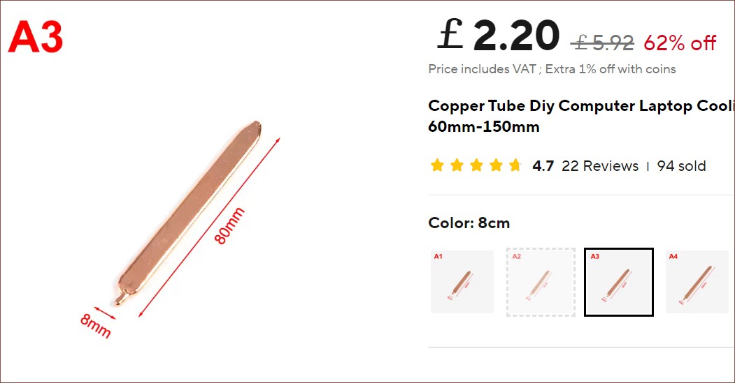
When divided by 3, the 100mm one is a little over 1000 mm2 per input. For aluminium, this might be too low. Even if it was adequate, fitting the fan would likely be a challenge. Thus, the heatpipe option is more likely; the flat ones on AliExpress are 8mm wide and 3mm tall, starting at 60mm long.
This seller has 10mm increments starting from 60mm, but most sellers start at 100mm with 50mm increments.
DOI: 10.13140/RG.2.2.16367.87206 Name: Fused Deposition Manufacturing of Multiple Materials via Co-extrusion
I'm not really sure how I even stumbled on this paper. I was just looking for SLM-printed hotends and learning why the heatbreak length is usually 2mm. I didn't think I'd find a 2020 thesis paper of a guy called Robert trying to make a coaxial hotend. This hotend was just to see if the desired extrusion was possible and wasn't connected to a motion system. Here's what I learned:
Fabrication: Binder jetting from i.materialse and Shapeways, starting at 60% stainless / 40% bronze and eventually going for 100% stainless due to heat conductivity.
He had to split up parts a lot because the parts kept coming in with powder! Is SLM less susceptible to this, or has PCBWay just not got that skill issue?
One of the issues from this is that the "shell" input only came in from one side, causing the extrusion to be pushed
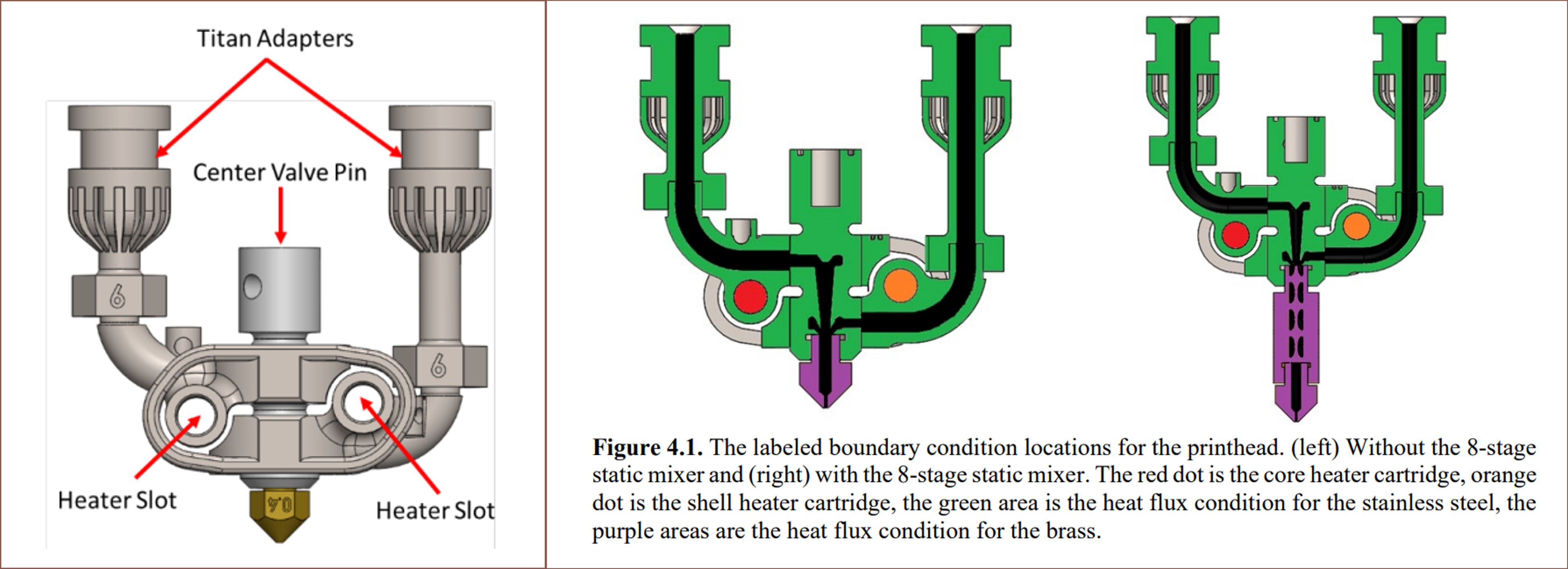
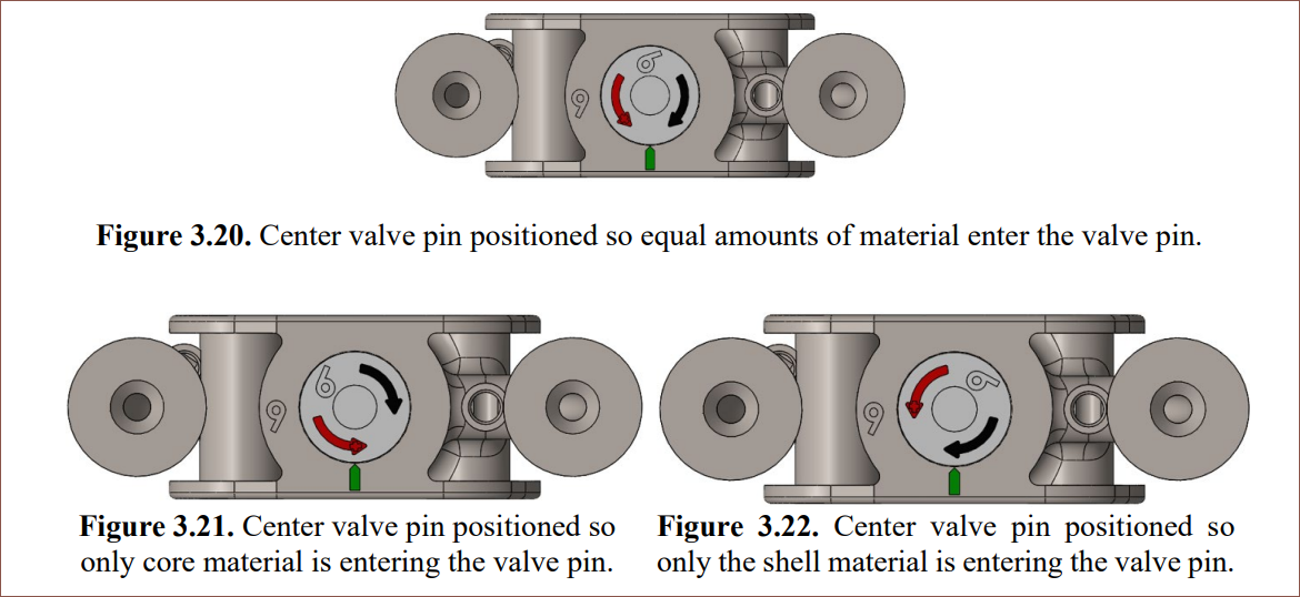
Design: Essentially all-in-one. Since it wasn't mentioned till rather later, it seems that Robert assumed that each input needs to be thermally isolated for use of materials with different melting temperatures. The center pin generally averages out the temperatures anyway. He had flow issues that he attributed to the complex internal geometry, but I believe it's because he's trying to bend semi-molten filament. Interestingly, the centre valve pin can be rotated:
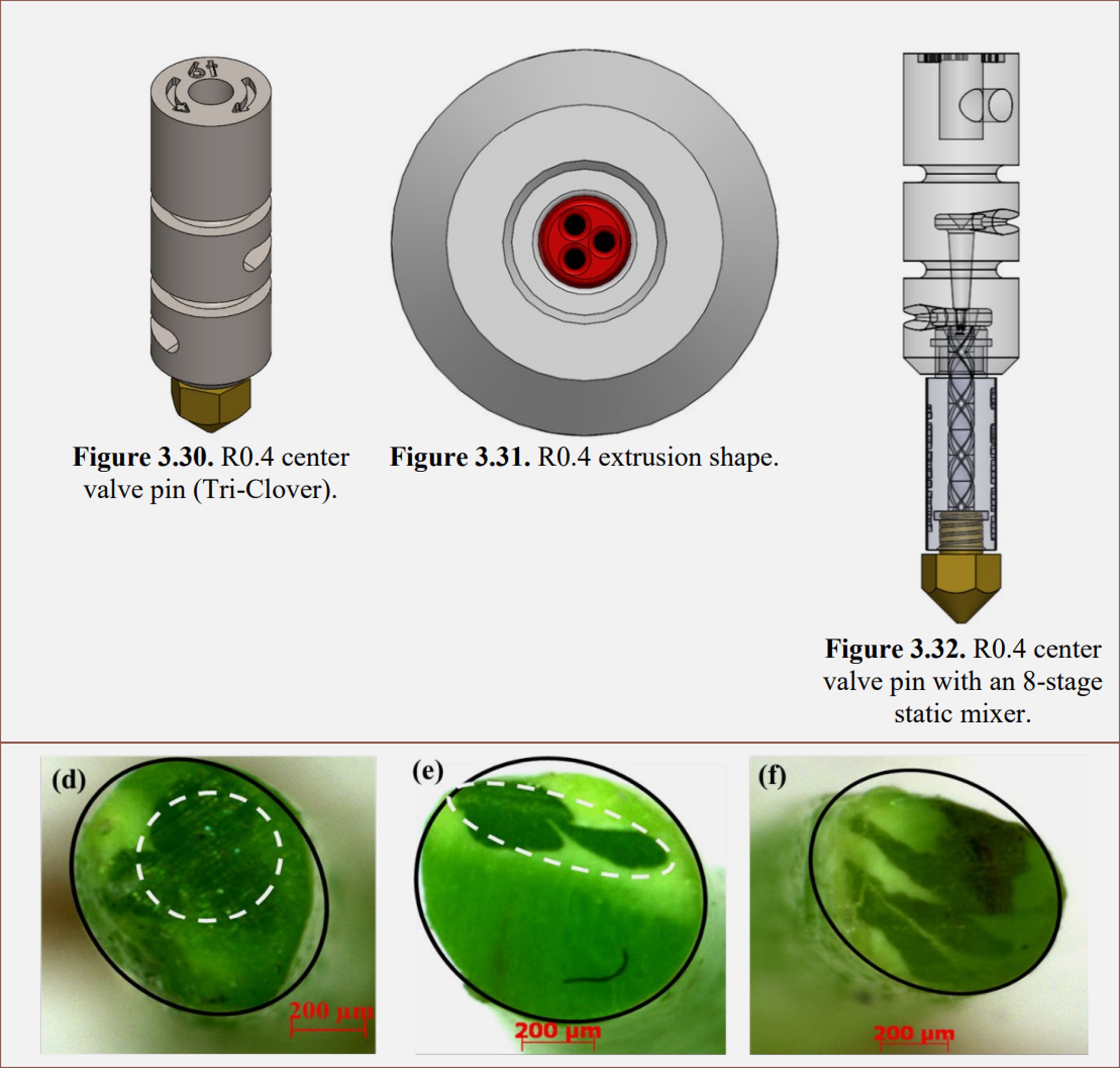
One of the unique pin designs was one that had 3 smaller holes instead of one. At high shell amounts, the core got pushed to a side. The static mixer just made some layering effect in the extrusion.
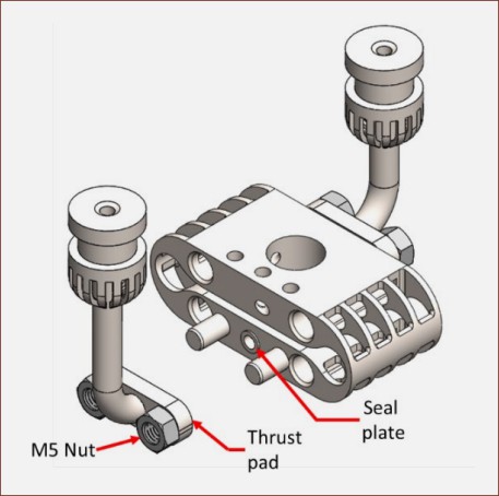
Not sure how it's being sealed though. While on the subject, in an earlier design, he added a "seal plate" which looks like the geometry I added to Coaxial8or R3:
He still uses Marlin's mix feature and had to use the bed heater to control the second cartridge. If you remember back for Coaxial8or R0, I used the chamber heater.
I noticed the little gap around the sealing face of the nozzle, so he probably knew about the whole bottoming-thread thing.
Oddly enough, only single material flow simulations were conducted.
He put switches so that the cooling fan can be turned off to allow material to heat up in the cooler section to clear blockages.
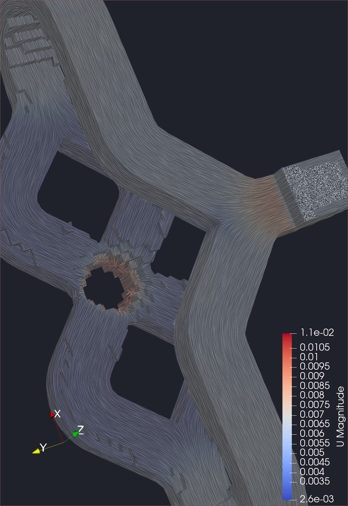
Further work was simulating 2 different polymer flows and mounting to a "hobbyist printer (e.g., CR-10, Ender 3, Prusa) to support streamlined integration", which I've respectively kinda-done and done. His intent for the simulation was to visualise the cross section; I believe the OpenFOAM simulations I've run are viscous Newtonian fluids and they seem to do a good enough job.
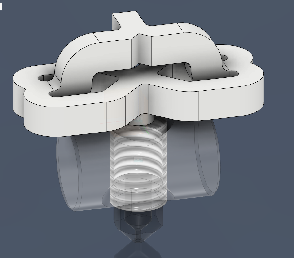
This design is 3.4 cm3.I modelled the idea I had during the conclusion stage of the previous log. It's a proof of concept, so the actual 3D file is somewhat fragile at the moment. There's little benefit for perfecting things now when the idea might not even get green-lit by fabs or geometric conflicts arise when designing the heatvalves and heatsinks.
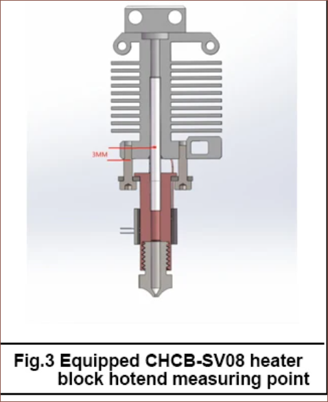
I looked into the old-school all-metal heatbreaks and they use 3.2mm at the tube section. I believe I've also seen more recent hotend designs (like the SV08 in the previous log) use 3mm tube.
Currently, I've modelled 1.8mm ID 2.8mm OD tubes to try and balance powder removal, ease of drilling and lack of heat conduction.
The issue I see at the moment is the sealing of the heatblock to the heatvalve. Perhaps they would have to be integrated too?
I'm not sure how far I'll get before all the additional manufacturing complexity nudges me over the edge to essentially say "Well, it was a good run, but that #SlimeSaver [gd0105] isn't solving itself and still has the optimistic appeal of potential performance." but I've currently modelled a potential heatblock candidate that is about 3.3 cm3.
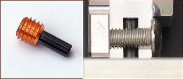
I may have to extend the length of the press-fit tubes, as they're currently 5mm and all examples I've found look like they're >7mm:
Considering that a V6 hotend is installed, the tube does look to be around 7 - 8mm here in this SV08 hotend.
At 7mm, the heatblock is 3.5 cm3.
Series of events
I first designed the heatblock how I've always designed ones in the past, but it seemed to use more material than I'd like:
This was 5.6 cm3; too much when I'm targeting 3.5 cm3 which is the amount for a standard volcano hotend.
I then had the idea to use the Shell command to create the minimum-material-needed heatblock. Only the "rounded" type works anyway. The straight-edged shell would've used more material for little benefit:
The above is 2.6 cm3, proving that a solution within target could exist.
Next, I proceeded to delete a few faces, add the dowel holder, and fillet things:
I think it looks nice, like an engine, so I kept the top non-symmetric like this.The dowel orientation is such because it was easier to make a nicer looking design.I tried the first orientation, but it only saved a negligible amount of material, looked less sleek and I eventually came to the conclusion that there was nowhere else for the heater to go but where the leak path would spill into.
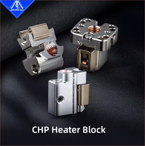
For the heater, an ideal solution might have been the clip Mellow came up with in their CHP hotend:
I don't think the clip alone is available, so I've modelled in geometry for a more traditional cartridge heater/thermistor, attached with nothing but boron nitride paste. They're not enclosed in part to save on material and to allow easy access of water to remove the cartridges if they need replacing.
The cartridges are then insulated with 3mm wool that was used back in a time before silicone socks. Here, I'm using it as a shield against material wisps.It's designed to take a 15mm cartridge, but I'm going to test with a 20mm 70W one.
Closing statements
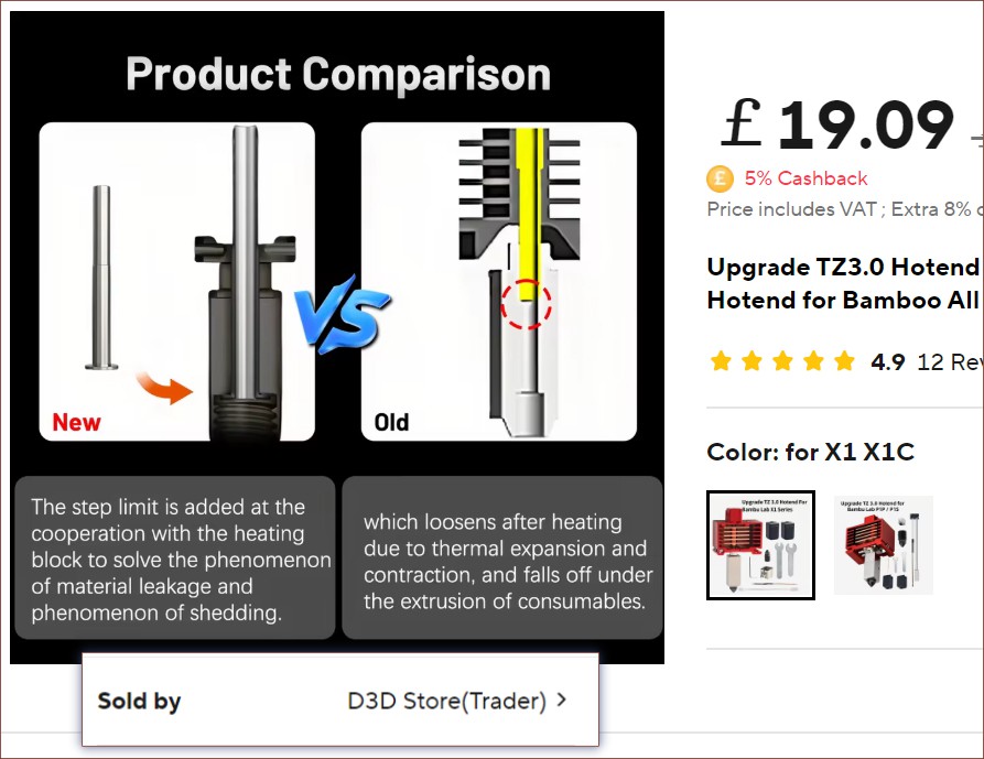
D3D, in their listing for a hotend they sell, does seem to confirm my worries about thermal expansion on this press-fit solution. I'm not sure exactly how thermally conductive this heatblock actually needs to be considering all the twists and turns inside of it, so printing in stainless-steel is still looking the most ideal.
If anything, I might just take a page out of XYZDims and see if PCBWay or JLC can print 0.5mm thin tubes which I drill on the inside. I might have to ream too, but a rougher surface finish would both help with heat transfer of the filament and would actually turn the drawback of those pre-bimetal, chinesium all-metal heartbreaks into a feature by promoting "clogging" when the input is off. It might also save money both in material savings of the printed part but in thin-wall tubing too.
I was wondering if I'd need tolerances similar to the Tetoroidiv rotors and it seems like I do. Charts, machinist forums and Gemini all agree that, for a dowel 6mm or less, the "interference" should be 0.0005 of an inch for a press fit, though one forum-user was able to work with 0.001. In other words, the holes are between 12.7 to 25.4 microns smaller than the precision round object that's going into it. I also found the below video that recommended that the initial hole should be smaller by 70 - 140 microns for 1 - 3 mm holes respectively, meaning that for a 2.5mm reamer, I'd be using a 2.4mm drill to enlarge the roughly printed holes.
Now, since the rest of the world works in metric, the only options for reamers are 2.49 or 2.48mm. Gemini determined that 2.47 would be too much for a solid dowel pin, let alone a thin-walled tube. Speaking of the tube, my plan is to use 1.9 ID x 2.5 OD tube so that there is a tad less expansion space for the molten material and the tube walls give a little more strength than 2.0 ID.
2.49mm is closest to what all the forum-users are using, but Gemini and I did the thermal expansion calculations and the interference would loosen by 4 microns (aka 40%) when heated up to 250C and up. This isn't really an issue for copper, such as the Creality Unicorn nozzles, as both materials have rather similar expansion. I'm considering printing the heatblock in stainless steel from JLC since both the tubes and the cross-dowel pin is stainless steel. I know Dyze uses a non-stainless steel, and in the comments they said it was because of higher thermal conductivity. Obviously, as I've found out in this project, stainless steel is tough stuff.
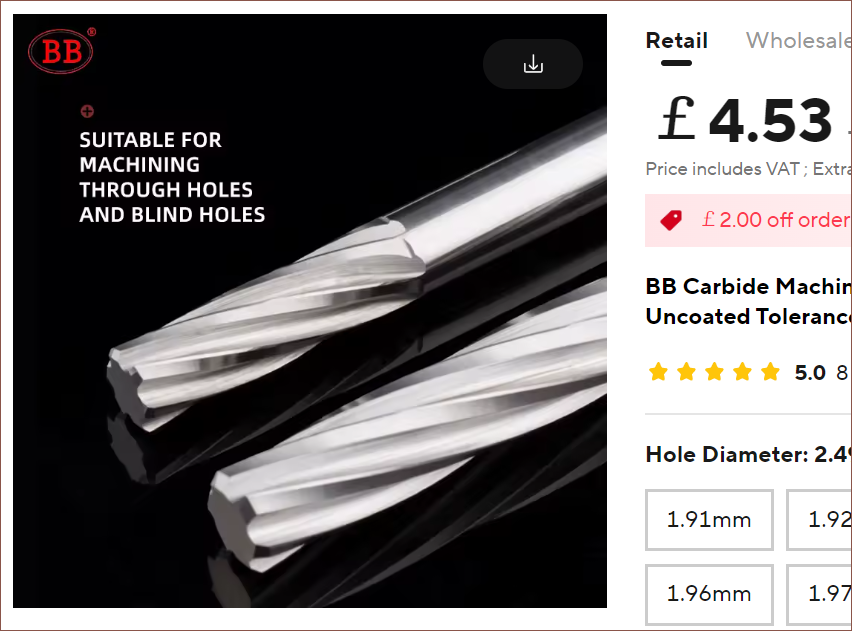
I found some low-cost reamers and drill bits on AliExpress. I thought they'd be way more expensive. I'd have to spring for the coated ones from the other supplier I found if I go through with a stainless steel heatblock either now or in the future:
2.49mm feels a tad too close to the limit, especially since the whole system is pressurised too and there are 8 of these that need to be confidently installed, thus my first choice will be 2.48mm. There's also the option of lightly sanding down the tube if it's too small.
Allegedly, to actually insert the tube, I'll need something called an Arbor Press, which exerts forces measured in tonnes allegedly. I found a white, branded one that does 0.5 tonnes for around £50:
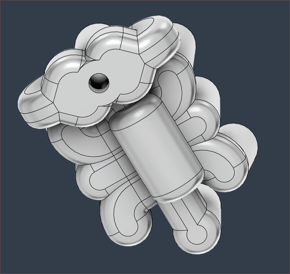
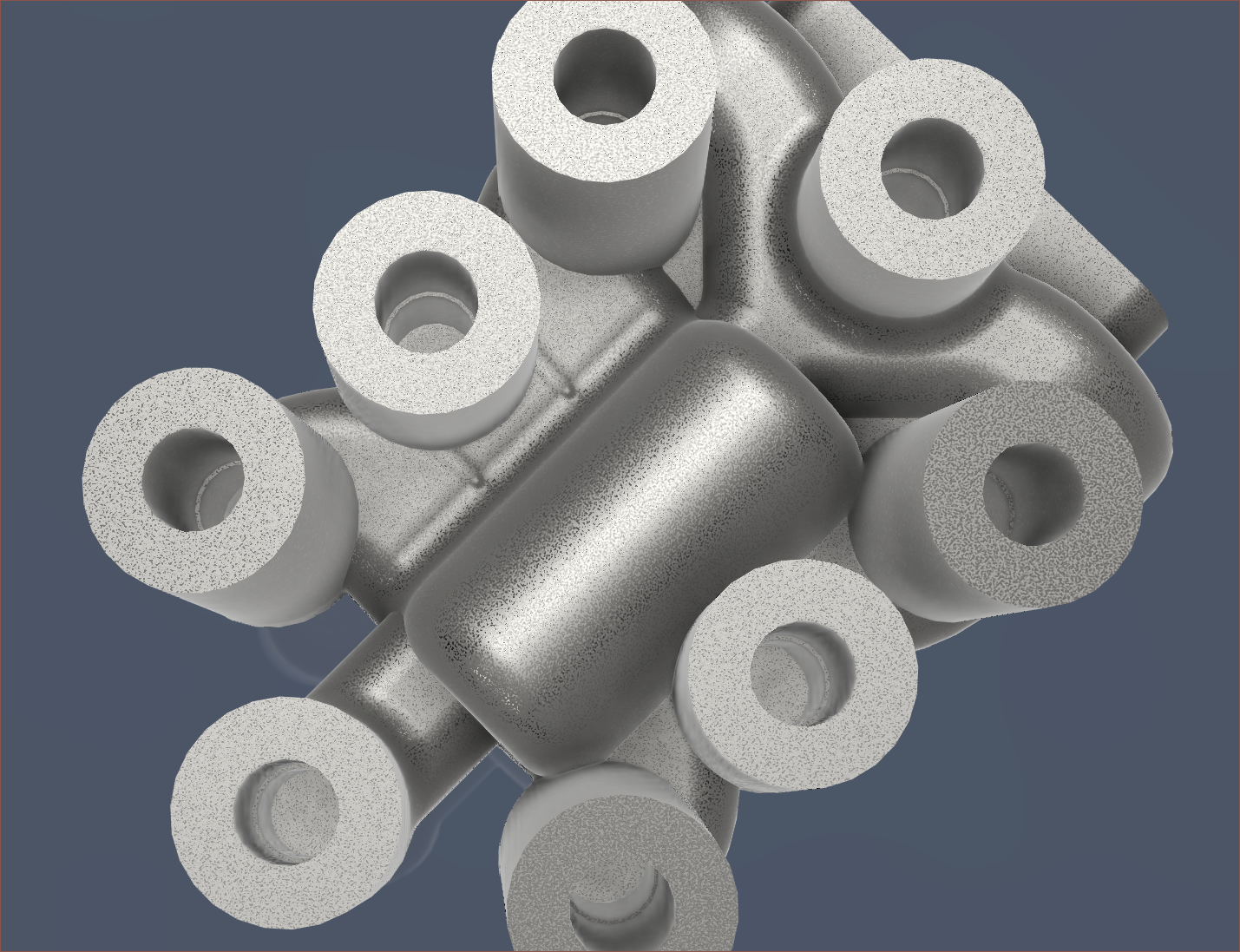
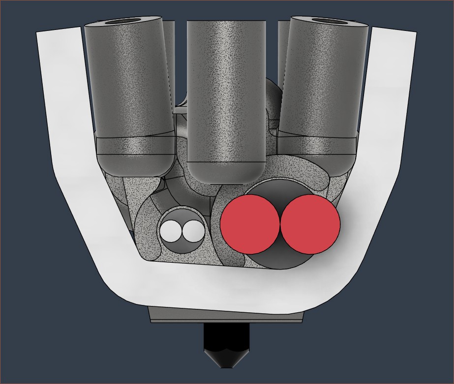
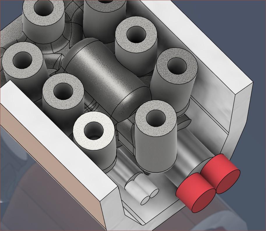
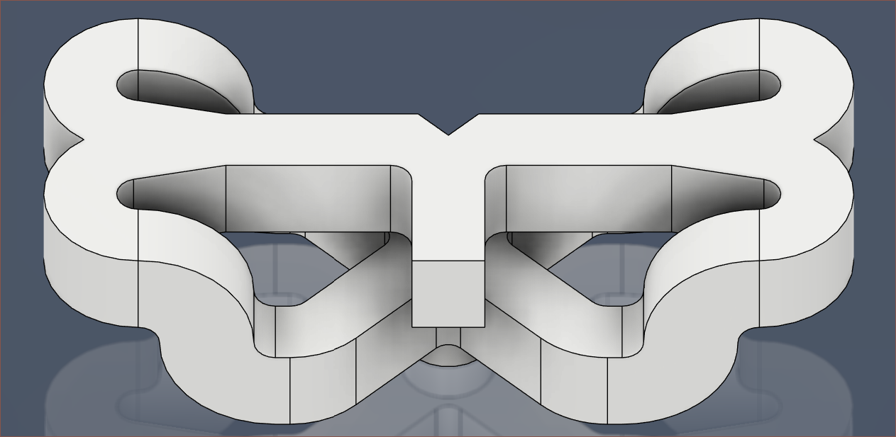
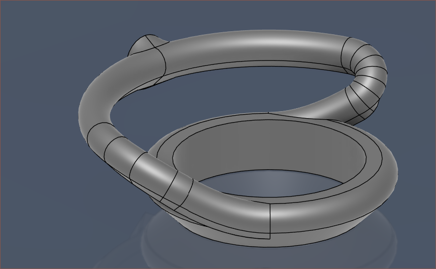
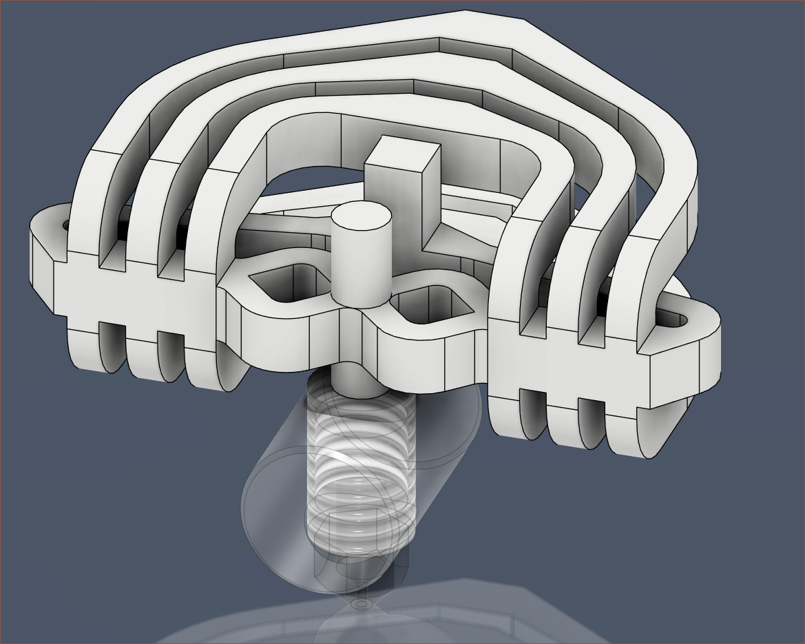
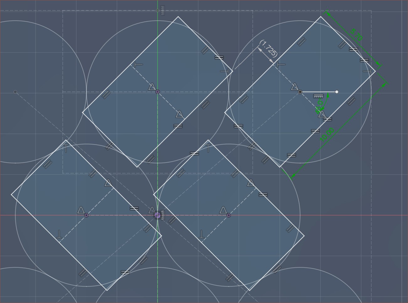
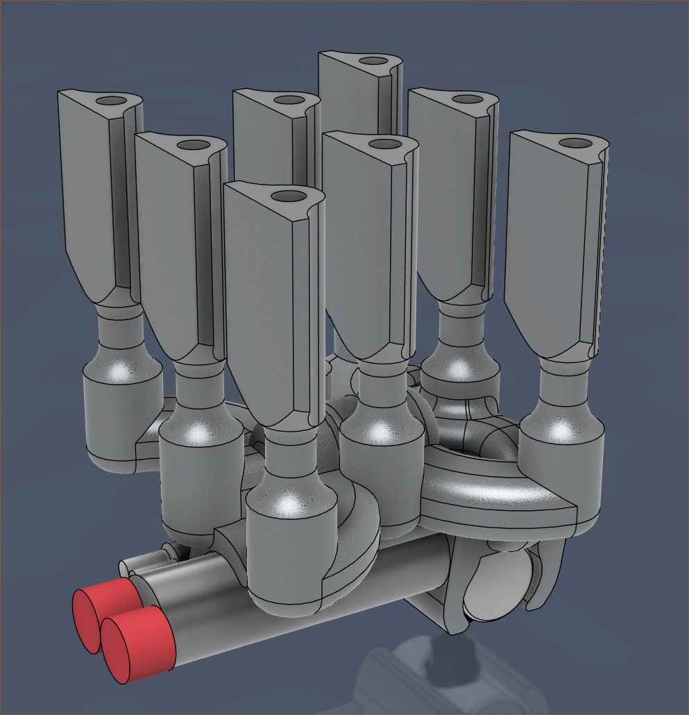
This solution uses approximately 0.6 mm3 of molten plastic. The side inputs are spaced 6mm appart.Here it is. After multiple days of thinking up and simulating multiple ideas, this is currently the smallest pathway solution I've obtained.
All the other things I tried, in chrono order
I started of simply adding 90-degree spikes to cut the material flow and keep everything moving. This had a volume of 234 mm3. I wanted to see if this could be a strategy. It's 20% more volume. These next two designs explored if I could split only after going down a level to save on volume. This is 11% less volume.This one is about the same volume as the first one.
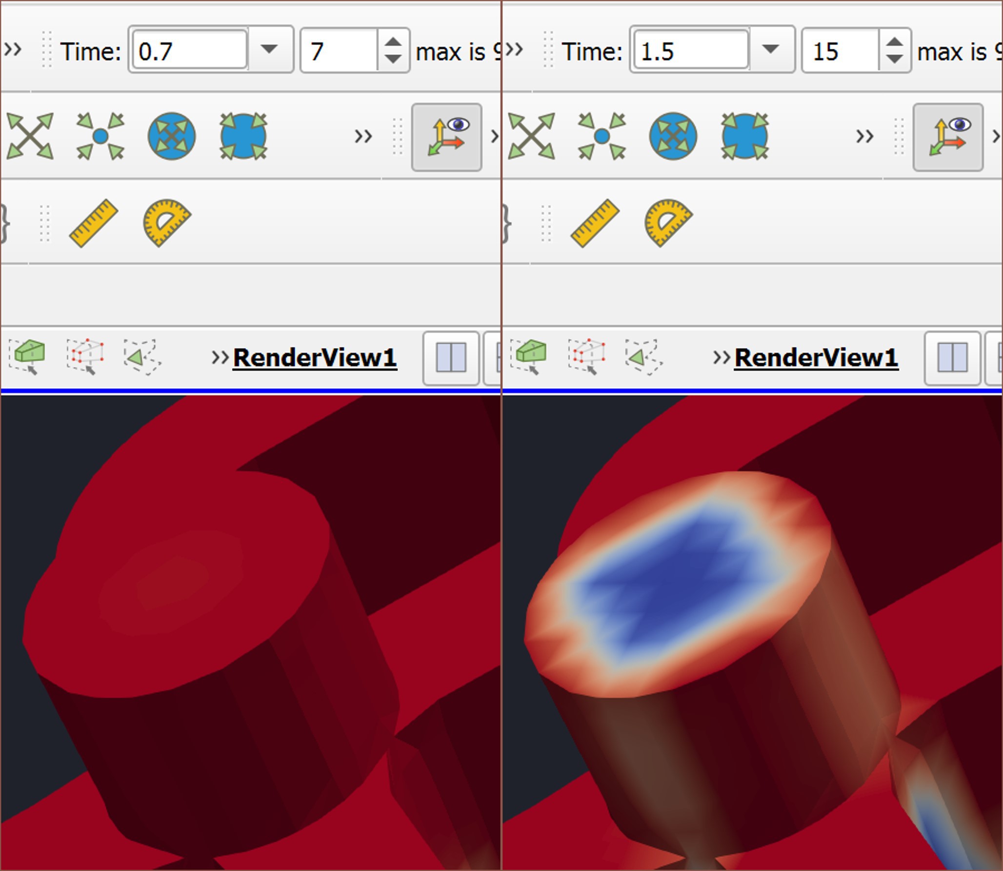
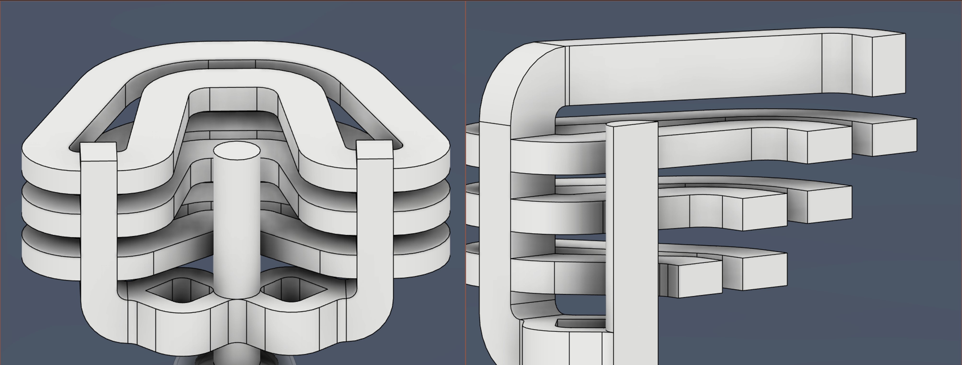
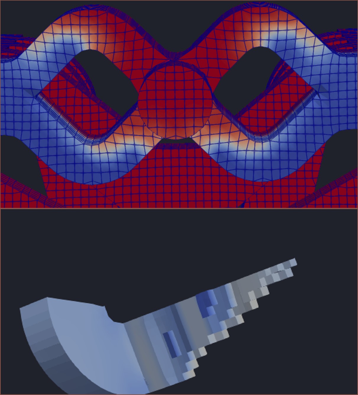
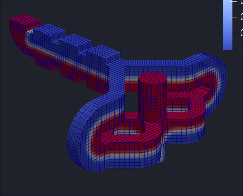
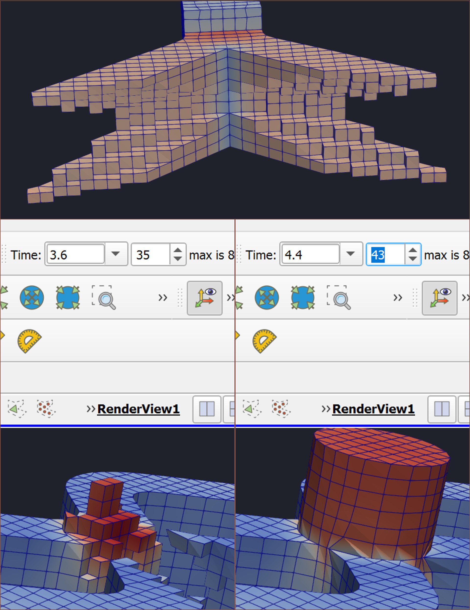
The 4th one seemed to work fine.The pathways were reasonably matched too.The same could not be said with the 3rd idea.I then decided that a reasonable way to further decrease volume and improve side-to-side matching was to make the paths thinner. I also looked at all the view modes ParaView has.LIC was nice because I could see the movement direction of the flow. U magnitude is in m/s.I tried pre-splitting and the transition time was 1.7s. Note that a total of 40 mm3/s is flowing through all these tests. Tried going up instead of down to potentially reduce the amount of material that needs to travel up from the tubes. I was assuming that the tubes would exit lower, accounting for the hole that keeps them in place. Transition was 1.5s.I tried a completely flat design, but transition speed was 1.7s, the same as with the 2nd design.I sent this off to PCBWay and they said that it would be possible to fabricate without powder in the channels.Tried this idea where it's mirrored but I couldn't think of a reason why it would be beneficial.Thought of having a FastPass input so that there could be faster transitions between support and the mix, for example.At this point, I was noticing that my solution was looking like a cleaner version of one section in Coaxial8or R0, but now this geometry for R4 does the job of the 7 rings.The transition takes 0.8s to complete. I was hoping for even less time.I tried seeing if I could split before and have 2 straight channels going straight into the diamond-squares. Obviously, it uses too much pathway material.The transition is 1.0s.In an attempt to reduce the amount of pathways needed, I tried bending upwards and staggering the inputs of these channels so that I could routhe paths in and out.I had quite mismatched channels and the reason was because of the starting condition. Once I fixed this, I had 0.8s transition.Then I ran this simulation and I got 0.9s transition. Then I did a simulation of a full mix change, which completed in 0.8s. I ran the FastPass input simulation afterwards and the transition was 0.6sI tried to loft-curve to save on volume, but it ended up slightly increasing it instead.Then I tried shuffling the inputs around to get a solution that was both symmetrical (to cut down on modelling/fabrication time) and didn't intersect with things. This solution doesn't work with the heatsinks, but I decided to model the internal channels anyway.The end result is barely larger than a CR-10/Ender-3 heatsink.
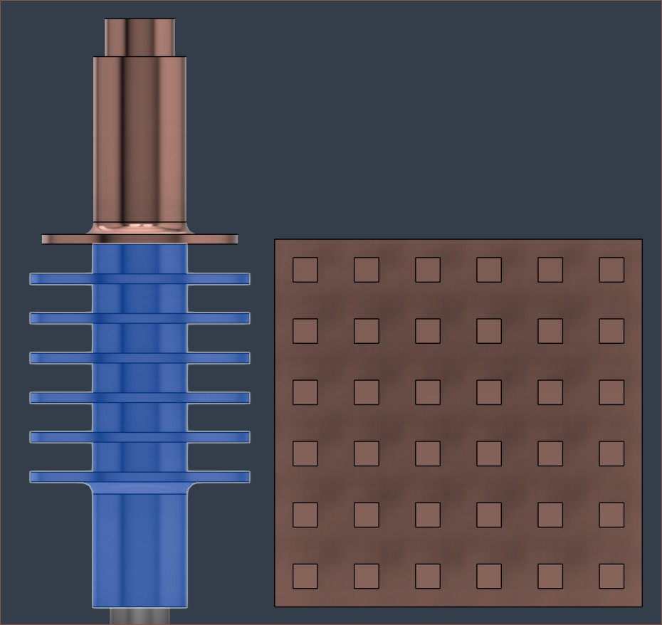
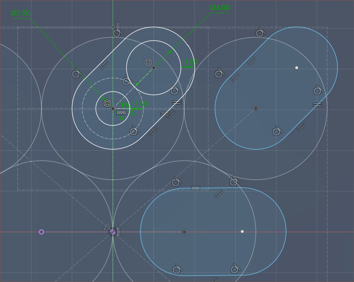
So I was wondering how I'd even know how much cooling was enough, and then I realised that the heatsinks I've got already were shown to work, implying that I just need a heatsink with similar surface area:
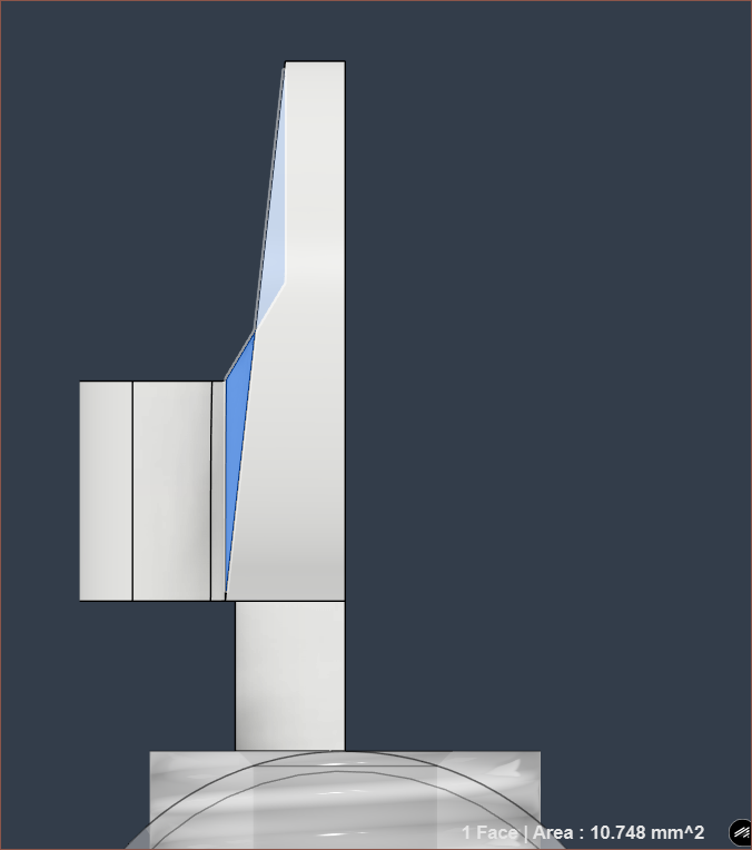
Current heatsink (left) and 15x15mm heatsink (right)
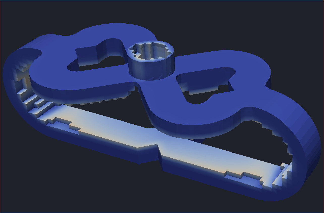
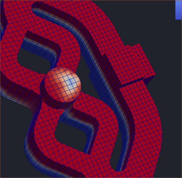
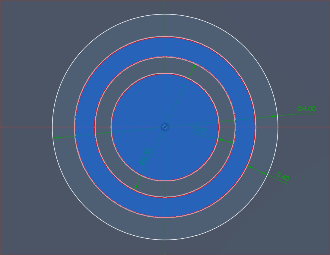
The faces exposed to air in the design are highlighted in blue. I then modelled the 22x8mm and 15x15mm heatsinks.
Current Heatsink: 865 mm^2
22 x 8mm Pin: 836 mm^2 for the top+sides, 716 mm^2 for the top only.
15 x 15mm Pin: 1065 mm^2 for the top+sides, 945 mm^2 for the top only.
The price/volume is £4.52/487 mm^3 and £6.20/630 mm^3 for the 22mm and 15mm heatsinks respectively, so the price is proportional to the amount of copper.
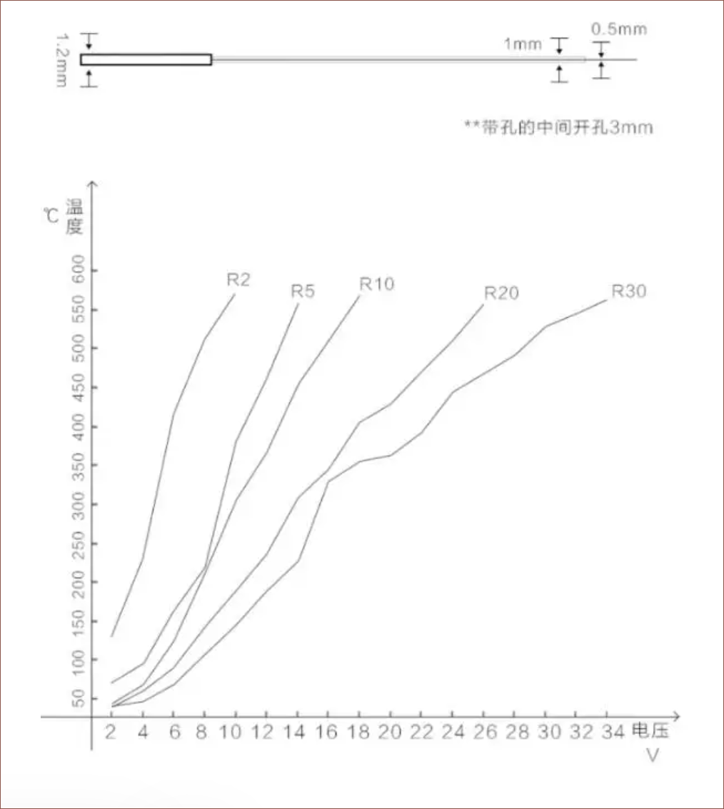
I also found out about the RP1010, a 10x10mm ceramic heating element that comes in a range of resistances and only costs £5.50 for 5pcs. As you can see in the graph below, the 20 and 30 ohm options are suitable for 24V, which corresponds to 29W and 19W of dissipation respectively:
Due to the 15x15mm heatsink having a margin of additional cooling performance, the Flashforge heater is 15mm tall and this RP1010 is a square, it makes the most sense to use it for the next-generation Coaxial8or R4.
 kelvinA


 From what I understand, air flow speed has the greatest effect on the temperature gradient, followed by the amount of the bumps seen below. They only tested to a maximum of 5 and concluded that it was the best. The evidence is only partially conclusive since they never tested 6+ bumps.
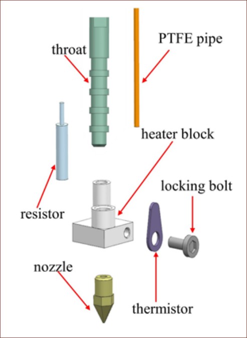


 Currently, I've modelled 1.8mm ID 2.8mm OD tubes to try and balance powder removal, ease of drilling and lack of heat conduction.
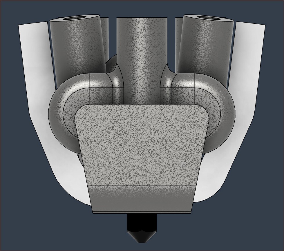 I'm not sure how far I'll get before all the additional manufacturing complexity nudges me over the edge to essentially say "Well, it was a good run, but that