 kelvinA
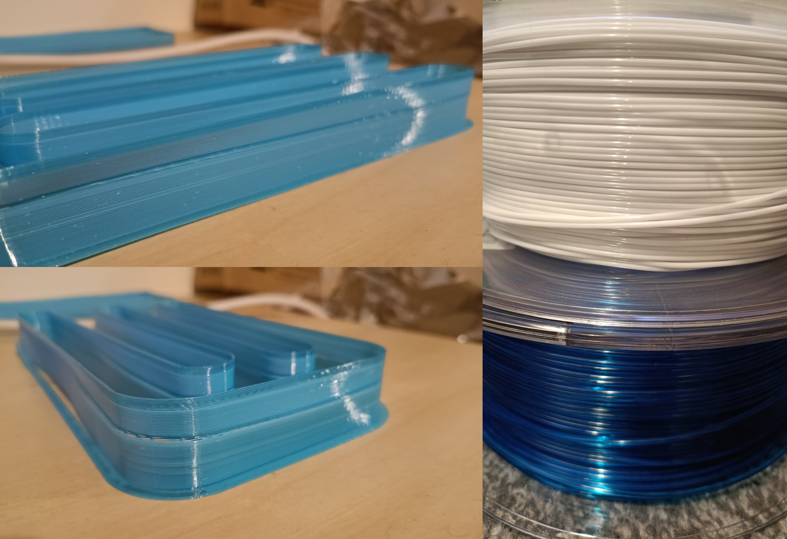
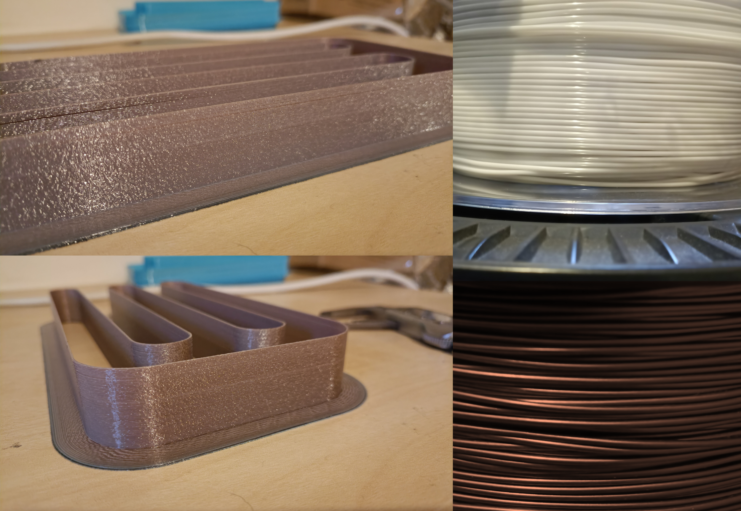
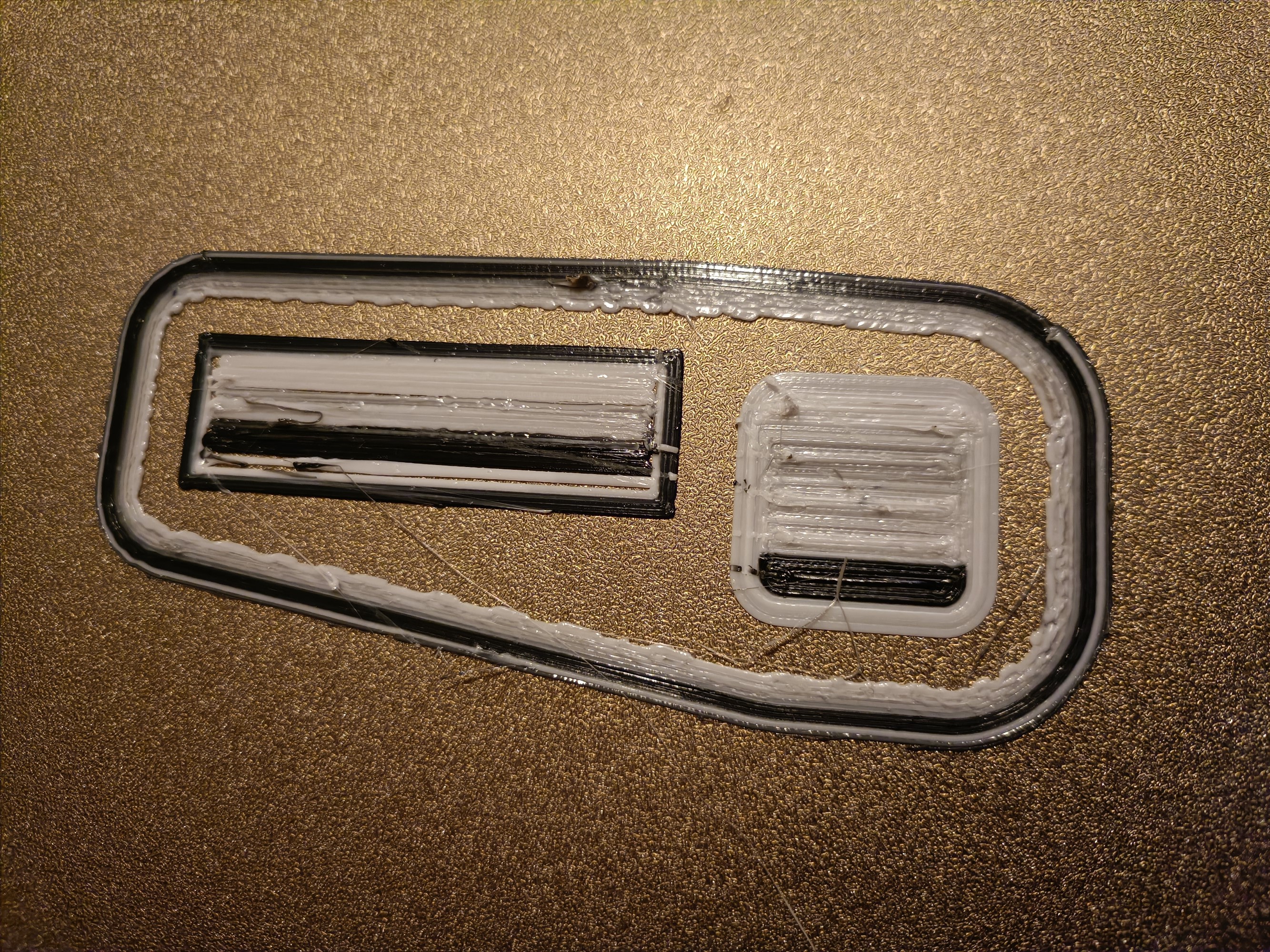
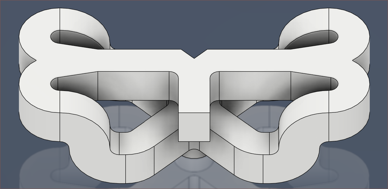
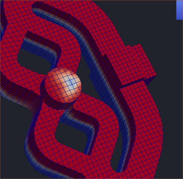
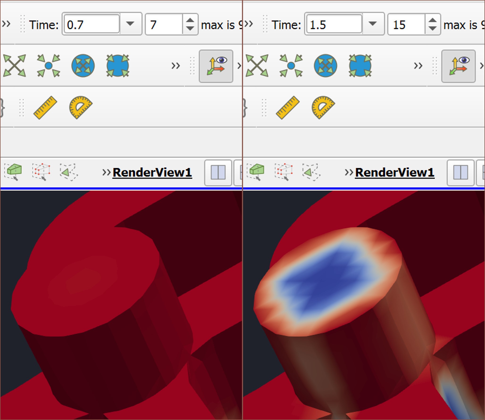
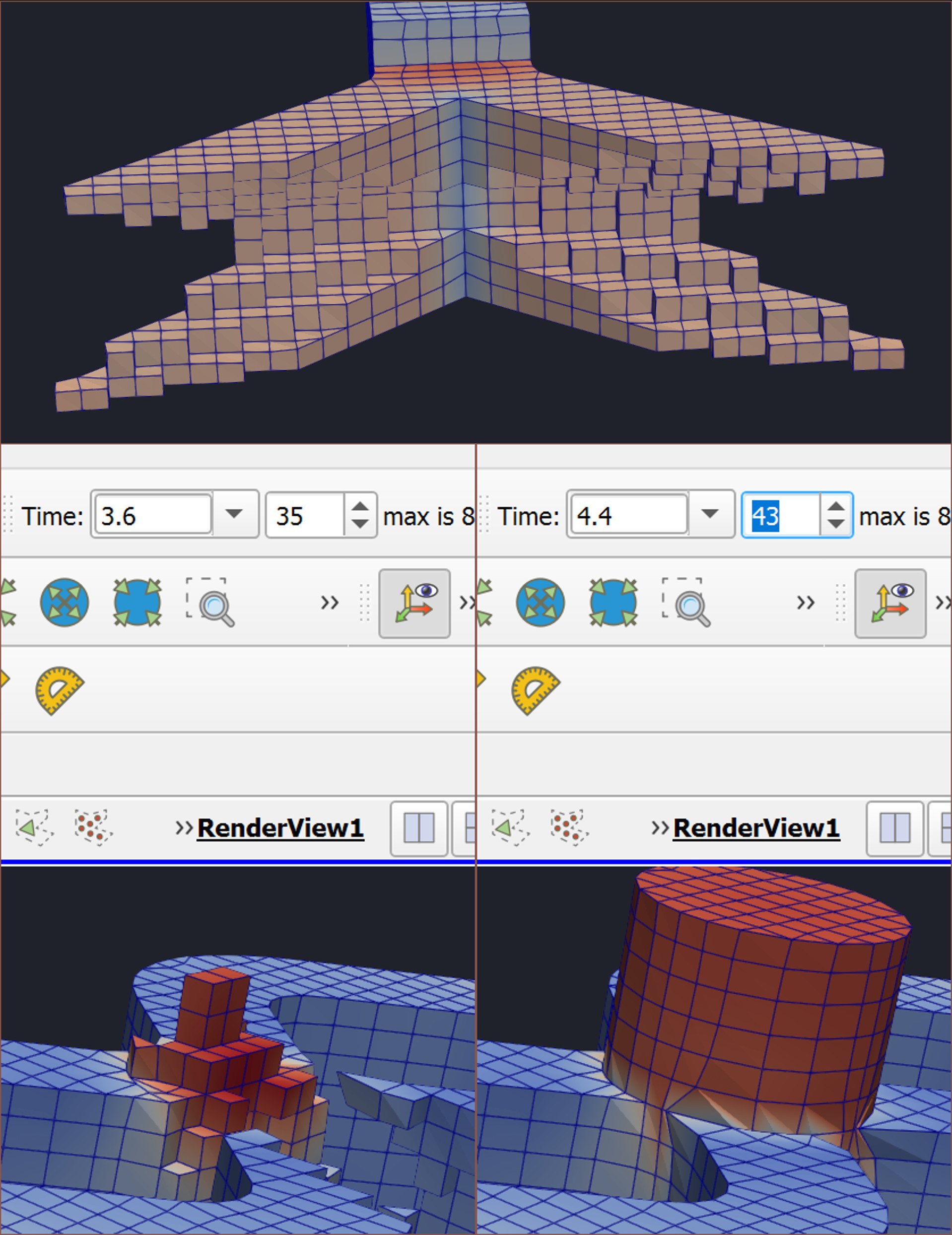
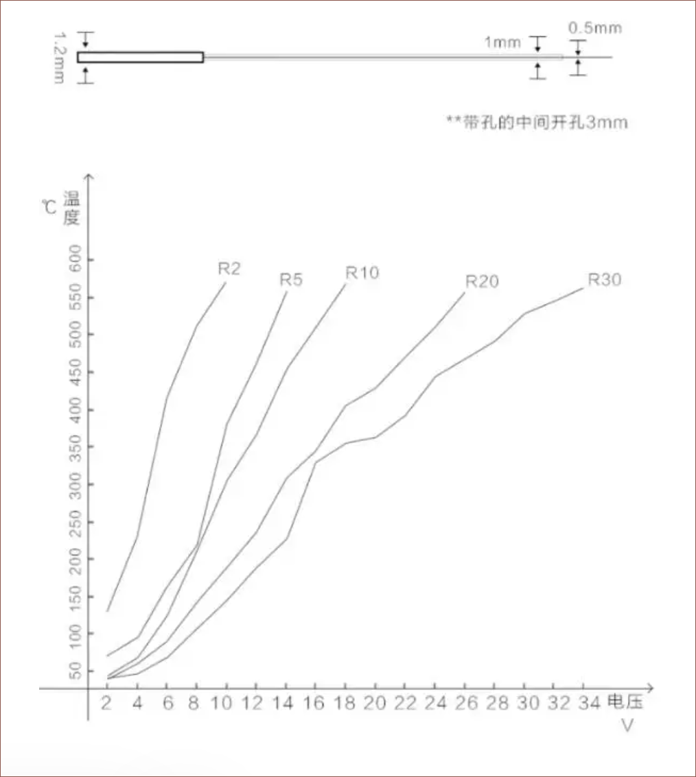
Results
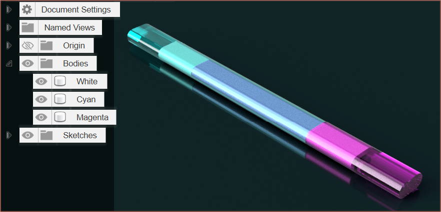
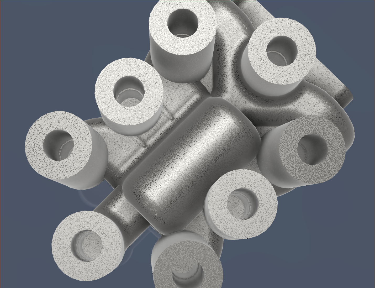
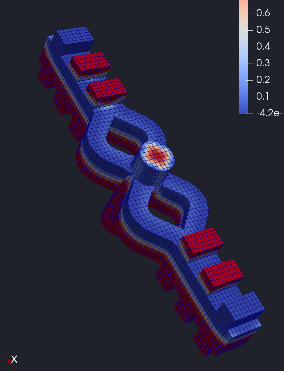
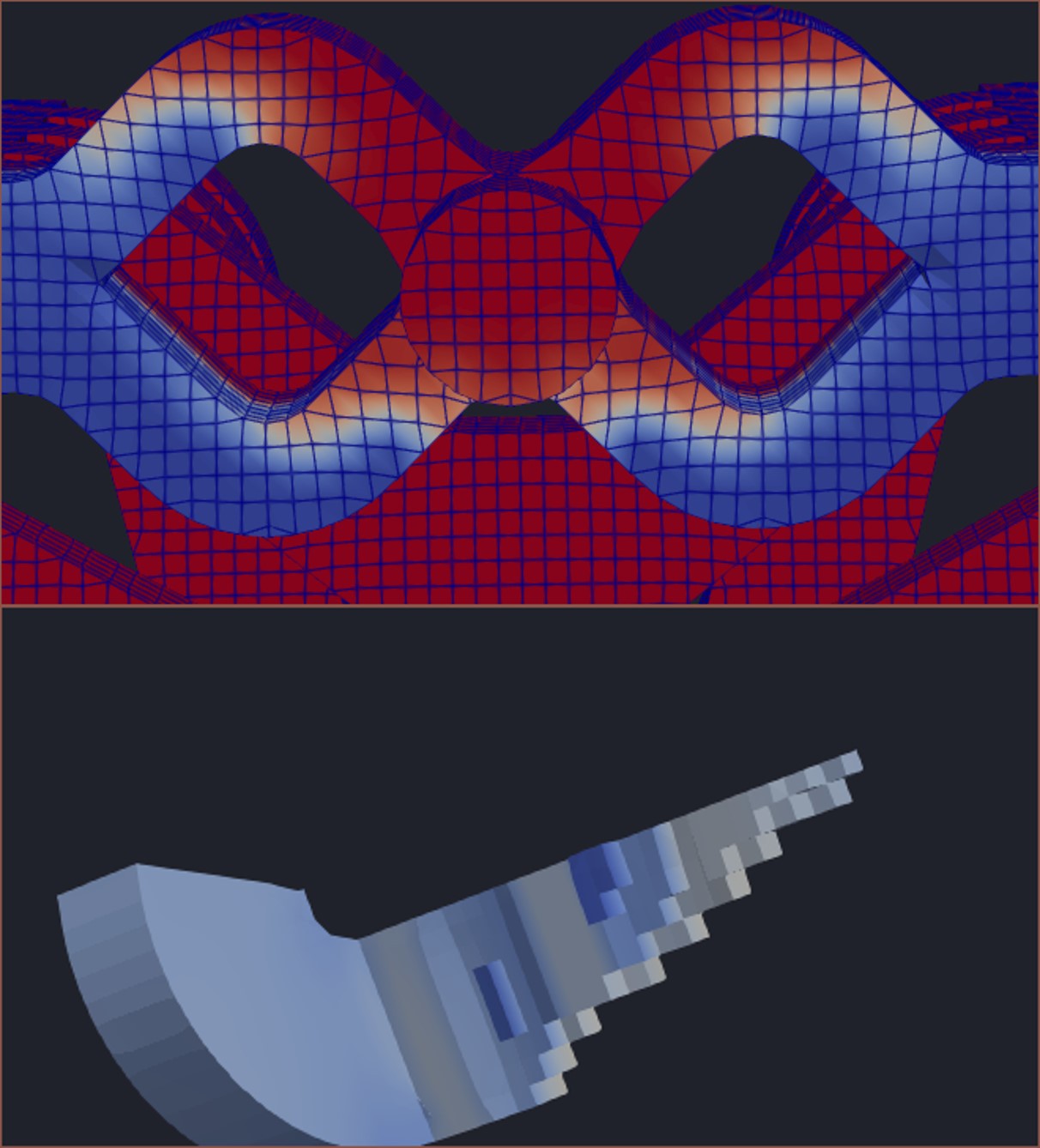
Coaxial8or R3
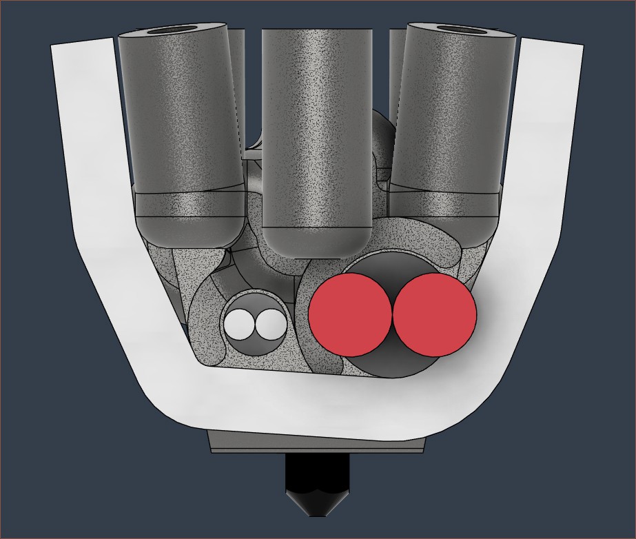
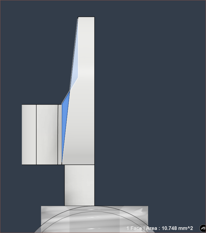
Coaxial8or R2
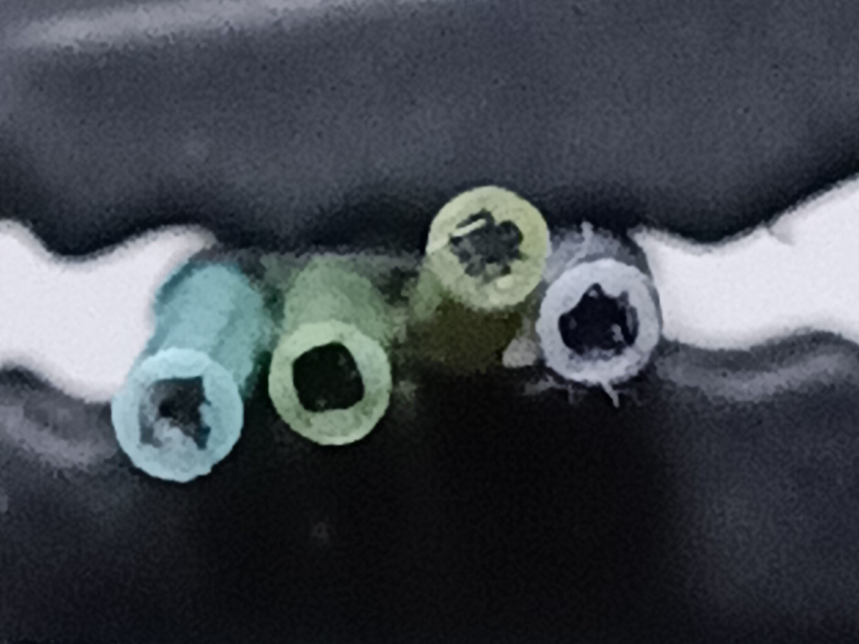
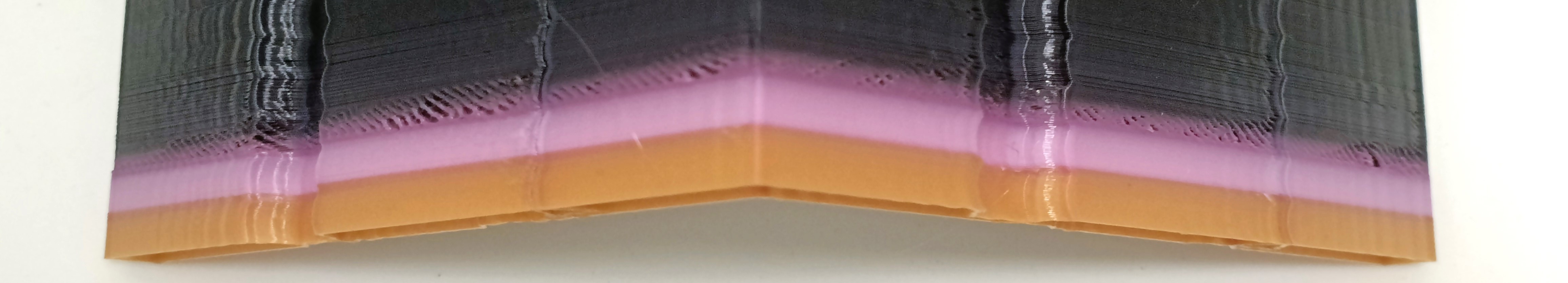
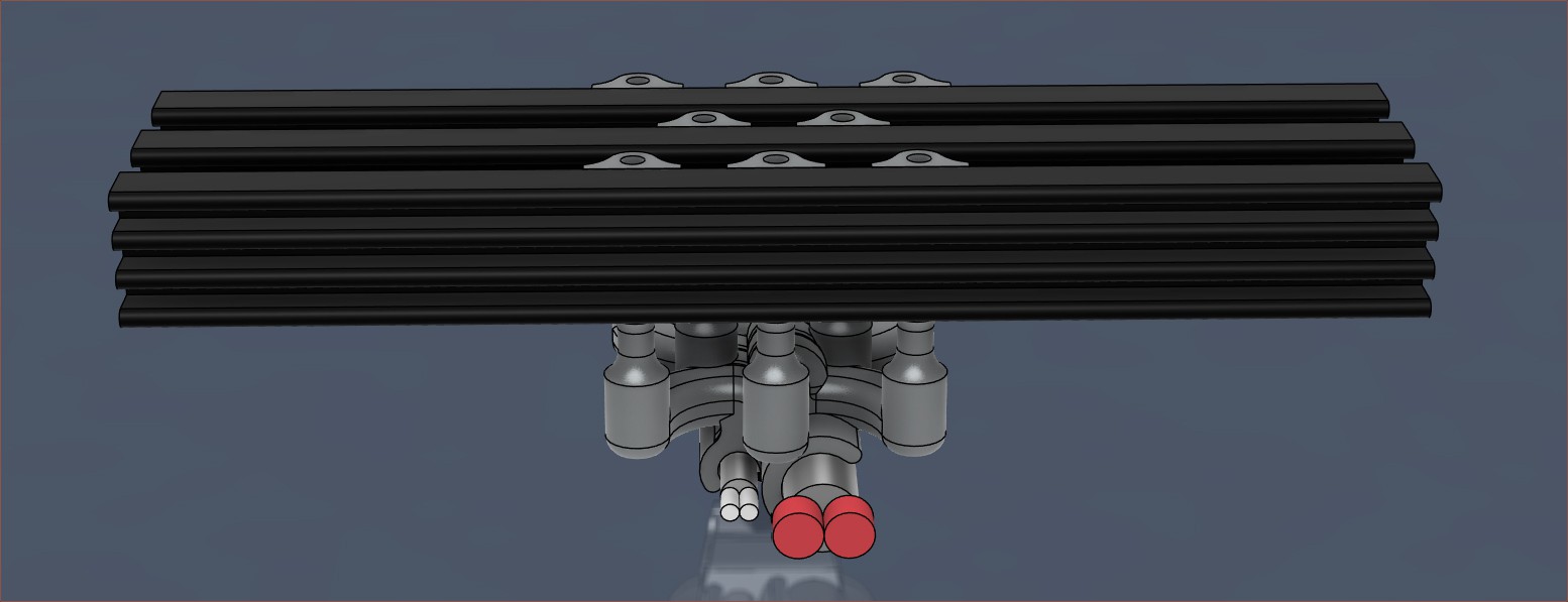
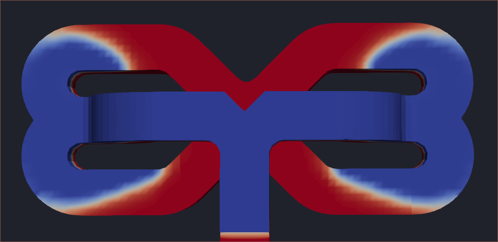
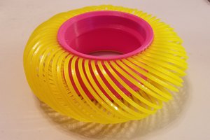
Middle: White around magenta
Bottom: Yellow around magenta
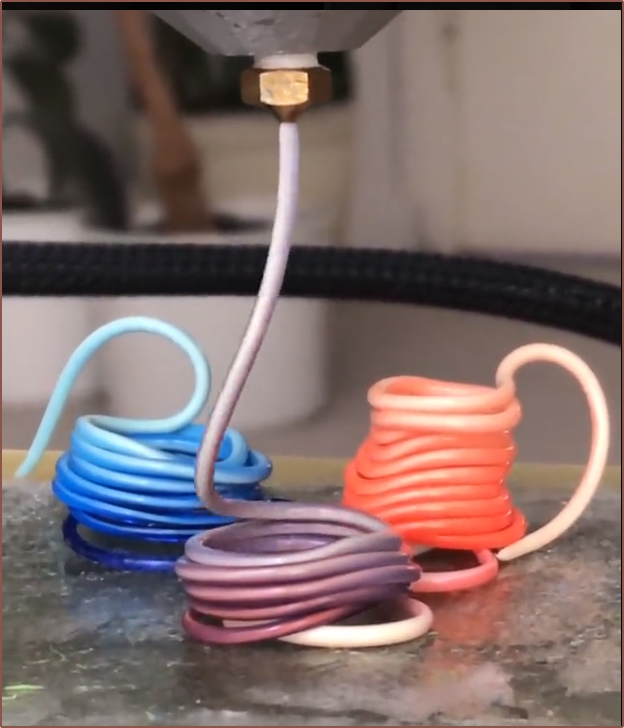
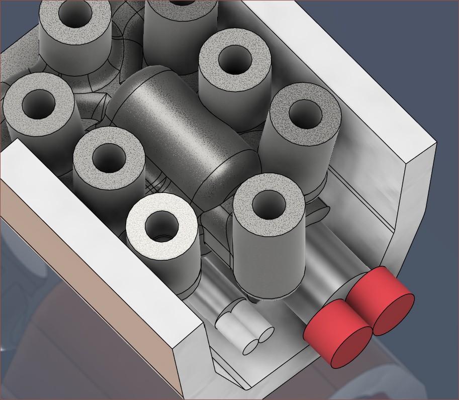
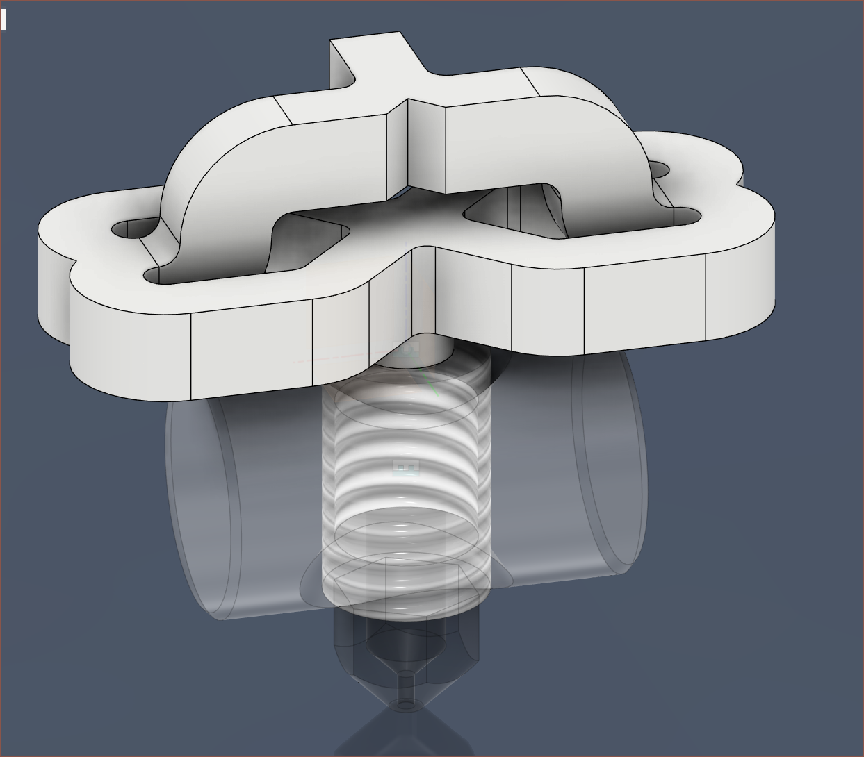
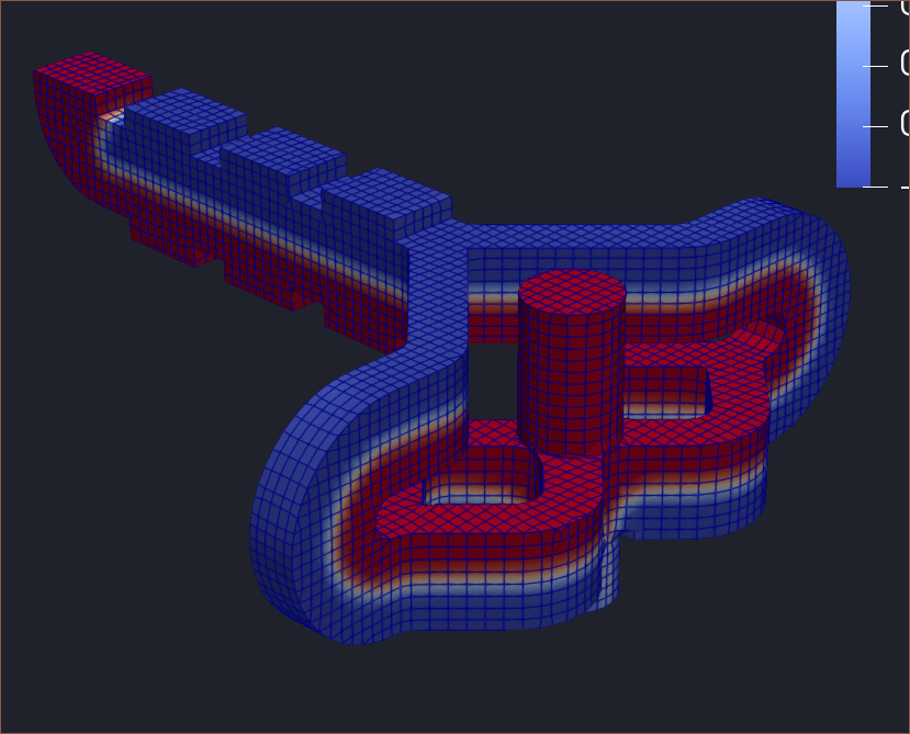
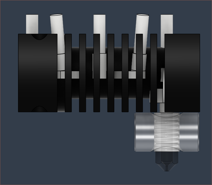
Coaxial8or R0
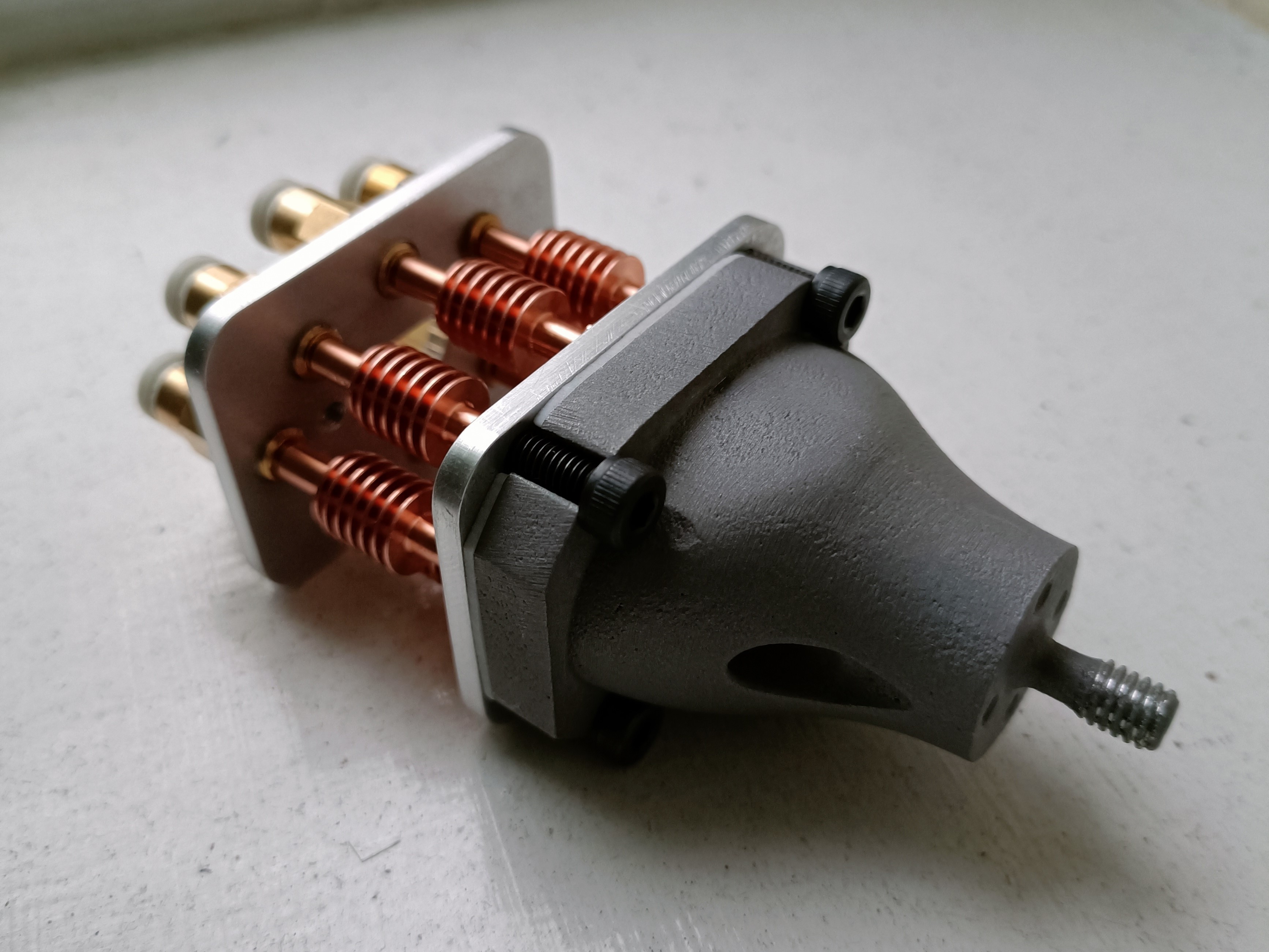
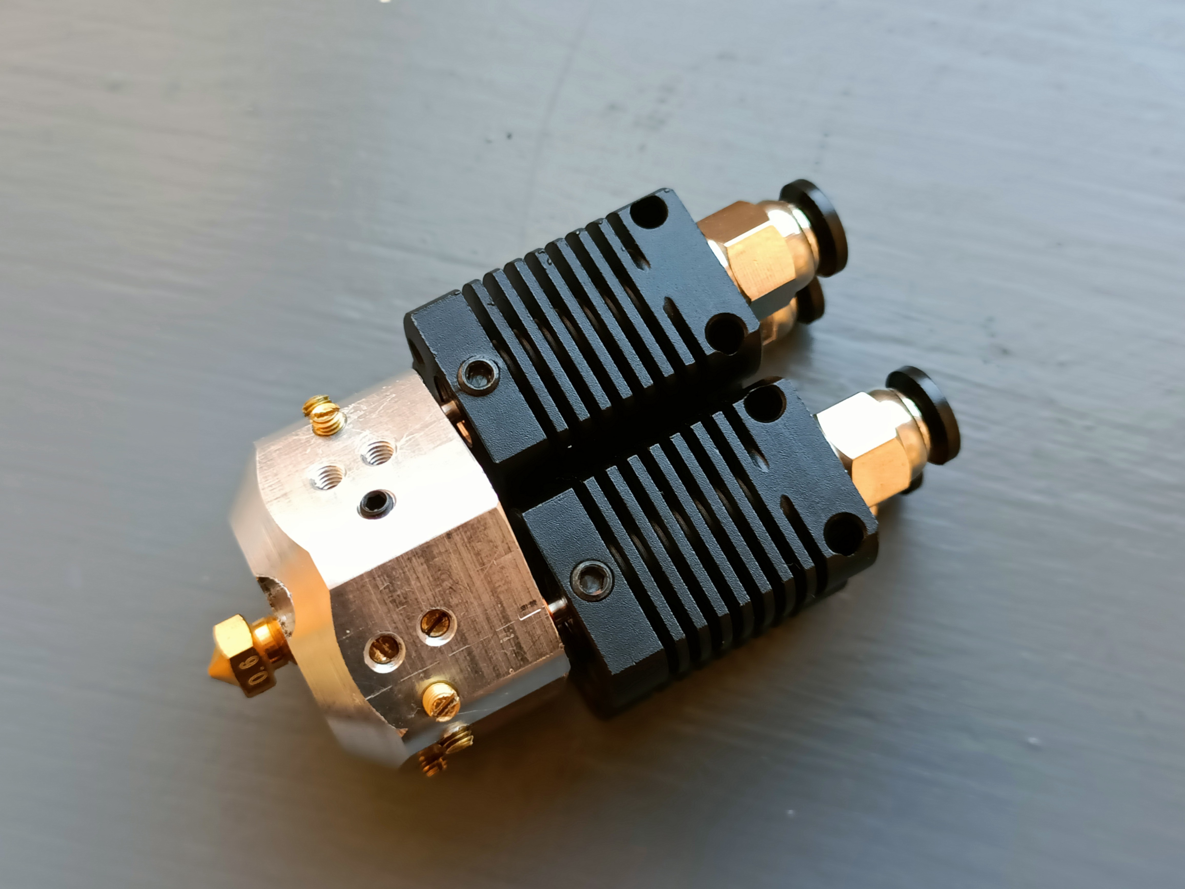
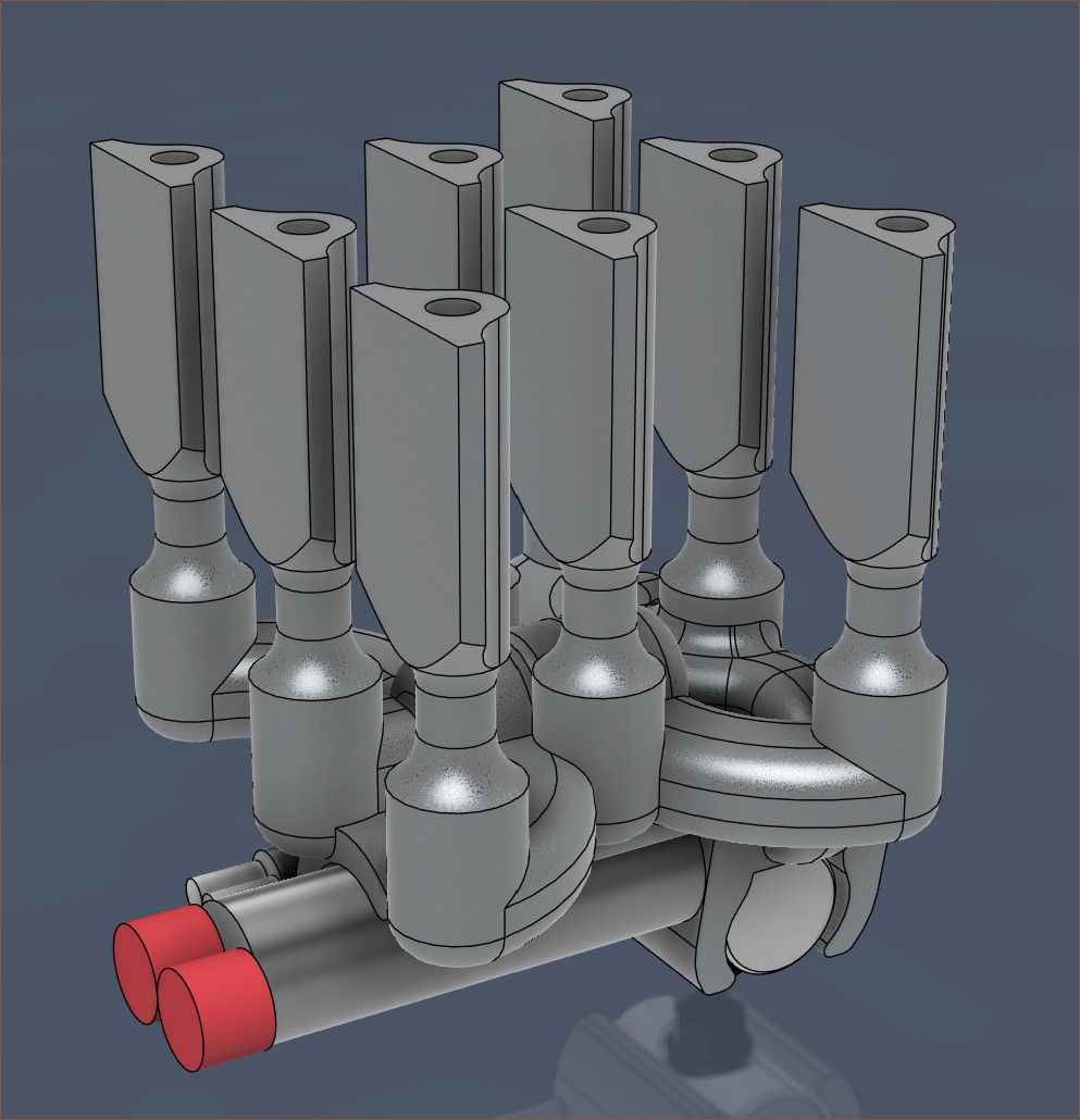
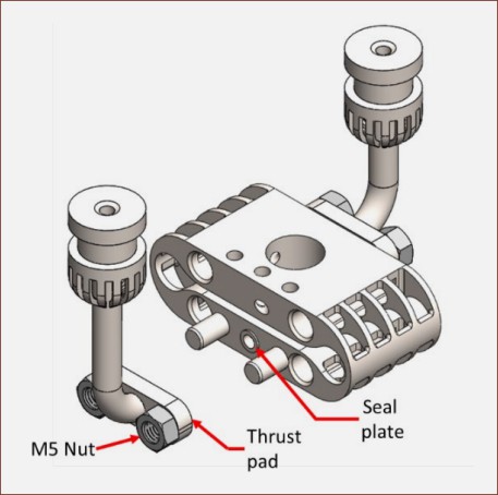
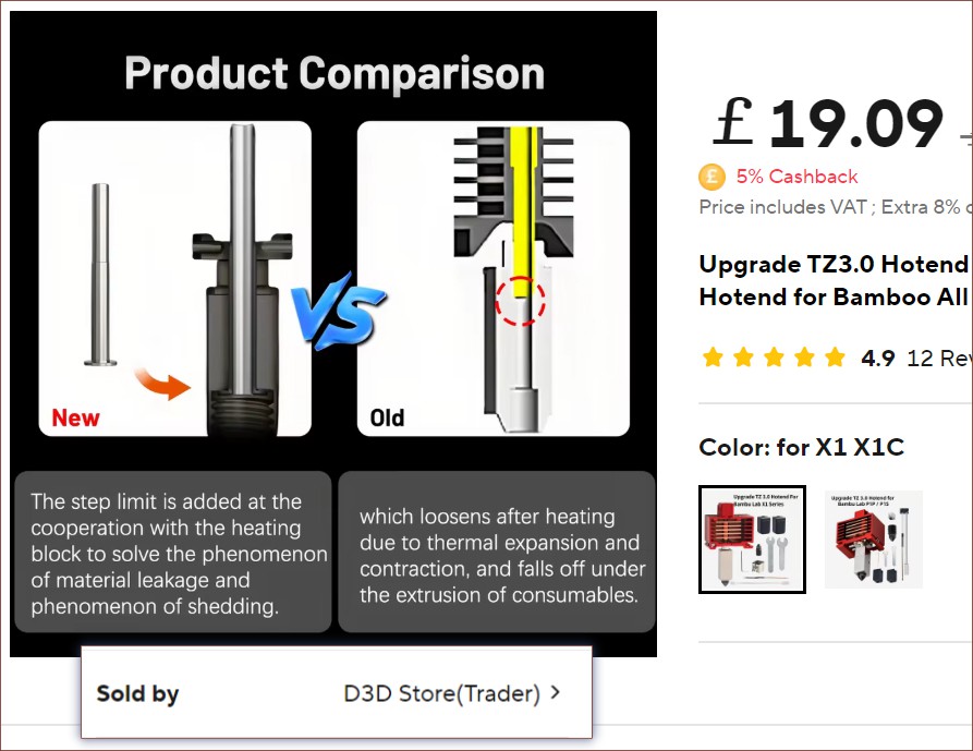
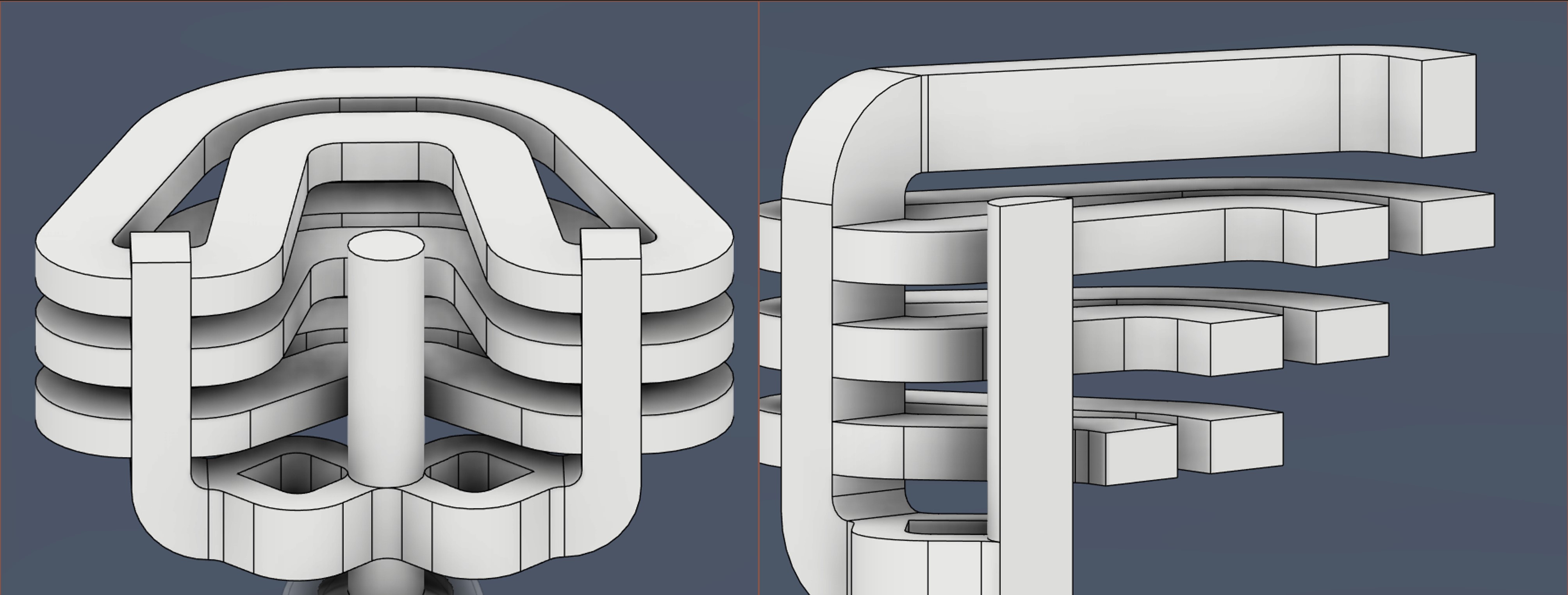
4-in-1-out Coaxial Hotend
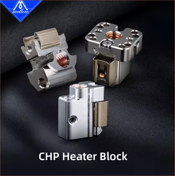
Inspiration and/or examples of working principle
Navigation
The title tag system is explained here, and the table is updated when a change occurs. Notable logs have bold L# text.
Read more »
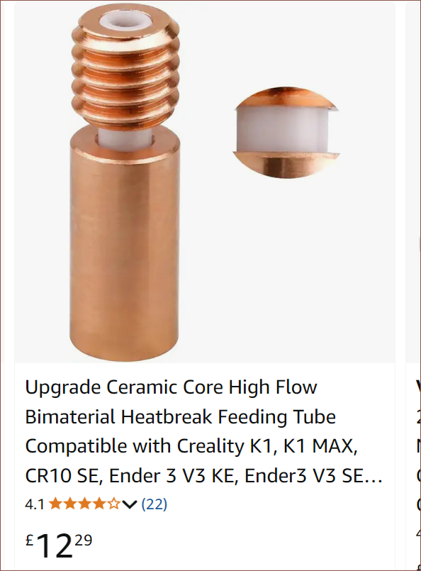
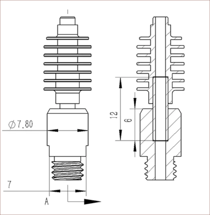
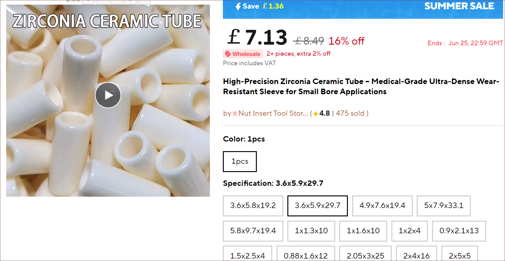


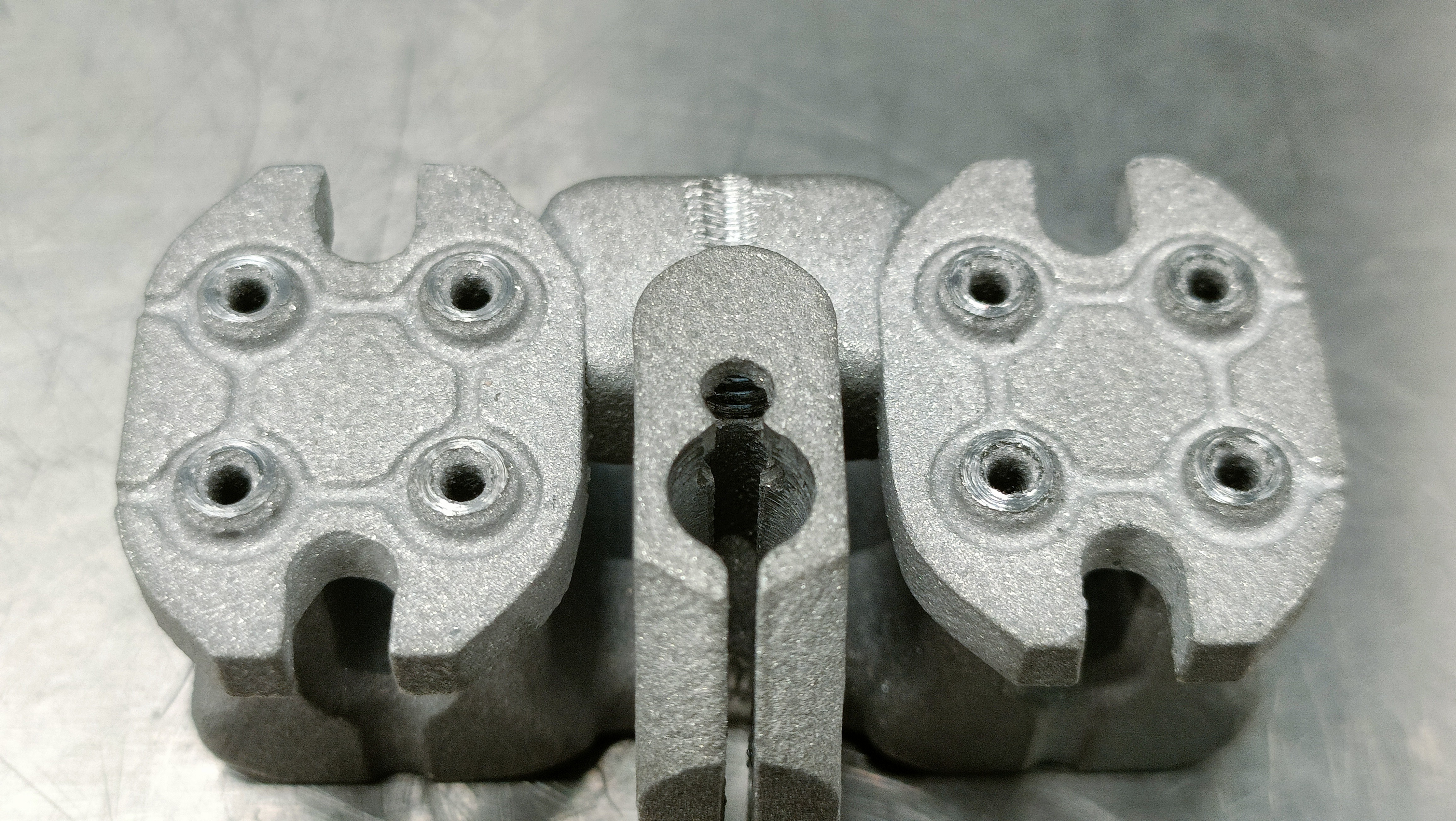
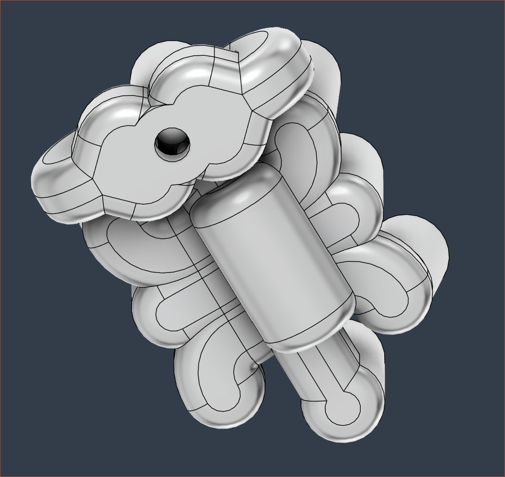
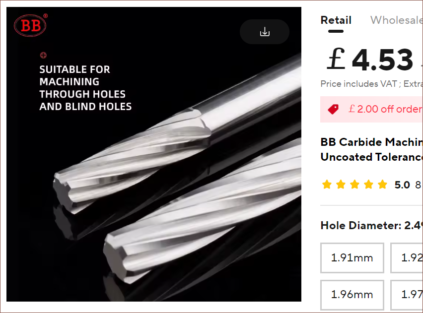
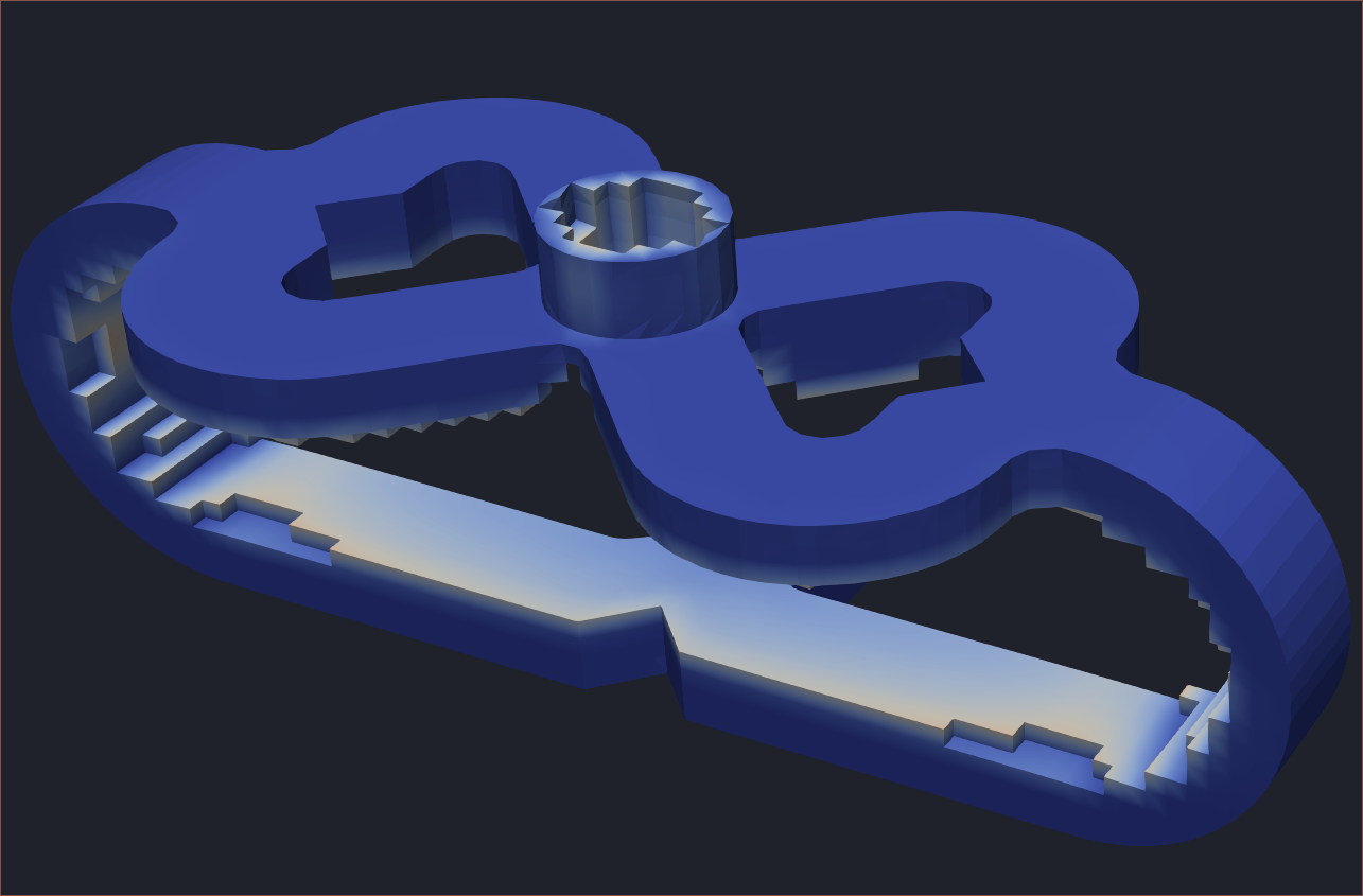
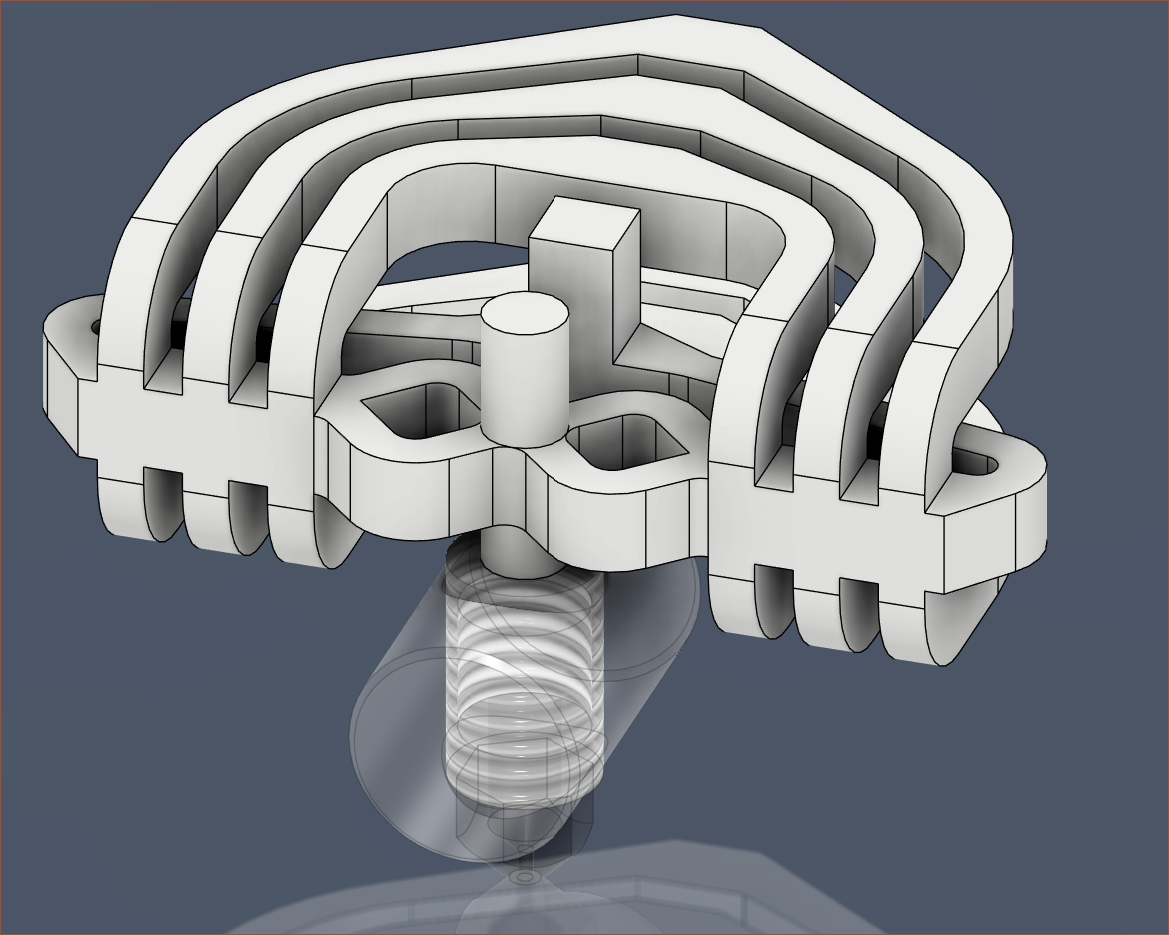
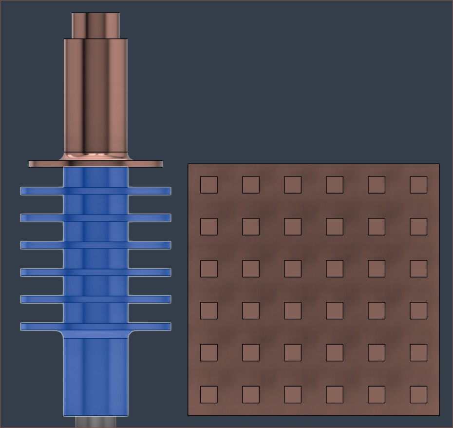
 Currently, I've modelled 1.8mm ID 2.8mm OD tubes to try and balance powder removal, ease of drilling and lack of heat conduction.
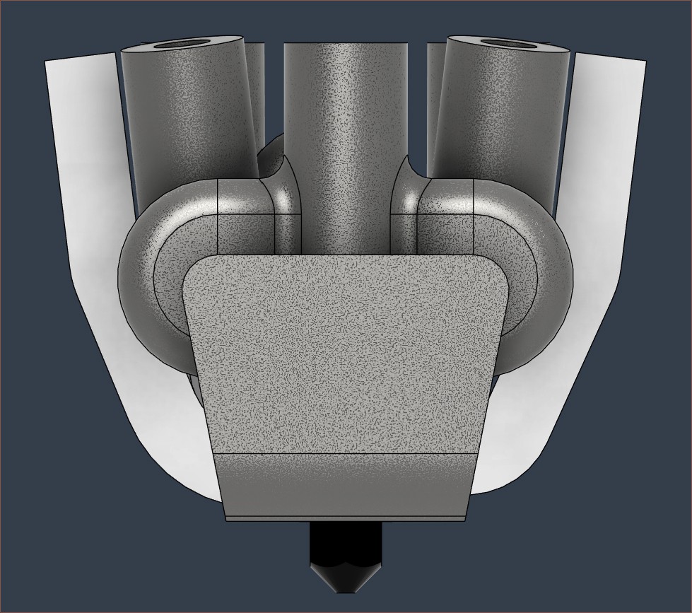 I'm not sure how far I'll get before all the additional manufacturing complexity nudges me over the edge to essentially say "Well, it was a good run, but that


 MasterOfNull
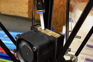
 Tim Wilkinson
I have been following this project for months, and it's my go to morning reading when I clock into work, haha