Close
0%
0%

Coaxial8or [gd0144]

Full-colour FFF? Multi-materials with unparalleled interlayer bond strength? Abrasives without abrasion?

Similar projects worth following
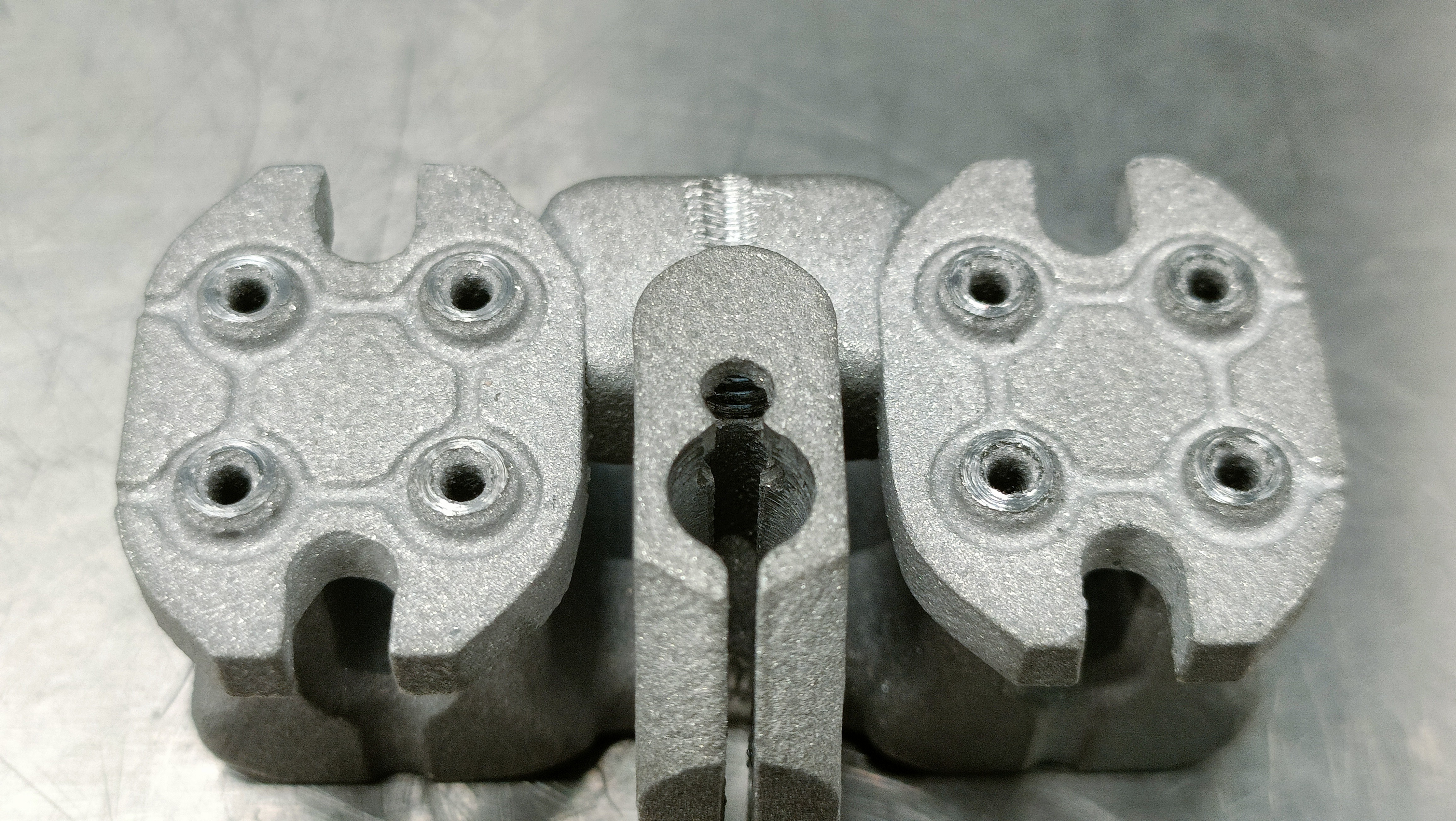
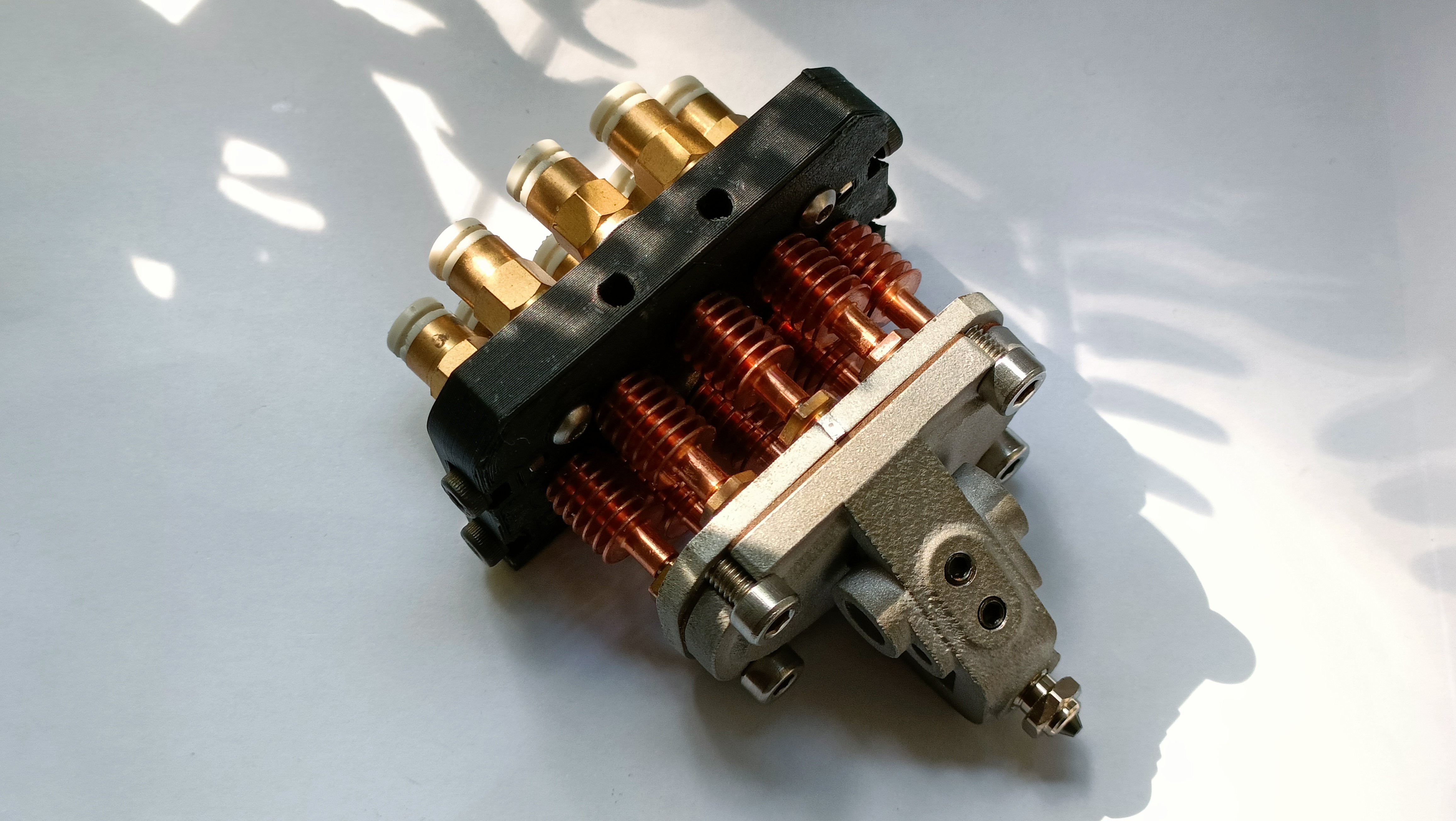
The Coaxial8or (c8or for short) is a heatblock for my CR600S (a modified CR-10) that aims to allow me to bulk-buy 6 filament colours but print in 600. Any feature implemented afterwards is a bonus, such as printing abrasives with a brass hotend or different materials that usually wouldn't bond together.

Results

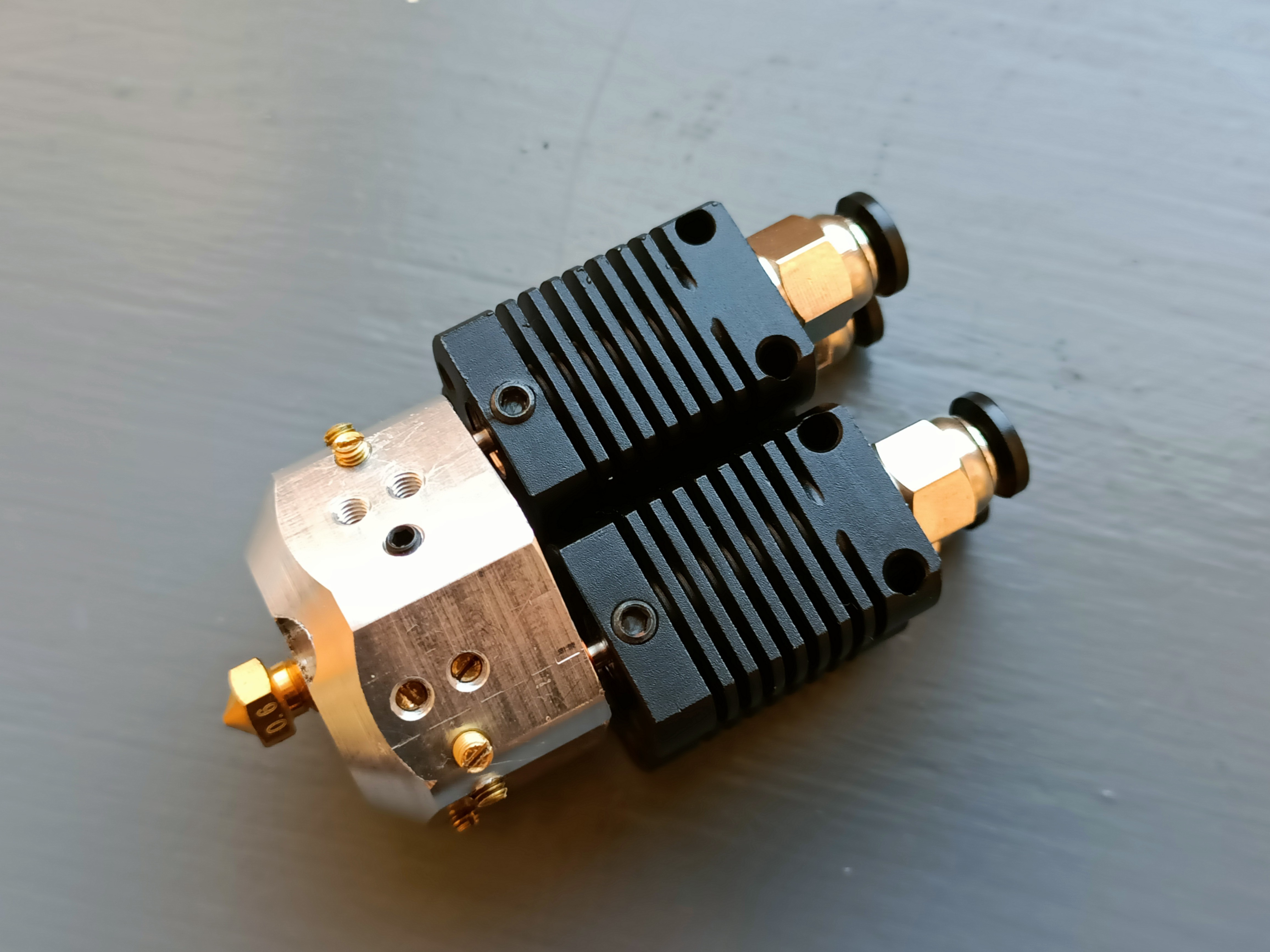
Coaxial8or R2

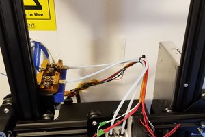
Revision 2 with nozzle and holder installed.
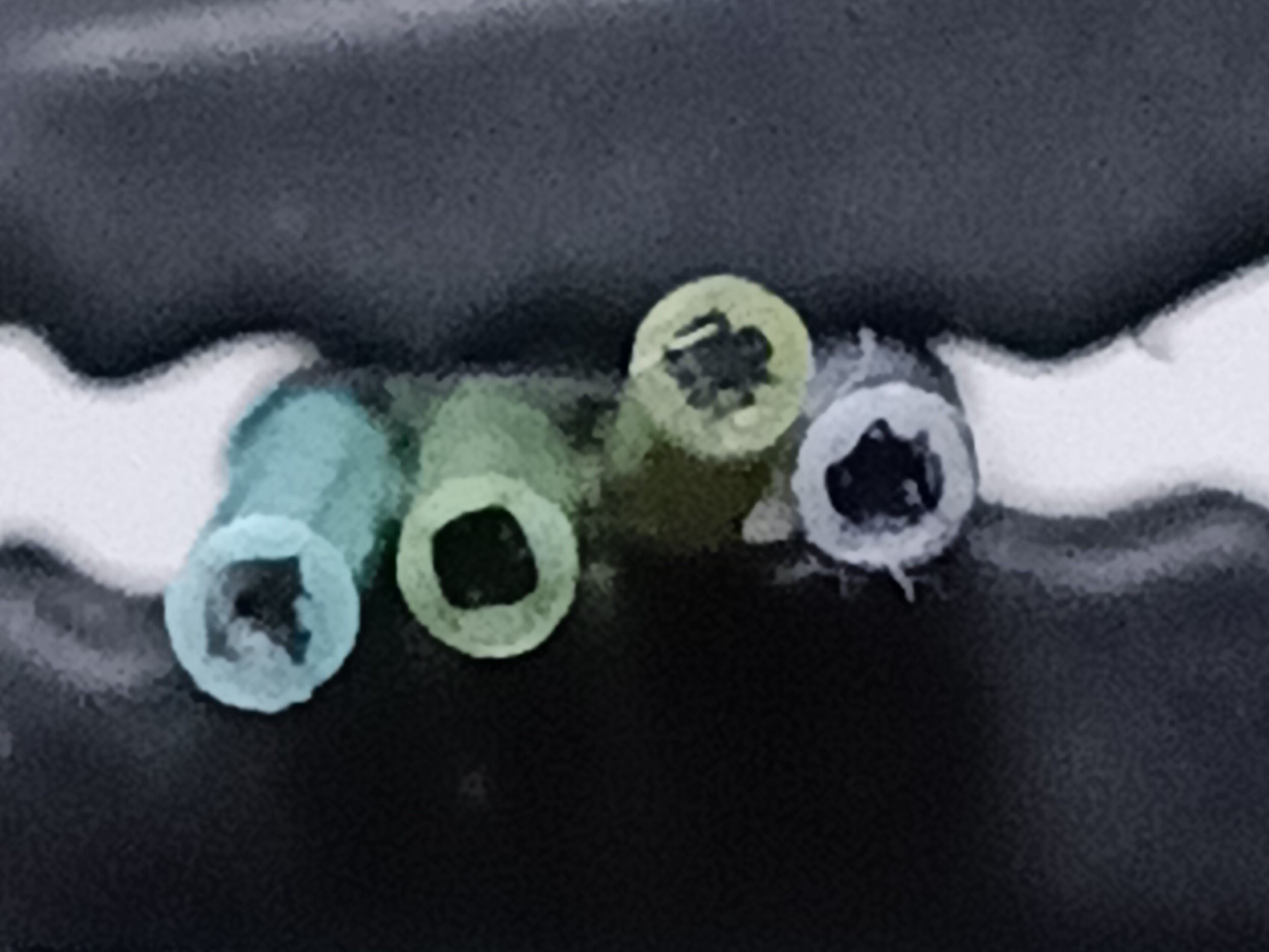
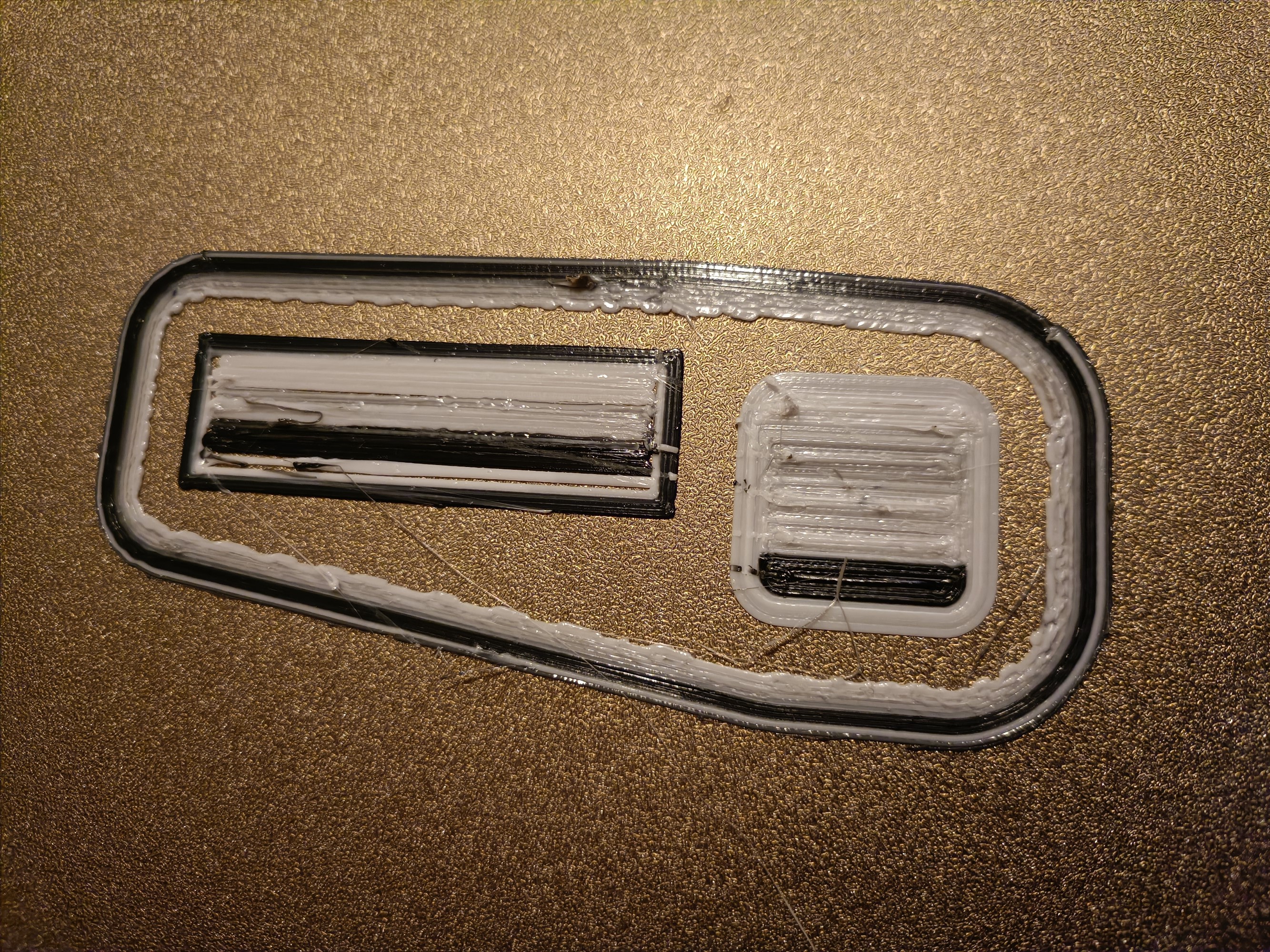
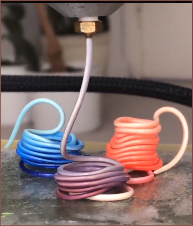
Extrusion from 1.2mm nozzle
White around black PETG

Top: Magenta around black
Middle: White around magenta
Bottom: Yellow around magenta

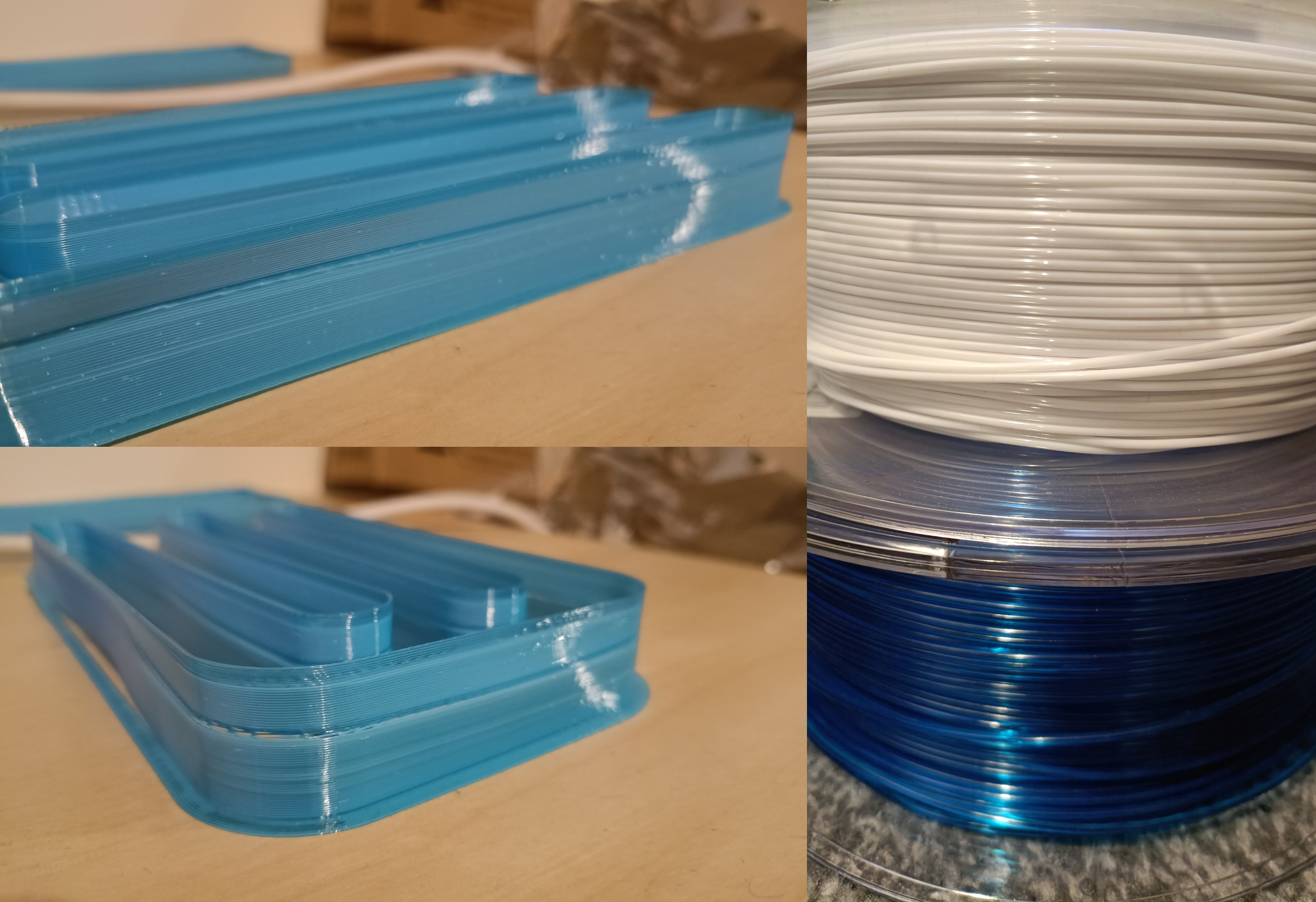
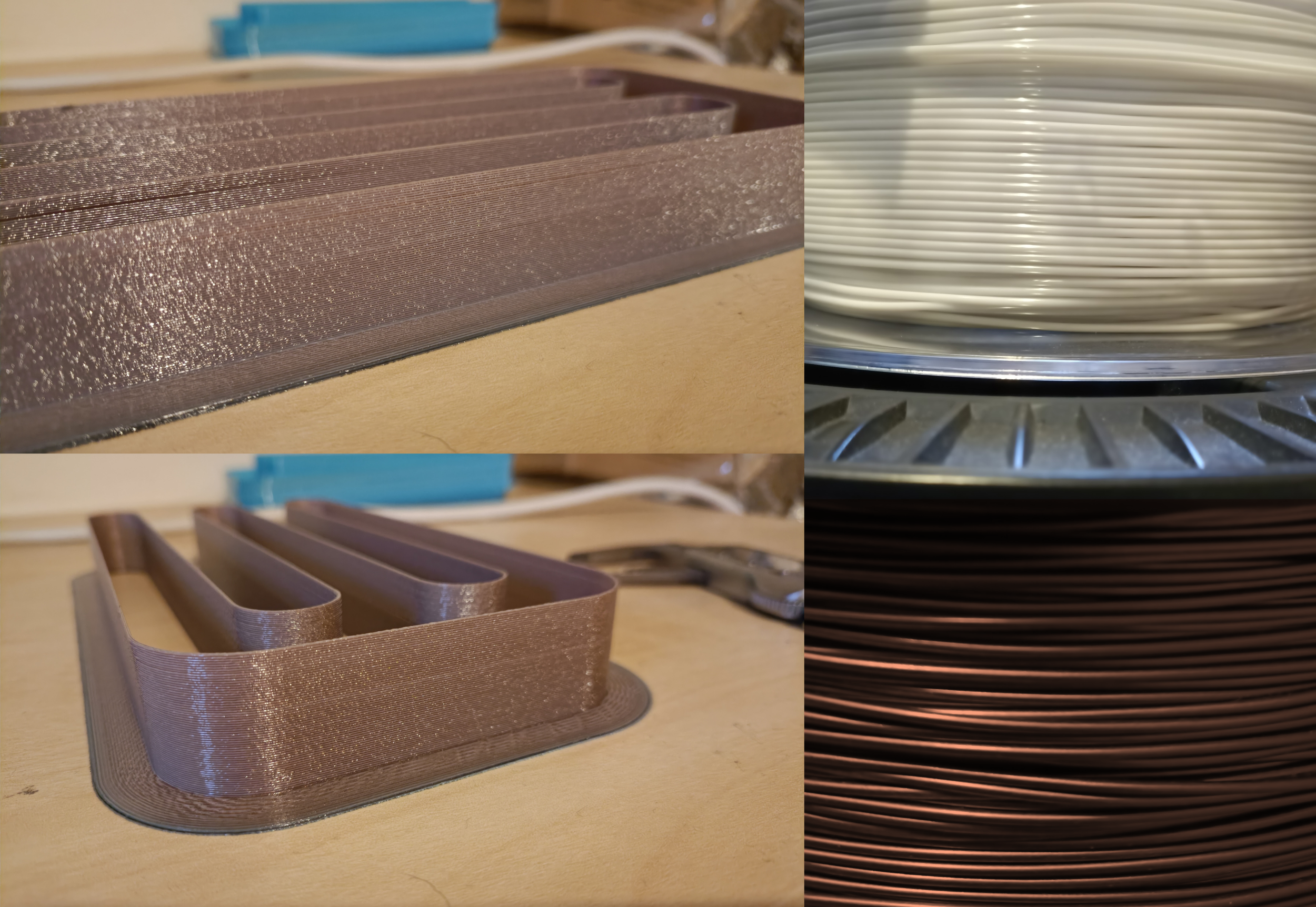
Coaxial8or R0
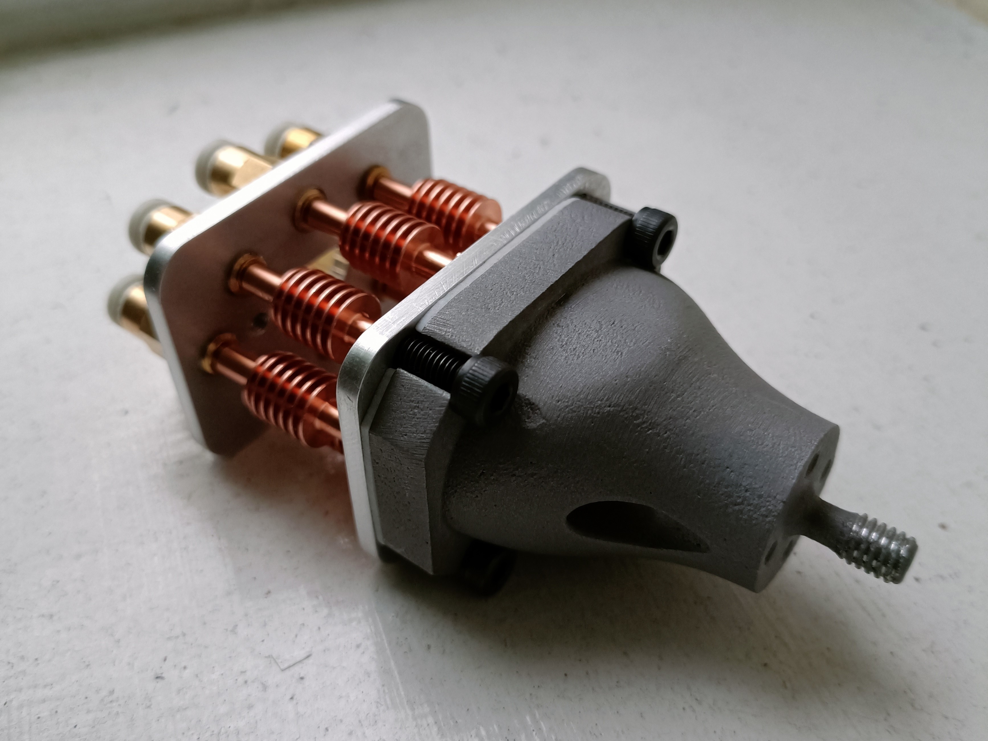
Revision 0 without CHC Pro or holder installed
Produces colours with one side slightly darker than the other:
Transparent blue around white
White around copper

4-in-1-out Coaxial Hotend

I suspect that E-steps was twice as large as they should be.

Inspiration and/or examples of working principle
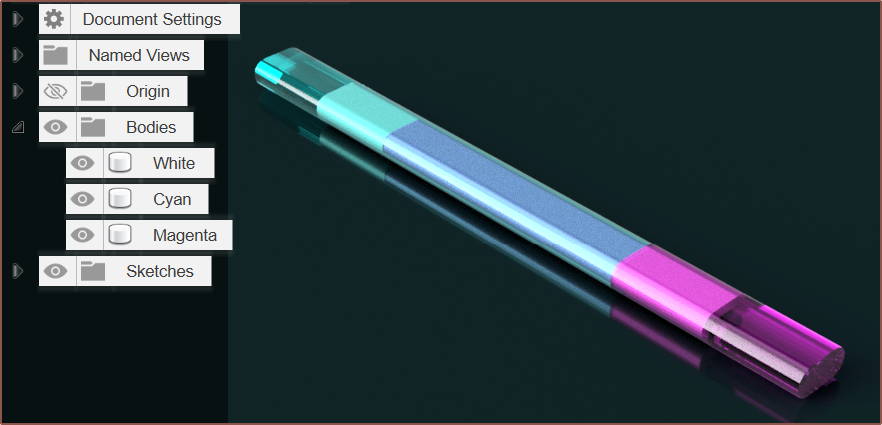
Render simulation of Cyan filament; Cyan coating of White filament; Cyan coating of Magenta coating of White filament; Magenta coating of White filament and finally Magenta filament.
Image source: https://twitter.com/i/status/1648662200544907267

Navigation

The title tag system is explained here, and the table is updated when a change occurs. Notable logs have bold L# text.

L1
[M][T] Initial design and fabrication optimization
L2
[M][T] 5 inputs were possible?!
L3
[T] 4 material + tube?
L4
[M] Center grub insert
L5
[M] Smallest possible size?
- Also possible prior art found
L6
[M] Fabrication Changes
L7
[M] Hotend digitally assembled
L8
[M] Starting on the cover
L9
[R] PCBWay still can't manufacture?
L10
[M] Metal 3D print edition
L11
[M] Asking PCBWay for a brass insert
L12
[M][R] Preparation for Uni round 2
L13
[T] Threads and feedback
L14
[M] Cooling ducts
L15
[M] Carriage Mount
L16
[P] 6028 Fans
L17
[P] All other components
L18
[P] Successful Fabrication and Assembly
L19
[T] Sealing with 2mm ball bearings?
L20
[X] No immediate leaks!
L21
[X] Looking at the state of the grub screws.
L22
[M] M4 Grub + 2mm Ball Edition
L23
[T] An Insert Like The Positron Hotend?
L24
[A] Mystery CNC Price Hike
L25
[T] Hotend hypotheticals: Off-centered inlet approach?
L26
[P][A] Outer Cover and leak detected
L27
[M] Visible indication of full grub tightness
L28
[M][T] Internally groove the heatblock-heatbreak mating surface?
L29
[M] Centrifugal-inlet design with expanding ball plugs
L30
[T][R] Dual heater zones?
L31
[M] 8 in 1 out hotend
L32
[M] Added components to 8 in 1 out hotend
L33
[T] Filament order and issue prevention strategy
L34
[A][B] PCBWay CNC fabrication costs USD$257 - $334
L35
[R] Bowden couplings, collets and compression fittings
L36
[T] Print abrasive filament without abrasion?
L37
[M] Heatsink for Unibody Coaxial Hotend
L38
[M] Finished modelling the Unibody 8-in-1-out hotend
L39
[T] Abrasive filament to smooth internal channels?
L40
[M][R] Simulation software and model optimizations  
L41
[M] Thermal comparison between machined and unibody
L42
[T] Next steps
L43
[A] Details page before 11 Jan 2024
L44
[P] Nozzle-block heatbreak fabricated and simulated
L45
[T] Grub screw sleeve?
L46
[A] CNC price keeps increasing
L47
[C] Setting up Marlin Firmware

L48
[M][T] Machined 6-in-1-out not geometrically possible?
- Also talks about 8-in-1-out tweaks
L49
[X][P][T] CR600S setup and first test prints
- Tests 4-in-1-out hotend
- Thoughts on BotObjects 5-in-1-out hotend heatsinks
- Direct drive idea
- Failed due to leaks so only got 2 short prints
L50
[M] Printed Coaxial Hotend with clamp plate
L51
[B][C][M] Preparing shopping cart and Marlin
L52
[M] Slim Cover and Hotend Holder
L53
[M] 2D plate drawings
L54
[T] Directional fan and new filament strategy
L55
[P][M] Plates manufactured
L56
[M] Heatblock design optimisation
- Tip on preventing profile rotation when sweeping in Fusion 360
L57
[A] Heatblock ordered and 1mm PTFE gasket
L58
[T] Potential name: Coaxial8tor
L59
[M][A] Switch to 17HS4023 Nema17?
L60
[M] More ideal extruder mount
L61
[M] Coaxial8or logotype and test model
L62
[R] 42BYGH24S Nema17
L63
[C] Marlin M165 improvements
L64
[M] CR600S+coaxial8or logotype and numbers
L65
[P] Flat files fabricated
L66
[M] Using Fusion's renderer to simulate colours
L67
[P] Coaxial8or aluminium 3D print
- Other parts arrived:
--- DDE (BMG Clone)
--- Nema17
--- BTT EXP MOT
--- TMC2226
--- £6 400W PSU
--- Bowden couplers
L68
[P][A] Clamp face flattened, motors installed and holder attempted
L69
[M][A]...
Read more »

  • [A] Open sourced R3.1 on New Year 2025

    kelvinA01/01/2025 at 17:03 0 comments

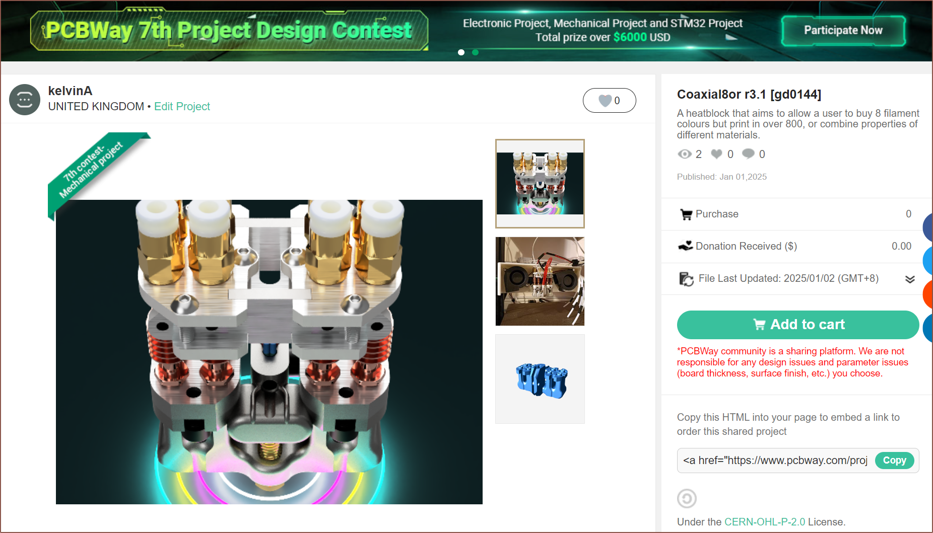
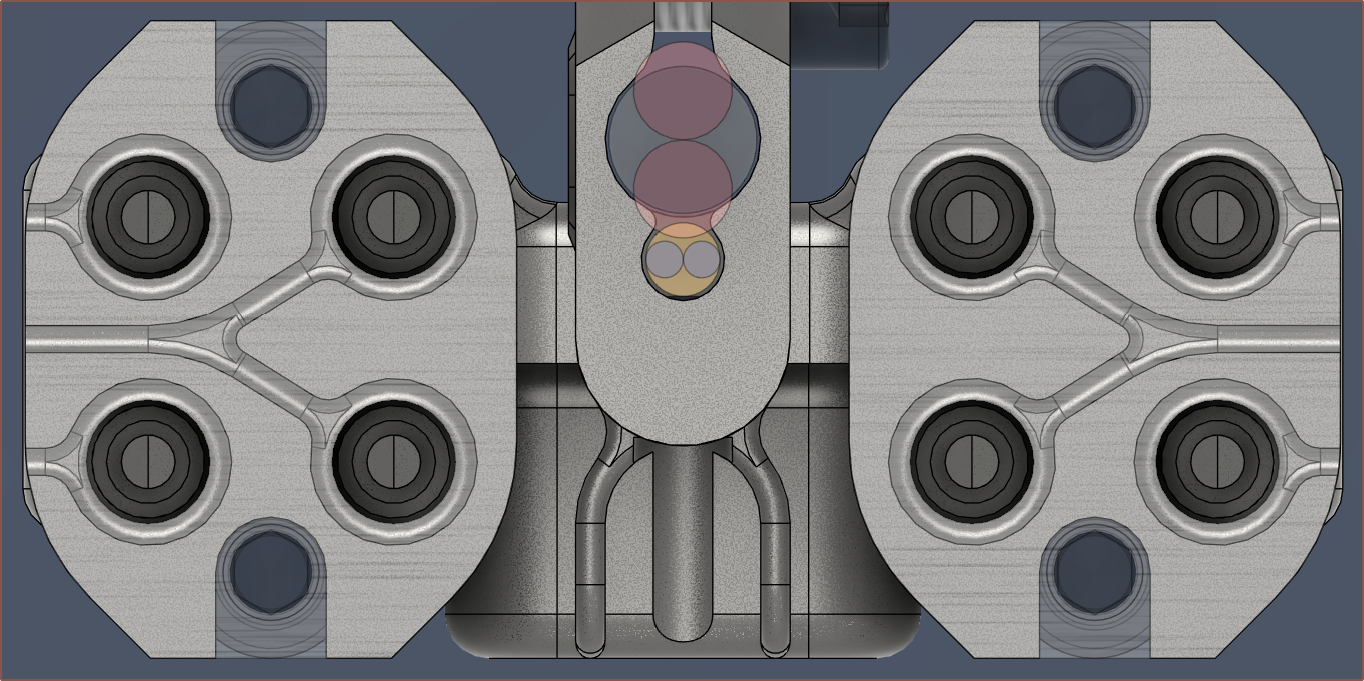
    It may have taken 4 hours, but I've open-sourced the Coaxial8or r3.1 heatblock so that I could participate in PCBWay's 7th Design Contest. 

    R3.1 is essentially R3 with all the post-print alterations, but since I haven't reprinted, it's not the 4th revision. 

    To get things ready to go IPO, I just did a few small tweaks today, such as 

    • finding a better texture
    • filleting the grub shield walls
    • changing the leak paths to 
      • decrease the chance of leaks near the heater cartridge
      • increase the chance that material can be pulled out of the channels when the hotend is heated to around 100C (for PETG)
      • increase the speed at which a leak could be detected

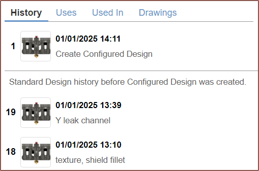
    I also tried my hand at the "configuration" feature that Fusion has had for a few months now:

    Some of the limitations I found was that you can't edit in place, nor do things like change checkboxes (Eg. "Keep Tools" in a combine feature). But now, I can quickly toggle visibility of certain components:
    I've also exported the .step of the hotend holder, partially because the odds that I need to continue revising it are not insignificant. Additionally, it's tangled in the rest of the "Coaxial Hotend" file and trying to "Save a copy" gave me an exploded file:
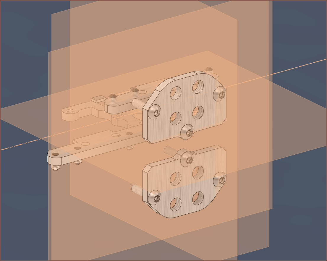
    I've also rendered the latest heatblock and holder:
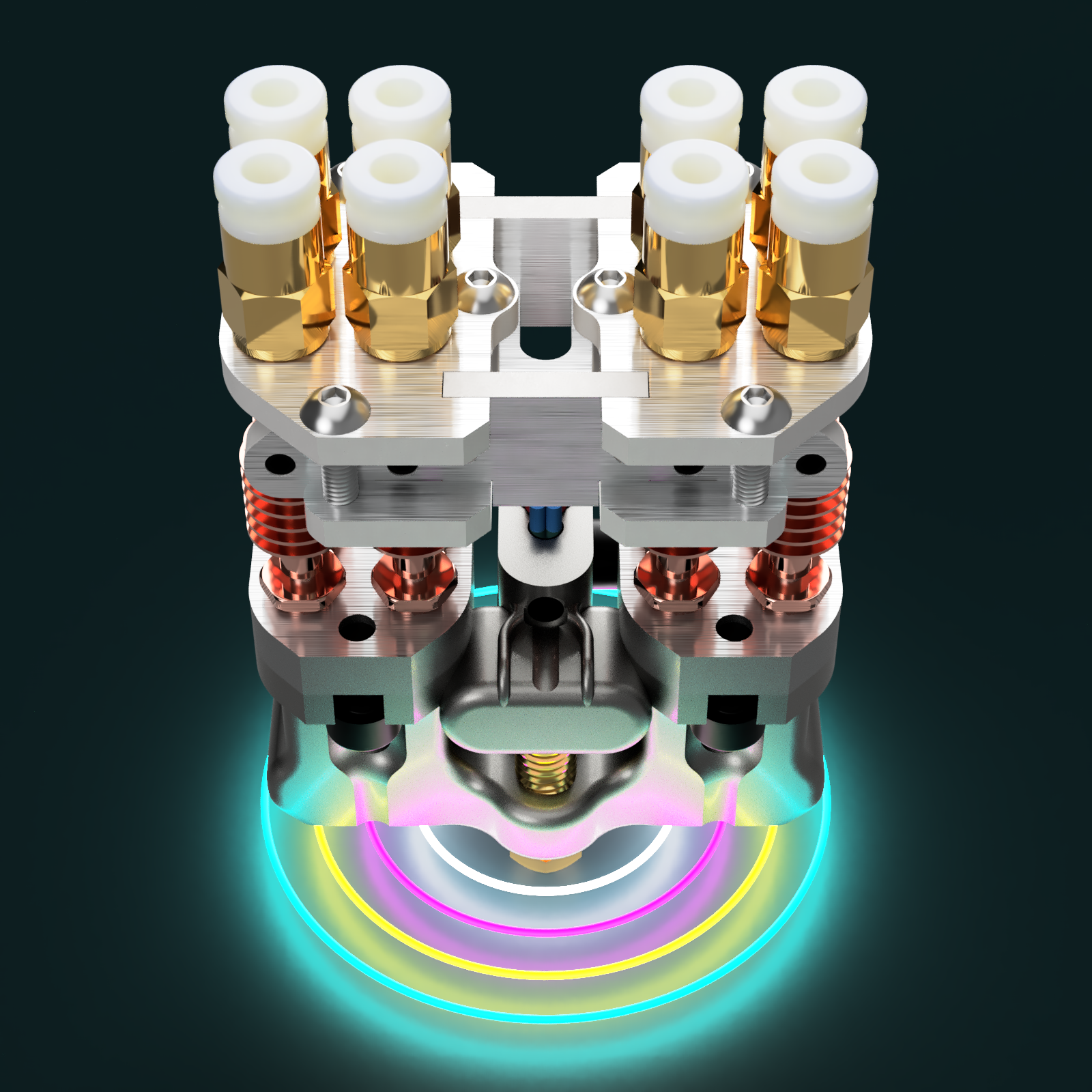
    It kinda reminds me of AI-generated images by how you can see the start but not the end of the cartridge wires.

    I read the Open-Source Hardware FAQ and confirmed my choice to use the CERN hardware license. I'm not sure if it matters much compared to Creative Commons in the grand scheme of things.

  • [A] Compressed HSVA workflow

    kelvinA12/28/2024 at 14:21 0 comments

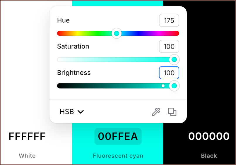
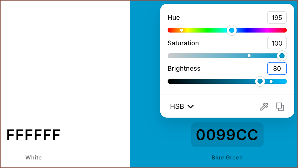
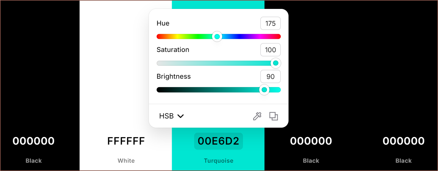
    I'm currently getting great results with the compressed HSVA colour system workflow using coolors.co:

    The above is the Mint PETG I have, and my workflow is to:
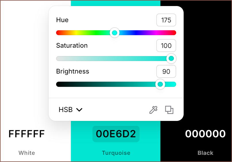
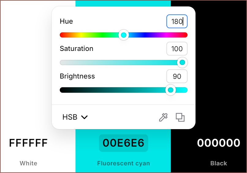
    • Use smartphone flash as a white light source to shine through the filament
      • My reference is:
        • 50% - Max transparency whilst still retaining 100% saturation
        • 100% - Effectively opaque for 1.75mm filament
    • Get an offcut of filament (or 3d print)
    • Place it next to a white reference
      • I'm using my white spacebar
    • Max out saturation and brightness sliders
    • Shine flash on filament sample
    • Move hue to nearest 5 degrees
    • Move brightness to nearest 10 percent
    • Move saturation to nearest 10 percent
      • I find this to be the least confidence-imbuing slider since colours look more similar, particularly at medium-low brightness values

    With this, I can get a confident compressed-HSVA mentioned in this log, but I still move the sliders around by 1 step to make sure I've got the right colour:

    Confident YES:

    Confident NO:
    Confident NO:

    There was no shine-through for the mint, thus the colour for this not-quite-cyan is 35.a9a.

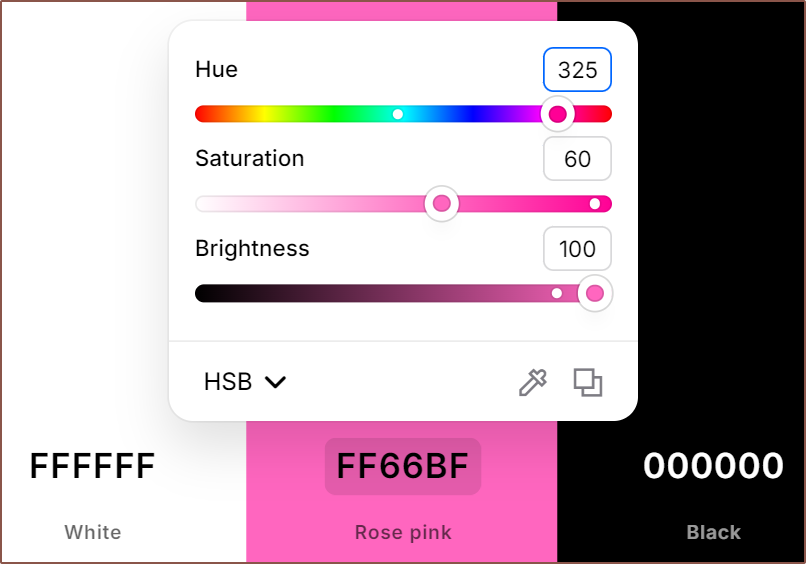
    Surprisingly, my pink is so much further away from the ideal magenta. The hue of the mint is only out by 5 degrees, yet the pink is out 25 degrees and admittedly desaturated:

    It also has a bit of a glow when the filament is lit from behind, so its value could be 70.6a9.

    One possibility for the hue is screen colour reproduction, and I know that pinks have always been questionable on various IPS panels. On my OLED phone, this same colours looks much more vibrant... oversaturated even. On my 9th gen iPad I happen to have, the hue is 315 and other values are unchanged. This is part of the reason for the compressed colour space; there are so many variables that the precise value isn't that meaningful. 

    Considering a substantial amount of people have an unmodified iPad, touted with "TrueTone" technology, I will use it as the hue reference.

  • [A] Opaque filaments create sRGB gradients

    kelvinA12/27/2024 at 12:43 0 comments

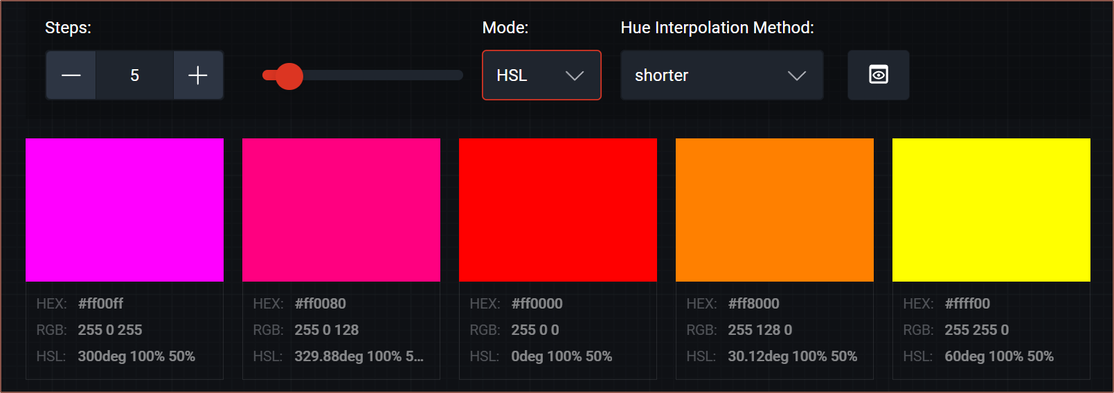
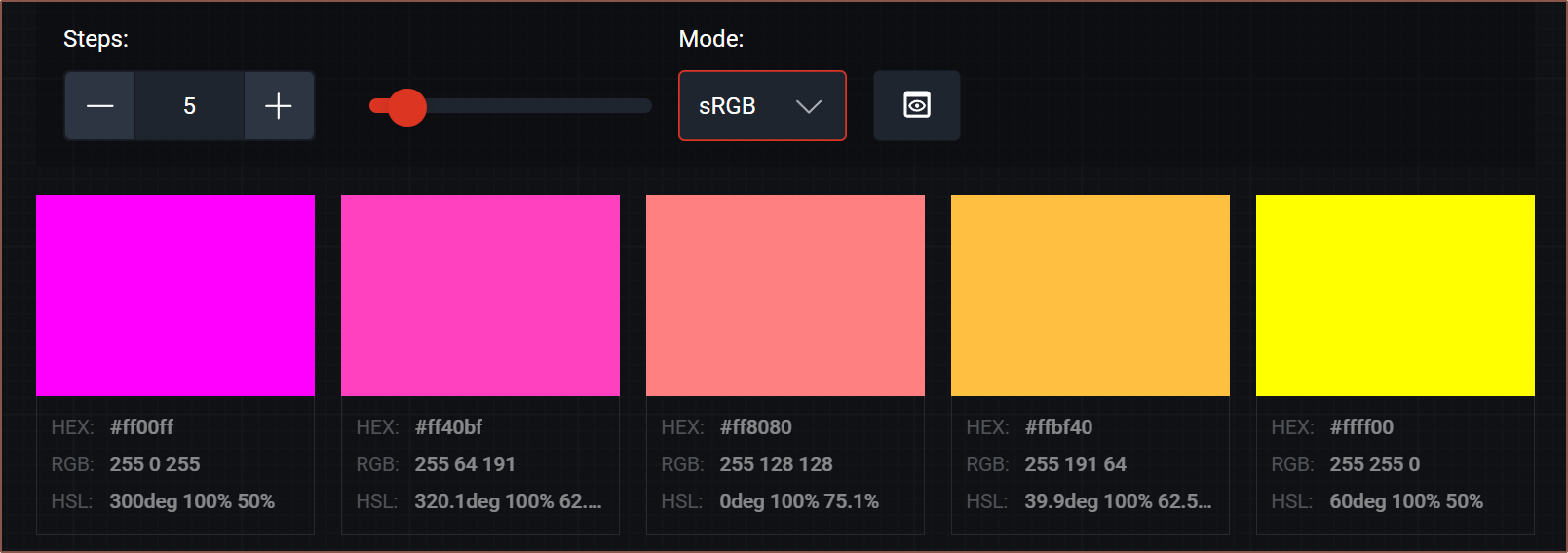
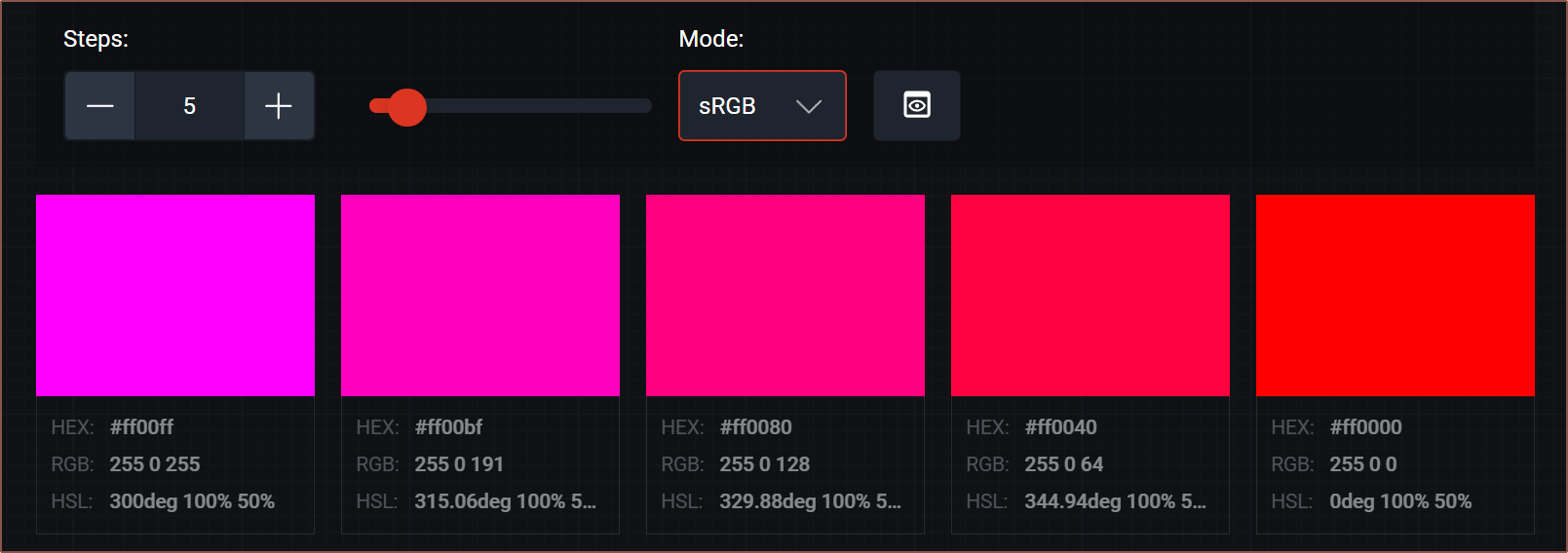
    After looking at the colours I obtained trying to print the gift box, and remembering about the dithering log I wrote, I used this gradient generator to discover the issue:

    Expectation:

    Reality:

    At least I know I certainly found colour-accurate magenta and yellow filament.

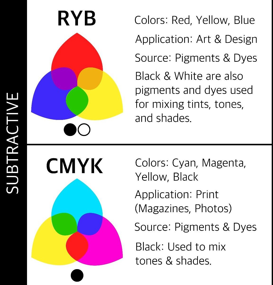
    CMY and RYB

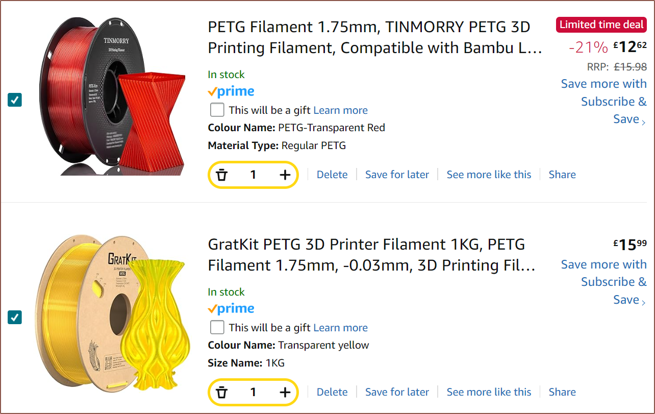
    This explains why Heinz and others before him used transparent materials for colour mixing. The issue is that such filament is even harder to source, particularly for magenta. I've already got YouSu Transparent Blue, which is transparent cyan(ish): 
    Since it's transparent, I could just hold the filament infront of the white and eye^2-dropper with the compressed colour space mentioned in the previous log.
    Yellow seems available, but I've only been able to find Transparent Red:

    This highlights one of the reasons for the Coaxial8or project in the first place. It's one issue if you have to wait days or pay for an entire kilogram of material for a colour, and it's another issue if that colour isn't even commercially available.

    Looking at the below, it sounds like one would still be able to get a decent gamut:

    Source

    Another thought: maybe that's all that is needed? Maybe magenta, the innermost of the 3 hues, can stay opaque while cyan and yellow can tint it. Opacity wouldn't be very stable, however.

    The alternative is dismissing transparency entirely and using 3-bit colour: White, Black, Red, Yellow, Green, Cyan, Blue, Magenta. For FFF 3d printers, transparent filaments are more like a visual effect, similar to matte, marble, silk, sparkle and glow. 

    The sRGB and HSL gradients are identical

  • [E1][X][M] Tried to print a gift for 8 years of CR600s

    kelvinA12/25/2024 at 16:37 0 comments

    On the 25th of December 2016, I got into 3D printing for the first time with a CR-10.

    I woke up on the 24th of December 2024 and I had an idea: Since the Coaxial8or kinda works and tomorrow marks 8 years since I first printed on "the CR-10 now known as the CR600S", I should try and print a two tone gift box.

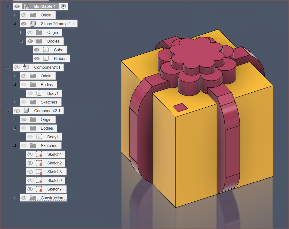
    Designing the box was simple

    Obviously, to celebrate years worth of calibration cubes, I modelled a ribbon-wrapped 20mm cube with an 8-sided flower-bow on top. I also added a little pillar so that I could mark orientation (because this is still a calibration cube at the end of the day). I joined the pillar with a very narrow (0.001mm) extrusion so that it and the ribbon counts as a single body:
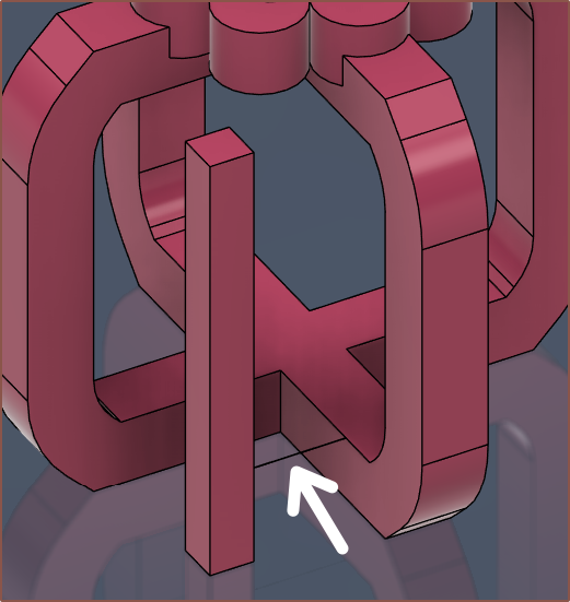
    It should also be of no surprise that the ribbon has filleted chamfers.
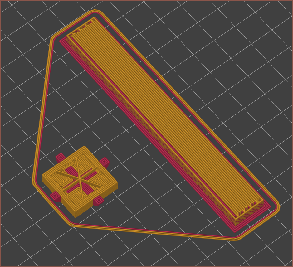
    Setting up in PrusaSlicer

    So I was doing things like setting up a decent purge volume and looking at the (failing) prints to see that I really needed to work on retraction settings. What I found that it seems best to
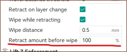
    • retract ASAP - prevents a blob forming at the end of the track
    • deretract slowly - allows a small blob to anchor at the new location before the toolhead zooms off

    At this moment, my purge volume was 300mm3 and it seemed like it needed to be more. For context, 100mm of filament = 240mm3, so it's somewhat expected. I designed the Coaxial8or more for having a digital library of filaments than a multicolour modification (e.g. like the diamond nozzle).

    Setting up OrcaSlicer

    In search for "coasting" for PrusaSlicer, I found out that OrcaSlicer has a "wipe distance" option, which doesn't exist in PrusaSlicer.

    Earlier in the year, I didn't use this slicer because it only supported single-extruder-multimaterial options. I can now report that it now supports multiple extruders! The only caveat is that, to duplicate settings across all extruders, I have to temporarily set Extruders = 1 and then back to = 16. This also resets the filaments loaded to whatever was in the first extruder.
    The main, exciting thing I was able to (convolutedly) set up was a "master" material, which actually updates other materials inherited by it. This makes things SOOO much more manageable.
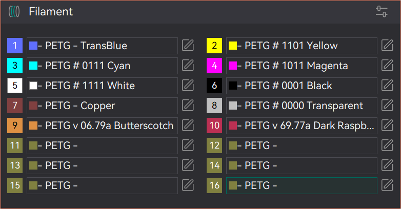
    I also think it's easier to see what is loaded in OrcaSlicer:

    It's possible to do by creating a new material by clicking "Add/remove filament" and then "Add new":

    It insists that some "@MyMarlin" thing is added to the end. I went to the presets path, removed "@MyMarlin 0.4 nozzle" from the filenames and then search and replaced (with nothing) the string in other files:
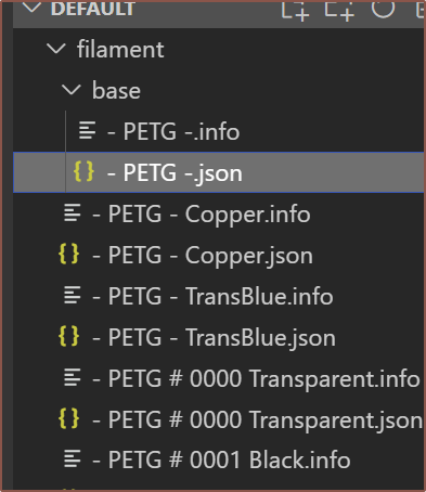
    As you can see, I decided to name the block colours with a 4-bit number. So instead of hex of RGBA being FFFF for opaque white, it's 1111, since the block colours are either entirely on or off anyway.
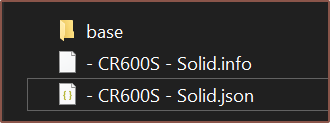
    It was a bit tough (because I kept opening the same .3mf instead of importing it into a new project, causing settings to linger around) but I was able to do the same thing with the printer preset! All I needed to do is put my master in a "base" folder and set 

    "inherits" : ""

    Then I could make another profile and tell it to inherit the master. 

    Finally, I can have an easily editable master profile! I've been wanting this feature ever since I got into 3D printing. What makes it special is that, if I changed a value in the child preset and I want it to follow the master again, I just need to change the value to whatever it was in master. It's not like Cura where I'd have to open the config file in VSCode and delete the entry.
    It's a bit hard to see, but settings that are different from the master preset use white font and unchanged ones are a light grey.

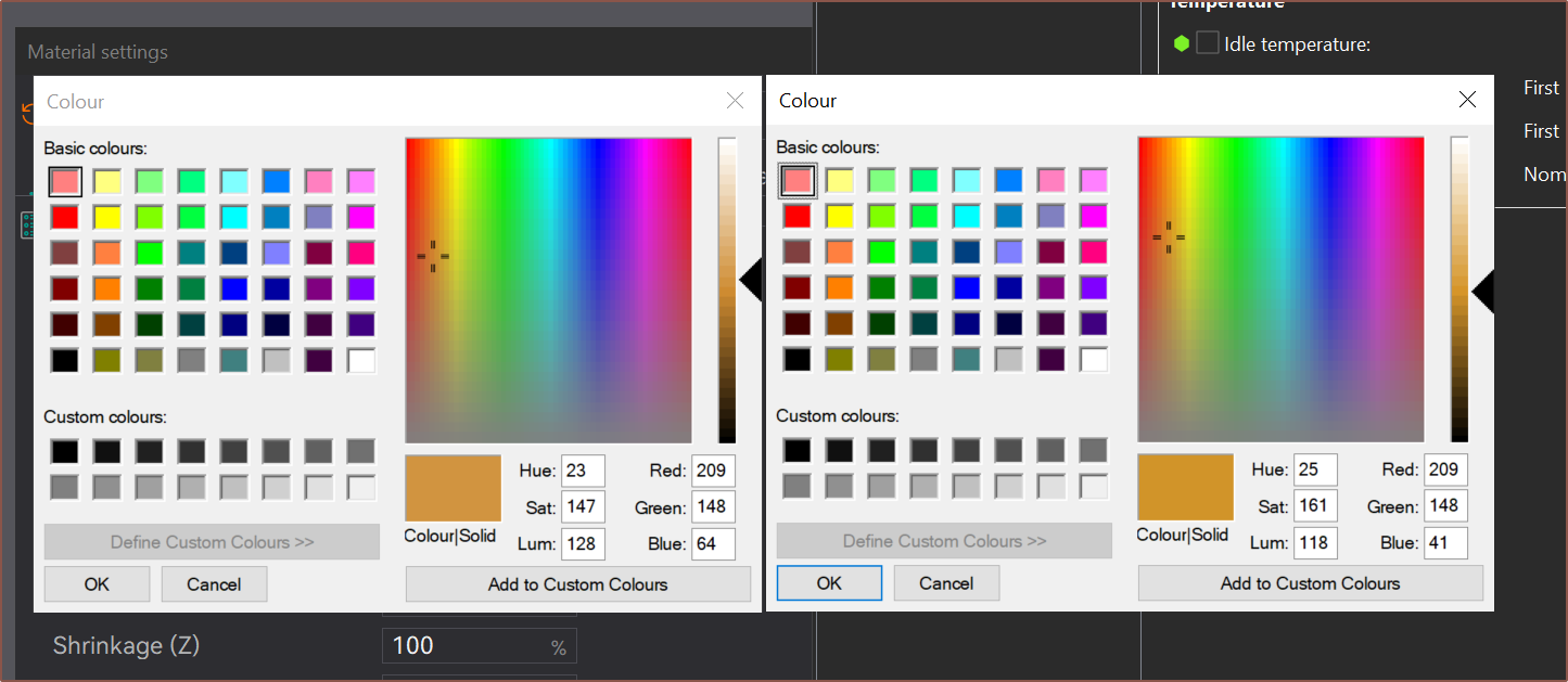
    Redefining colour

    Do you see much of a difference in these colours? I don't, but the blue value is quite a bit different. I then remembered that all these virtual materials are going to be sorted in alphabetical order. If I continued to use RGBA, it'll be all over...
    Read more »

  • [M] Leak shield and channels

    kelvinA12/23/2024 at 10:32 0 comments

    I've added a leak shielding to the thermistor grub screw. I've also removed some leak channels and made the remaining ones deeper in depth so that leaks:
    • can be detected faster
    • have less "crosstalk", potentially making it harder to determine leak origin if 2 filaments are of similar colour
    • don't pose a threat to the thermistor
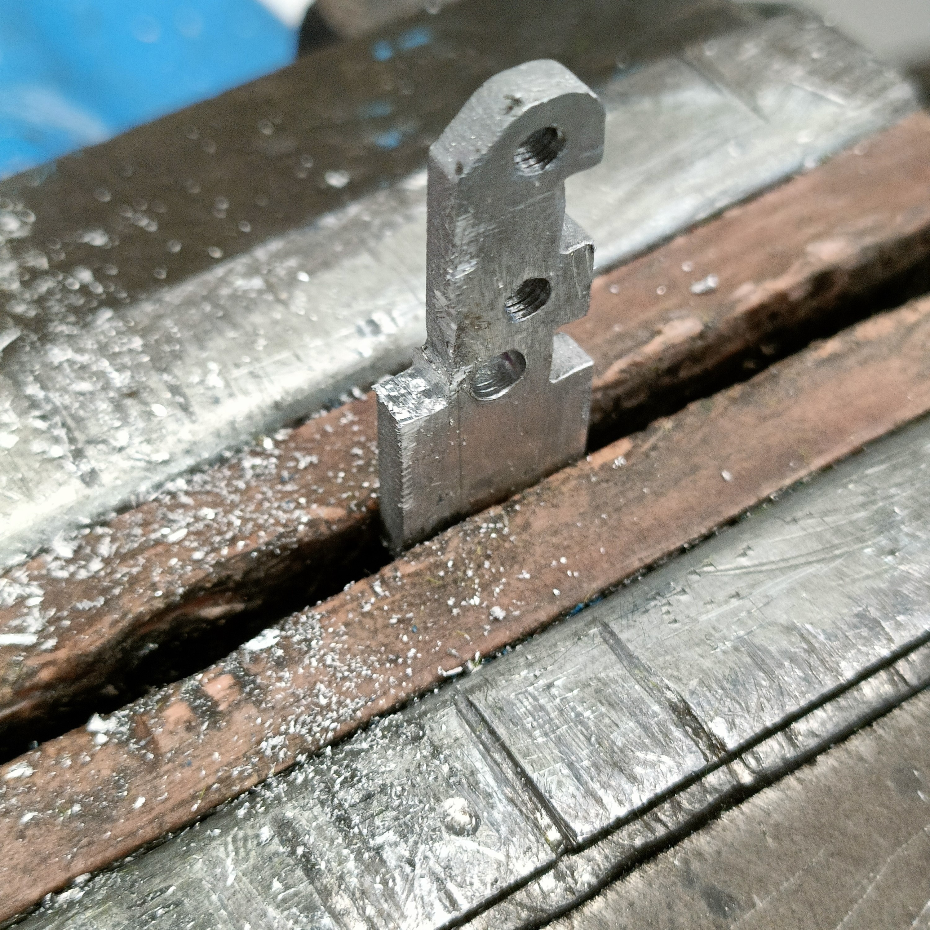
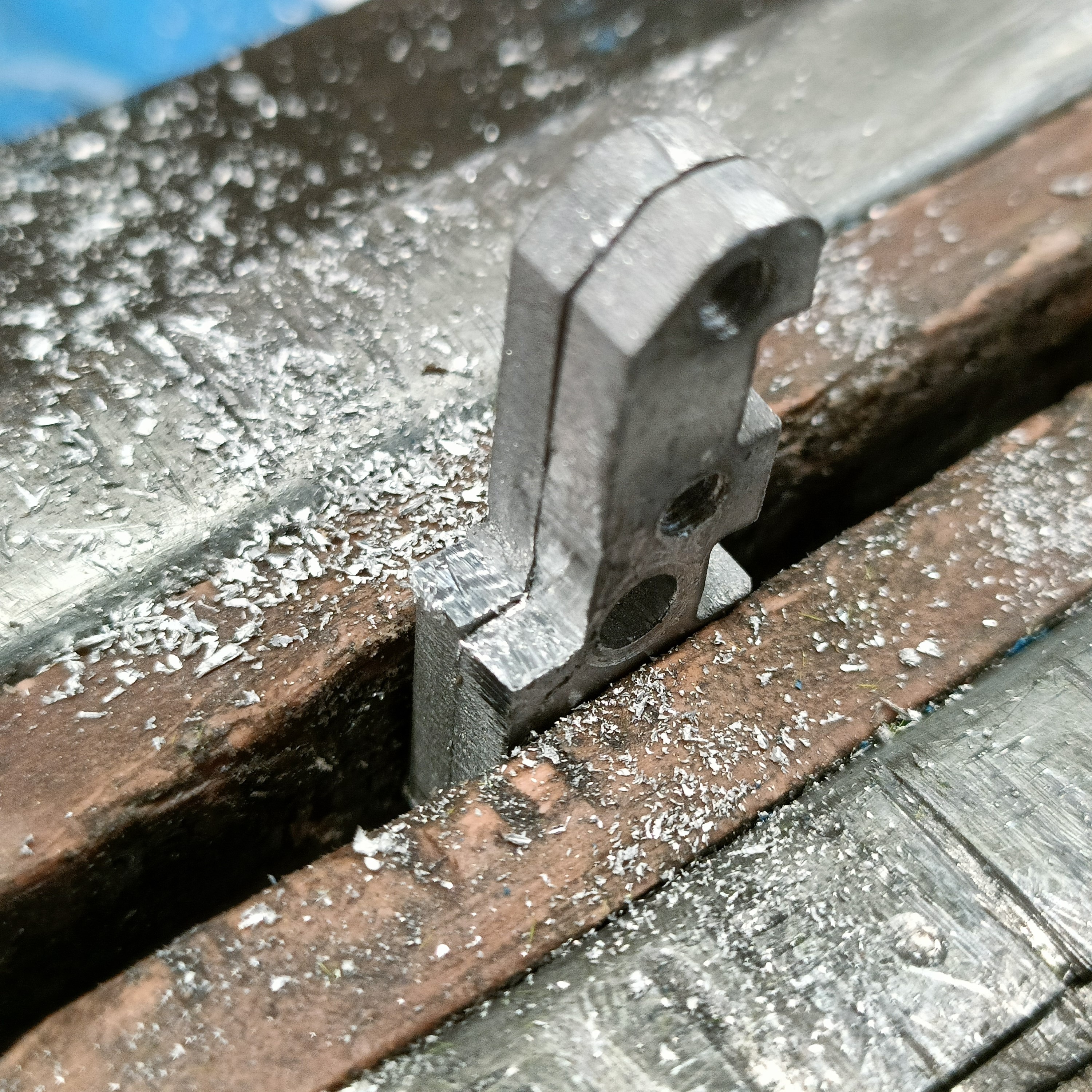
    • can more easily flow out the sides instead of squeezing through the small gap between the coaxial8or and clamp plates

  • [E1][X] Overtightening and undercooling

    kelvinA12/22/2024 at 17:16 0 comments

    I now know that aluminium is unquestionably not suitable for the clamp plate. Why? Well, I tightened Ch6, the black channel, and 3 metres worth of test prints later, I had this superblob from Ch7, the copper channel:

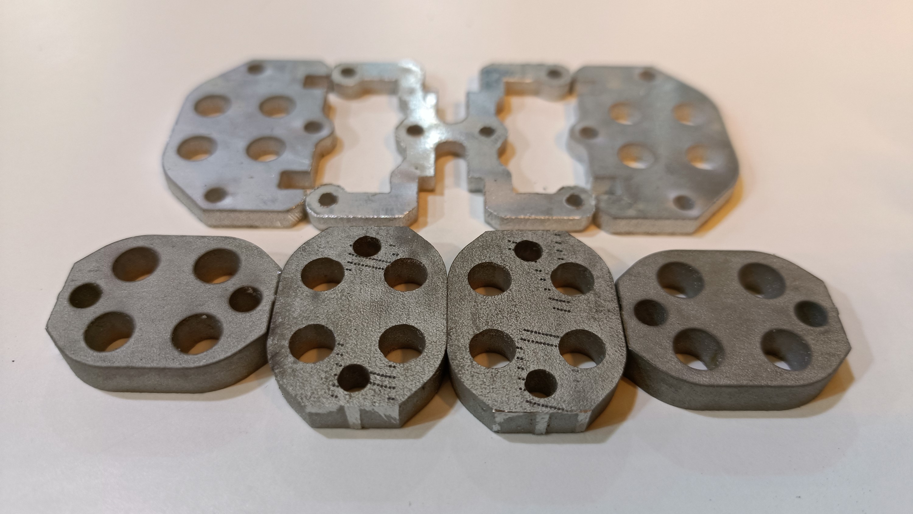
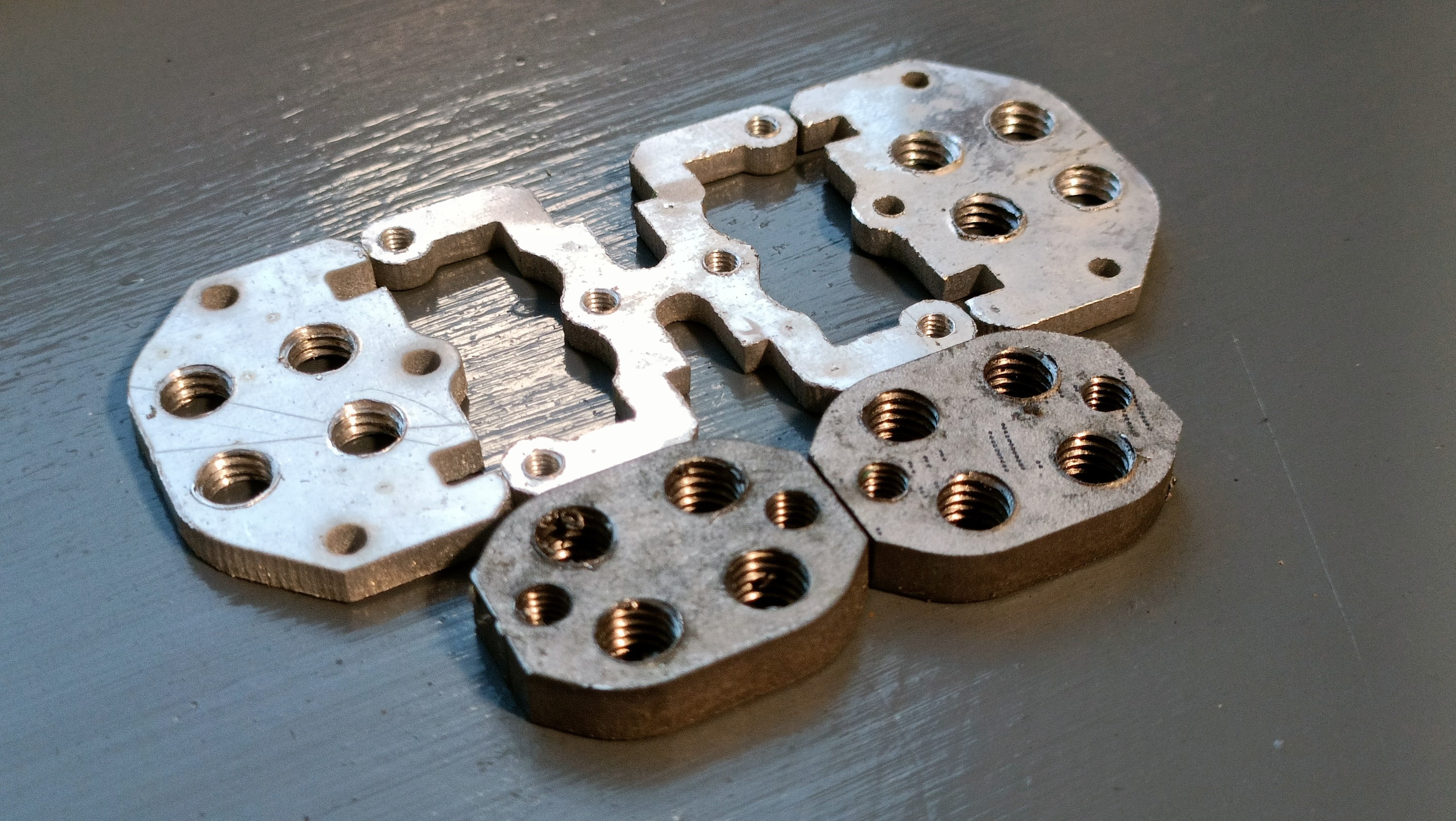
    Next month, I'll try and get them cut and tapped out of stainless steel. I can't find sheets, but I can find 5mm bar that should work for these 20mm wide mini-plates:
    In the meantime, I've tightened the leaking channels just enough to feel resistance, trying not to tighten them such that the plate bends up. I then proceeded to print a combination of Ch1-4 for 1 metre to try and see what channels are leaking, and it doesn't seem like the max flow rate increases. This isn't much of an issue for the CR600S as 17mm3/s limited speeds paired with recently-calibrated 3600mm/s2 acceleration prints nice and snappy. 
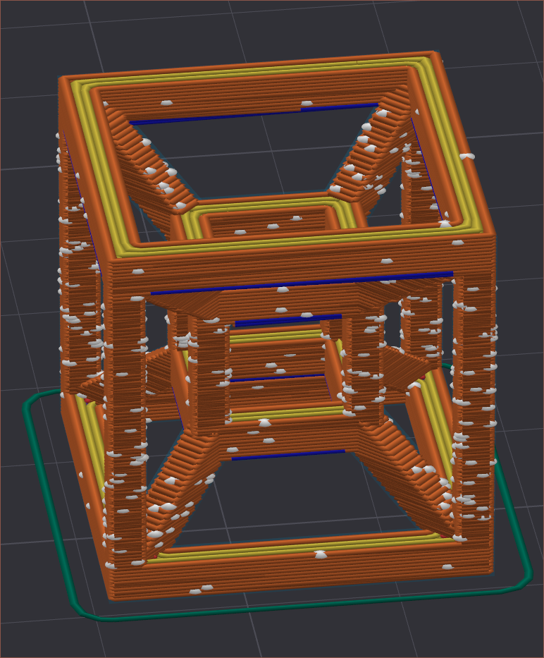
    Hilbert-curve infill test. Left is the first one and the right is when visible improvements started to show. 

    I still need to calibrate M592, since my walls at this speed are 0.48 when they should be 0.68mm. Part of the 30% loss of filament could be attributed to leaks but it's unlikely.

    I'd also like to mention that Ch3 clogged when I tried 36mm3/s feedrate, but unblocking was as simple as removing the part cooling fan, allowing 20 seconds for the heatbreak to heat up in the time it took me to send the command to extrude through the channel at 1mm/s. This provides additional evidence that a heater-controlled "valve" will prevent accidental backflow of unloaded channels. It should also mitigate clogs caused by heat creep in unused channels. For consumer-level reliability, it should be paired with a filament sensor so that the valve can only be turned on if the channel is both used and loaded.

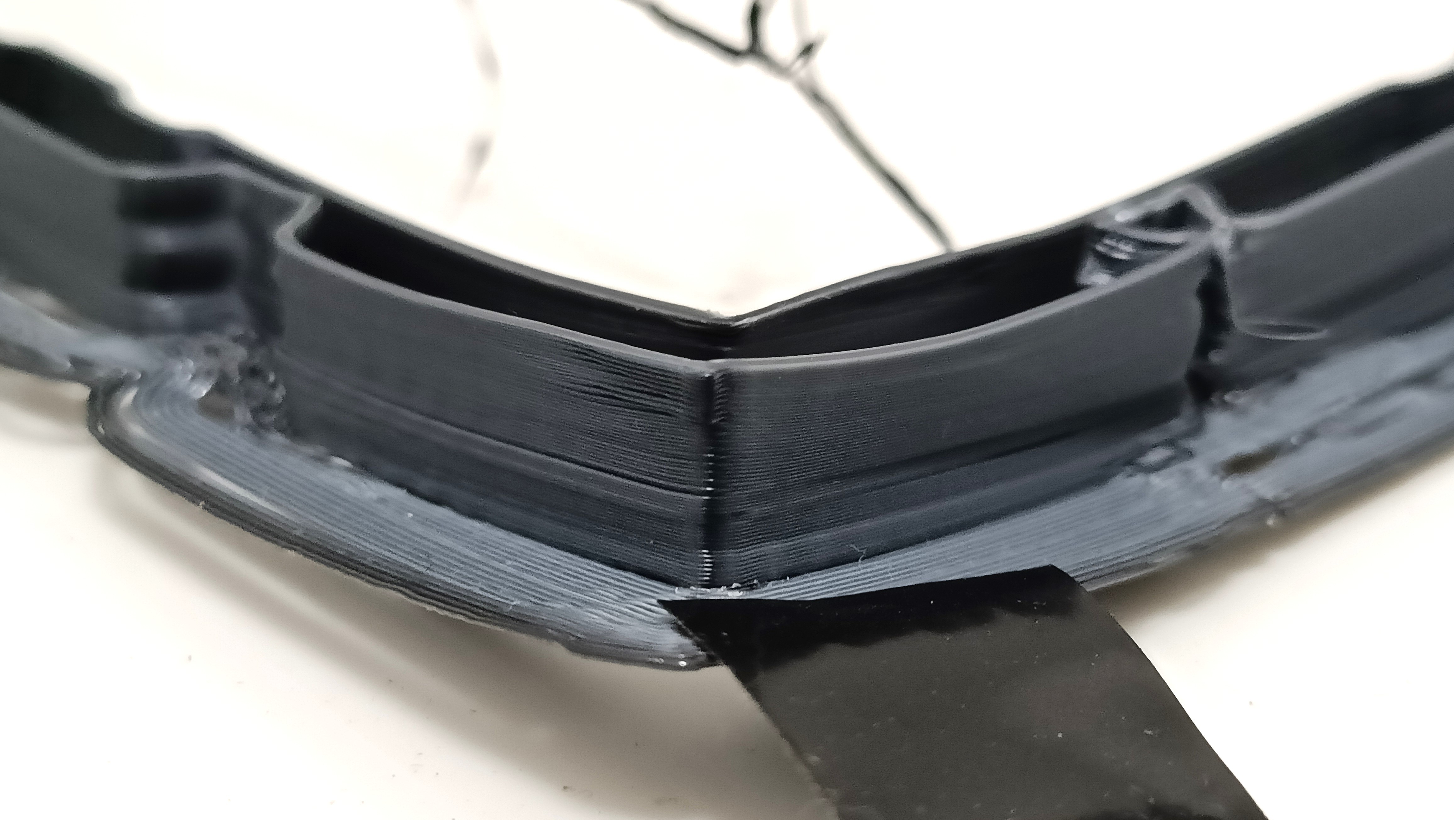
    Moving on, I wanted to see what my cooling performance was before I tried to redesign the front cover of the coaxial hotend. I set a print for a 1 : 1 mix of White : Black, but accidentally did Black : Copper. In any case, I stopped the print when it was obvious that cooling was inadequate. The only 45-degree overhang that came out good was the one directly in line with the cooling duct:

    The southeast one is the one facing the front of the printer. The northwest one is the one closest to the cooling duct.
    The copper printed here indeed looks darker than the raw filament.

    [Dec 30] I just remembered that I printed a temperature tower months ago, and considering the bridging difference between 236C and 218/224C, it's probably not helping that I was running this overhang test at 242C throughout. I'll just use 242C for bed adhesion and 224C for subsequent layers.

  • [M] Split-half hotend holder

    kelvinA12/19/2024 at 17:26 0 comments

    I've -- once again -- redesigned the hotend holder.

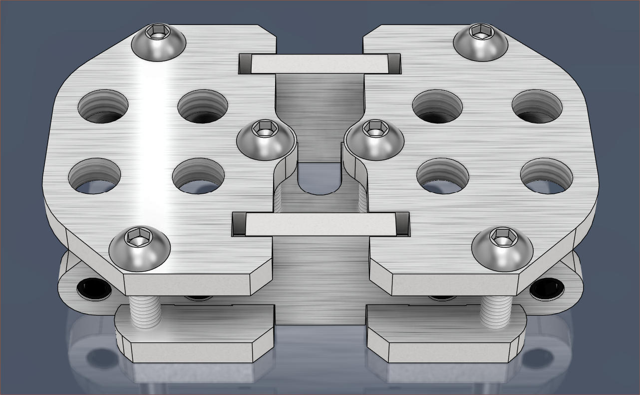
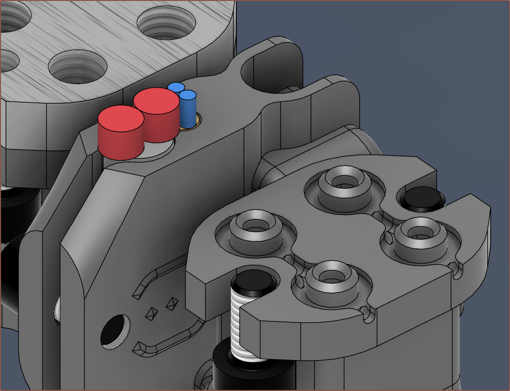
    As you can see, the HolderTop plate has been split in two and the HolderBottom plate now allows the wires to go straight up. Unlike the first hotend holder design for Coaxial8or R0, the wires can easily exit the holder by removing the HolderFrontBack plate.
    This design is closer to my vague, initial idea of what the holder would be like when I had the decision to change the Coaxial8or input arrangement, just that I thought that the two plates that hold the couplers would be directly connected to a "HolderTopConnector" plate instead of this arrangement. 

    You may also notice the chamfers, and that's because I found a squashed thermistor wire when I went in to inspect for damage before embarking on more acceleration / linear advance / junction deviation tests.

    I also encountered more leaks:
    Presumably Ch1 that is pushing out yellow that was still inbetween the hotend and plates.
    Ch 6

  • [E1][X] Test circles, leak cleanup and flow tests

    kelvinA12/17/2024 at 23:16 0 comments

    I reverted the directions of the extruders, now a lot easier without the washers, and printed a pancake with all channels and the print completed!

    I finally figured out that 224C is too cold for the PETG to stick on the bed and had more success with 239C. During the print, I did hear filament slipping. I could then feel each of the filaments to find out which channel had the issue.

    I wanted to see if the flow issues have been solved so I did another print in white. This had a few problems. 

    The Z axis sounded like it might have skipped a step, and it showed in the print and had to babystep. I've now increased current from 0.6 -> 0.9A. Now that I'm typing this, I'm also considering increasing the Z_HOLD_MULTIPLIER (the current when the motor is not moving) from 0.5.

    Additionally, I had set PrusaSlicer to move at a speed limited by 30mm3/s, but the channel choked and was only stable at around 40%, hence the expectation is 12mm3/s of flow per channel. 

    I was also doing some in-situ linear advance testing to see if it was working.

    During this print, I could see in the leak detection window some yellow that was coming out, which means that it's channel 2:

    I could also see some transparent blue (and a little bit of white) eeking out of the output channel, so I cleaned this off and tightened at 220C:
    After tightening the nozzle, I unscrewed the hotend and started to clean off the yellow before tightening its channel. It's nice to see that the leak channels work as intended.
    As you can see, it looks like some transparent blue is also in there so I used needlenose pliers to try and tighten its channel. Unfortunately, the cartridge wire takes up more space than I expected, meaning that 2 of the 8 heatbreaks are unturnable by the wrench, and I'm thinking that a revision to the hotend holder could help fix this issue. It could also be cyan so I've gone around and tighened that too.

    Now, since the Coaxial8or is out and in the open, I thought it was a good a time as any to heat to 240C and find the flow limit using this guide with the following changes:

    • I used a crocodile clip from my hydra "helping hands" thing (seen in a previous log when it was holding the extruded filament)
    • I used 112mm because that's the length of my screwdriver

    The feedrate values I tried, in order were:

    • 300 (worked, but probably doesn't count since the hotend wasn't fully pressurised)
    • 600
    • 450
    • 360
    • 330
    • 300 (didn't work this time)
    • 240 (worked)
    • 270 (didn't work)

    I then extruded 200mm through channels 2 - 8 with F240 as seen below. This corresponds to 240 / 60 * 2.4 = 9.6 cubic millimetres/second/channel.

    There were no leaks to be seen. 

    What's that? Big Leaka's stocks are tanking?
    "Don't like it? 1 v 1 me" meme

    The flow rate is still disappointing though. I don't think there's even been a change over the previous designs.

    [Next Day - 14:00]

    I decided to set all motors to 900mA current, which should be in acceptable limits since the extruder motors are rated for 1000mA. Since non-moving extruders were perfectly fine, even way back at the start of the year when I set the run current to 450mA, I have also halved the default hold multiplier to 0.25:

    Redoing the test at 240C, I was able to consistently extrude 300mm at F450 (7.5mm/s) through a 0.6mm nozzle, meaning that the volumetric flow has now increased to a respectable 18mm3/s per channel. The extruder motors are lukewarm.

    [16:30

    Decided to move past arbitrary limits and set 1A current for all motors. The steppers and the driver heatsinks are still barely warm, but the feedrate has increased to 510mm/min (8.5mm/s) for a volumetric flow rate of 20.4mm3/s. Since filament in some channels started to slip over the gears, I believe it's right on the edge and a flow limit of 19.2mm3/s should be used for printing. 

    In other words, the Coaxial8or speed limit is 8mm/s with my present setup.

    Volumetric rate of 19.25mm3/s calculated to be a filament speed of 8mm/sSome yellow is starting to creep out again so I need...
    Read more »

  • [X] SANPrinter Dual Drive Extruder can't be used in reverse

    kelvinA12/15/2024 at 15:49 0 comments

    This is Channel 7 (E0-7 translates to Ch1-8 respectively)

    So today I did the following: 

    • installed the fans
    • installed the bowdens
      • trimmed the bowden of Ch 4 from 48 to 43cm
    • heated the hotend and manually extruded the channels.

    Ch 7 was the last one that I needed to do and it turned out to be the one to pop out, revealing that the input bowden coupling is merely just a friction fit. It seems like this coupling form over function; it looks nice but, as you can see, won't stick around for the long term. I never knew such a collet existed, but it could be useful if paired with a grub screw.

    (Note: SANPrinter also goes by the name SANBrother)

  • [M] 5mm motor holders and reversed extruders

    kelvinA12/06/2024 at 14:11 0 comments

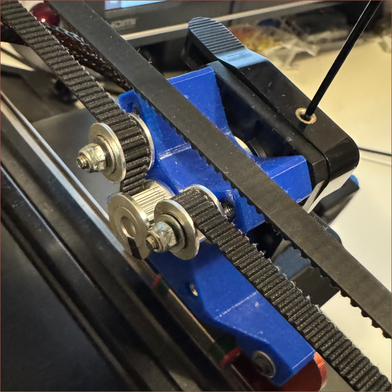
    These substantial looking plates are 5mm because it's the same thickness as the clamp plate and it's thicker than 3mm. If you remember all the way back to the start of the year, I had to use washers because of the DDEs (aka BMGs). Since I was planning on inverting the DDE's closest to the hotend, I thought I might as well correct my earlier error. 

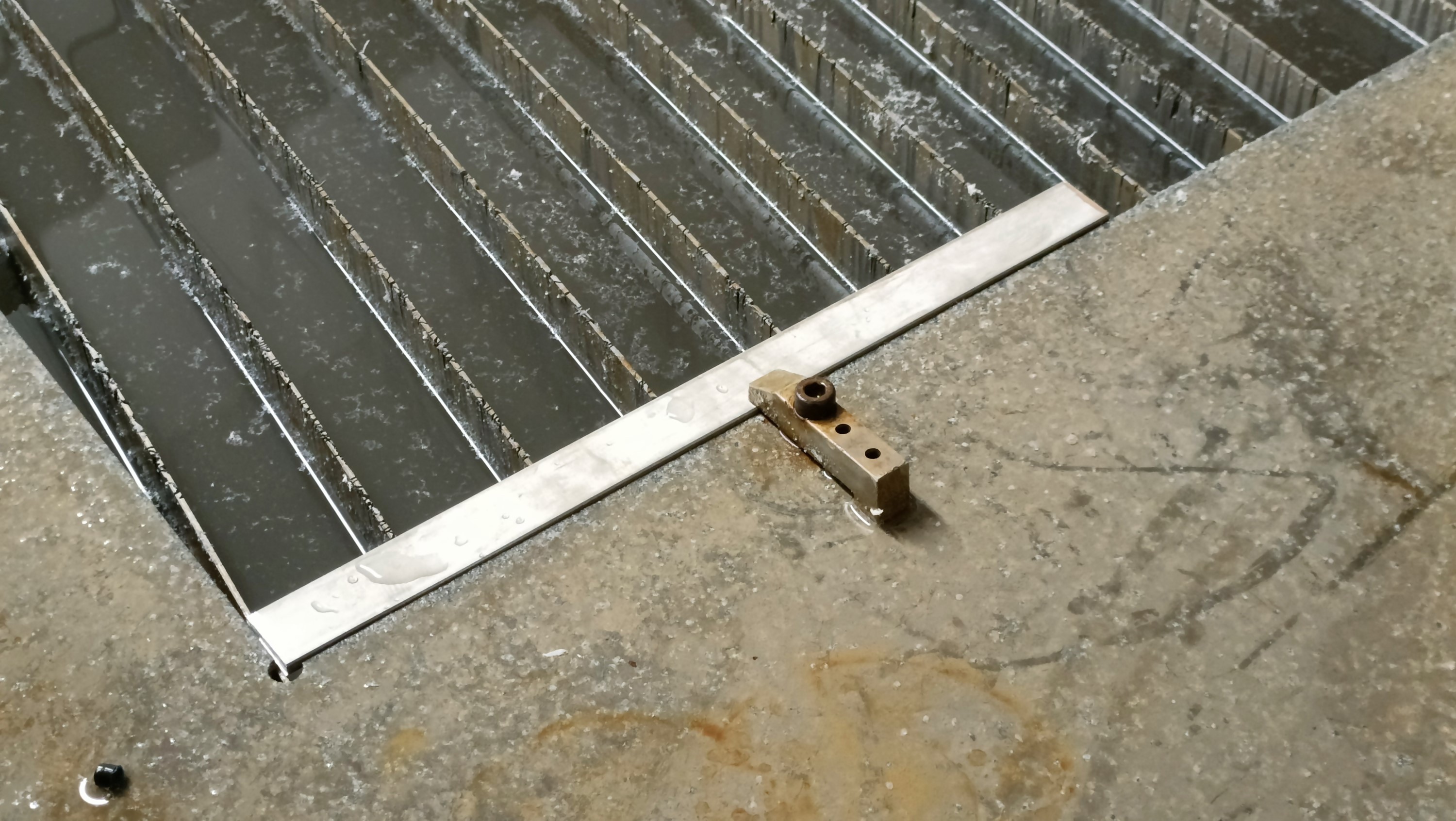
    This is what it looked like when they were being cut out on the waterjet:
    The uni only happened to have M5 x 20mm bolts, so I used the M5x5mm brass insert strategy to "shorten" the threads to M5x15mm whilst undergoing the installation:

    It was much easier to install the DDEs and they feel more solid/secure. I've been able to shorten the bowdens E0, E1, E6, E7 by 5cm, down to 30, 30, 30, 35cm respectively (about 14%). Additionally, it's much more ergonomic to reach the large gears on those extruders now.

    In other news, I've found a good Autodesk Fusion texture that seems to look similar to the waterjet cut edges:

View all 123 project logs

Enjoy this project?

Share

Discussions

Trovoski wrote 09/18/2024 at 13:20 point

I have been following this project for months, and it's my go to morning reading when I clock into work, haha

  Are you sure? yes | no

kelvinA wrote 09/18/2024 at 13:53 point

Waw, that's great to hear! I do occasionally wonder if these logs are being sent out to a void as dark as this site's colour scheme, so it's reassuring to see this.

  Are you sure? yes | no

MasterOfNull wrote 08/11/2024 at 22:48 point

If you route a path in your AL and add a cover, water cooling.  Probably lighter.

  Are you sure? yes | no

kelvinA wrote 08/12/2024 at 08:47 point

What do you mean by "add a cover"? 

As for water cooling, I decided that I didn't want to include its complexity nor potential for leaks.

  Are you sure? yes | no

MasterOfNull wrote 08/12/2024 at 15:18 point

Oh.. I was just saying with your existing design you already have a nice block of AL right where you need cooling.  Route a channel in the top for water to flow around and cover with a plate to contain it. Air cooling works too and is simpler, yes.

  Are you sure? yes | no

Joshua R. Taylor wrote 10/05/2023 at 13:22 point

OMG!!!! we need to talk! josh@jrt3d.com

  Are you sure? yes | no

Similar Projects

Does this project spark your interest?

Become a member to follow this project and never miss any updates