 kelvinA
-
[M][T] Internally groove the heatblock-heatbreak mating surface?
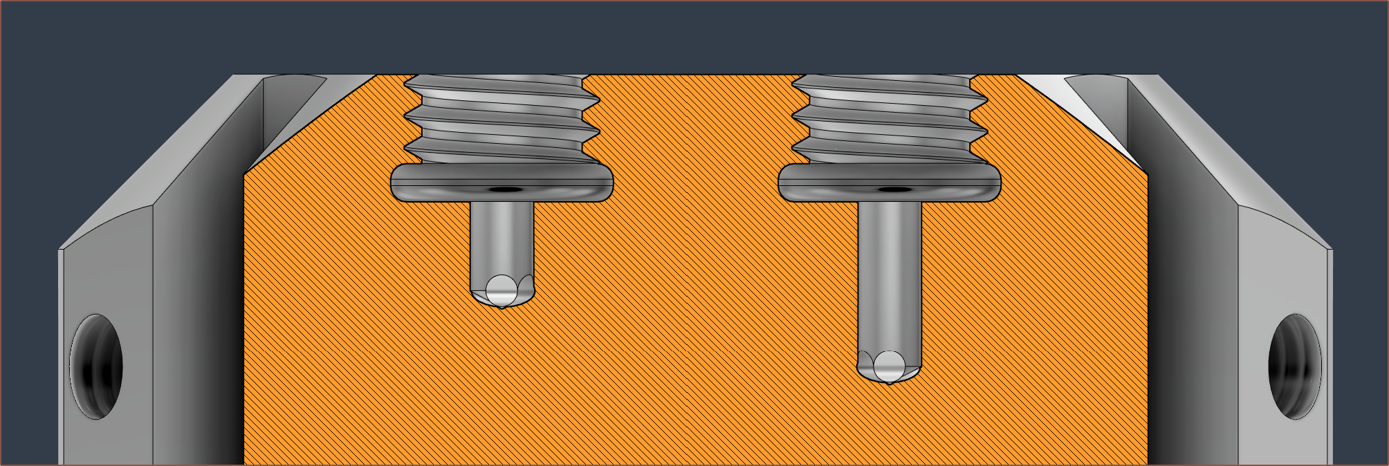
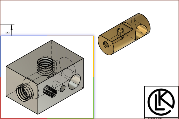
09/25/2023 at 21:09 • 0 commentsI have a diamond hotend I never got around to using and I looked at the M6 thread inserts to see what was done for that heatblock, and it looks like the bottom-most threads a missing. It actually looks like there's a very slight undercut. This is likely due to the inability to perfectly tap all the way to the bottom of the blind hole. I'm hypothesising that this is the reason why I got leaks.
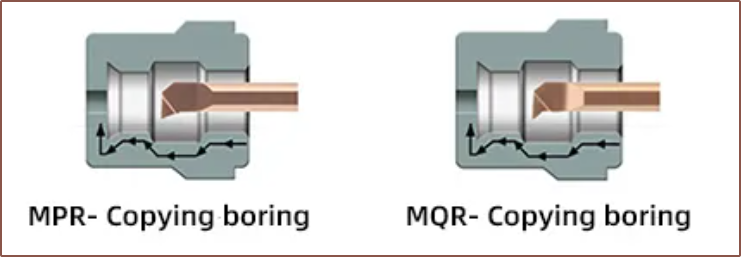
To counteract this, I've added more internal groove cuts to the bottom of the threads. It's rounded because it uses the same tool as the coating grooves, though something like an MPR or MQR looks to be more of a match for this.
-
[M] Visible indication of full grub tightness
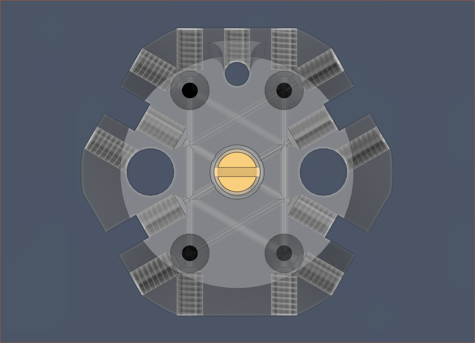
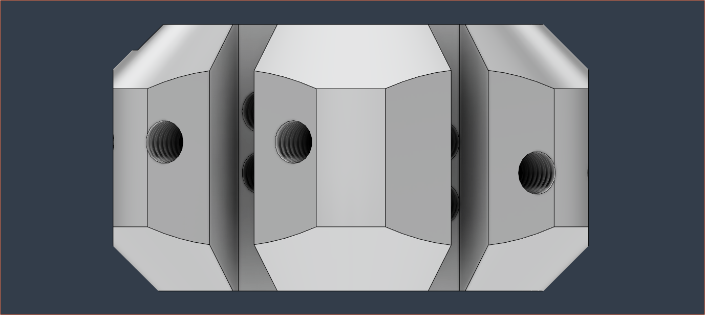
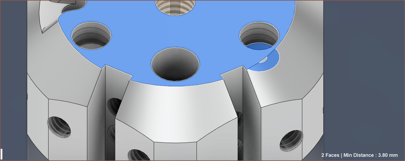
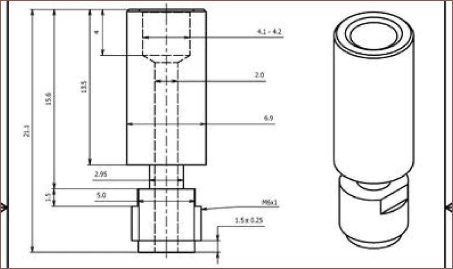
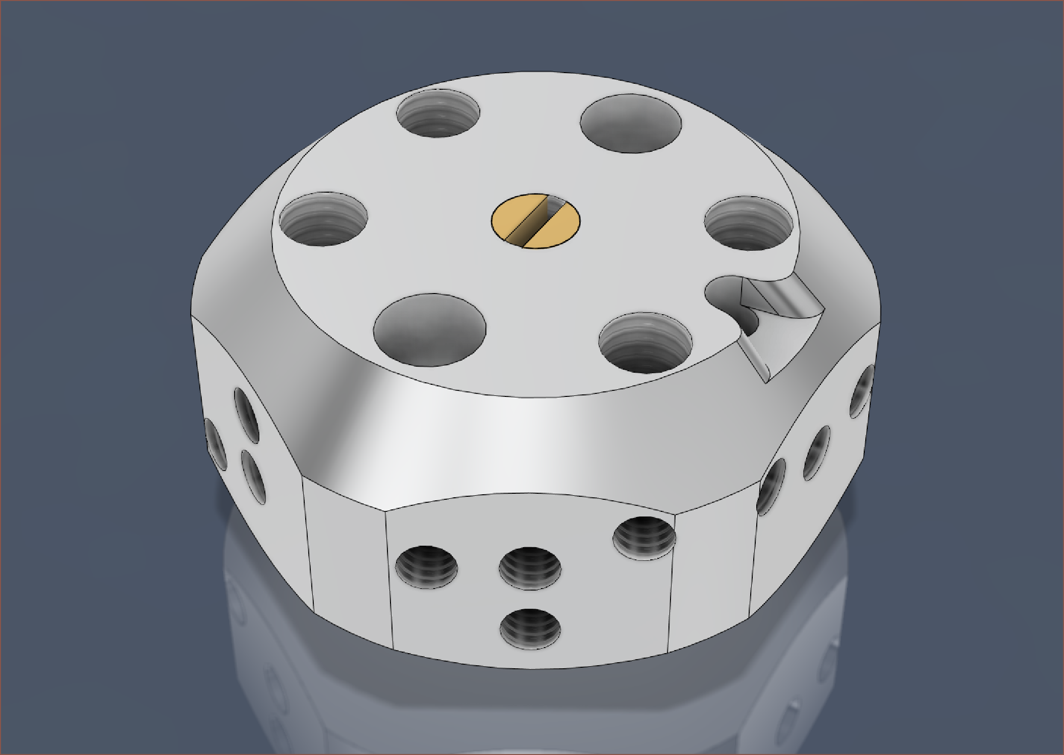
09/24/2023 at 22:21 • 0 commentsBack in May, the technician that fabricated the first prototype suggested that the grub screw length should be flush with the face so that it's more visibly obvious when the grub is fully tightened or not. Thus, I've added some 4mm trenches so that the actual length of the screw+ball bearing stoppers are the same everywhere.
I've also had to reduce the depth of the heatbreak threads to prevent the topmost grub void from creating holes in the mating face. I've ensured there's at least 1mm of wall thickness.
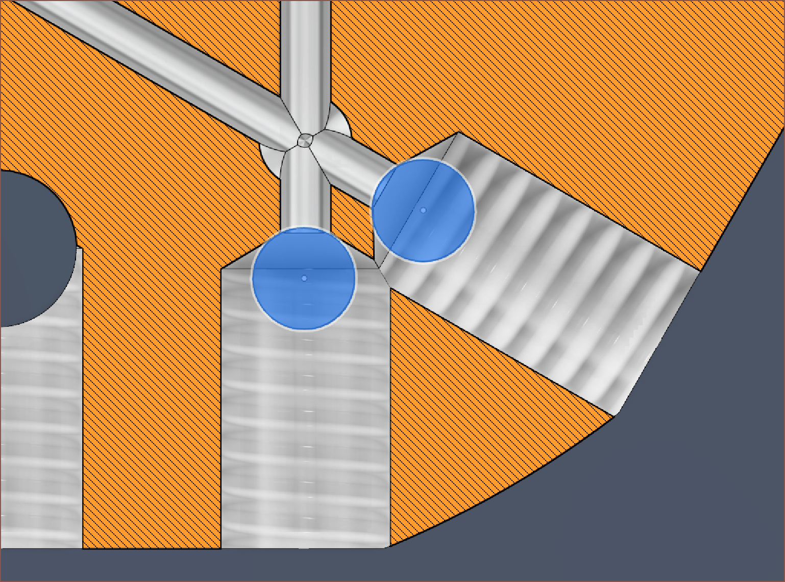
Using a 2mm ball, and a 4mm grub screw, the top of the screw should be just-about below the surface. It might be better to use a 2.5mm bearing to be even closer to the exact length.
-
[P] Outer Cover and leak detected
09/20/2023 at 18:02 • 0 commentsI've finally printed out the outer cover to see if there's any obvious issues, but more to make sure it's printable in the first place.
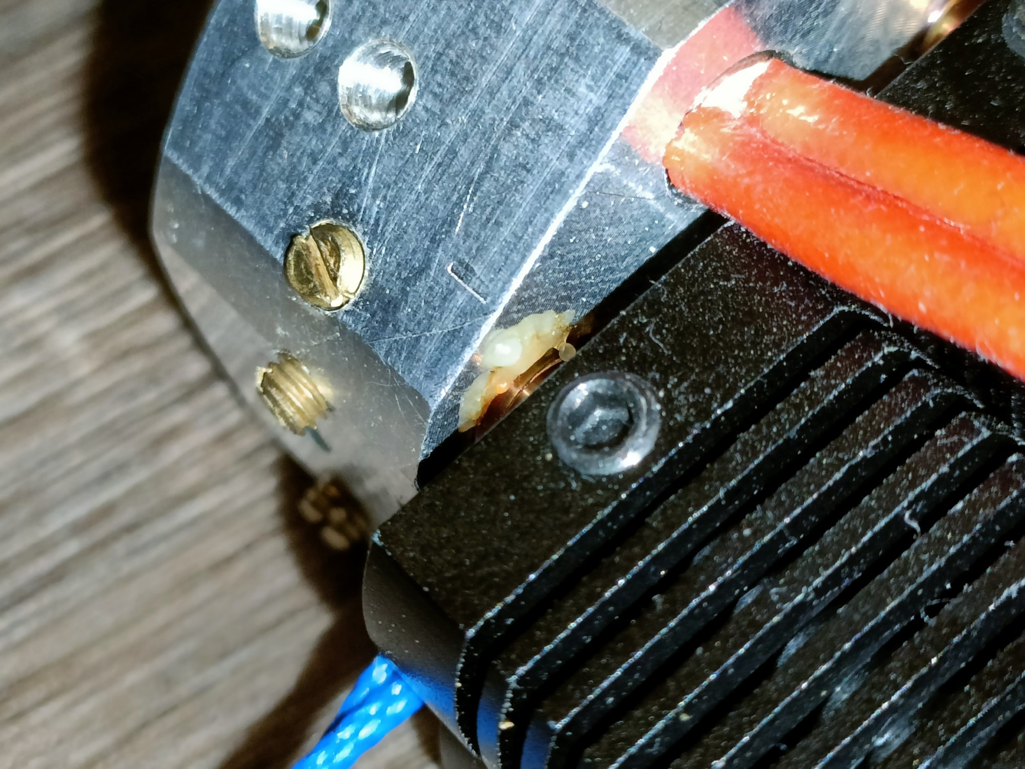
I've also looked a bit closer at the hotend and noticed that 2 of the 4 heatbreaks actually leaked a small amount of material. Considering I've only put in a small amount of material, I'm going to have to some cleaning and tightening. At the same time, I'm actually not sure on a suitable strategy for actually going about sealing that still allows the hotend to print at 250C without offgassing concerns.
I think a good place to start is getting heatbreaks that can be tightened using a wrench. Unlike traditional hotends where the nozzle is tightened to provide the seal, the tightening has to come from the heatbrake with this kind of design. The E3D Cyclops seems to adopt 2 flattened parts of the thread to allow for this:
It's likely so that the torque of tightening the heatbreak doesn't risk shearing the thin heatbreak section. One of the issues I'm encountering in my mental simulations is that there's a lot of stuff around the heatbreaks (such as other heatbrakes or thermistor wires) that would seem to make a wrench-tightened solution difficult.
-
[T] Hotend hypotheticals: Off-centered inlet approach?
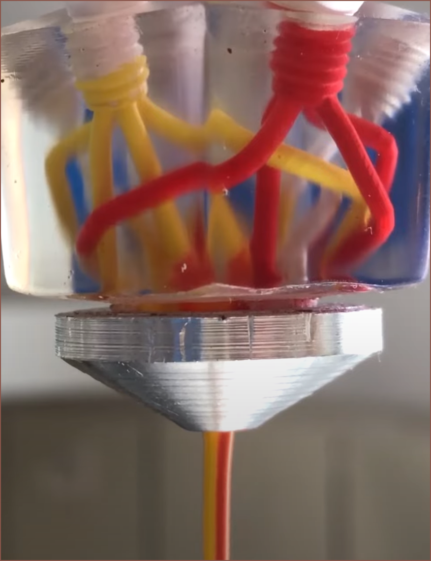
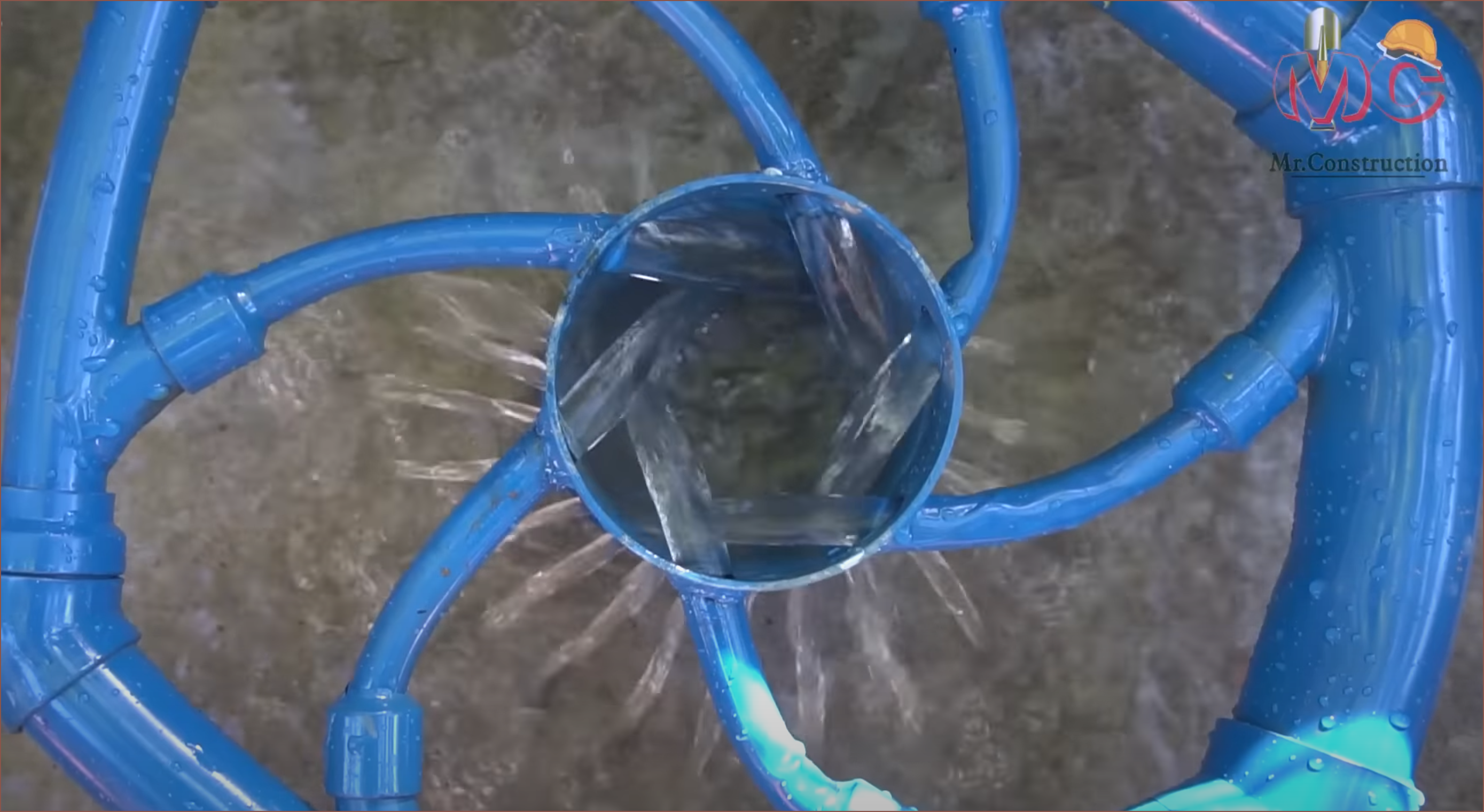
08/29/2023 at 14:09 • 0 commentsHeinz has recently uploaded a video showcasing version 3 of his design, which looks like this:
The main improvements is that it now has a third coating colour and that the material now comes around in 4 positions instead of 2 in an effort for even better coating. However, a notable snippet is this:
In the months I've been staring at my CR600S instead of fixing it and testing the coaxial hotend, I've been trying to hypothesise as to why this general hotend design could be a promising solution to colour mixing.
1] Mixing across a curved line instead of an infinitessimally small point
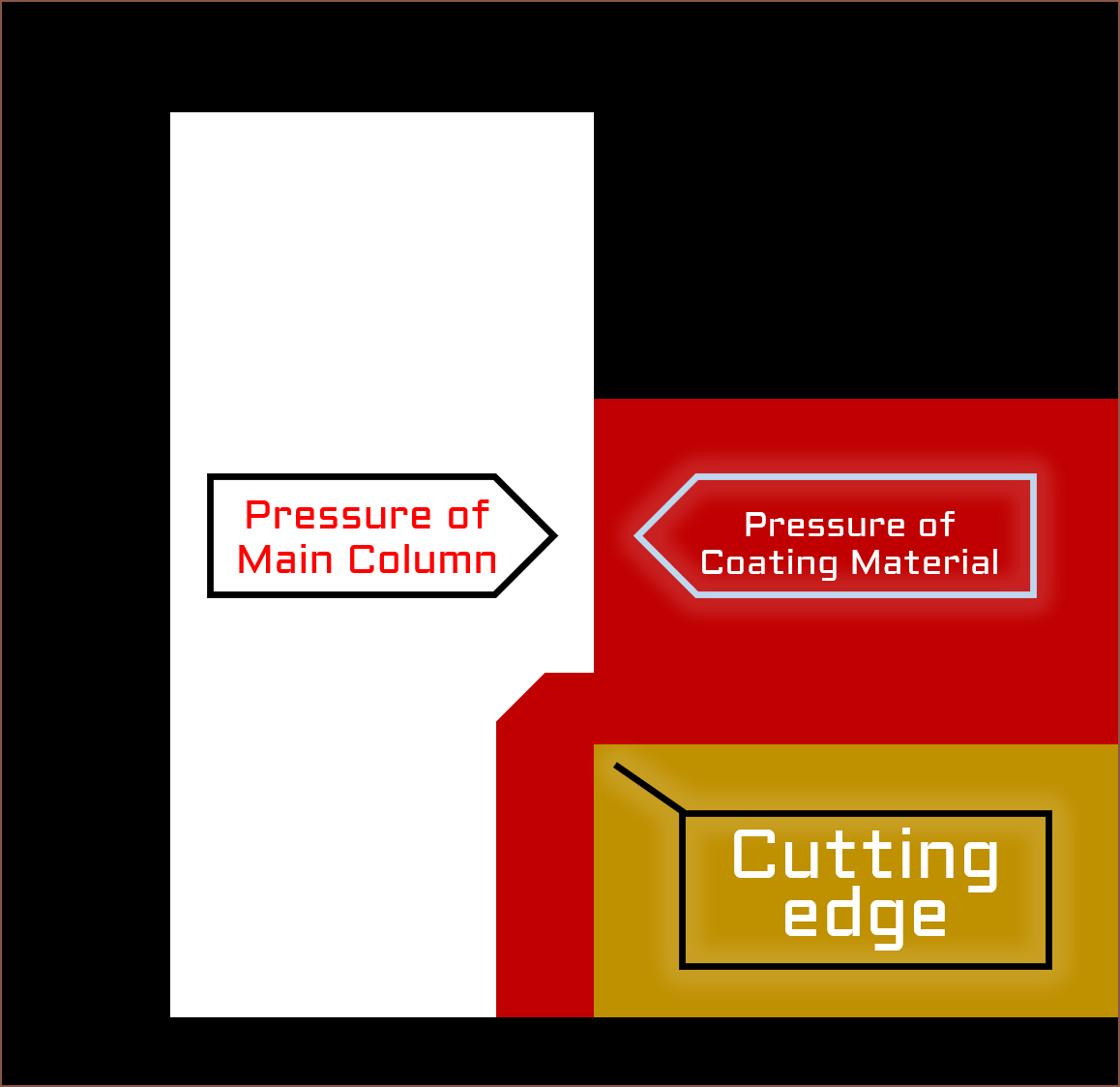
Part of the reason why I wanted to look into a machined hotend was to ensure the geometry of what I'll call the "cutting edge".
This image shows what I predict is happening at the point of this cutting edge. Similar to how a pencil sharpener cuts off a thin strip of wood, this edge would cut off any coating material where the pressure exceeds that of the main colum, slightly pushing it past the edge.
To coat a cylinder, the above diagram would be revolved by 360 degrees around the leftmost edge of the Main Column. Thus, the goal is to obtain a uniform pressure of the coating material around this 360 degrees.
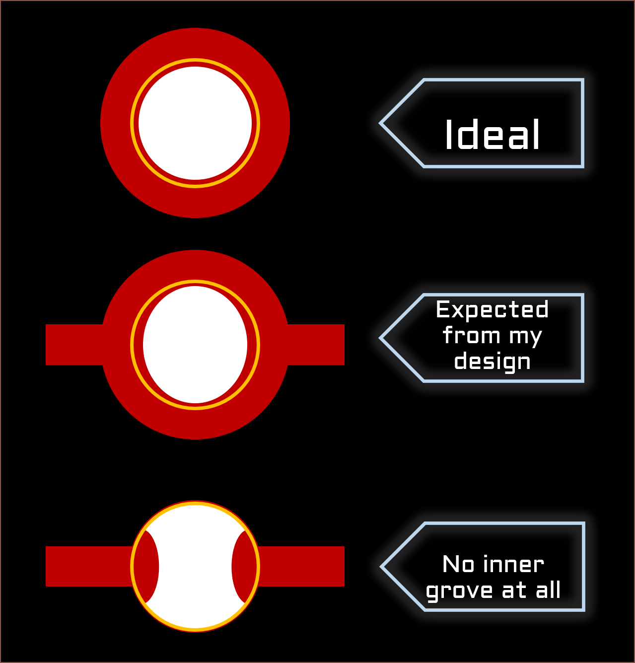
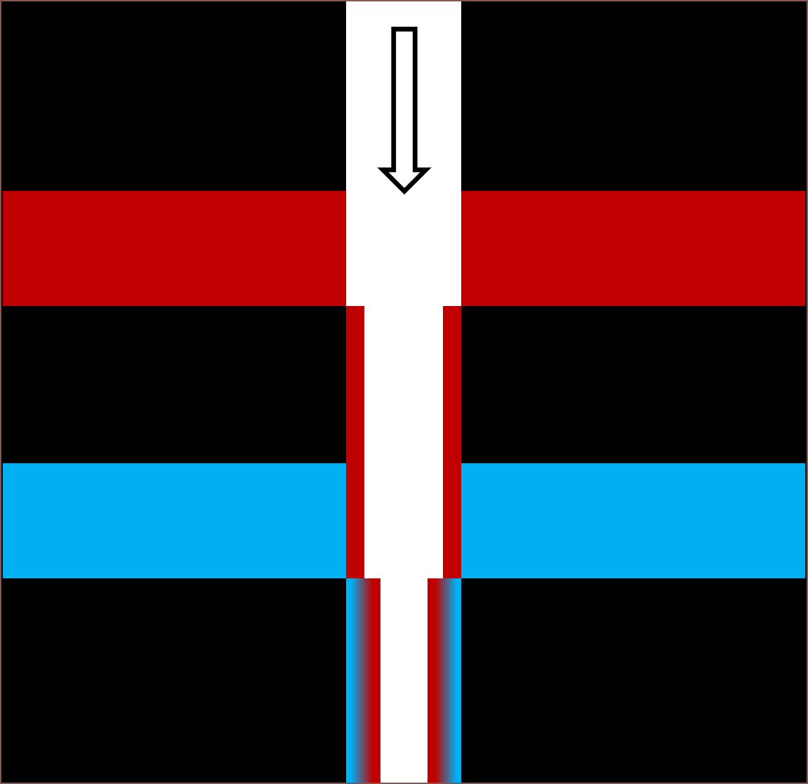
2] The internal groove reduces the pressure difference
Here is another diagram to illustrate what I mean, whereby the cutting edge is shown by a gold ring:
I haven't done any fluid simulations on the bottom two, so it was just a guess as to what the cross sections would look like.
Back to the image I highlighted, it seems that, as the acrylic paint is less viscous than the thermoplastic that Heinz used in his first version, the pressure differences are more apparent, looking like this:
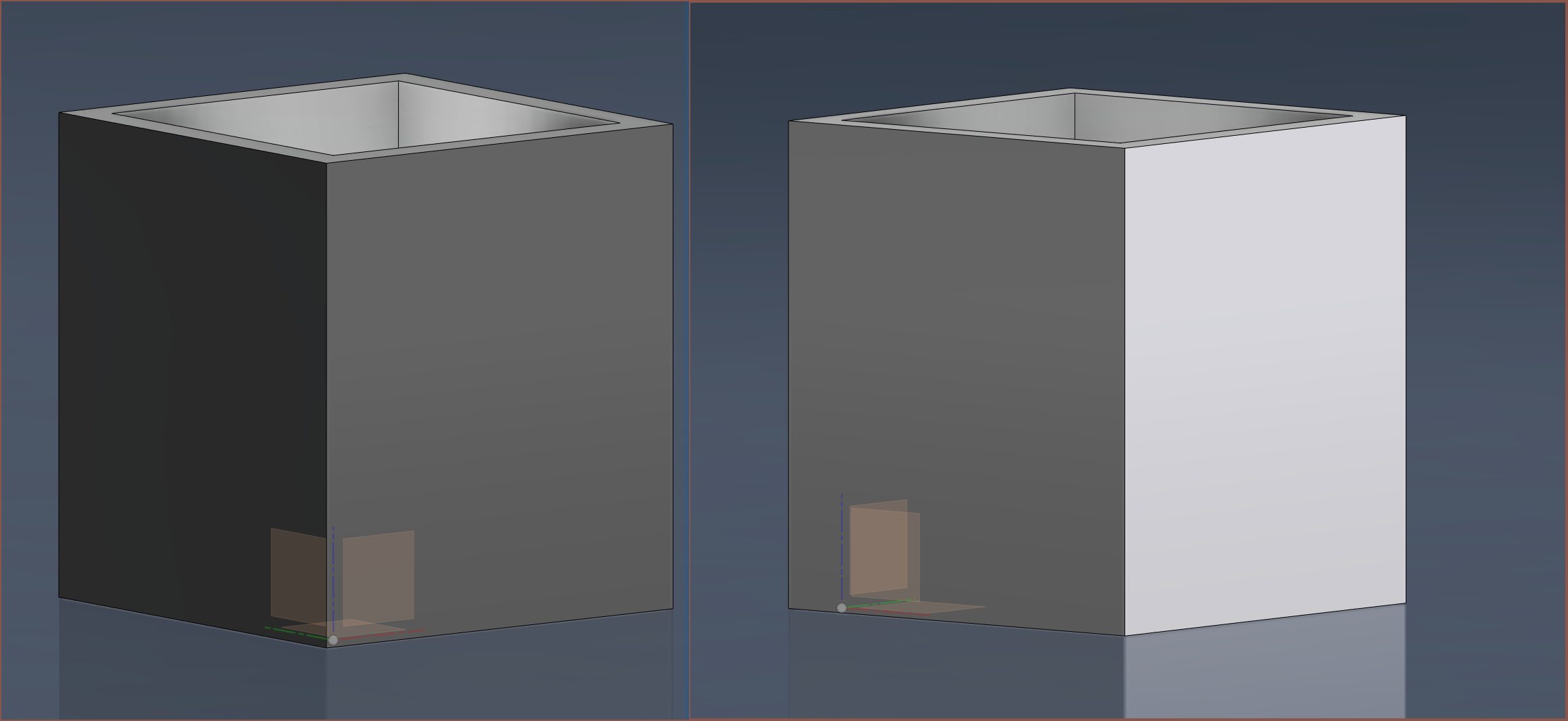
[2024 - Jan 13] I found out that the yellow and red inputs heinz used were for the mixing inputs. Thus, the actual view likely looks more similar to the diagram with the 2 inputs, such as a squircle instead of an oval. An idea I had after seeing the video was the below design from this video:
I feel that something like this could reduce the pressure differences caused by material emerging from the inlets.
Ideally, only one or two inlets (as shown above) would be needed, but I can imagine that 3 would be the ideal number
3] The mixing is buffered, allowing for faster changes without needing a small volume
This is similar in principle to how the Pallet 3 splices material before it goes into the hotend, I believe this hotend does something similar within the hotend:
As you might already be able to see, this ties in with my next hypothesis point:
4] The diffuse distance is short
As it has been seen from typical N-in 1-out hotends, one angle of the finished print is predominantly one colour and another angle is predominantly a different colour. Heinz has also looked into using this phenomenon for multi-colour prints with a rotating nozzle.
The angle where the colours blend the best is actually the middle of these two angles. This is also where the two materials contact. What this hotend does is take this thin strip where the different materials meet and revolves it around the outer surface. The colour of a material is typically only seen from light reflected from the surface of it, and the depth increases the more transparent the material is, so this is ideal.
-
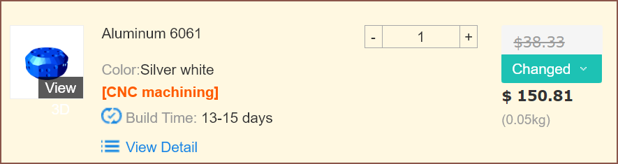
[A] Mystery CNC Price Hike
06/08/2023 at 08:52 • 0 commentsI can only imagine that part of it is because I haven't provided a tech drawing (I wanted to see the price without threads) and part of it because of the filleted internal grooves, but even in the ideal case it'll probably still be >$20 more than the threadless 3D printing option. Or maybe this part is harder to make in aluminium instead of brass?
It sure sounds like the second attempt is going to be a 3D print, though I need to be able to avoid the $30 thread cost without the nozzle / heatbreaks leaking. I might just see if I can 3D print the bottoming M6 threads and then all I'd have to do is simply tap 3 M3 holes. I might model in 2 holes for each cartridge so that there's a spare one if I have trouble tapping the first one.
Additionally, I'd need to change the geometry of the internal channels to ensure that they actually print properly. 1mm diamond square, anyone? The height of the block is likely to be near 30mm but it's better to be conservative when I'm not a company with a fat R+D budget.
-
[T] An Insert Like The Positron Hotend?
06/02/2023 at 19:03 • 0 commentsThe Positron V3 uses the heater cartridge as a dowel pin to prevent the brass insert from falling out. Then the heatbreak screws in and bottoms out on the side face and the nozzle bottoms out on the top face of the insert.
I'm wondering if something similar could be done for the corners of the trangle material path. I can't think of anything at the moment that's not even larger than the 40mm edition in the previous log, and I fear that PCBWay would charge for every sperate entity.
-
[M] M4 Grub + 2mm Ball Edition
06/02/2023 at 18:50 • 0 commentsLooks kind of alien... I still remember asking myself seeing...
...and being like "Ok, you've done that... but y tho?".
Now I've come to the same conclusion. I'm planning for a 2mm ball though. Maybe even 1.5mm, if I'm safe to assume that E3D is using a 2.5mm bearing to plug a 2mm channel. (I'm using 1mm channels)
The nice thing is that the threads at the bottom of the blind hole no longer need to exist, so I can let 2 holes slightly cut into each other. There's at least 3.5mm of thread space, the outer diamter is now 40mm with 37mm across flats. The mass of the block is now 50g, up from 39g.
-
[X] Looking at the state of the grub screws.
06/02/2023 at 17:16 • 0 commentsFor the single M3 grub screw that actually went all the way in, it looked fine.
For all the other ones tho...
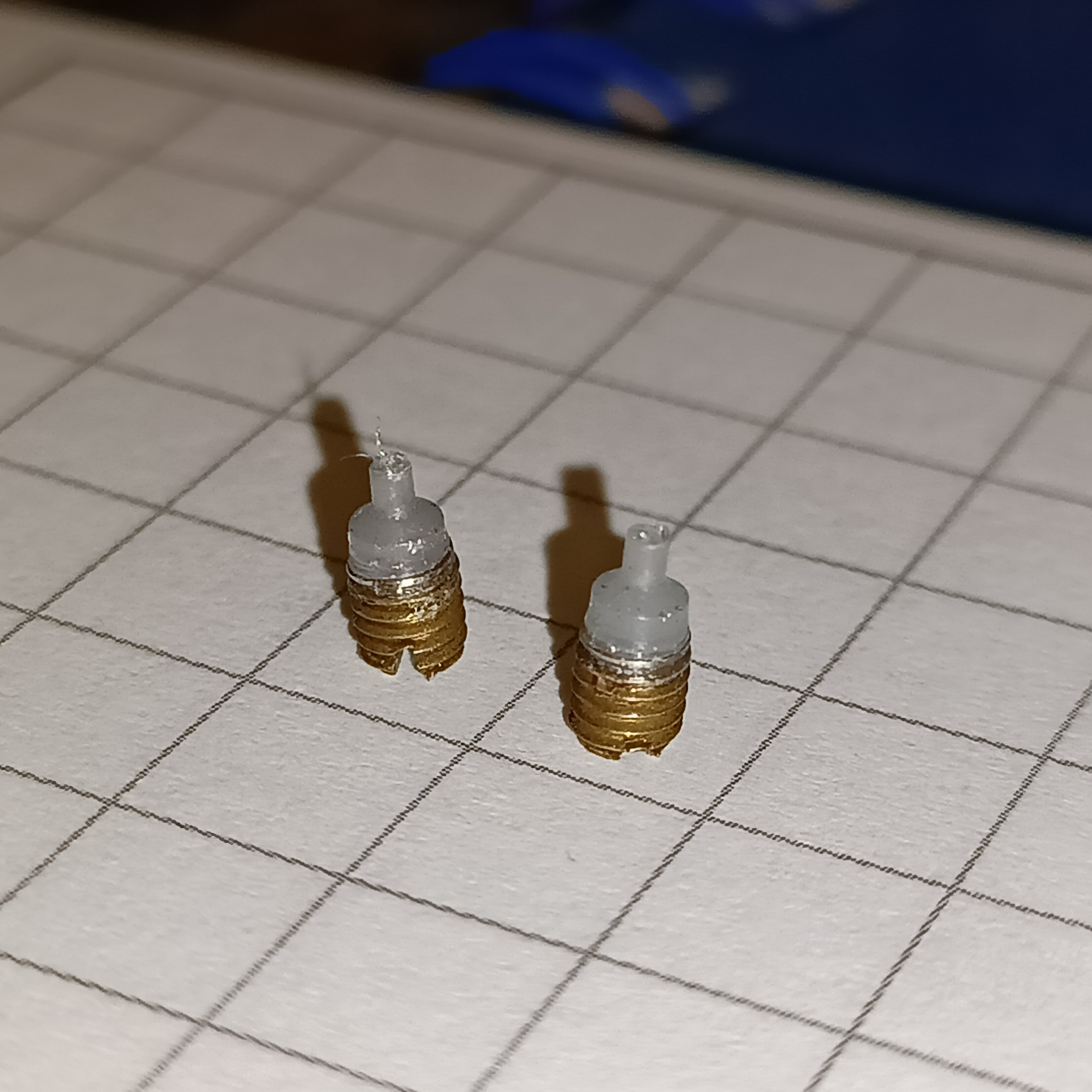
Some screwed out with plastic:
Some screwed out with plastic remaining in the hole:
Dark greyish PETG in the left and what looks to be cleaning material in the right hole. And some didn't budge at all and it looked like I could risk breaking the M3.
I'm thinking that the small size of M3's are unsuitable for this kind of work. I'd imagine that M4's would be more reliable, and they certainly can handle more torque. The hex M4 grubs that hold the heatsinks seem sturdy enough.
-
[X] No immediate leaks!
06/02/2023 at 15:41 • 0 comments[X] = Experiment / Test
I wake up.
It's 9am.
I think "If I test the hotend now, I might be able to make it to the uni if things go wrong."
It took 6 hours, with the first 3 hours just finding my seldom used soldering gear because the thermistor I have wasn't pre-soldered to the included dupont connector. It's not like Trianglelab's CHC that conveniently had everything ready to go.
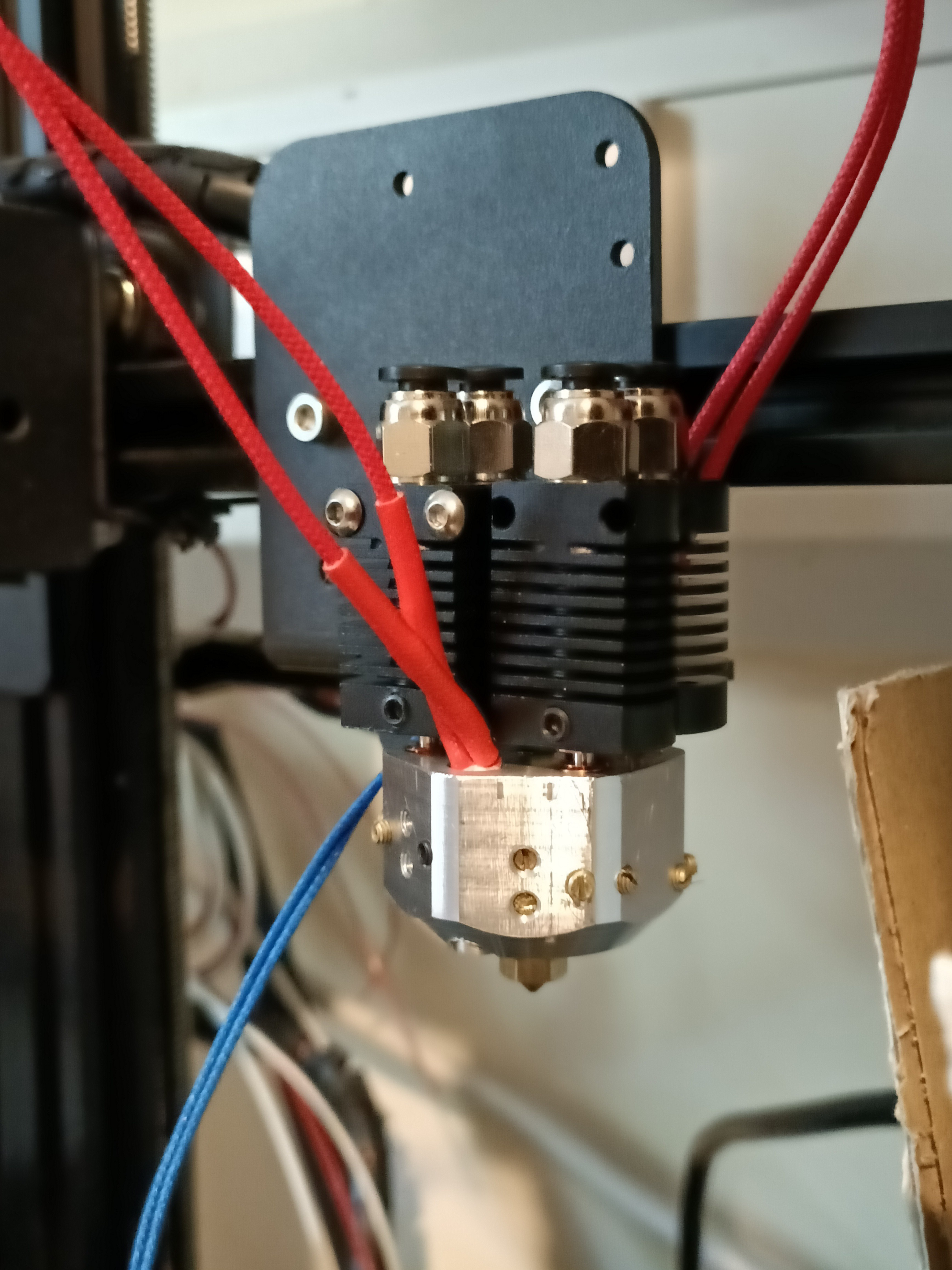
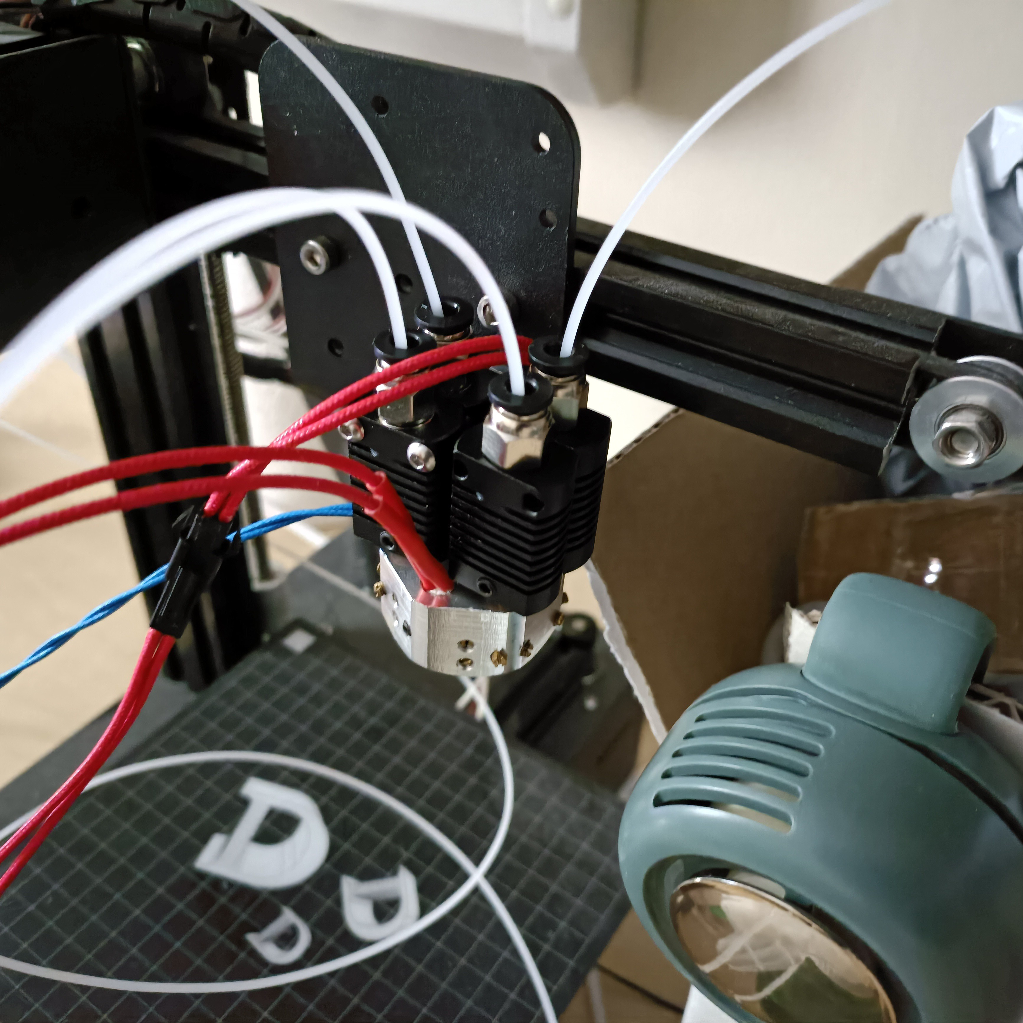
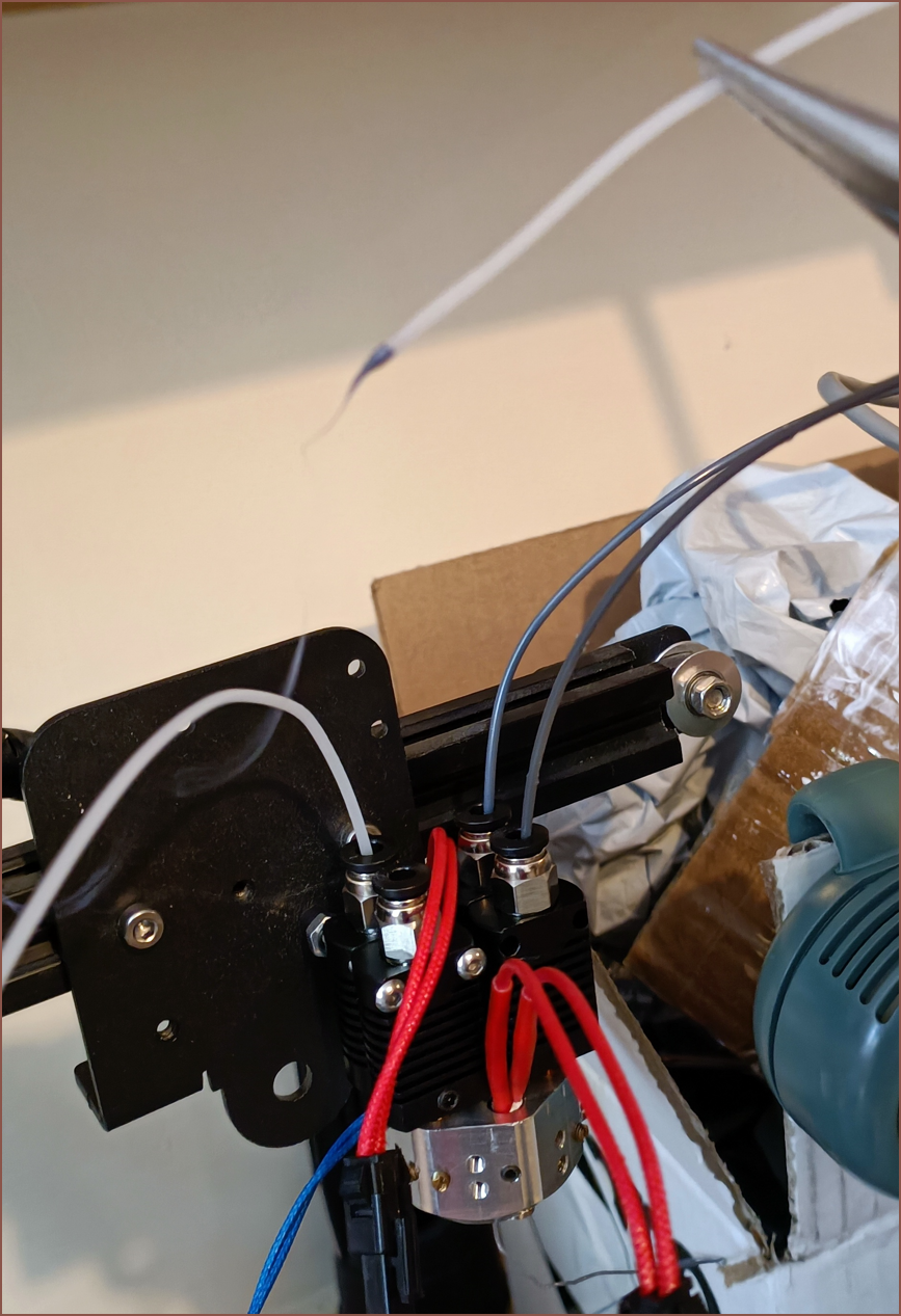
I found the CR10 mounting plate intended for the #Revolving Hotend [gd0012] and used that to mount the Coaxial Hotend on the currently unused DP2 printer, just like the last time.
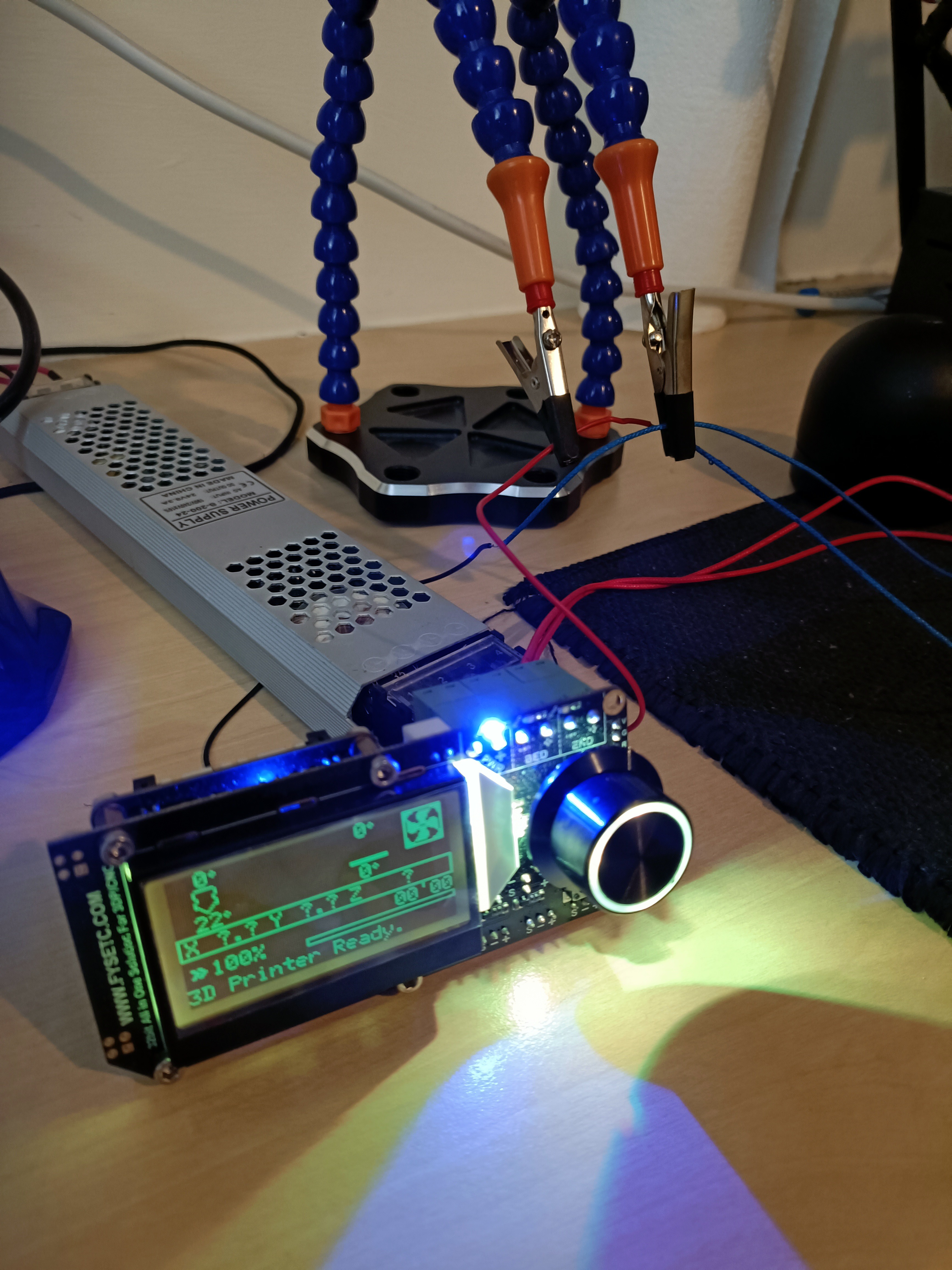
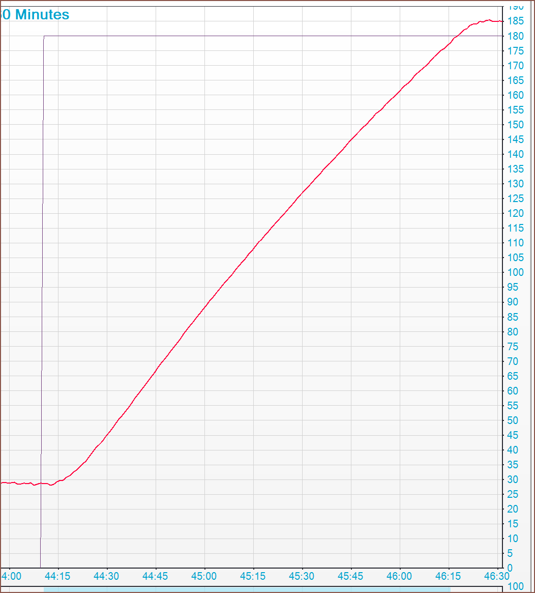
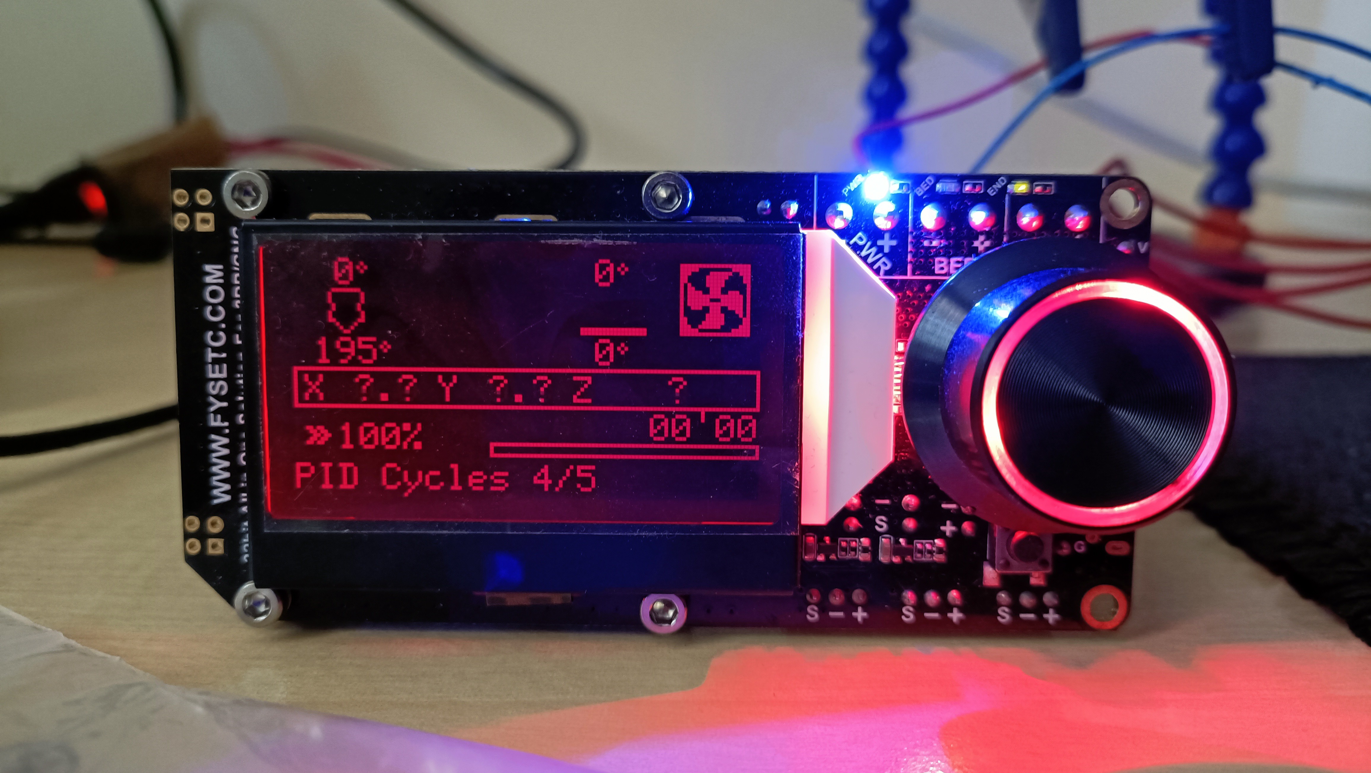
I got my FysetC AIO out and the firmware is conveniently already configured to the correct thermistor. I started a PID tune, but the temperature climbed really slowly when only a single 40W cartridge was powering the hotend.
Since 80W at 24V is 3.33A and the AIO is good to 5A, I plugged in the second cartridge and now the temperature was increasing at a standard rate.
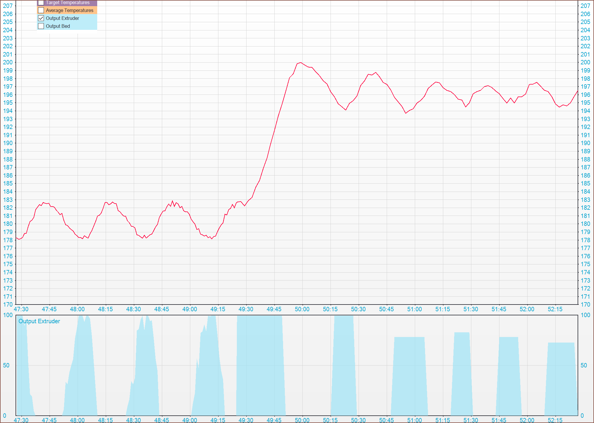
Usually, the auto PID swings around the target (in this case 196) by a couple of degrees, but this time it only differed by +/- 1 degree. I can only assume it's because there's a lot more thermal mass than for a typical hotend.
The first PID was rather poor so I ran it again, starting from 180C not room temp.
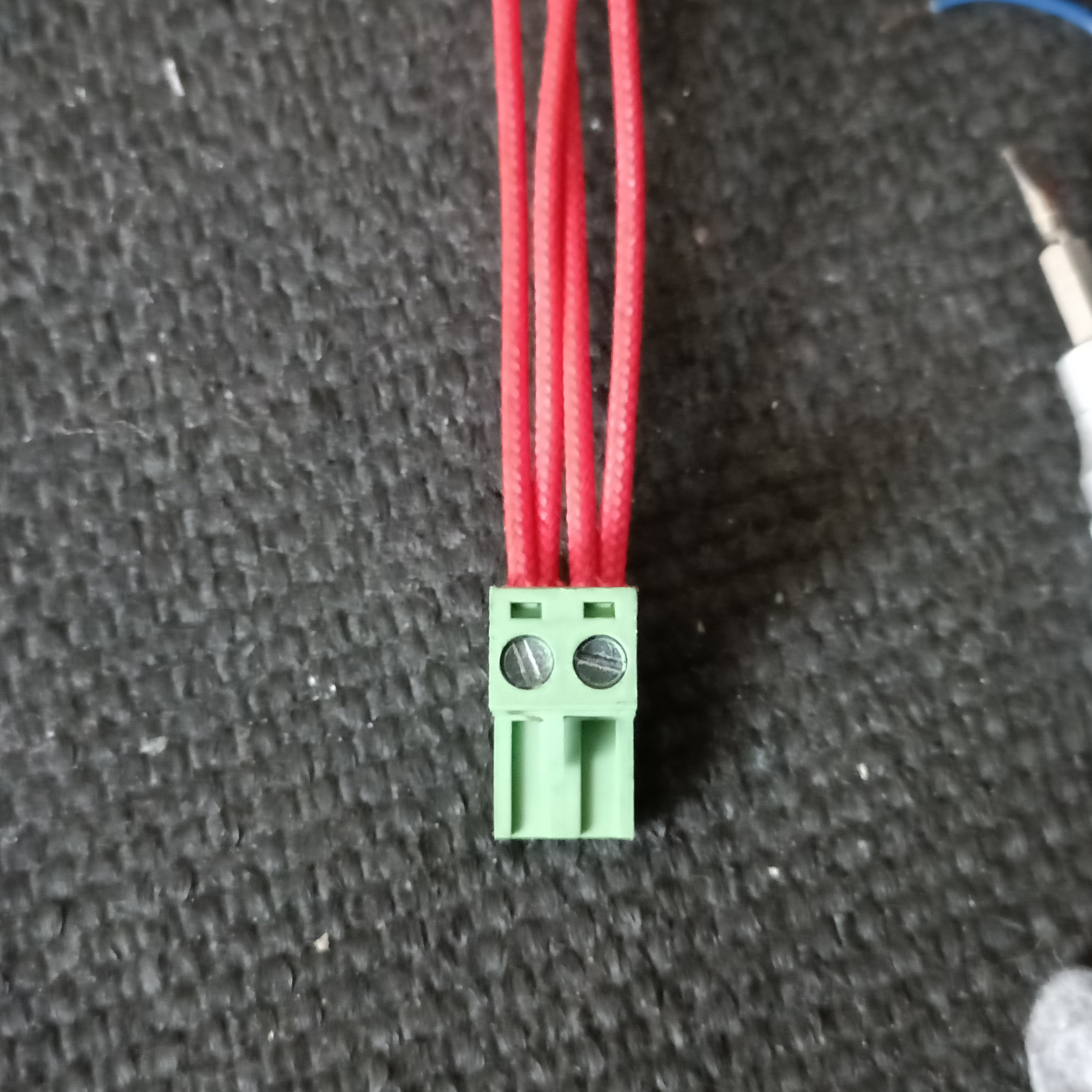
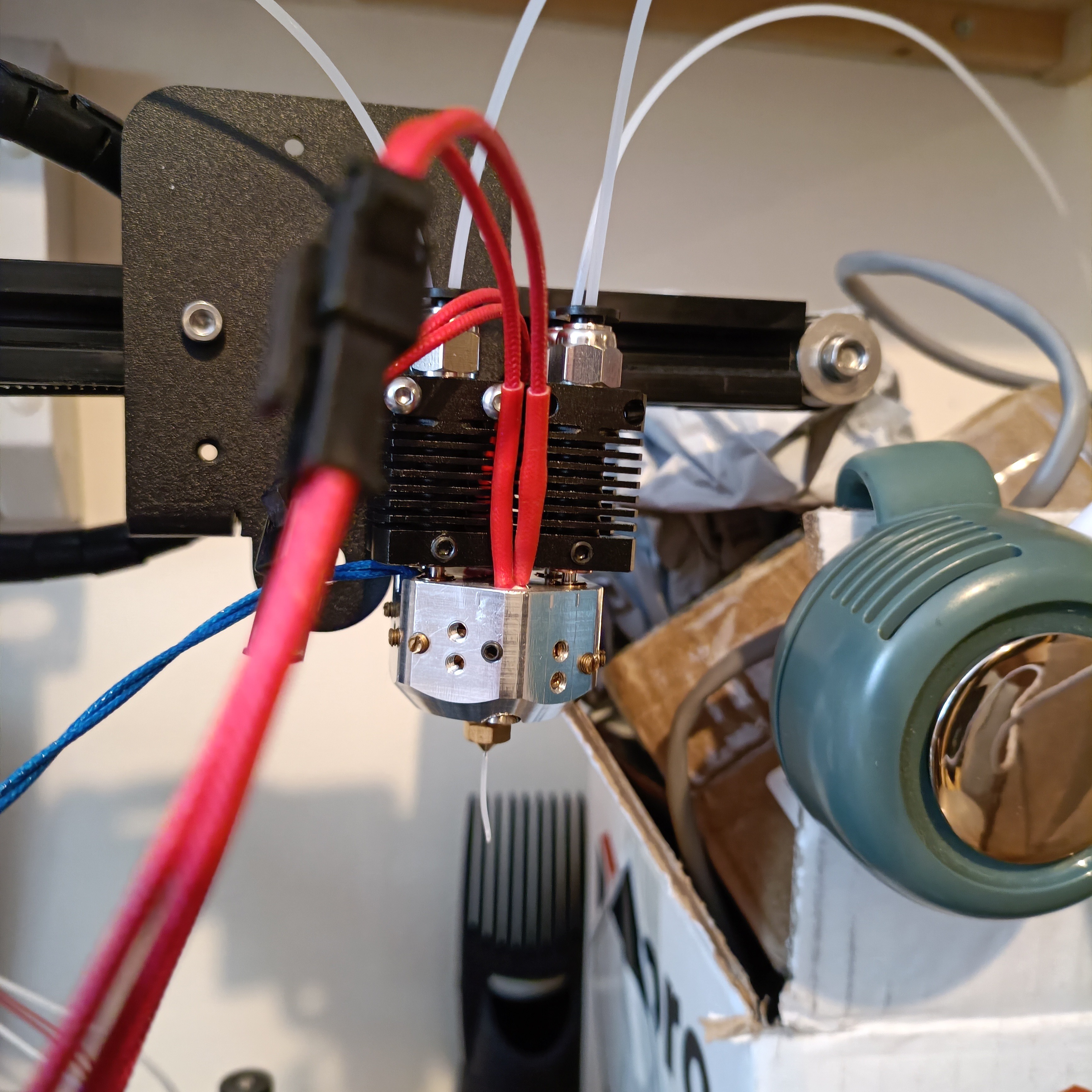
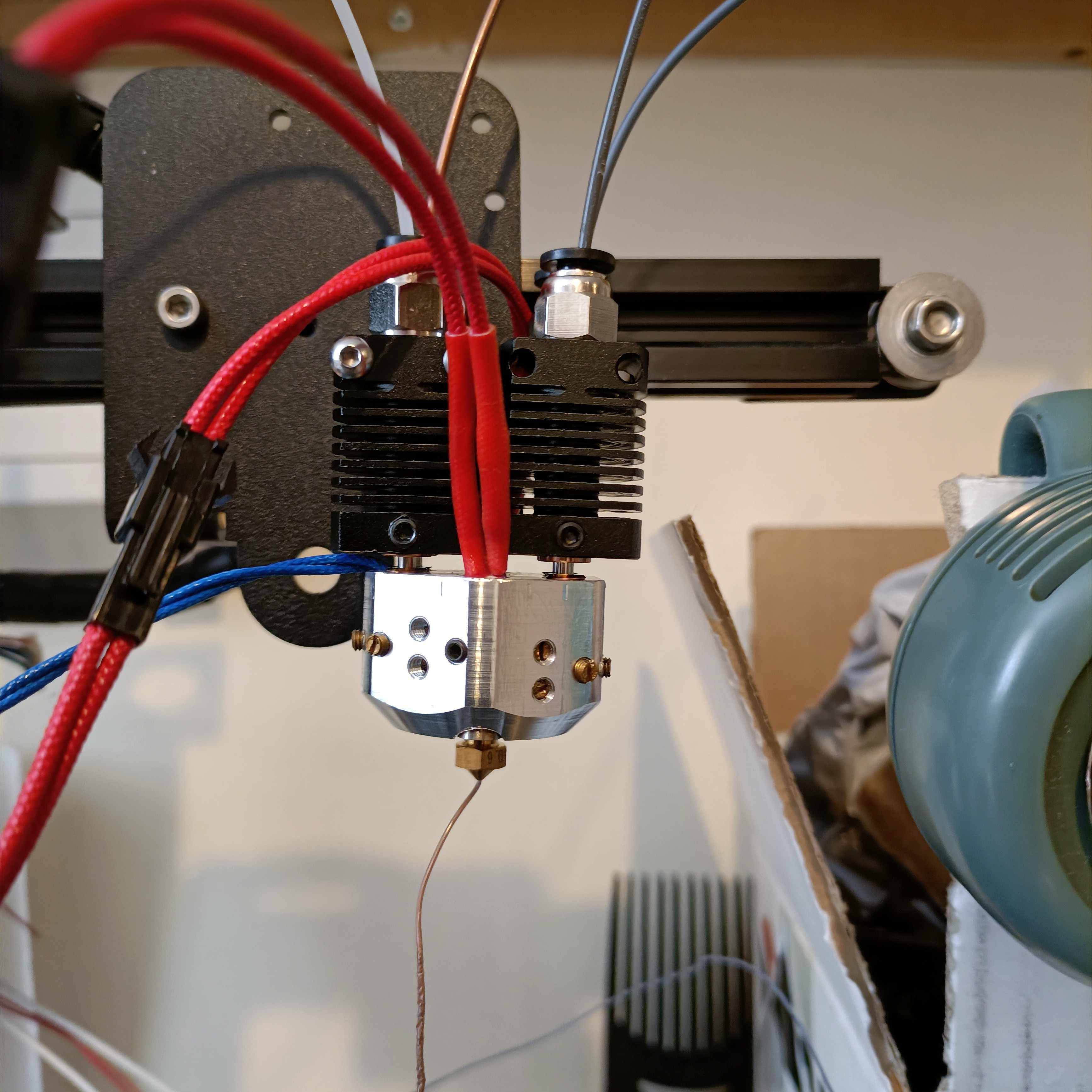
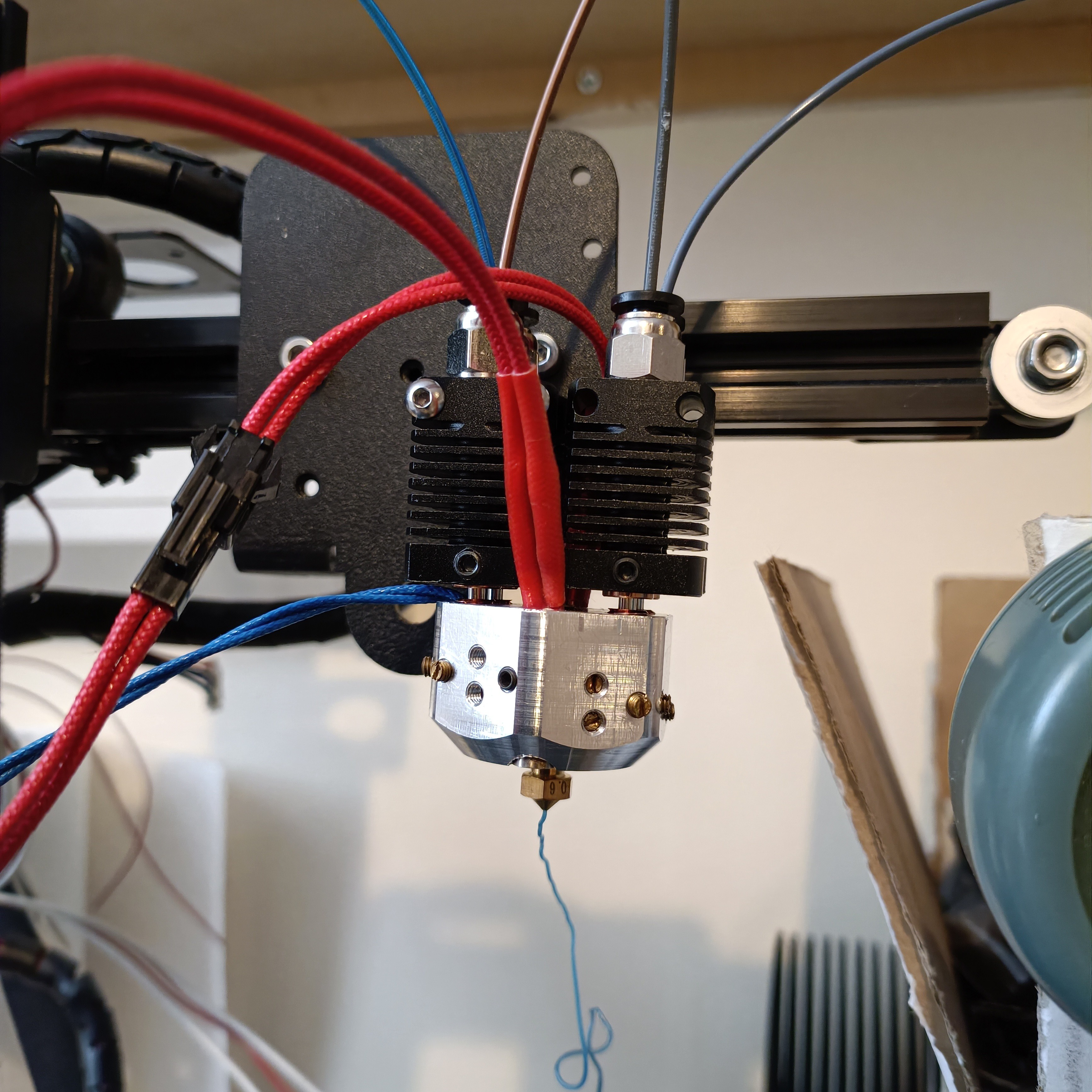
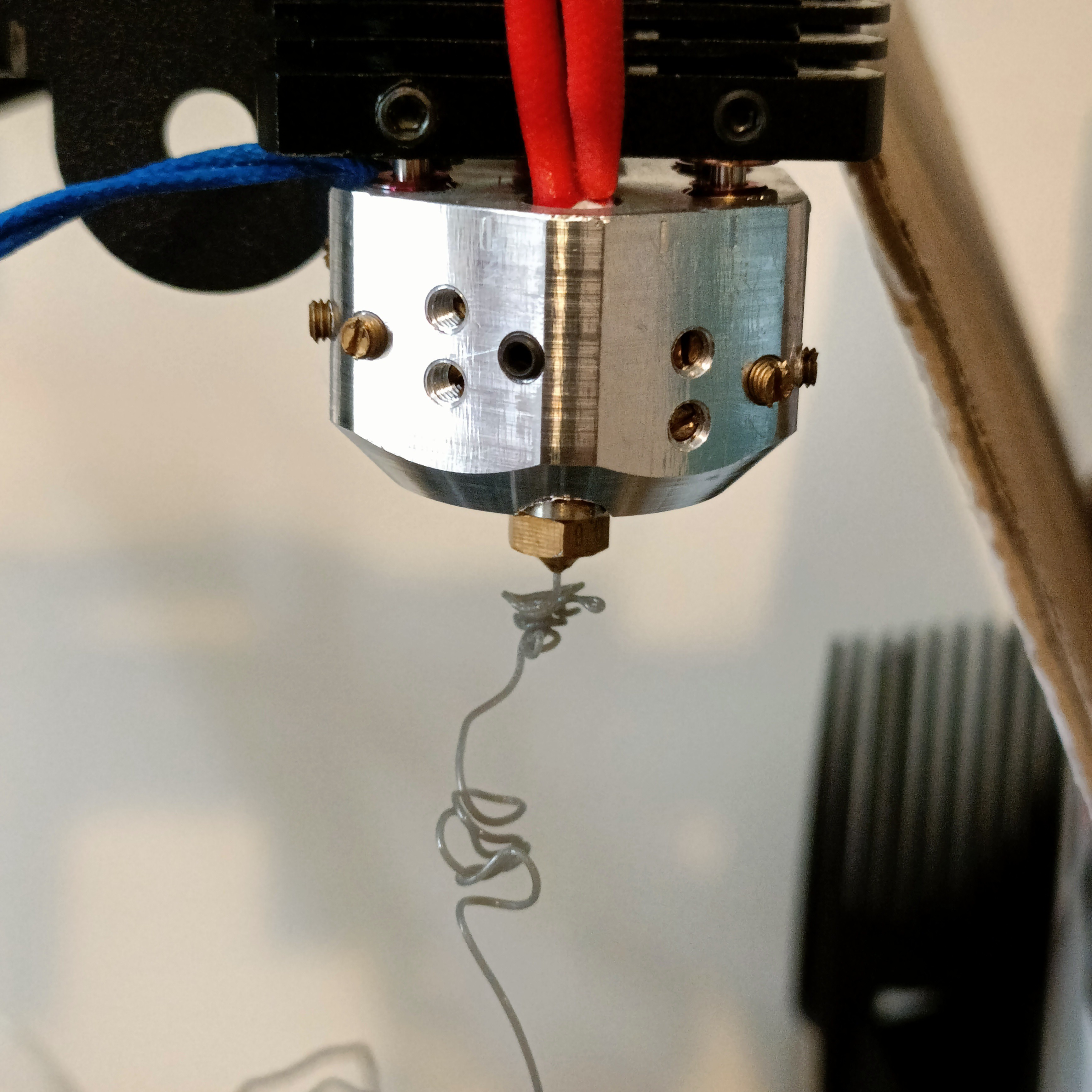
That green cylinder is a battery powered blower fan. So the first thing was to purge with cleaning filament. It took a while, but I eventually saw something actually poke out the nozzle! (image below)
This was me running the hotend at 200C because 180C was kind of tough. I'm also starting to think I've just bought a lifetime supply of cleaning filament because I've still got loads left.
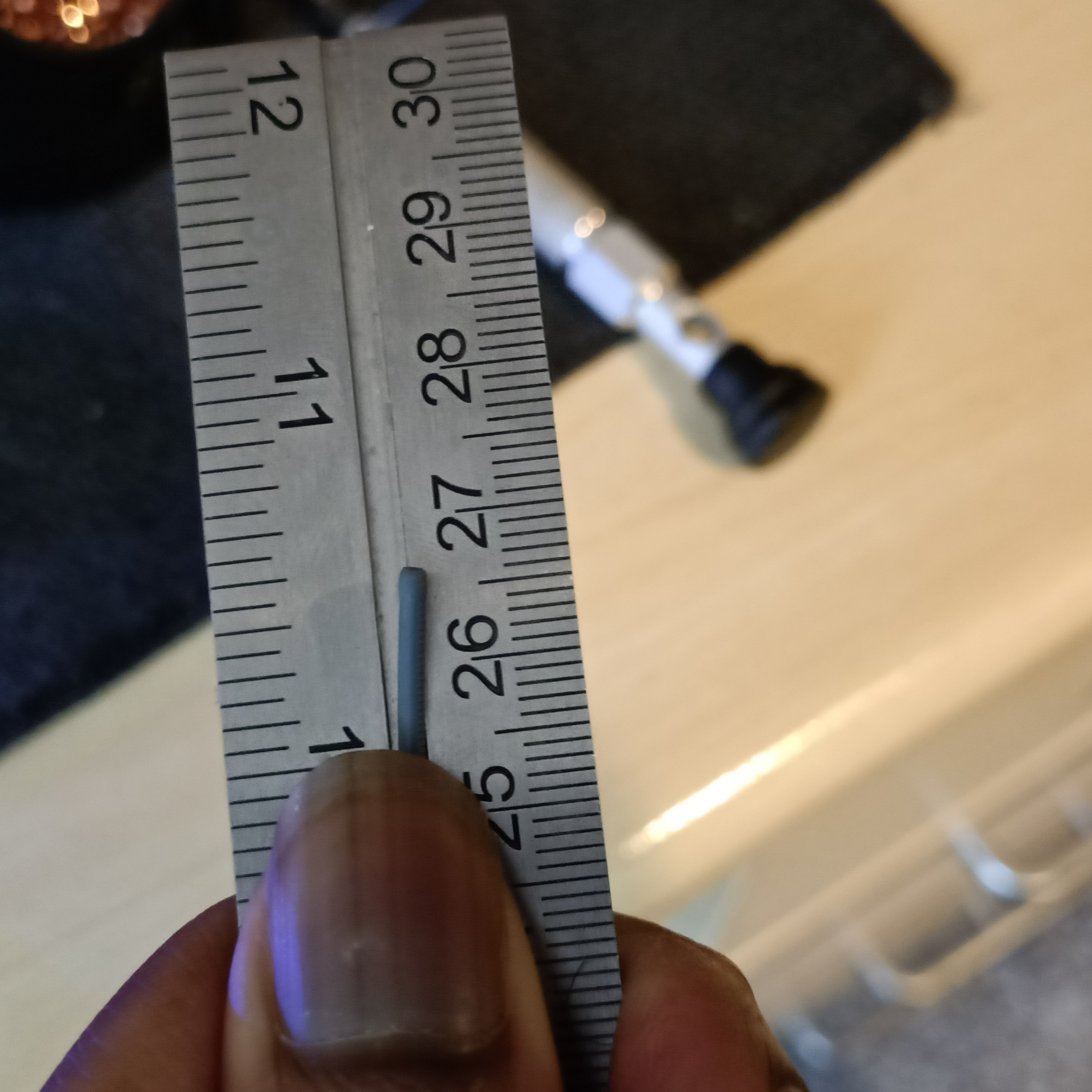
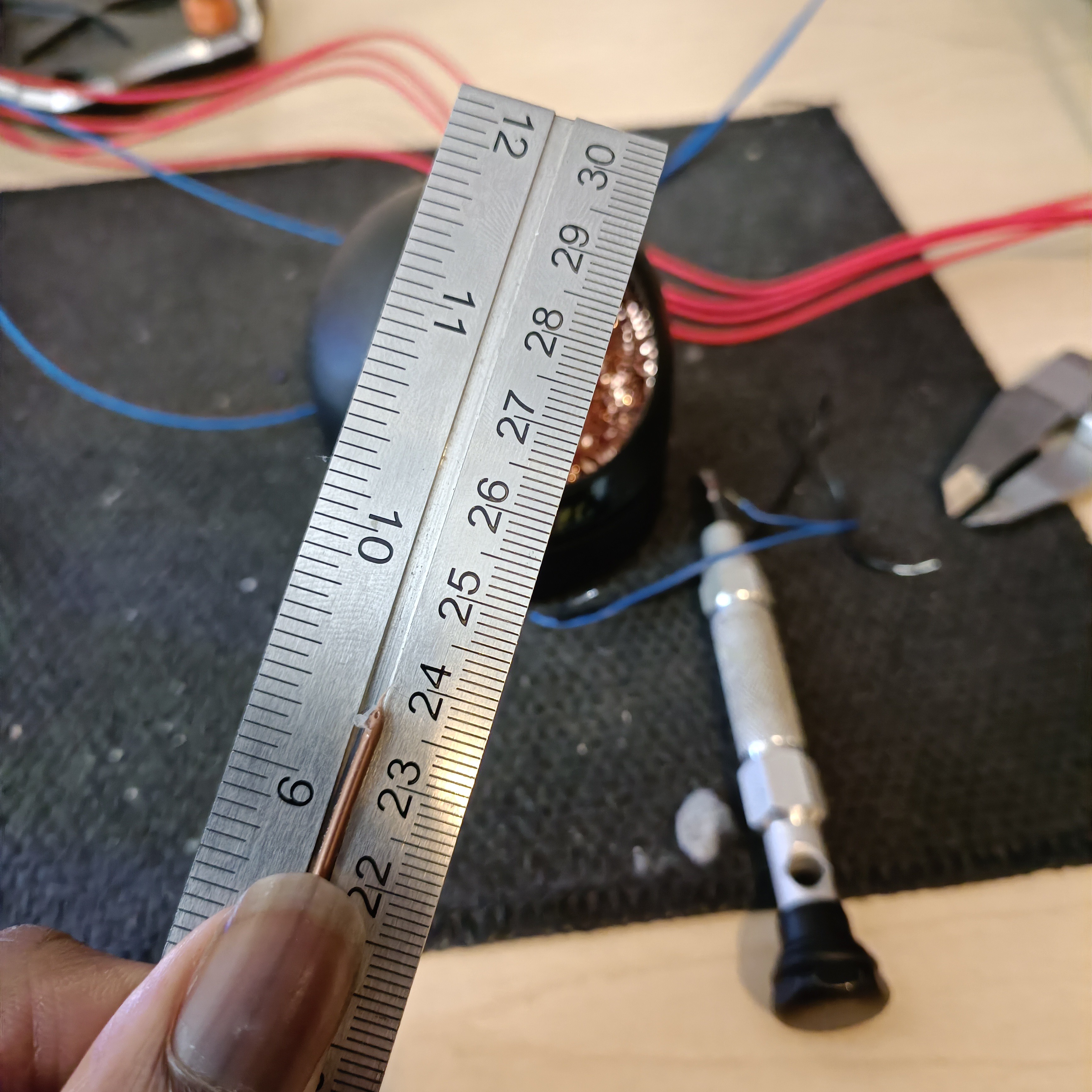
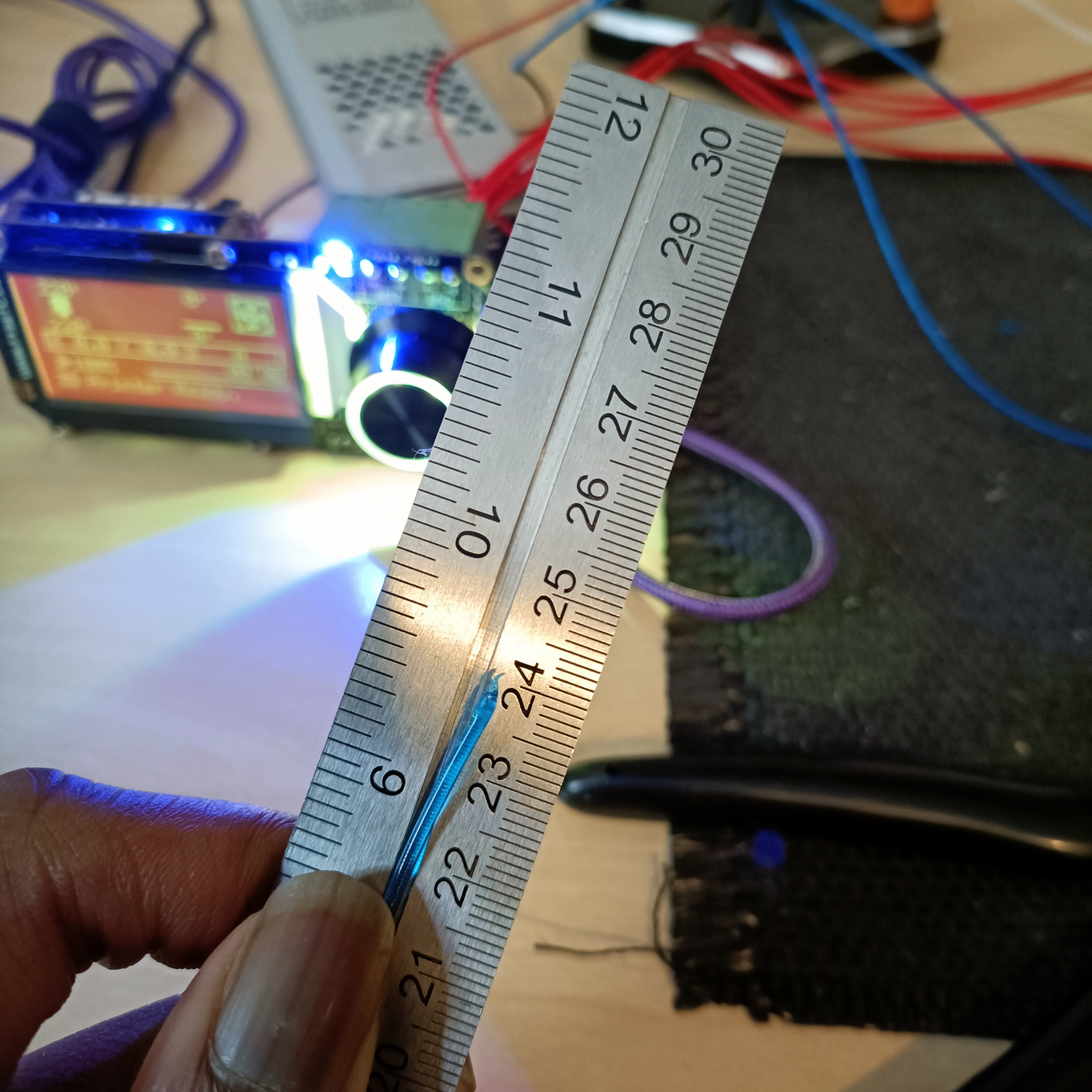
I put in some PLA to try extruding it, but then I worried about the fact that PLA clogs easier than other materials for all-metal heatbreaks and switched to PETG instead. Before I did that, I cut of precisely 1 ruler length (305mm) of material to see how much I needed for the colour change.
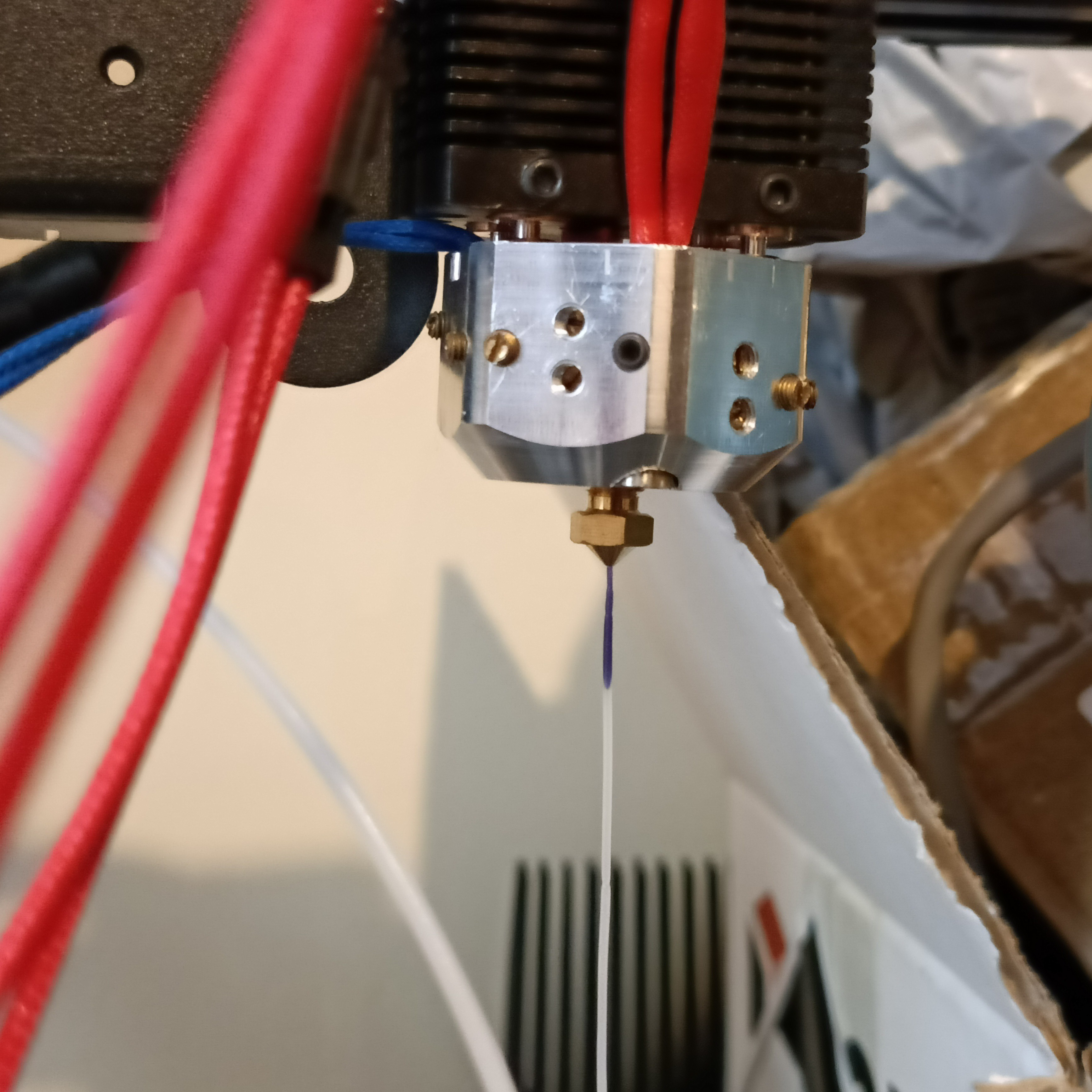
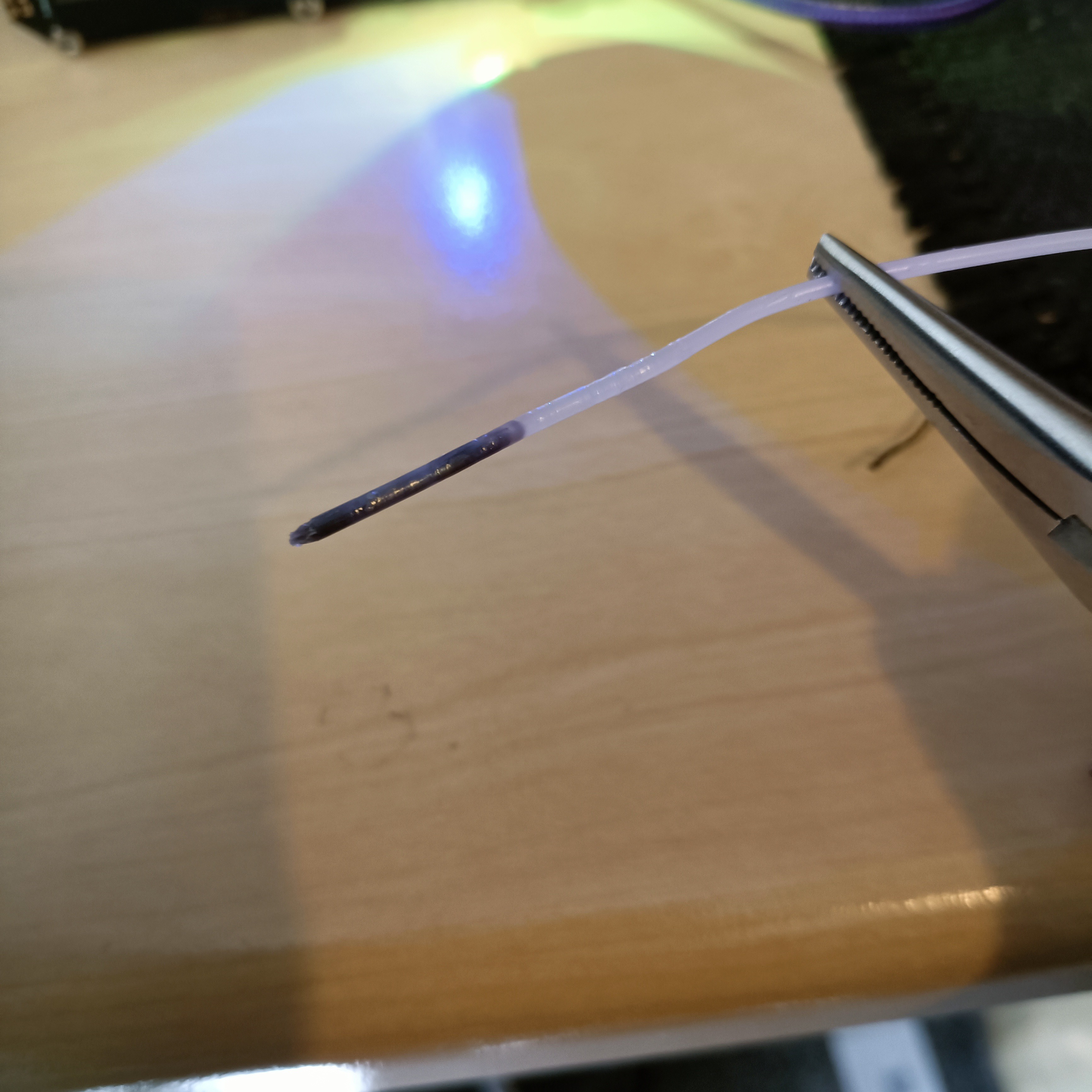
The first change was rather sharp. That's the dark blue PLA I used before switching to the "Solid Grey" PETG.
This was the first, but since I already started with some PLA beforehand, it's probably not accurate.
I didn't do the length test for the Dark Grey PETG I put in next because it's so similar to the Sold Grey in colour. I'm starting from the lowest filament path and progressively going upwards. Interestingly enough, some material still got to the next cleaning filament input.
The next filament I put in was the extremely wet copper filament, and it didn't take long to see it's identifying bubbliness though the nozzle.
The last input looked like this. I then realised that the pressure inside the hotend is probably pushing up the other inputs since there's nothing actually holding them in place. Thus, when I was extruding one filament, I was periodically extruding a tiny bit of the other 3.
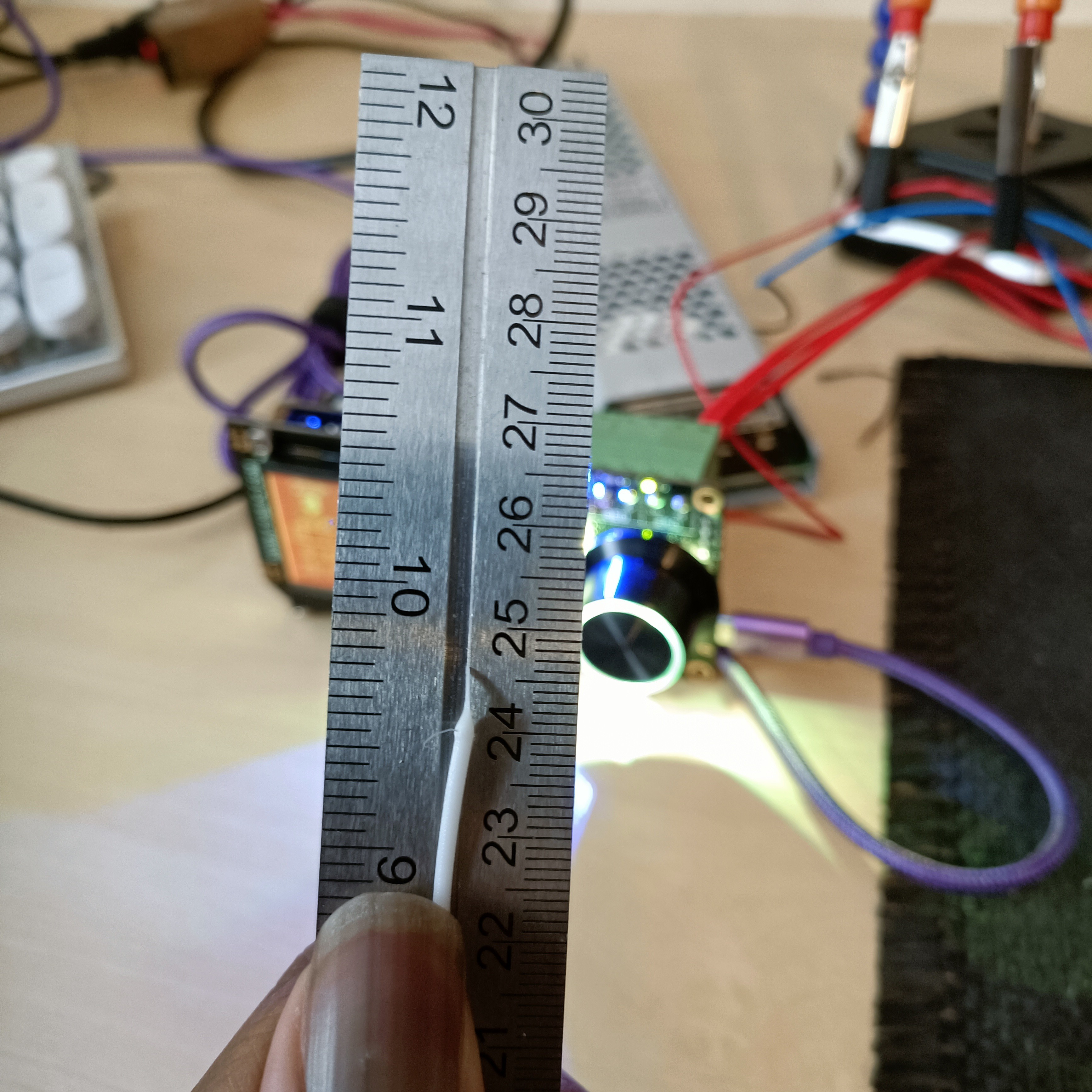
I'm starting to think 24cm is the magic number. It means that 6.5cm of filament needs to be purged for a colour change.
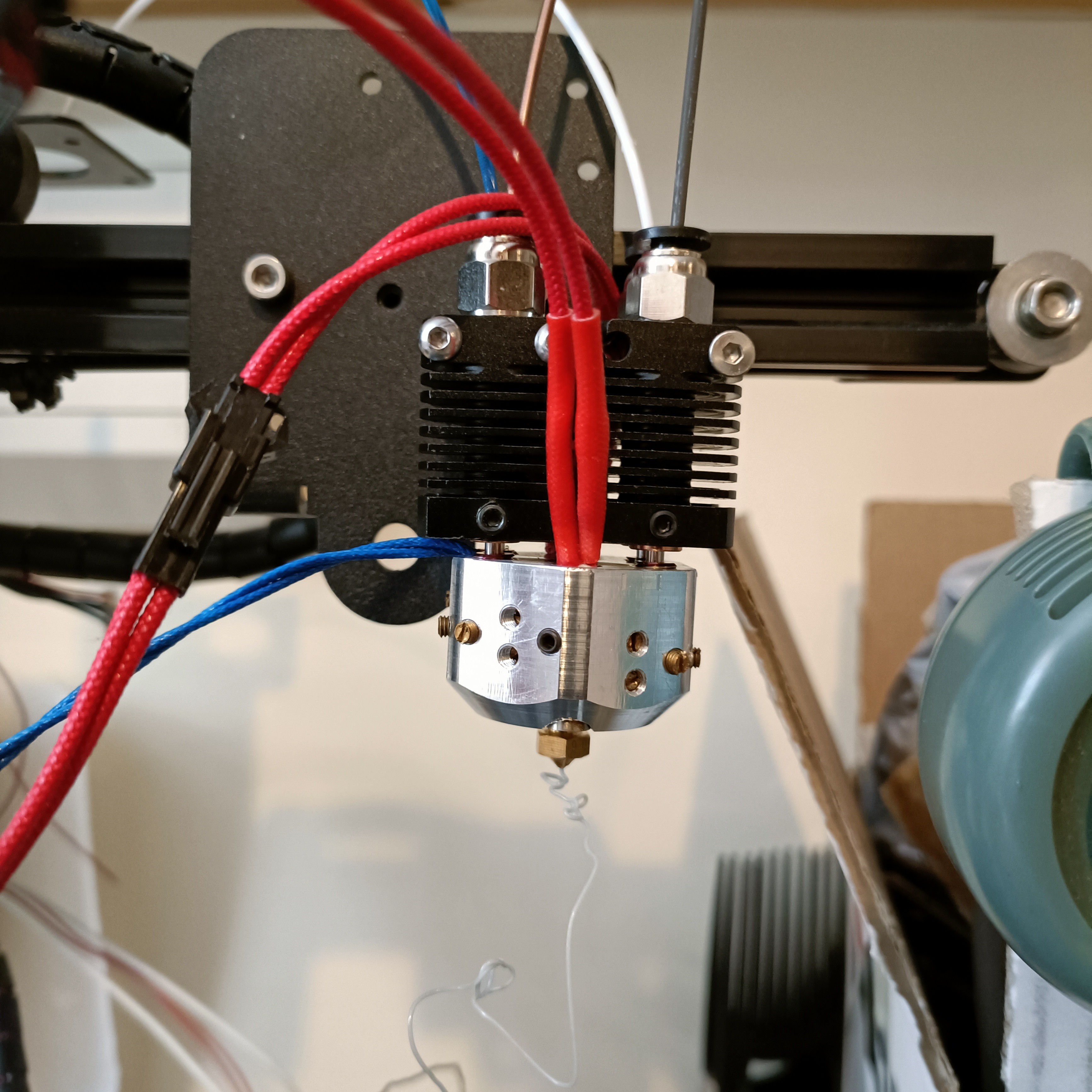
This is white... ish. It seemed off-white when it came out of the nozzle. I also think it's safe to say that the purge length is 6-7cm.
Lastly, I just wanted to make sure that the grey input was working correctly. Since I've already extruded before, the measurement would be inaccurate.
Conclusions
Perhaps some kind of high-temp Loctite will suffice, but I'm thinking of having a grub screw to prevent the heatbreaks from potentially twisting out of place. I feel like the 2 inputs that weren't mounted have probably loosened, and have precautionally tried to turn the heatsinks in the tightening direction before turning off the heat.
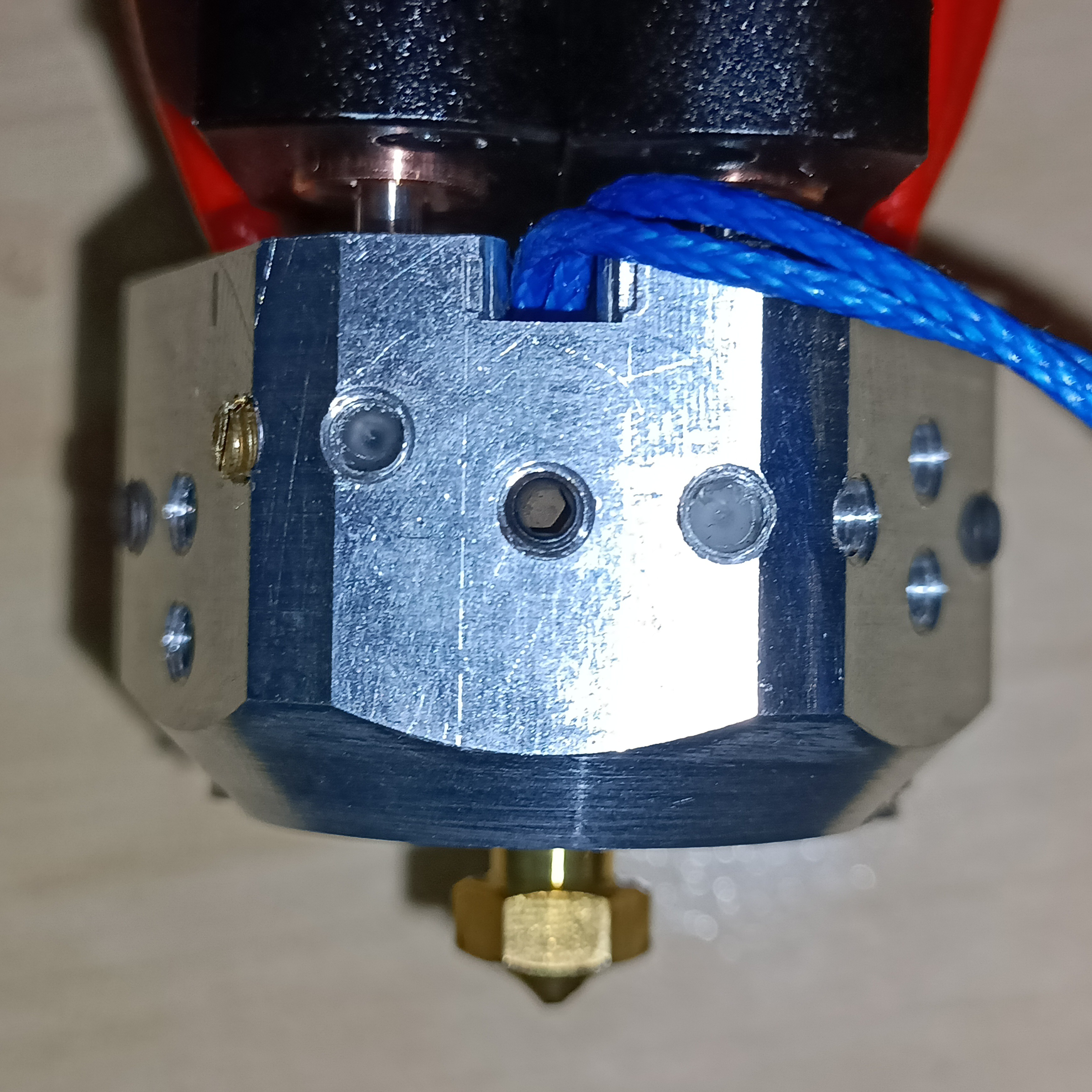
Taking the heatblock off, I havent' seen any signs of leaks yet, though I'd likely need to put in a lot more than the 50cm or so I've done in this test to see that. Just like how SpaceX's main target for their last Starship launch was "it leaves the launchpad", my main target is "Filament actually comes out of the nozzle via all 4 paths, and the hotend is still shiny afterwards".
I'm now taking off what grub screws I can to see the damage report.
-
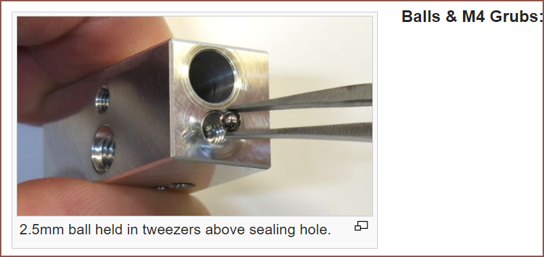
[T] Sealing with 2mm ball bearings?
06/02/2023 at 01:05 • 0 commentsSo I'm now learning about the wide world of thread taps, such as this article or the video below, and I'm thinking "maybe this is the real reason behind E3D choosing to go with a ball to seal the deal?".
The reason why E3D might have opted for a ball between the hole and the grub screw is to avoid the issue which is that taps aren't that great at creating a thread all the way to the bottom of a "blind hole".
The heatblock would need to be a 36mm hex to account for this, along with M3x3mm grub screws.
Coaxial8or [gd0144]
Full-colour FFF? Multi-materials with unparalleled interlayer bond strength? Abrasives without abrasion?
 I've also had to reduce the depth of the heatbreak threads to prevent the topmost grub void from creating holes in the mating face. I've ensured there's at least 1mm of wall thickness.
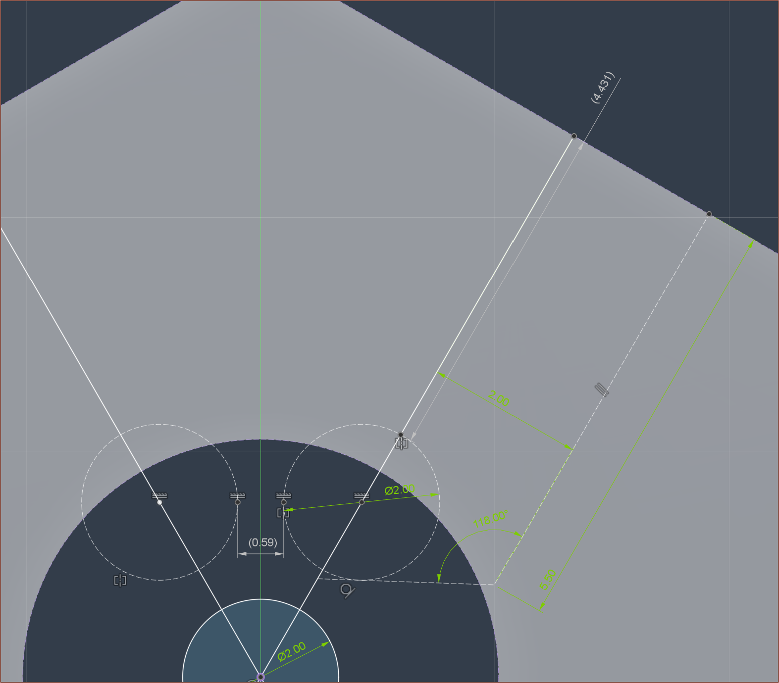 Using a 2mm ball, and a 4mm grub screw, the top of the screw should be just-about below the surface. It might be better to use a 2.5mm bearing to be even closer to the exact length.
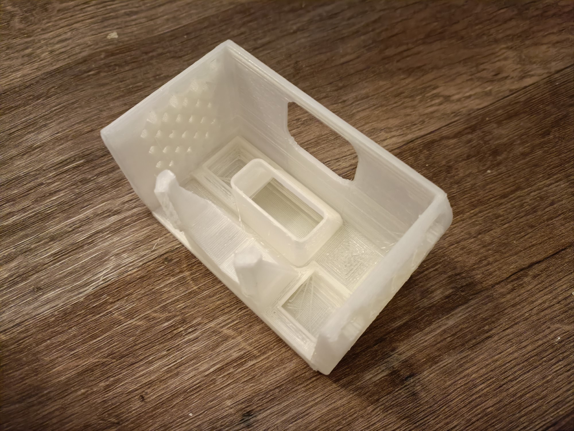


 Lastly, I just wanted to make sure that the grey input was working correctly. Since I've already extruded before, the measurement would be inaccurate.