-
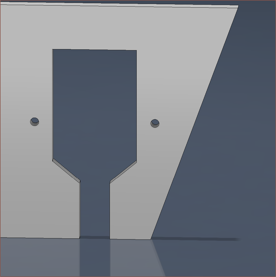
[M] 2D plate drawings
02/12/2024 at 09:00 • 0 commentsDrawings
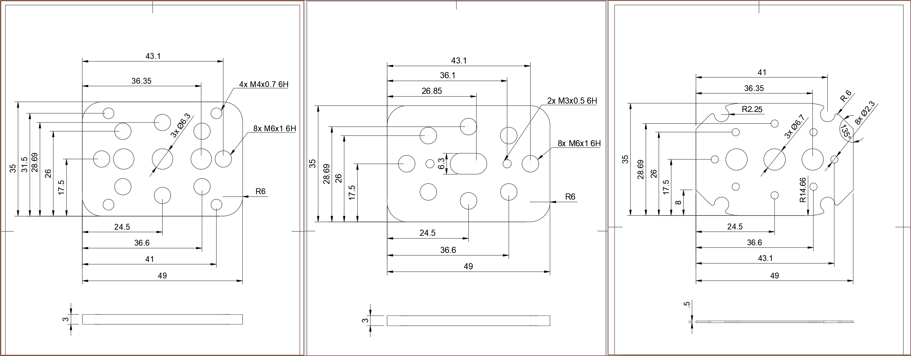
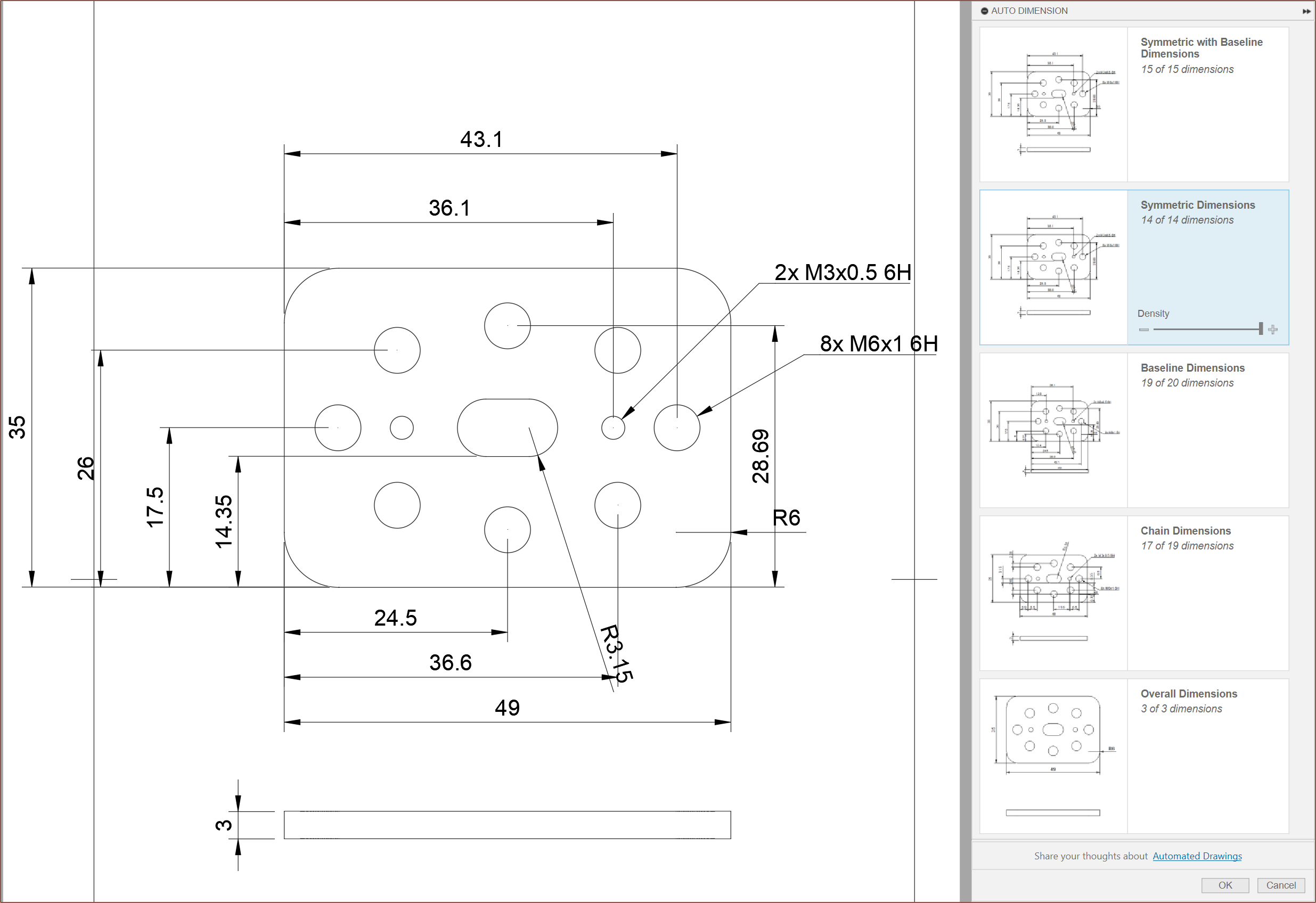
So, firstly, I've dimensioned up the parts. Well, Autodesk Fusion (no-longer)360 did most of it, as there's a nifty "auto dimension" tool:
I now know how symmetric designs are dimensioned.
-
[M] Slim Cover and Hotend Holder
02/11/2024 at 13:22 • 0 commentsI've spent over 4.5 hours to get to this point.
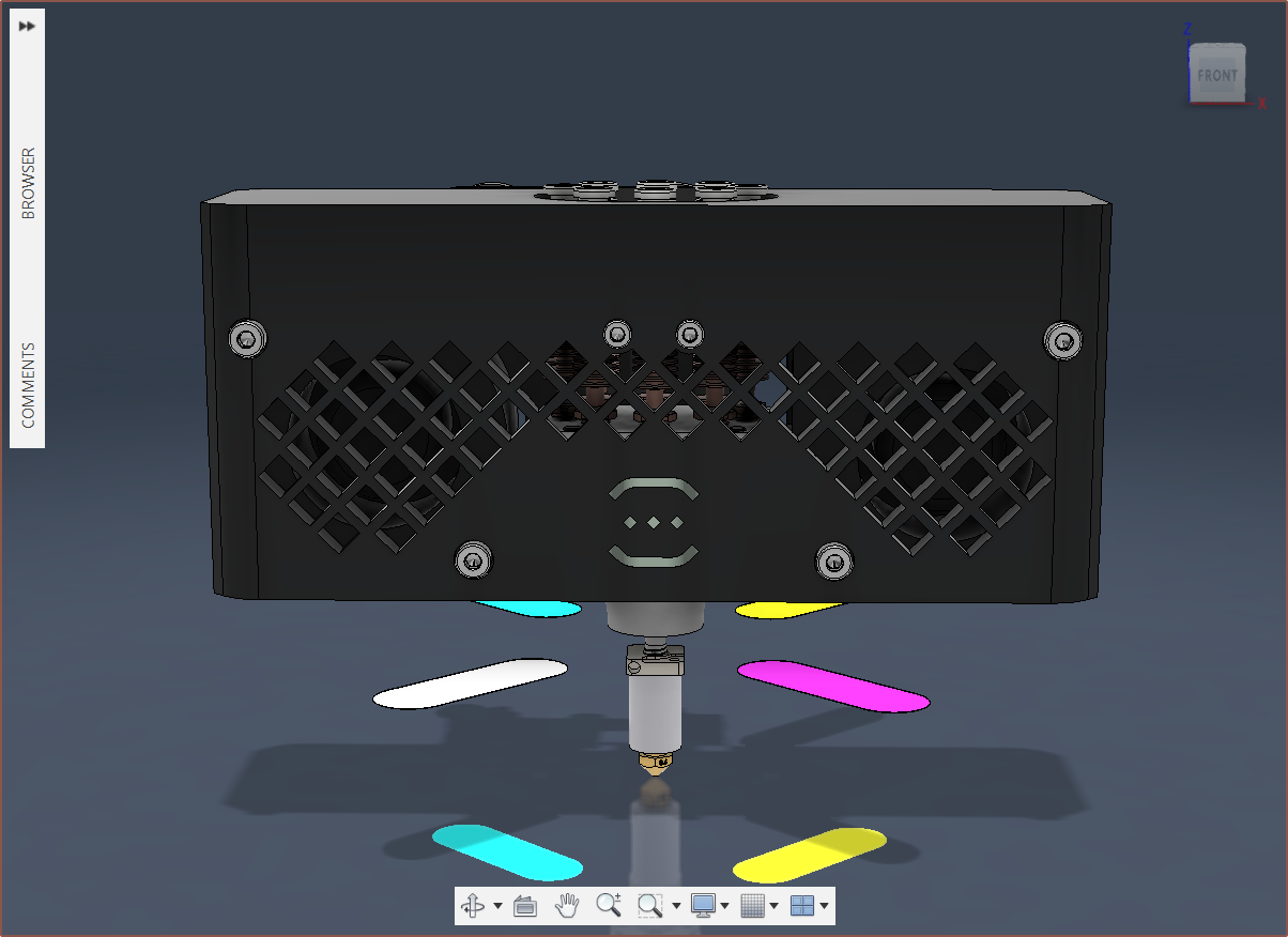
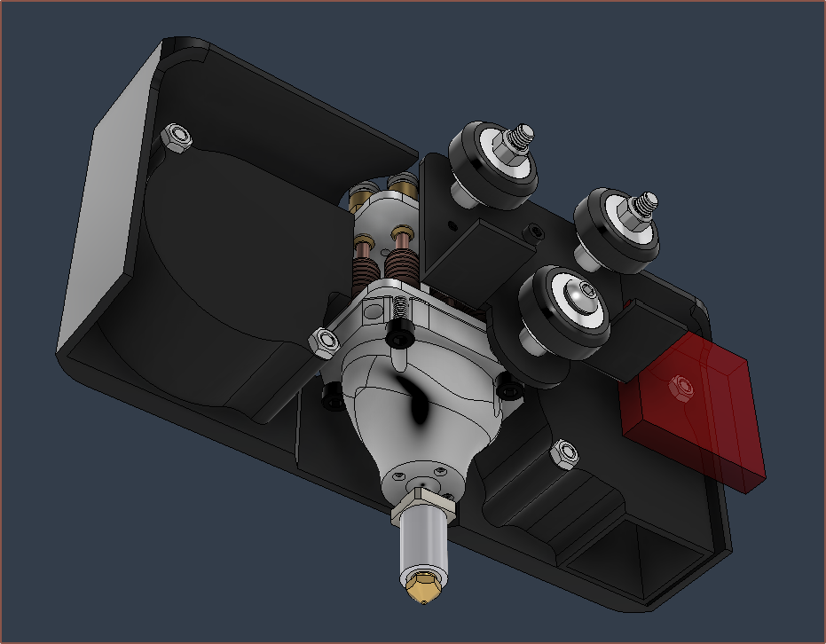
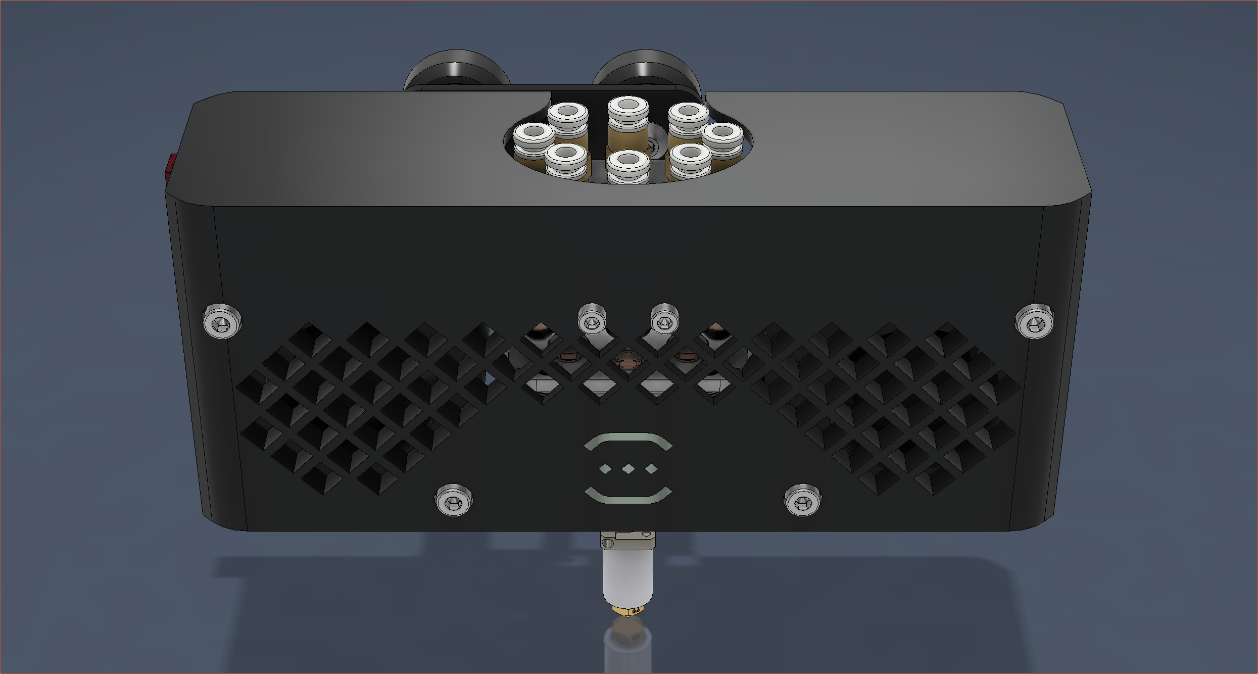
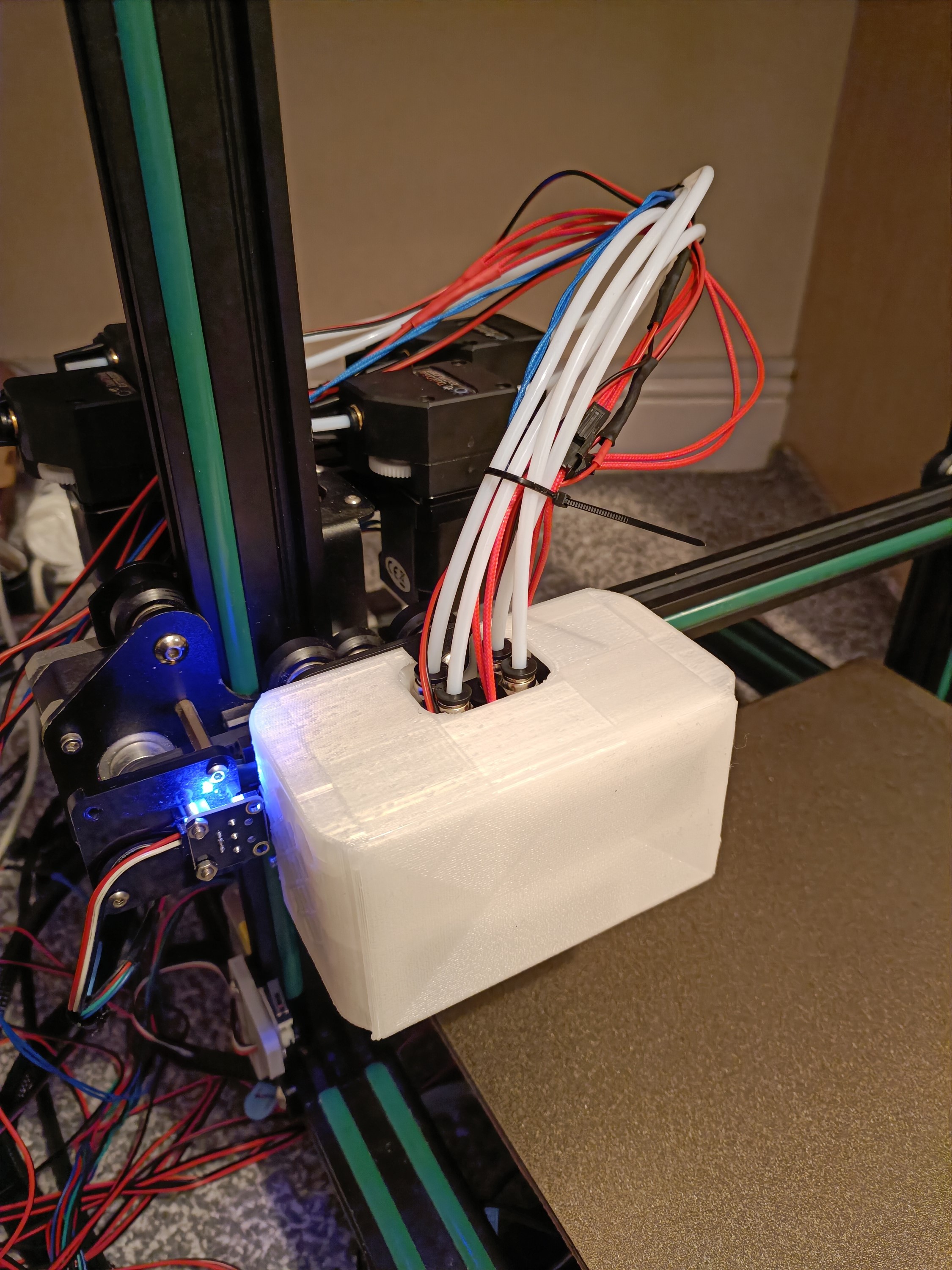
Essentially, I determined that the hotend cover would be more streamlined and the air paths would be more optimal if I placed the 6028s like so:
That red square is the X-axis endstop which I didn't account for when I made the 4-in-1-out cover.
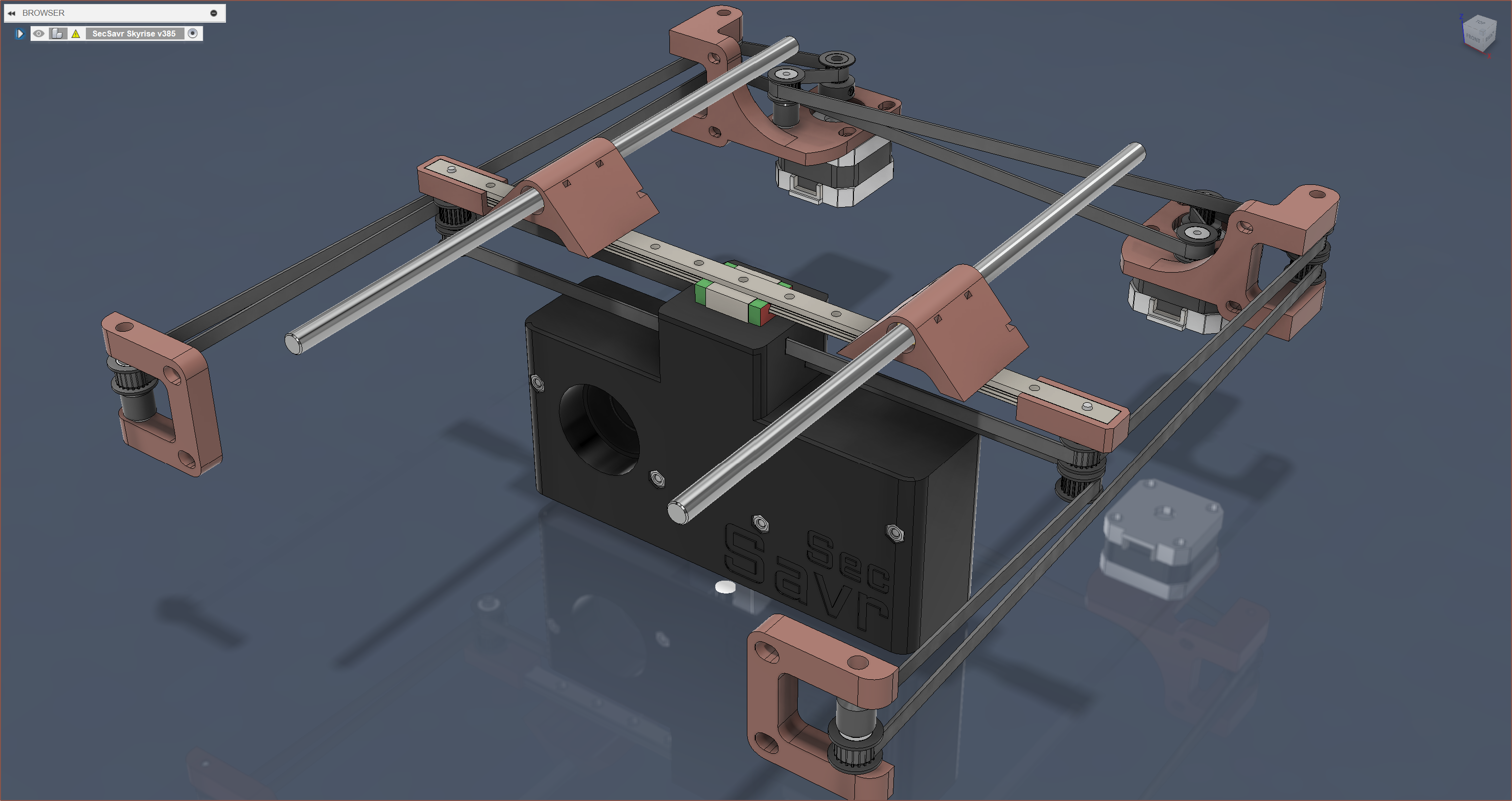
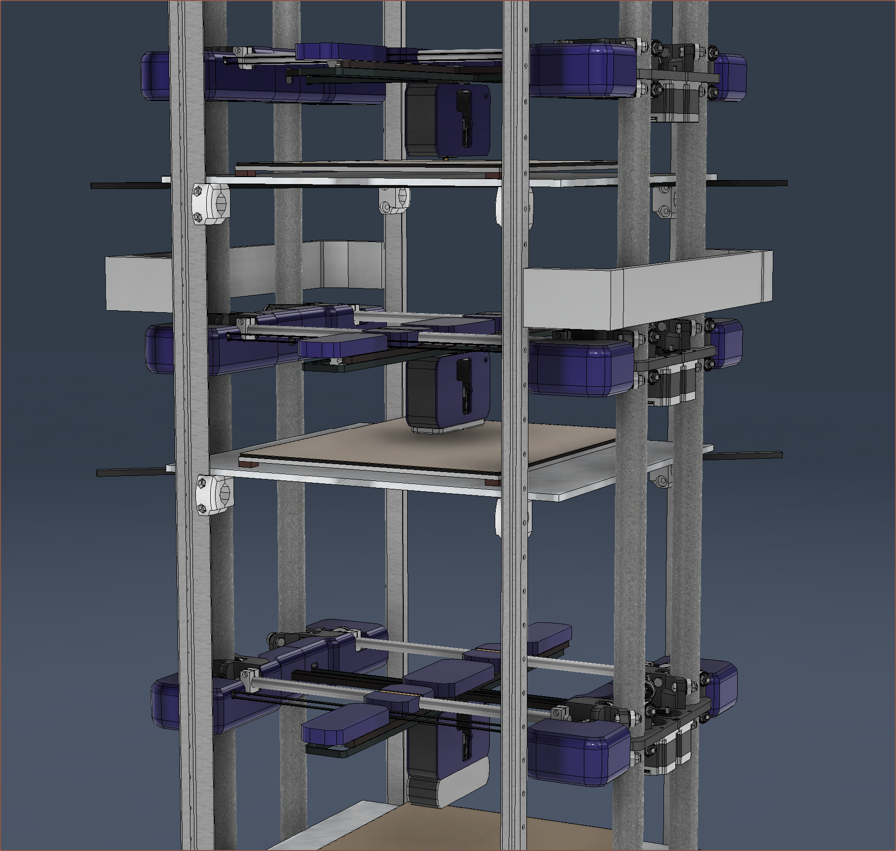
First it was taking the 8 inputs from the #SecSavr Select [gd0091]. Now this project is taking the slim and long designs seen in the #SecSavr Skyrise [gd0092] and the SecSavr Space (the printer that would eventually morph into the #SecSavr Sublime [gd0036]):
Additionally, I've modelled the Coupler Plate as well as the Hotend Holder:
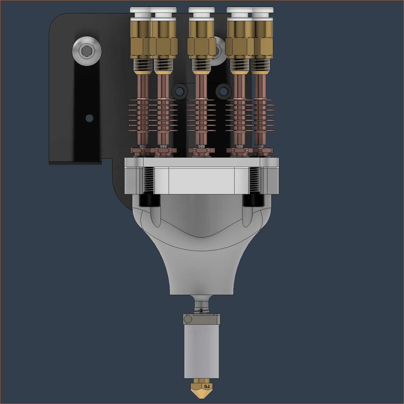
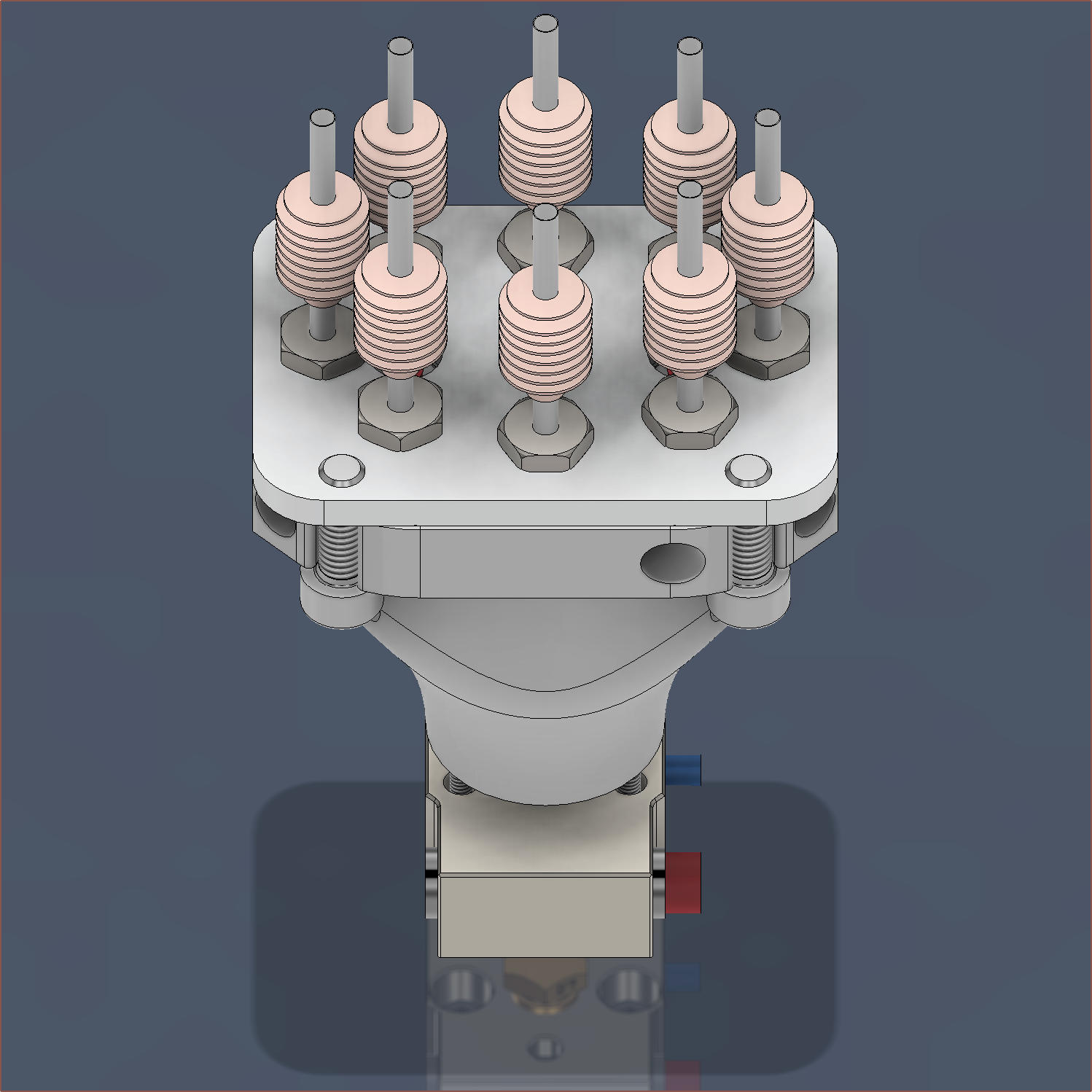
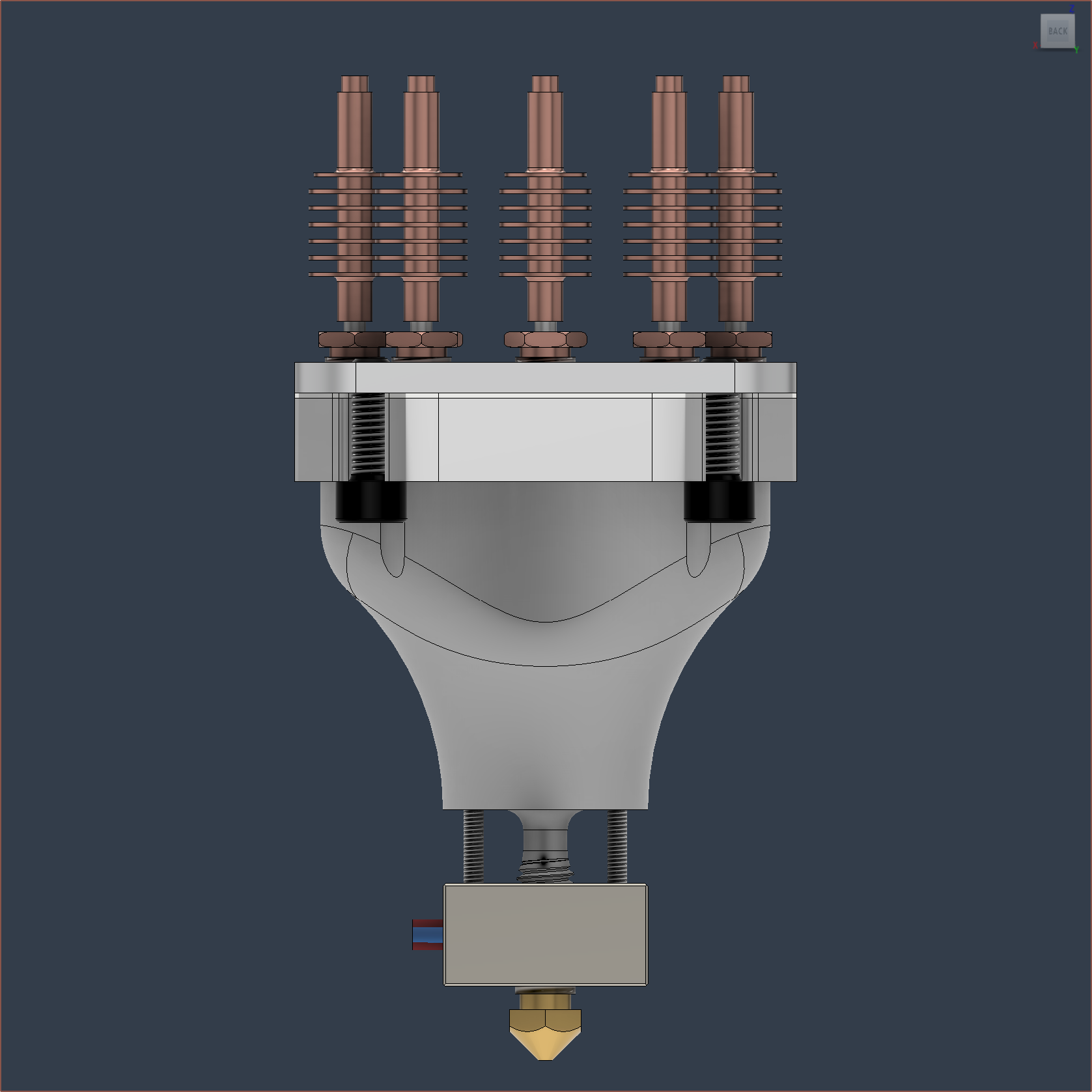
Overall, I find it nice to think about how technology has advanced to be able to (idealistically) miniaturise Deckingman's 6-input hotend to a size that can be easily installed onto a CR-10, despite adding 2 more inputs:
Source: Deckingman I still have to model the part cooling though. Not sure if I should just do a basic blower or freshen up on the latest research in cooling ducts.
-
[B][C][M] Preparing shopping cart and Marlin
02/10/2024 at 16:45 • 0 commentsParts to upgrade from 4-in to 8-in
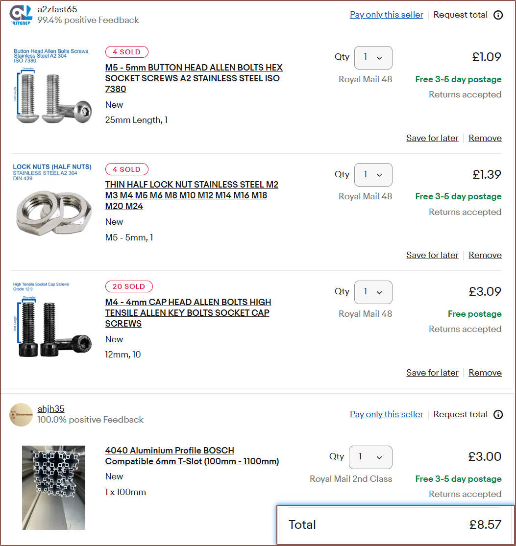
Ebay
I just need 12mm M4's for the clamp plate and I'll be replacing the 2040 100mm extrusion with 4040mm as I plan to use Nema17s that are half the thickness (and hopefully weight) as the 4 steppers I have now and use mirrored BMGs. I also need clearance from that X-gantry bolt that sticks out. More about that below.
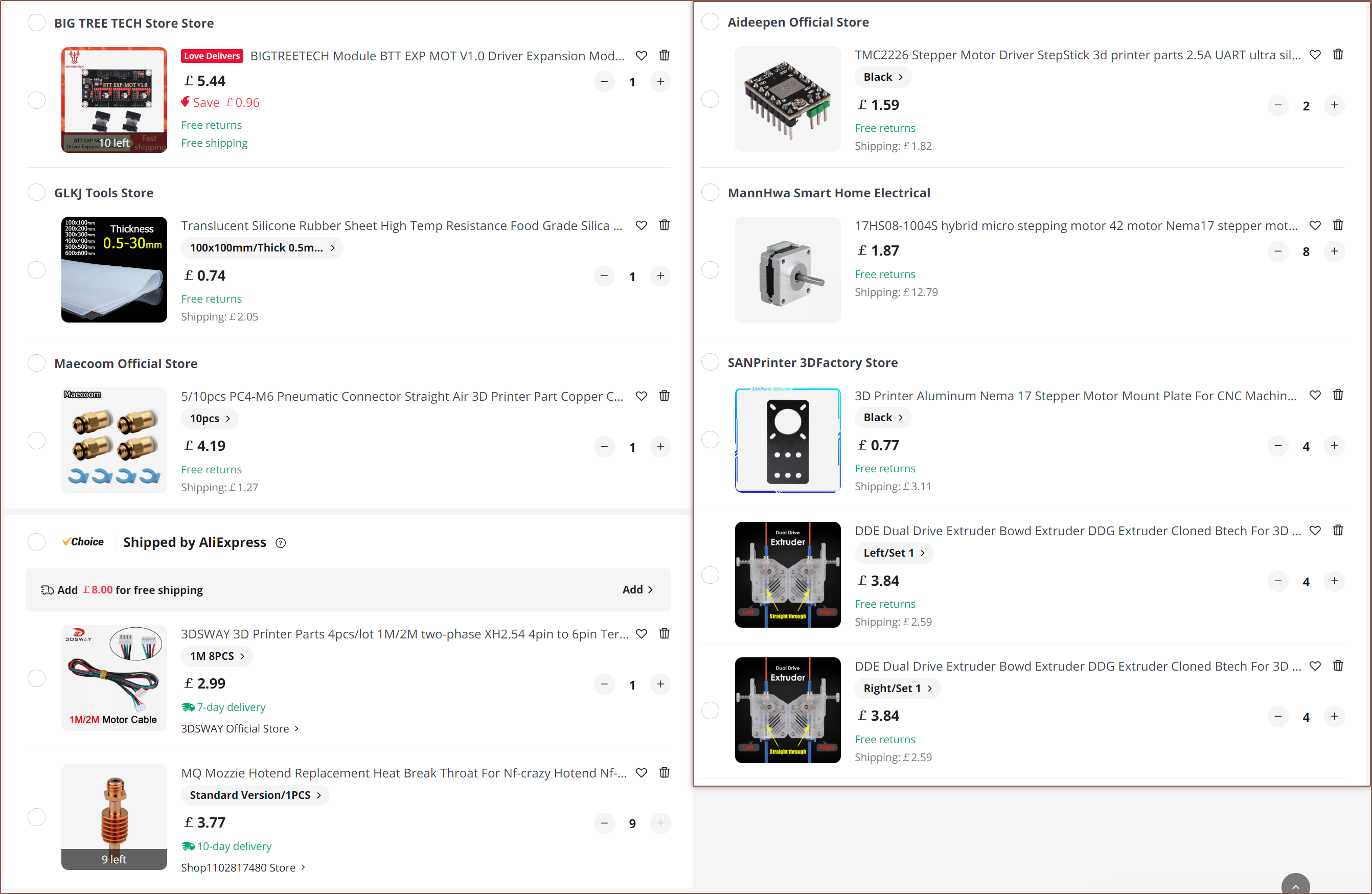
AliExpress
Some quick things first. I've only got 6x2209s so I need to get another 2 stepper drivers for the extruders (and the 2226s are the same thing in a different, larger package that theoretically dissipates heat better). I couldn't see any cable at all in any of the motor images so I just added 8pcs of cables in the basket (which are also the right connector, instead of Dupont that 3 of the 4 motors use).
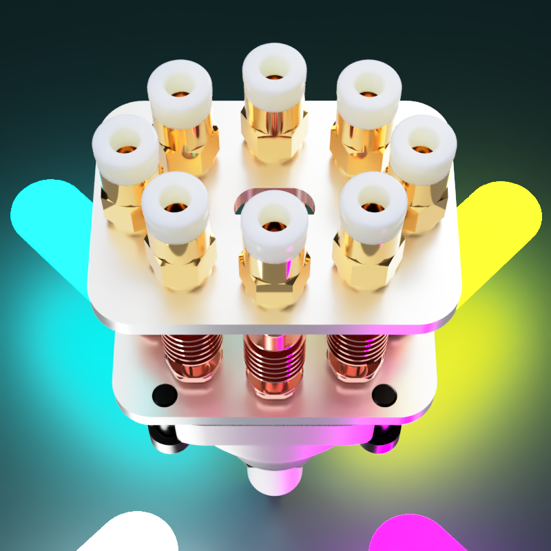
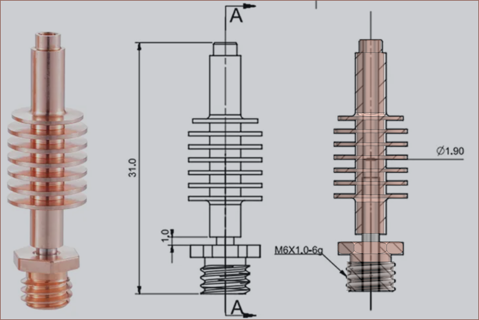
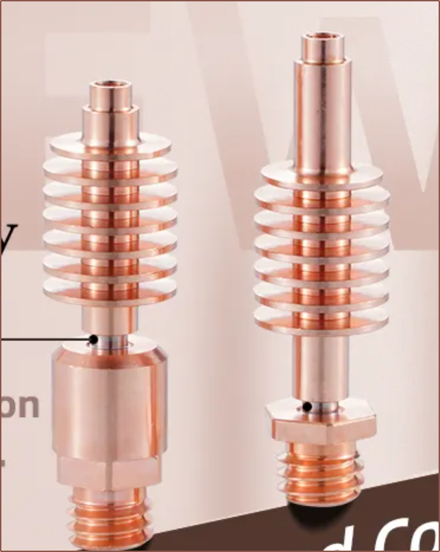
Let me start with the PTFE tube situation. I can't use compression fittings unless I want to also increase the distance between heatsinks, thus both a larger hotend and higher costs. The KJH-04-M6 bowden couplers were the only ones that also have the same 8mm across-flats hex. They conveniently also have a 2.8mm exit hole which should pair perfectly with the estimated 2.65mm tops of the heatsinks. I found a good image to use as a reference for CAD and modelled it:
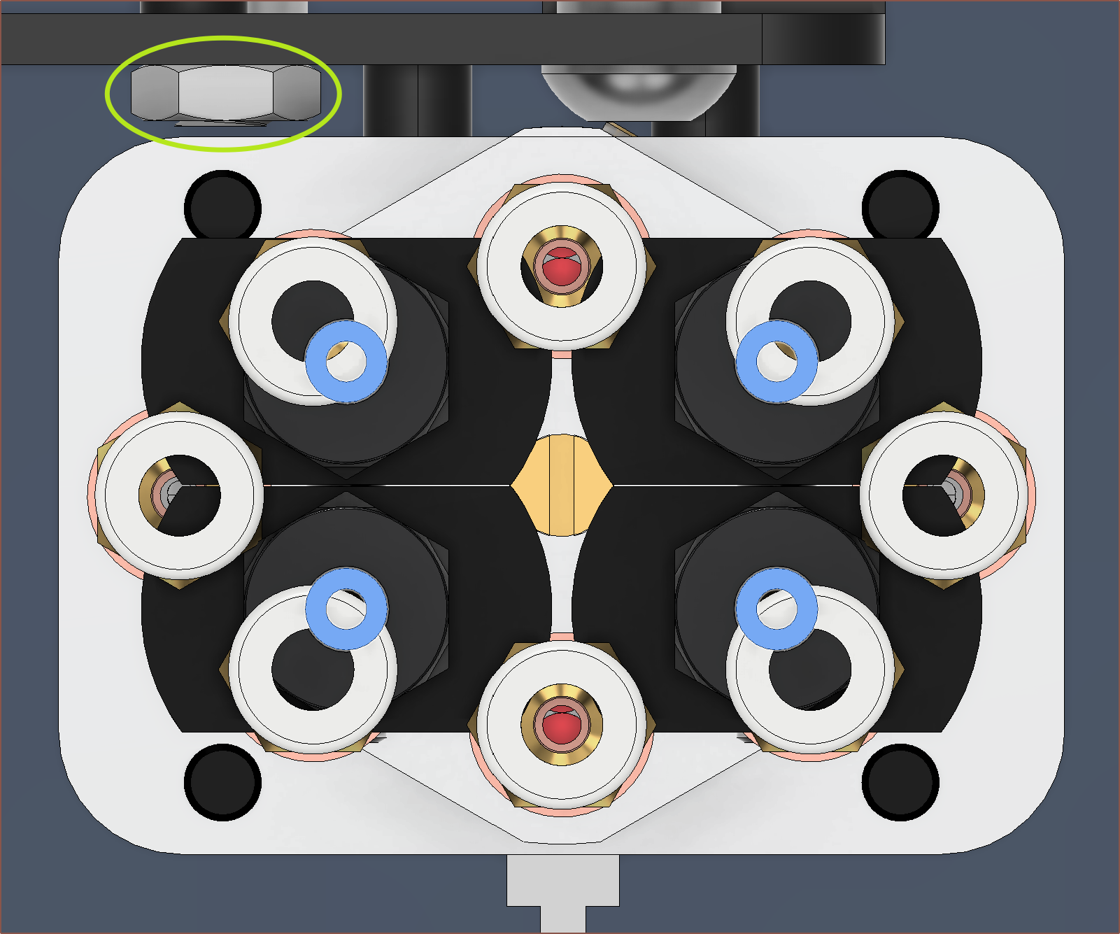
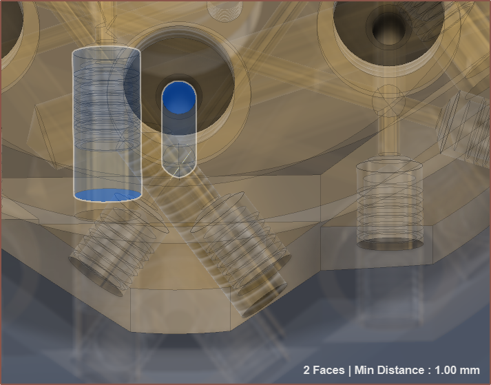
I laughed when I found out that the bowden couplers would be about the same height as the gantry plate, just like how it is for the Machined 4-in-1-out hotend. Also, if you were wondering, the entire height from the top to the nozzle is 125mm If you want to see the difference, look at the below image with the 4-in inputs highlighted in blue. It's almost as if the extra 4 inputs were just squished inbetween the original 4. Also notice the bolt circled in line green. With a M5x25 bolt and a DIN439 thin bolt, I believe I can get the space I need to mount the hotend with minimal loss of Y.
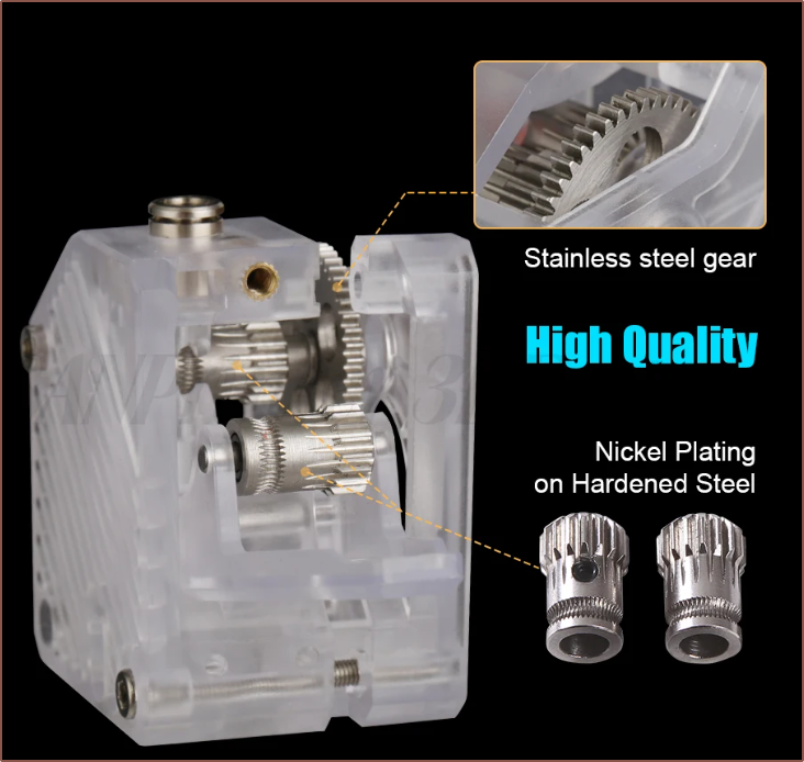
I could also flip the bolt the other way so that the bottom wheel has the bolt cap on the same side as the top 2 wheels, For the extruder, I've gone with 4pcs of both left and right of the "DDE" extruder because they're half the price I was expecting to pay for more BMGs, they look nice (cool diagonal lines and no "extruder" sticker), they're translucent (so I should potentially be able to see the filament pass through when loading/unloading), they come in both left and right variants (unlike some similarly priced BMGs) and it's from a reputable AliExpress store that I believe make high quality stuff.
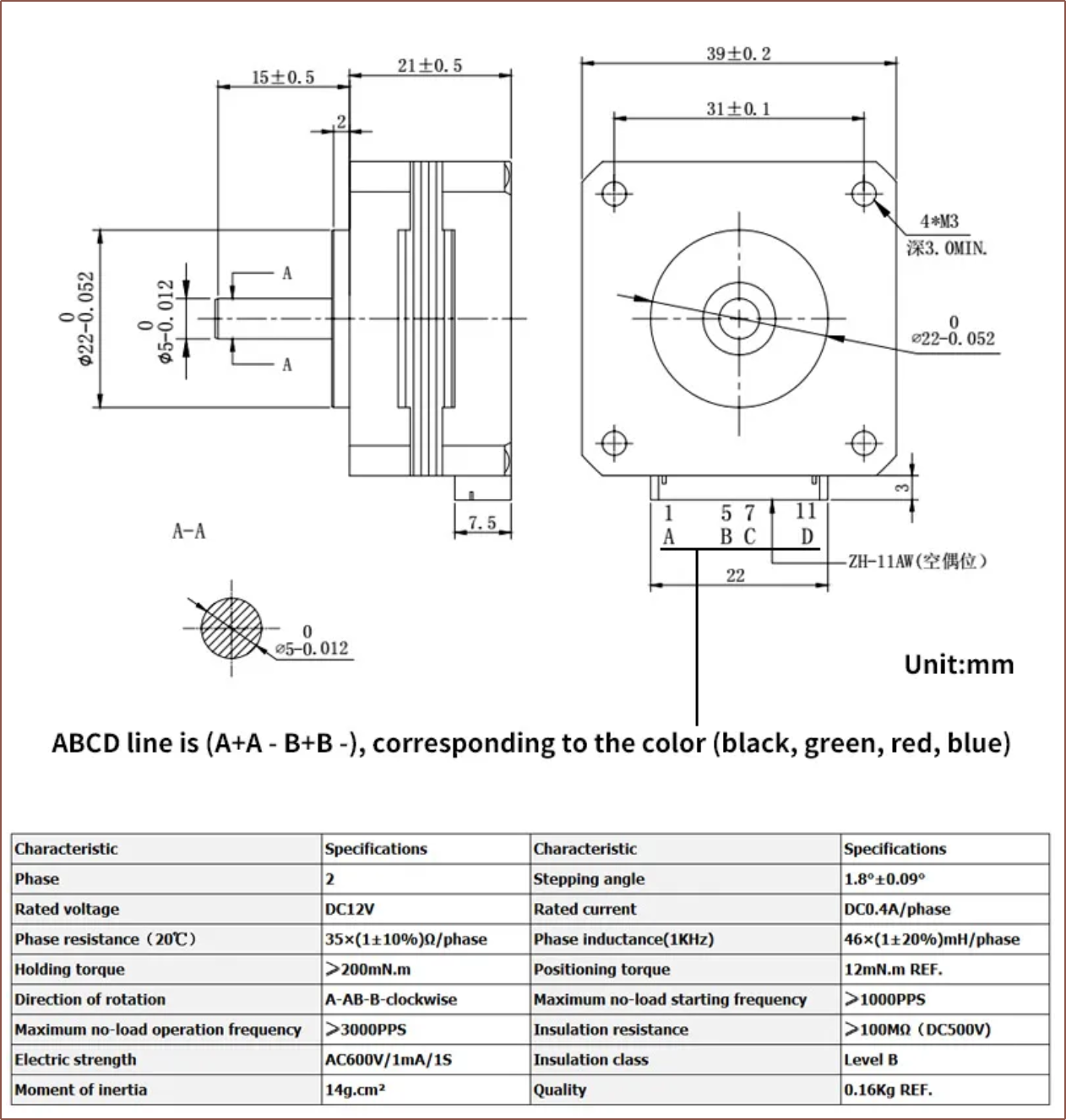
It also looks high quality with its top bowden coupler and large steel gear. The extruders are to be powered by 0.4A Nema17 motors at the lowest price I've ever seen for Nema 17s. Since the BMGs 3x the torque and the amount of force required to extrude at higher speeds seems to increase exponentially anyway (meaning that a 2X stronger motor may only increase throughput by 1.4X, for example), I think they'd be ideal for moving filament. I'm planning to run them at 300mA, which is half the current I've run the current extruders. Other than the shaft being a plain O instead of a D, I think this solution is ideal as it means that I can place all 8 filaments on the same side of the printer.
I'm planning to use some washers on the 4040 extrusion so that the 2 motors, which will total a thickness of 42mm, will fit. Marlin
For some reason, Marlin supports 8 extruders. I've looked around and I don't think a single printer comes close to that number, so it's very convenient that the Marlin devs are looking ahead. For some reason though, M165 officially only supports 6 of the 8 extruders, even though mixing hotends support the full 8. It's a very easy patch though:
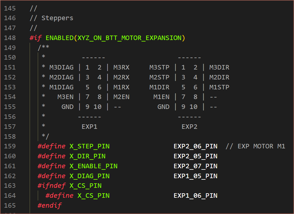
I looked to make sure that J and K were not used for other things in G1, like "E", "F" and "G" would be. This is because there is a "mixing in G1" feature. What was a bit more tedious to implement was the pin reconfiguration so that all the extruders were on the Octopus Pro and XYZ was on the EXP MOT. The trip-ups mainly stemmed from TMC related pin setup of DIAG or UART pins being in separate parts of the file and not with the stepper definitions, thus I had to move them.
Under all the stepper driver definitions, I've added a few lines in the config:
Obviously, I'll have to turn off all LCD features and rely on the touch screen interface.
Conclusion
It does seem that, if starting from a typical £399 FFF 3D printer in the CR-10/Ender 3 style, upgrading to this 8-in-1-out is going to be something in the ballpark of another £300. However, I think that the value is still there if there was a hypothetical listing of an 8-extruder printer priced at £699 if the hotend works as intended with features such as:
- allowing for a spectrum of colours without having to buy a spool each time
- the potential for increased mechanical properties such as increased inter-layer strength, potentially allowing ABS to be printed in the open without delamination.
-
[E1][M] Printed Coaxial Hotend with clamp plate
02/03/2024 at 16:03 • 0 comments[Feb 03]
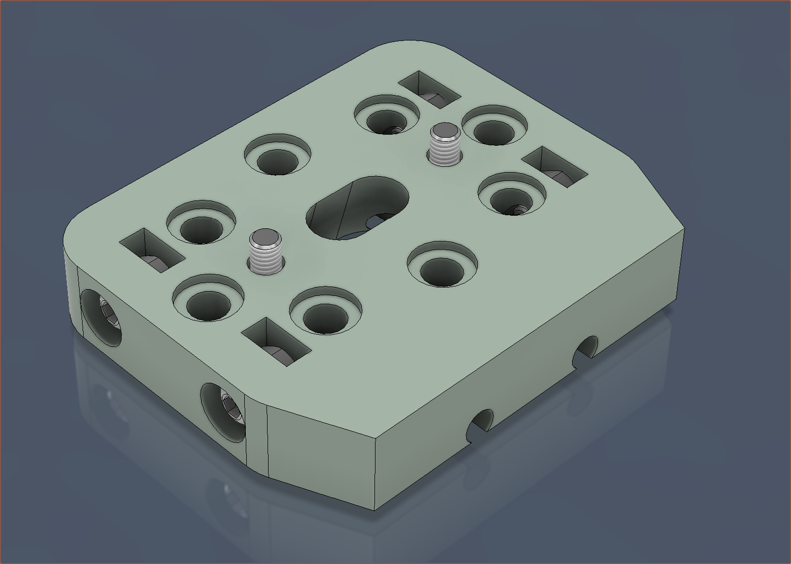
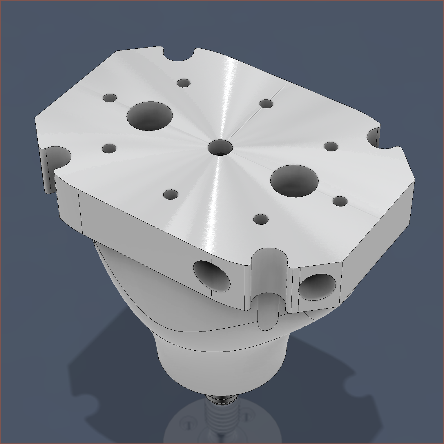
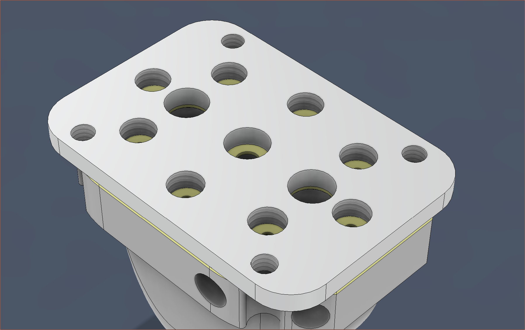
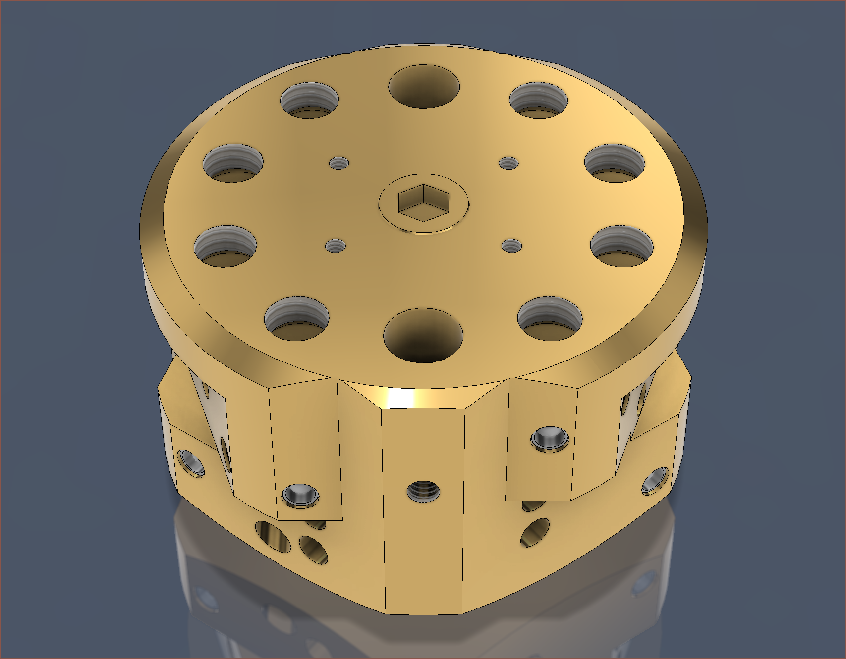
So I just wanted to see some stats on what a fully tweaked design that I suggested in the previous log would look like (and cost) so I spent the past 2 hours doing just that. The idea is that the top face (shown above) and the bottom face of the M6 is lathed down so that it's much smoother than the raw print, and then a plate is screwed into the top which itself contains threaded holes. Unlike what has been experienced so far, these threads will be able to completely go through the material without imperfections.
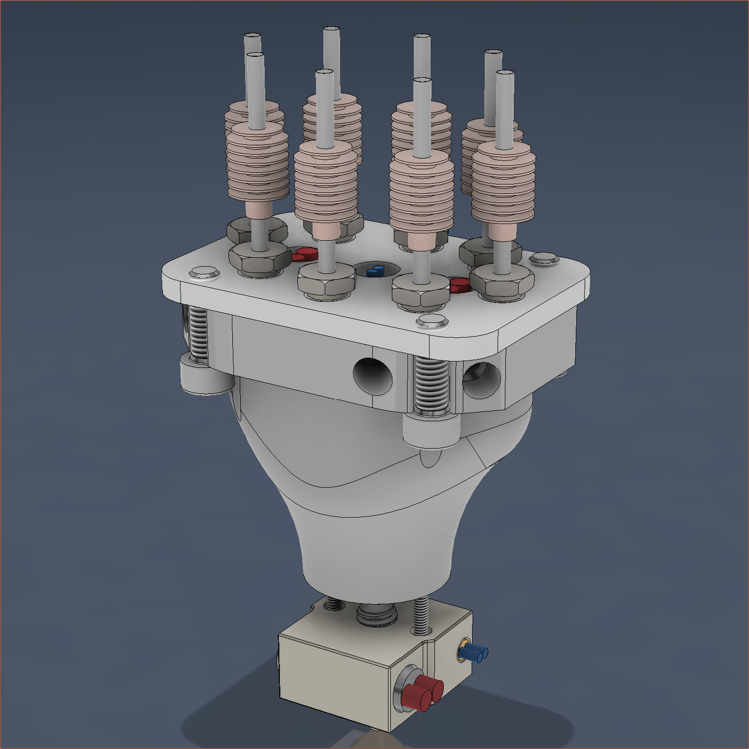
When everything is put together, it looks like this:
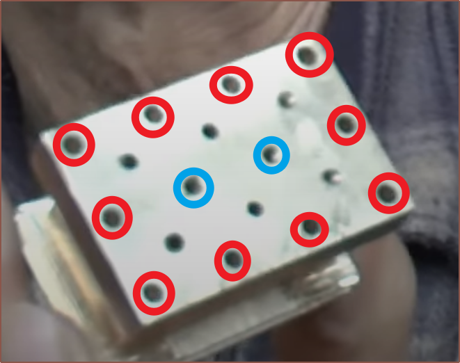
My only worry is that deckingman used much more screws to clamp it down in his design, and the clamping plate is probably at least twice as thick too.
The red marked ones go through (like in my design) and the blue marked ones are tapped into the block.
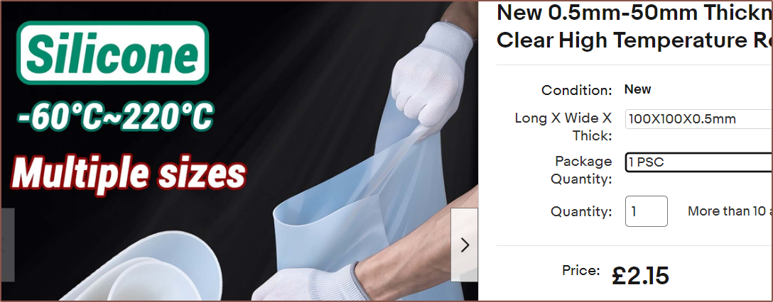
I'm wondering if a cut sheet of PTFE / silicone / kapton could be used as a gasket seal, potentially even eliminating the need for the polishing of the top face:
Wait a second...
(Mentally) Computing a pressurised system.
Simulation...
successful.
Isn't this precisely what gaskets are used for in other industries? I guess a gasket would be hard/tedious to implement in a normal 1-in-1-out hotend, so that's why it's not used and a metal-on-metal contact is relied upon. It seems that a 0.5mm or 0.8mm gasket would be fine:
I presume that I can figure out some kind of mounting strategy by adding threads in the clamp plate for some titanium bolts.
If there are no surprises, I expect the print cost itself to be around about $60 and the full price to be in the $80 - $100 (£64 - £80) range.
Everything visible here should be ~165g. This should solve all the expected issues other than the surface roughness of the print itself. I don't know if 1.25mm is going to be wide enough for the minor channels nor if 0.8mm between the knife-edge and inner tube (that the thermistor goes into) will be enough space. There's also the question on if I can actually just grub-block unused inputs or if that runs the risk that those paths could get permanently blocked with charred filament.
[Feb 04]
I've spaced the gap between the knife edge and the internal cylinder from 0.8mm to 1.0mm just to give the least chance of powder imperfections affecting the output. I've also corrected the heatbreak model and given it a much more copper-looking tint:
As for the mounting situation, I'm planning to mount it facing backwards (as it's unlikely that I'd need to touch the cartridge grub screws) and use grub screws that clamp onto the 3.5mm tops of the diagonal 4 heatsinks. The 2.65mm topmost part should be able to sit inside the compression fitting's 3.2mm bottom hole and there would be little reason why said fitting would need to be expanded so that the bowden could come though.
I also did some research on the seal and the recommendation is the thinner the better.
The entire printed part PCBWay price is $78.17 (£61.95) with standard global shipping.
This design should also mean that only the easier-to-make clamp plate would have to be remade if the threads are misaligned or need a design change.
-
[X][P][T] CR600S setup and first test prints
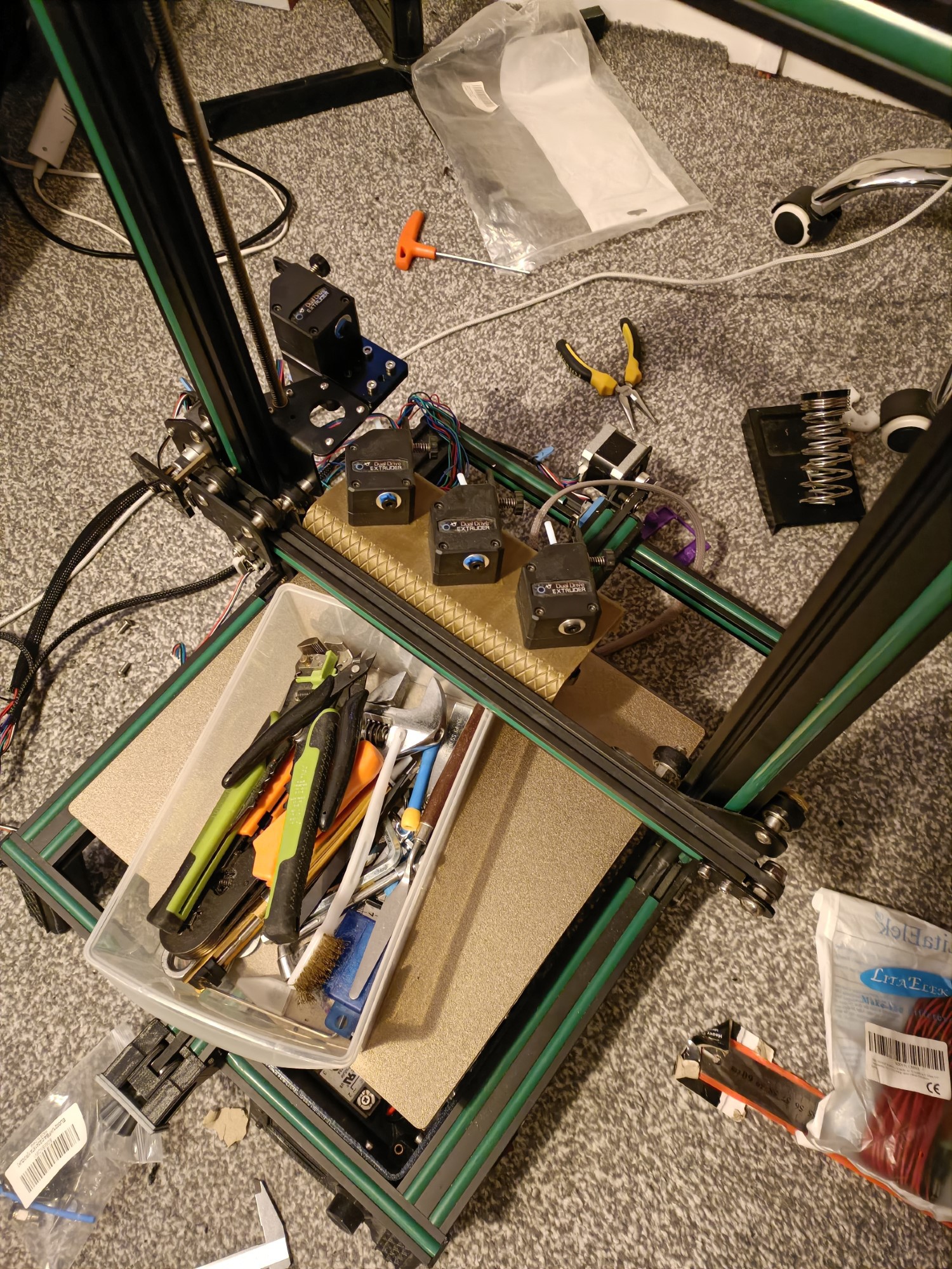
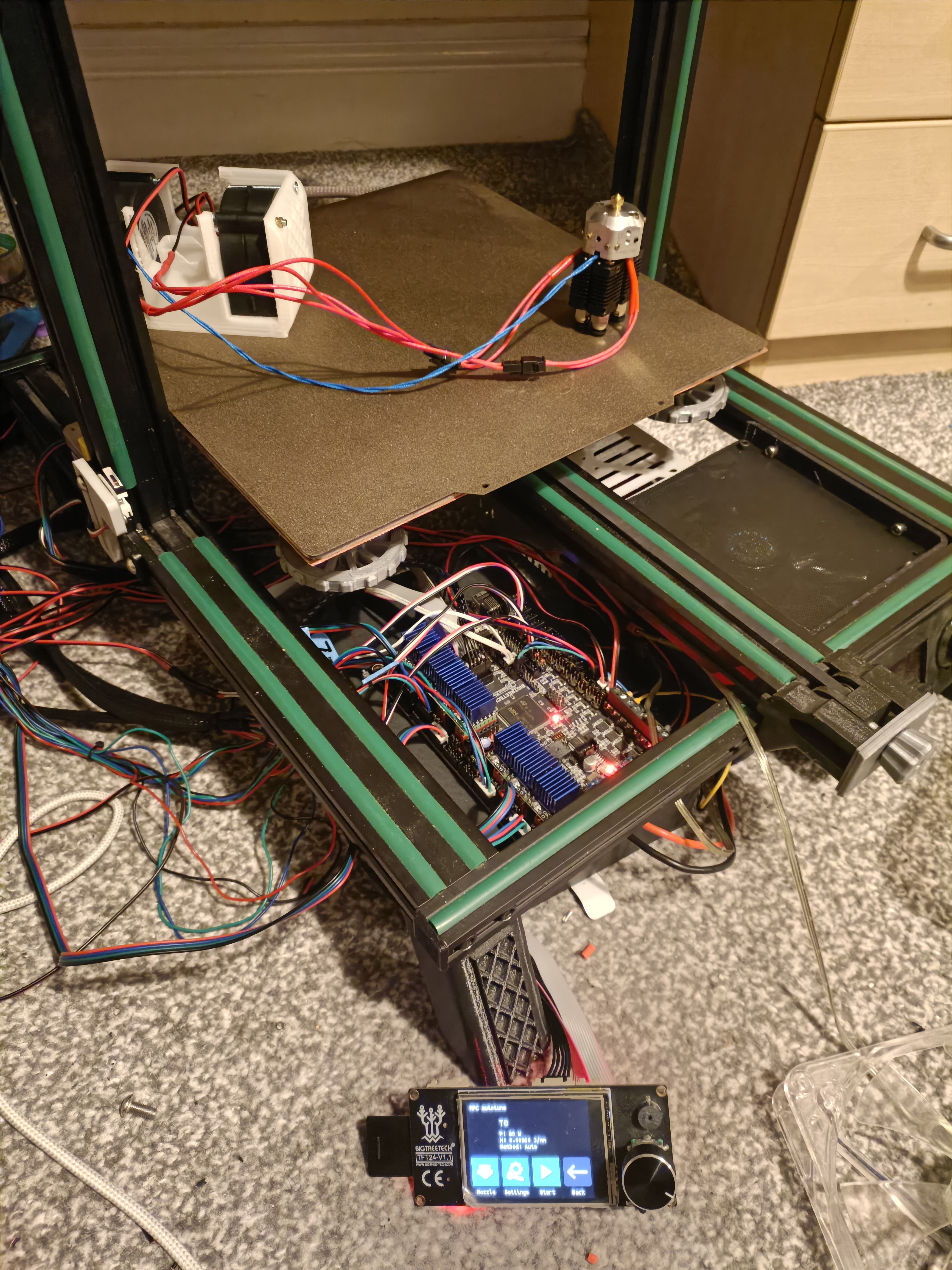
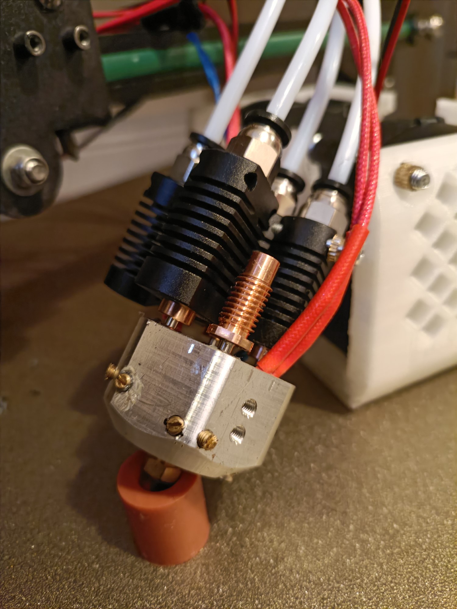
02/03/2024 at 08:13 • 1 commentIt took much longer than I expected, but I've finally turned the pile of parts into a CR600S to conduct printing tests with the 4-in-1-out Machined Coaxial Hotend. Unfortunately, it lost against the leaks and the results I was able to get out of the two test prints were inconclusive other than knowing that I can print 100% in extruder E0 and E1.
Putting the printer together
I started putting the CR600S together on the 23rd Jan, found out what parts needed to be ordered on the 24th and got them in on the 25th and 26th.
Extruder mounting
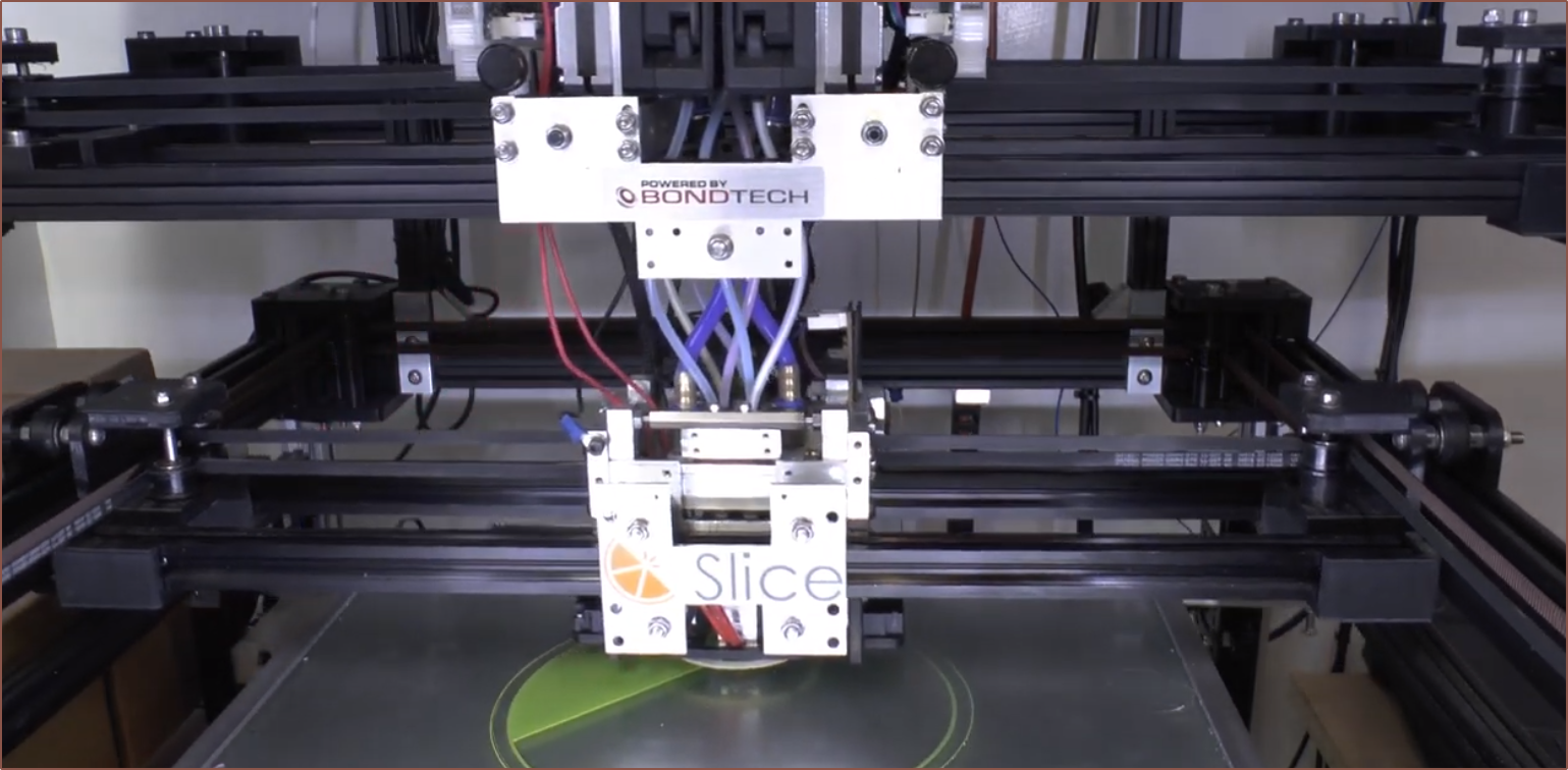
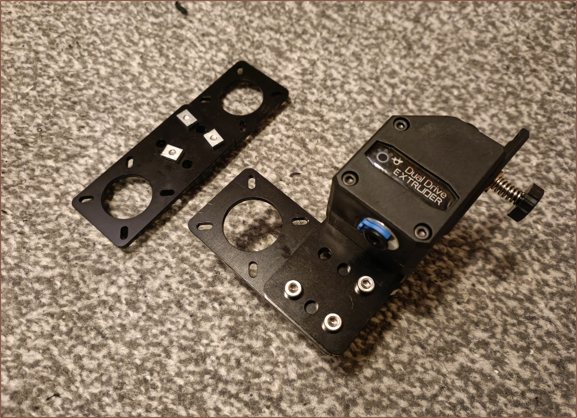
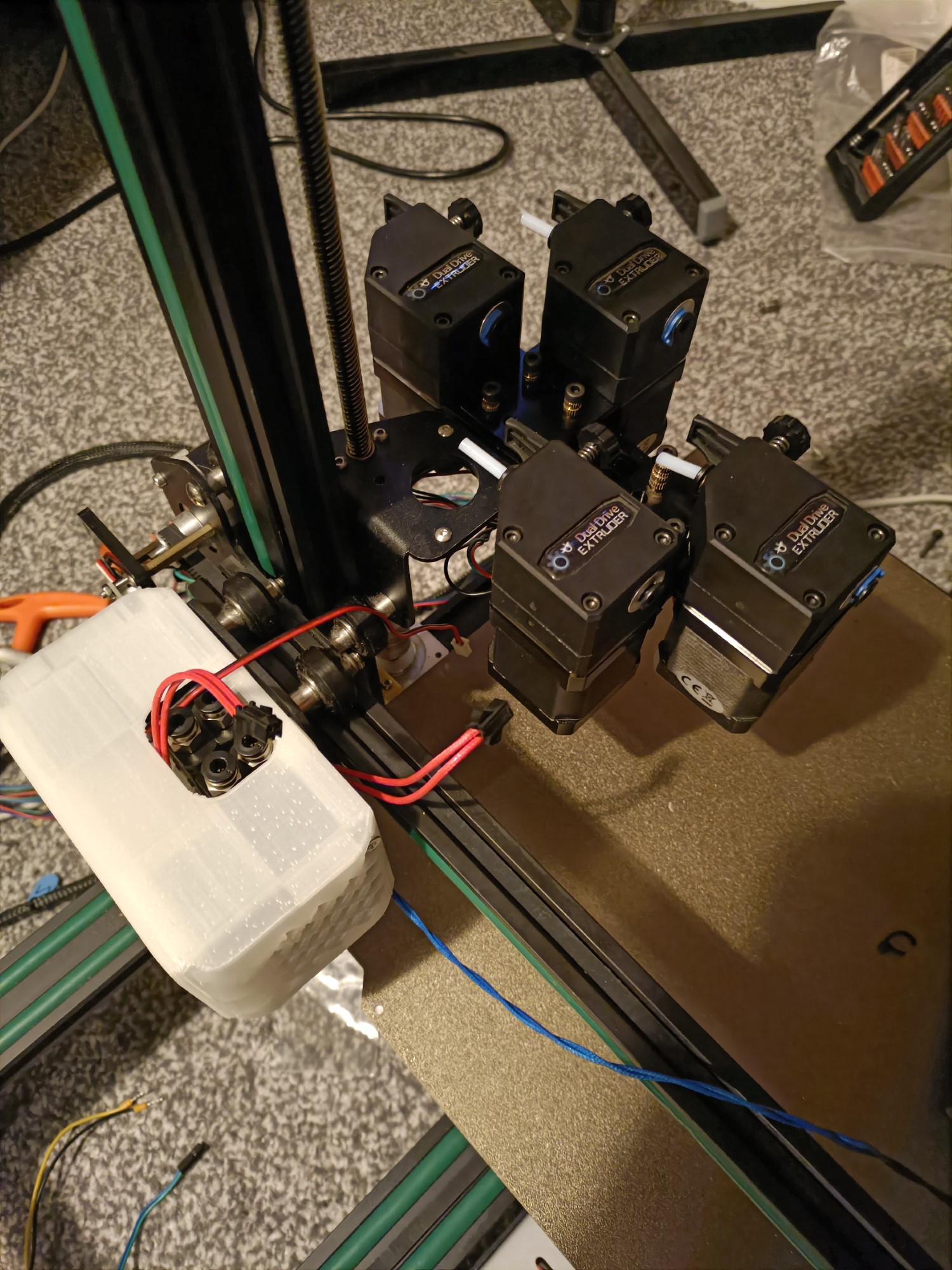
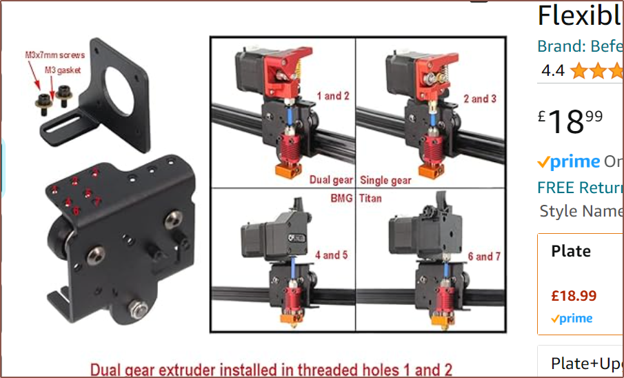
I had some Nema17 mounts from when I was testing for the #SecSavr Sublime [gd0036] and I figured out how to be able to mount them to the CR600Ss extruder mount plate:
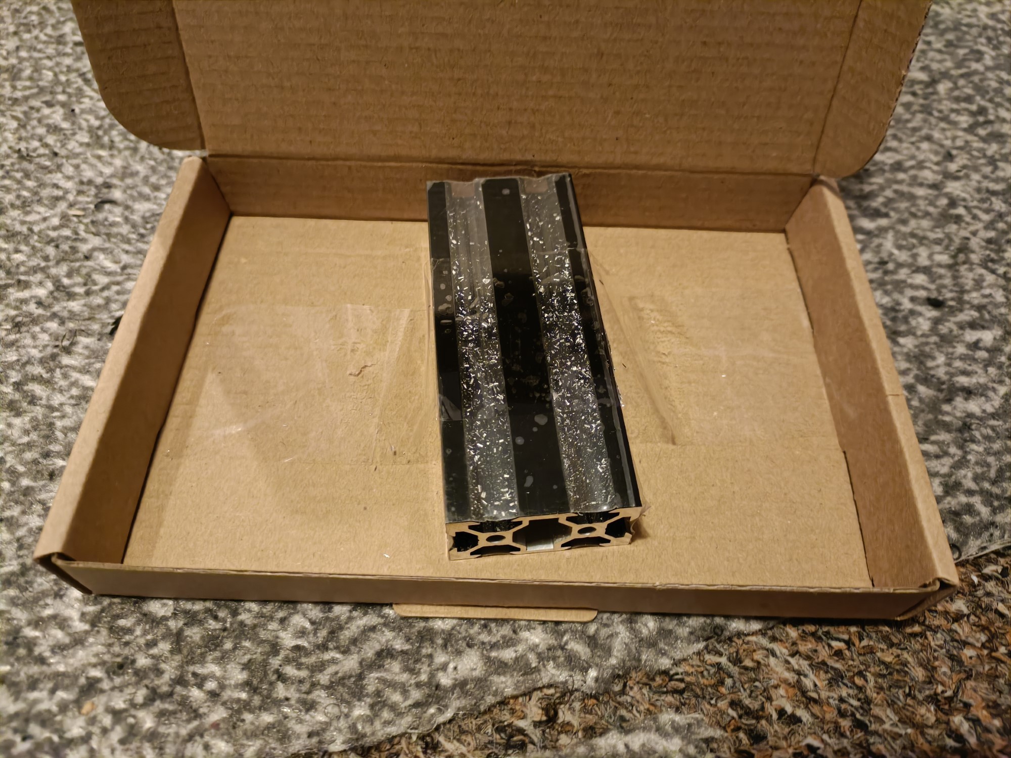
I figured out that it would be possible to get a 10cm length of 2040 extrusion to actually use all 5 mounts I have to mount the 4 extruders.
E2 gave me the most issue because, as I was installing it, I noticed that the grub was loose. It also wasn't tightening correctly. I put in a grub from the bag of them, but then I noticed that some motors could be spun from the white gear things and others can't. For all but E2, the issue was that the gear was too high up. However, it took me trying the E2 extruder on E3 to realise that the (longer) grub screw is the reason E2 wasn't working. I had to transplant a screw from one of the BMG gears I got for the #SecSavr Select [gd0091].
Some other parts ordered
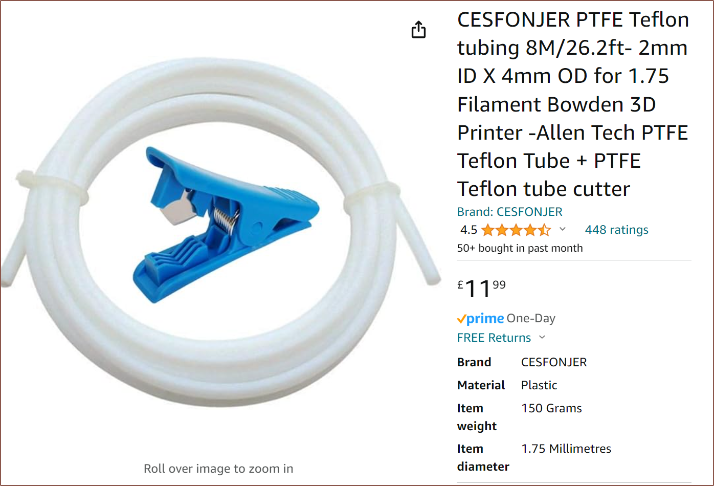
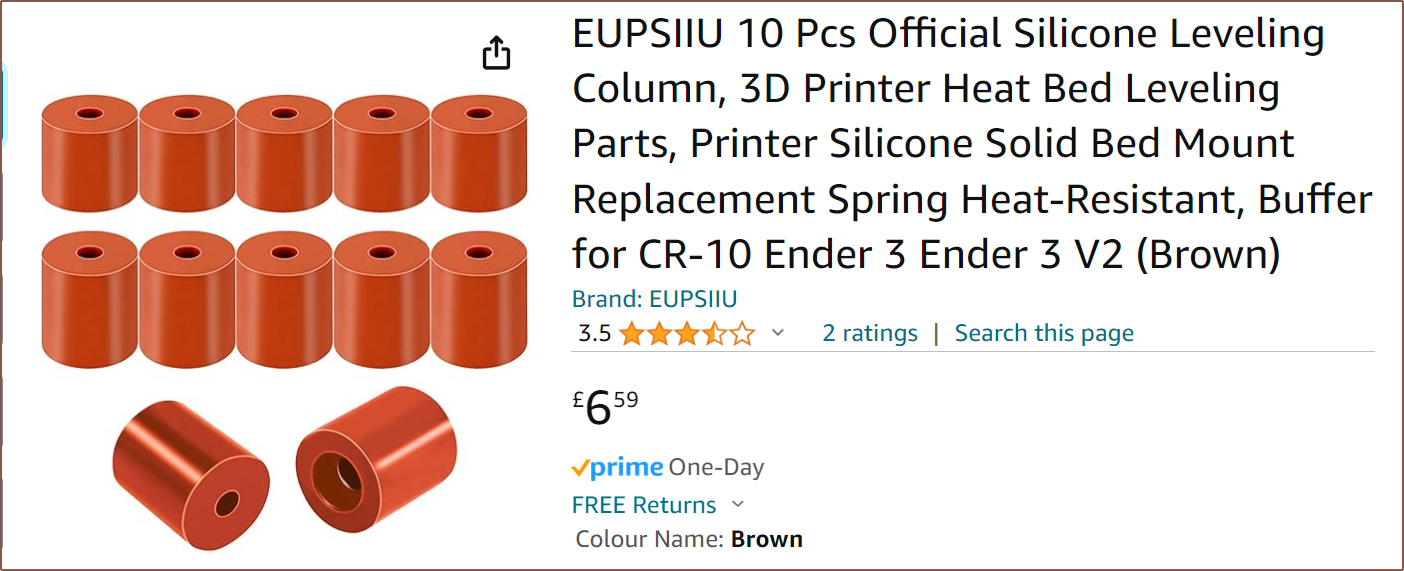
I decided to get this 8 meter bundle for £12 instead of a 2m for £7 because all this is experimental and there was a possibility I'd need more than 2m. I went into this thinking that I could get 5m for £5 or something. The included cutter makes things so much easier than what I did in the past, which was a scalpel against a hard surface. I got this instead of the cheaper £4.59 option because I specifically wanted at 5 of the same height so that I could put one under the center of the bed, which is slightly lower in elevation than the corners. It wasn't until I was wiring things on the 29th that I realised that I hadn't actually seen my box of ferrules in years, so I got 600pcs of those.
Parts redesigned in CAD
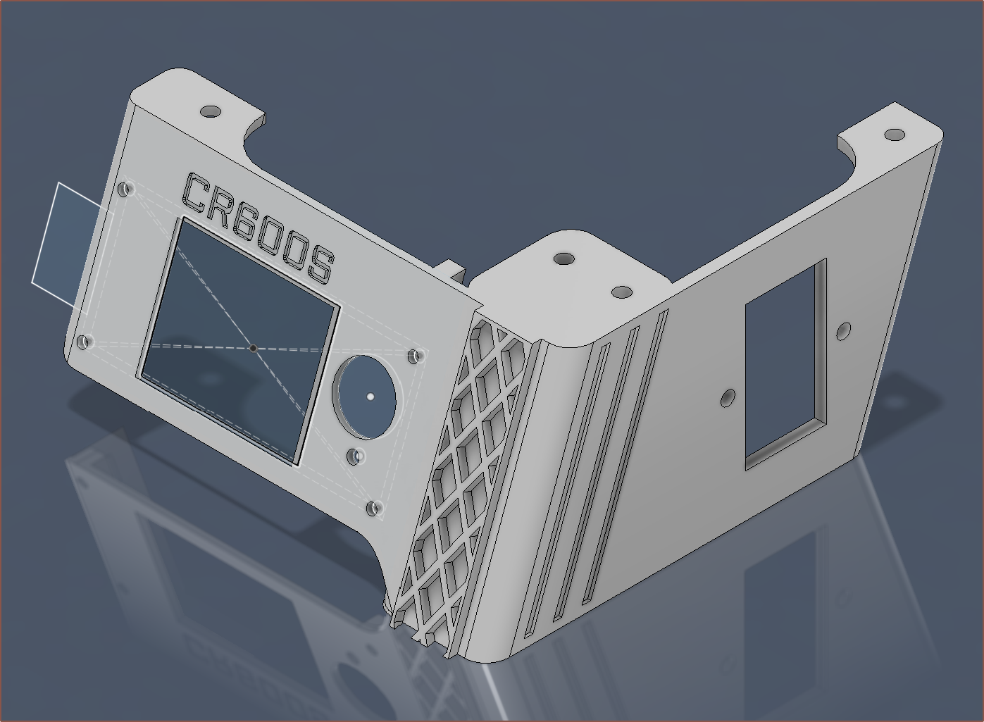
The only thing I modified so far was the screen foot:
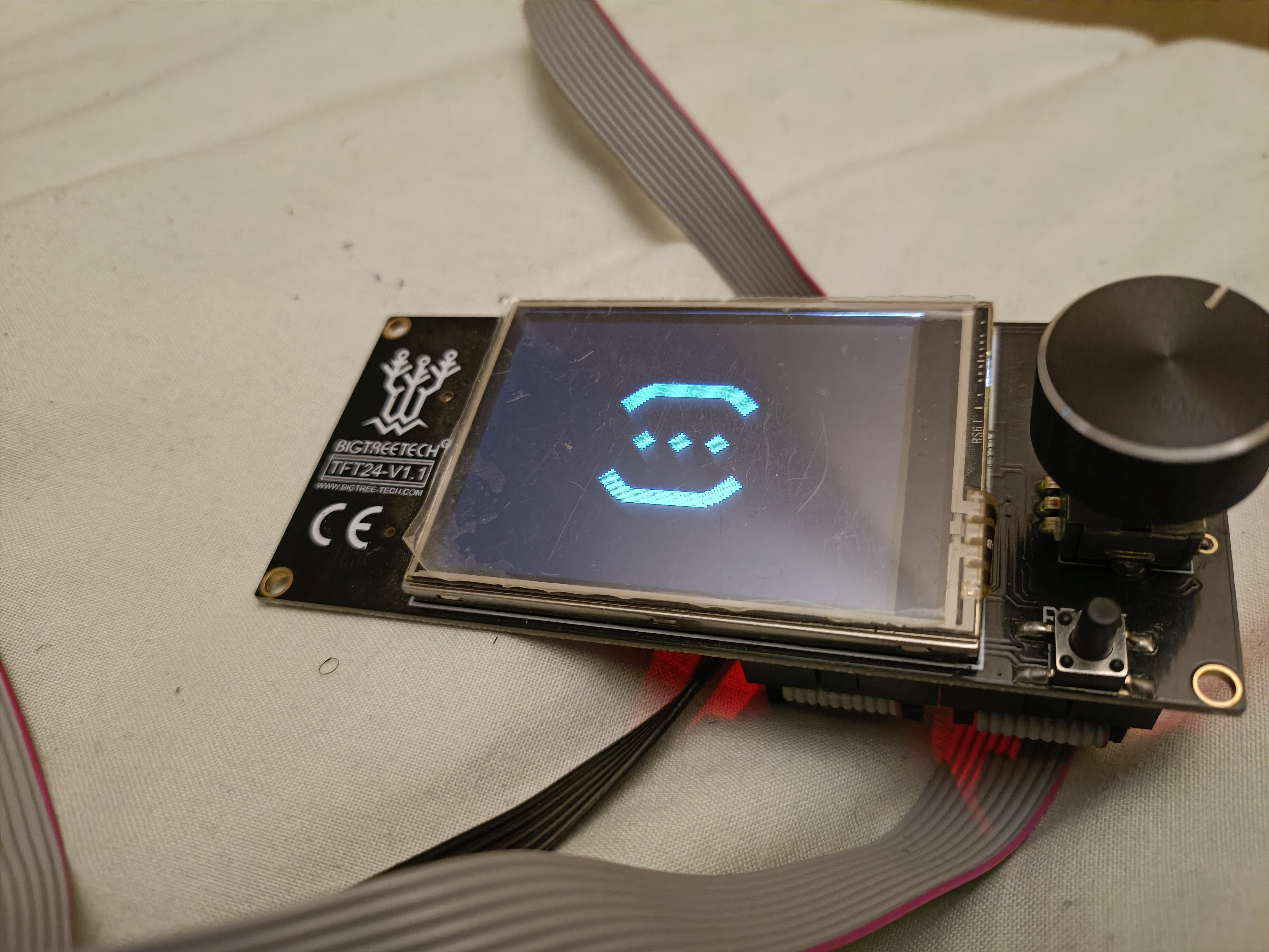
The dimensions of the BTT TFT24 were very similar to the FysetC RGB 12864 installed currently. The plan was to use this as a test print.
I added a cutout so that the mains wires didn't have to be disconnected when swapping this part out if needed in the future.
More mechanical ideas
Possibility of a micro-bowden (direct drive) fed input?
This is what gave me the idea:
And this is what I plan to use:
BotObjects heatsinks?
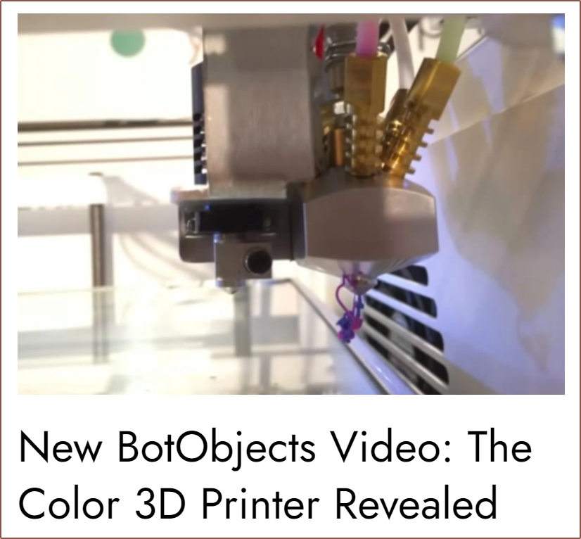
Whilst on my Fabbaloo travels, I came across this:
As you'd see later in this log, I think something like those brass inserts is something that is really needed if either the Machined, Printed or Unibody Coaxial Hotend is going to work long-term.
Firmware changes
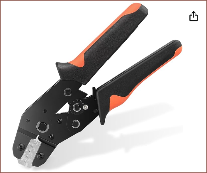
Swapped the bed and E3 pins so that I didn't have to connect a jumper set of cables just so that I could power the SSR (which certainly doesn't need bed-heater levels of current to run). I'm not sure why, but there is a specific build environment specifically to use the USB A port on the Octopus Pro. This is used since the leg would block the one on the TFT24. JST XH crimping using the SN-2549
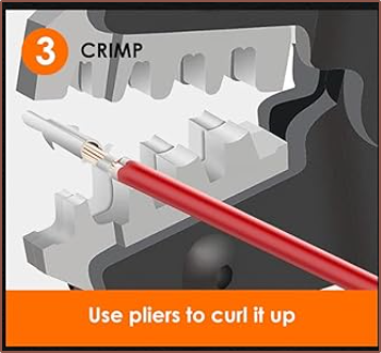
As I lost one of the jaws from when I was trying to make my own ball-chain splicer for #Tetrinsic [gd0041], I got a new one:Unlike the one it replaces, this one has a narrower and smaller jaw at the end that I tried (only after multiple unsuccessful attempts with the 0.25 option) that didn't malform the crimp.My JST crimps came all separate. I've seen some YT videos where they first have to be cut off a line of them. The best strategy I've found seems to be the following:- Change to the lowest pressure setting
- Remove a bolts
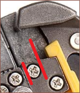
worth of insulation on the wire
- (there's a bolt head that spans from the cutting edge of the stripper, so that's why I say that)
- If in doubt, strip shorter. There really only needs to be 3ish millimetres of exposed wire.
- Use a 2 pin JST-XH female to
hold the crimp mounted
vertically.
- If horizontally, the unused pin will hit the crimping jaws
- This also protects the small tab on the underside from getting crushed.
- Place crimp into 0.08 option
- Crimp down till the jaw holds the male crimp
- Place wire in and validate that the insulation barely passes the large tabs (the ones that are supposed to crimp onto the insulation)
- Crimp fully and use the 2pin JST to pull it out.
Trying PTFE tape
I first did an MPC autotune which was very straightforward, then I kept the hotend at 140C so that I could unscrew one of the heatbreaks.After that, I tried to put PTFE tape on but ultimately failed.- Tried folding a strip in half and wrapping it around
- Too thick
- Tried cutting a smaller length and then cutting it in half to get 2 narrow lengths of tape
- Then I used an M6 bolt to testfit and it seemed that most of the tape got pushed up
- Tried to install into the hotend but I couldn't get it to go all the way down
- Spent 5 minutes taking it all off and just seeing how far I get with all 4 breaks tightened at 150C.
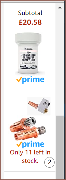
I then had an idea of using the hex heatsinks along with thermal compound as a possible future idea:Anyway, I cut 2 lengths of about 36 and 46cm (35 + distance between edge of plastic and cutter blade) and everything was ready for the test print.X axis endstop
I had to reorient the x axis endstop because the cover got in the way:Slicing
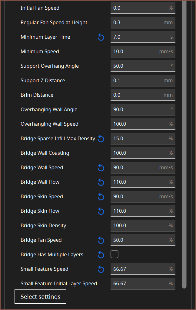
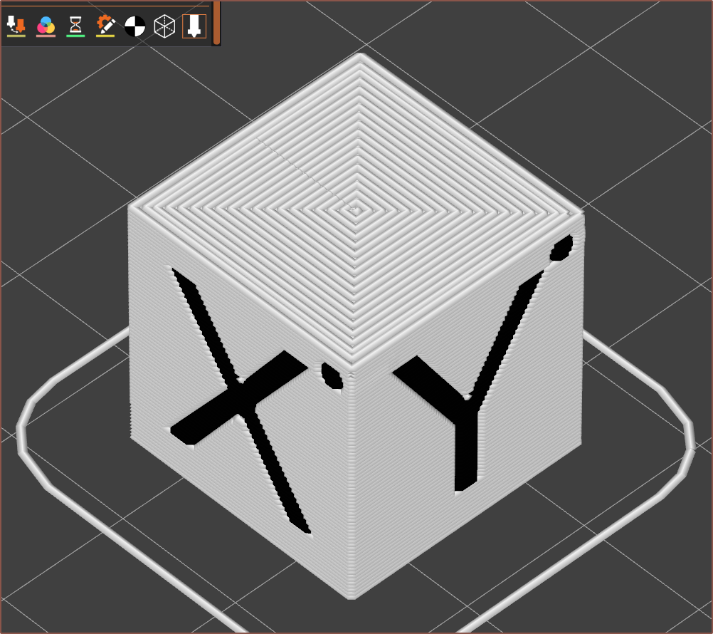
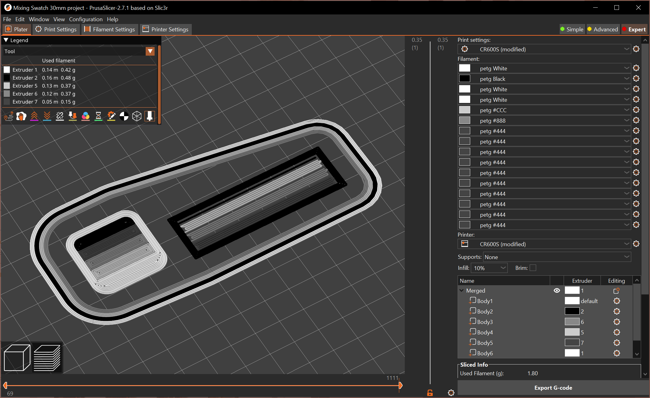
Well, looking for a slicer. Cura still only supports 8 extruders and the UI gets laggy. I looked into Orca Slicer but it seemed to only support things like AMSs and MMUs and not multiple extruders.In PrusaSlicer, I was easily able to add 32 extruders with no issue, but I dropped it to 16 as that was the amount of virtual tools set in Marlin. Also unlike Cura (even with the filament plugin), materials had things like custom GCODE and dependencies, so in theory I could add M165 commands for each mix and say that it should only be visible if specific materials are loaded into Extruder 1 - 4.Also unlike Cura, PrusaSlicer supports volumetric flow limits which means that I probably won't need access to almost every setting through the material like I do in Cura.Actually, I just looked through what I'm actually changing now. All the speed settings would be solved by the "Max volumetric speed" setting, I've never actually used ironing ever since I could get Cura (and now PrusaSlicer) to print concentric topmost/bottommost surfaces, typical things like extrusion multiplier and retraction is already in the PrusaSlicer filament setting pane, linear advance could be set in the start GCODE and I've actually never changed the bridge settings between materials (other than speeds).I threw together a profile that seemed to look OK (see above) and then modelled up a test mix swatch. I'm going straight into this because I don't know how long this heatblock is going to last so I should "move fast and break things" as Elon would say.First print attempt
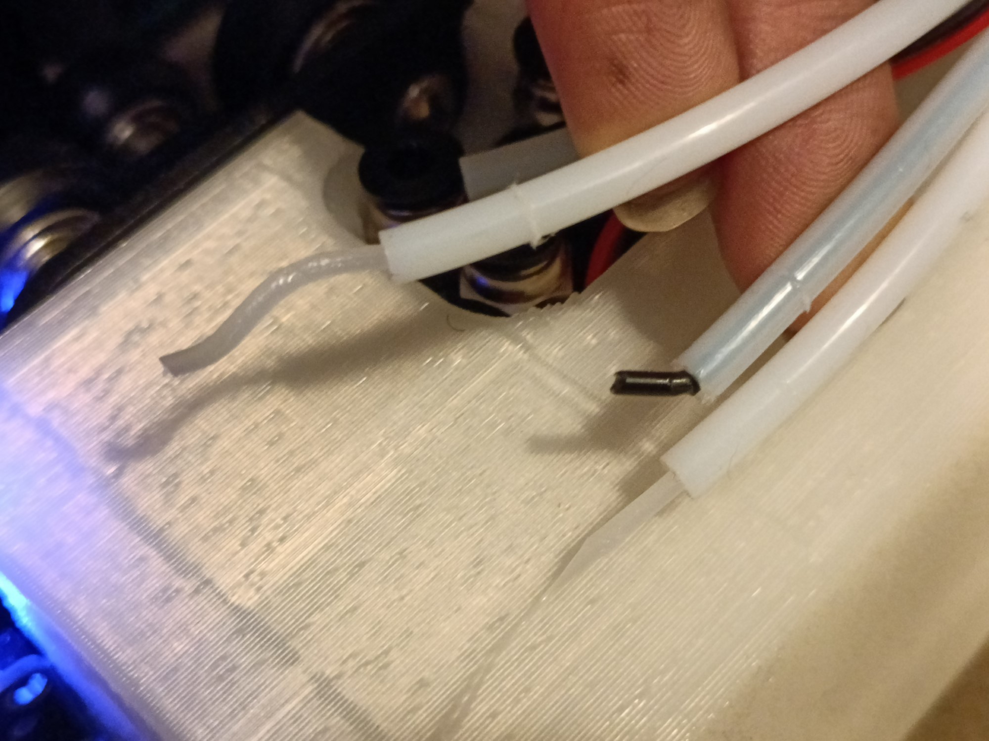
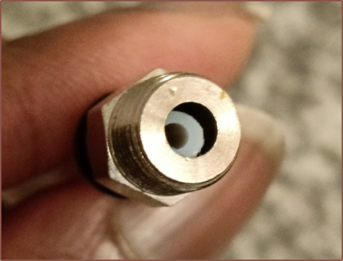
The first thing that happened is that nothing fed in. I opened the ptfe's and only one even got in. The other 3 got caught.It turns out that the bowden coupler itself has a catch that the ptfe will catch on unless it's effectively perfectly straight.I already expected that whatever bowden coupler I used in this hotend would cause issues sooner or later, but I wasn't expecting before I've even gotten a print out. Expected ratios for vtools (starting at T0 = 1.):
- 1/0/0/0
- 0/1/0/0
- 0/0/1/0
- 0/0/0/1
- 0.5/0.5/0/0
- 0.75/0.25/0/0
- 0.9/0.1/0/0
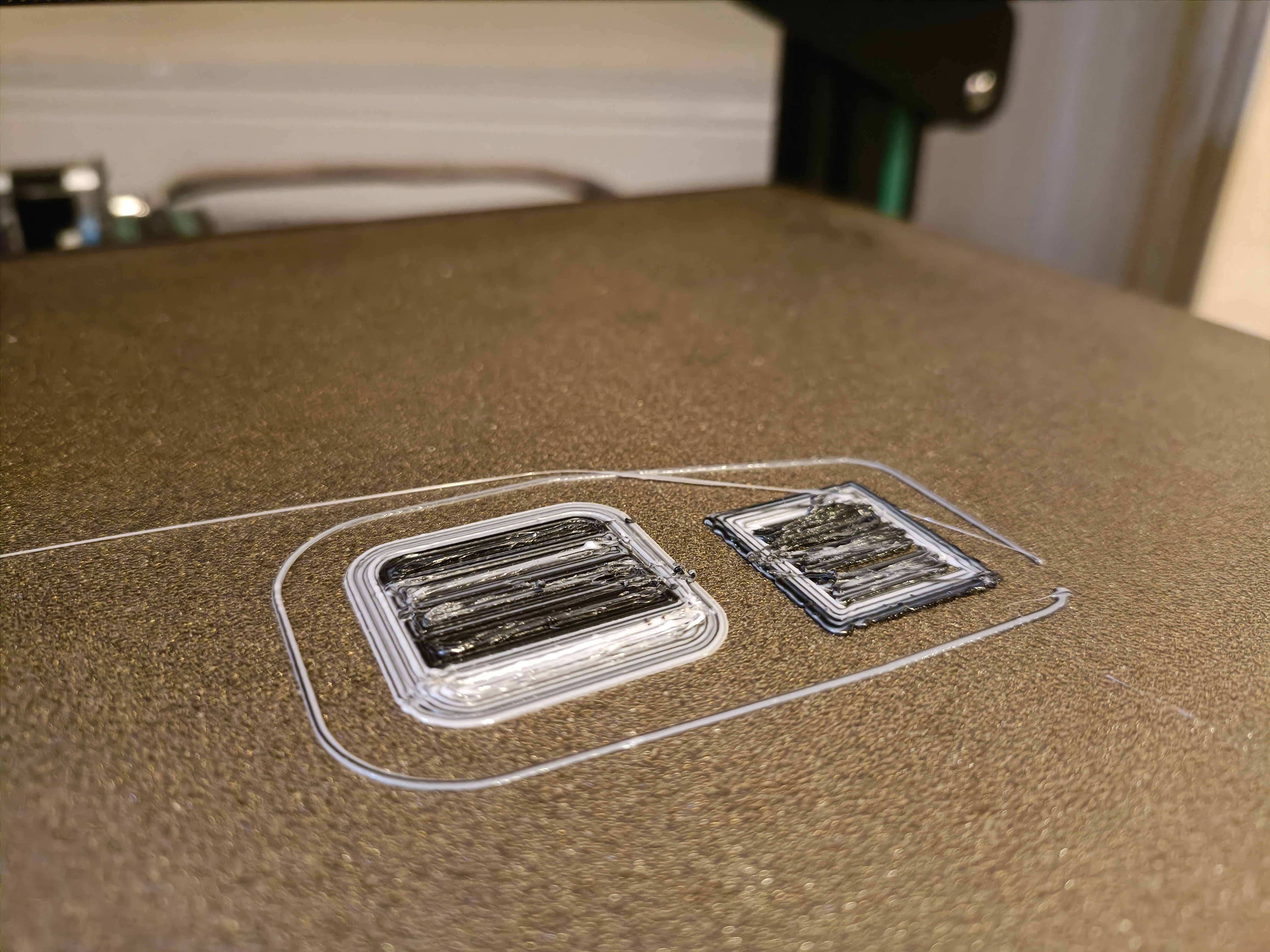
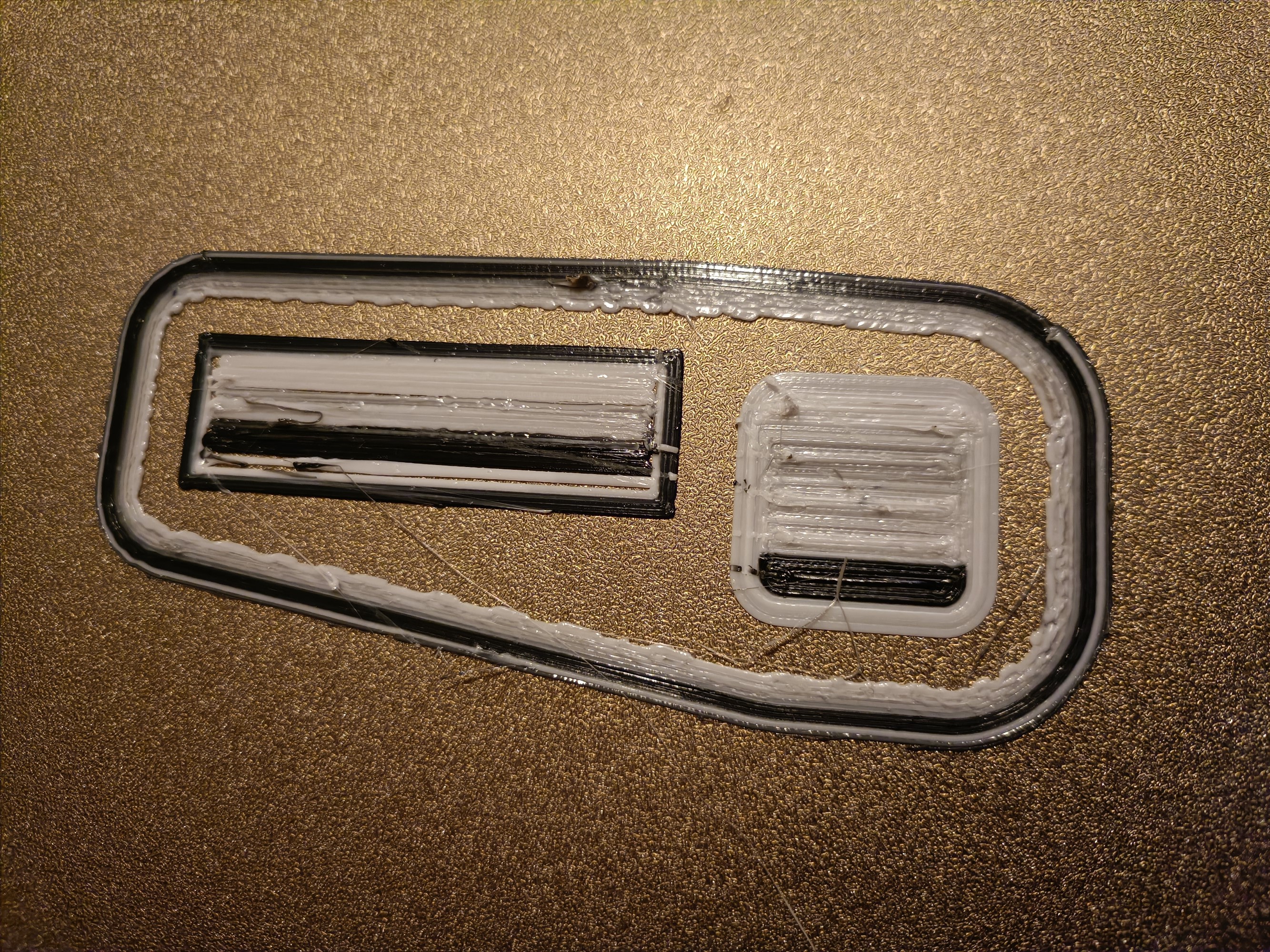
This is the first result:
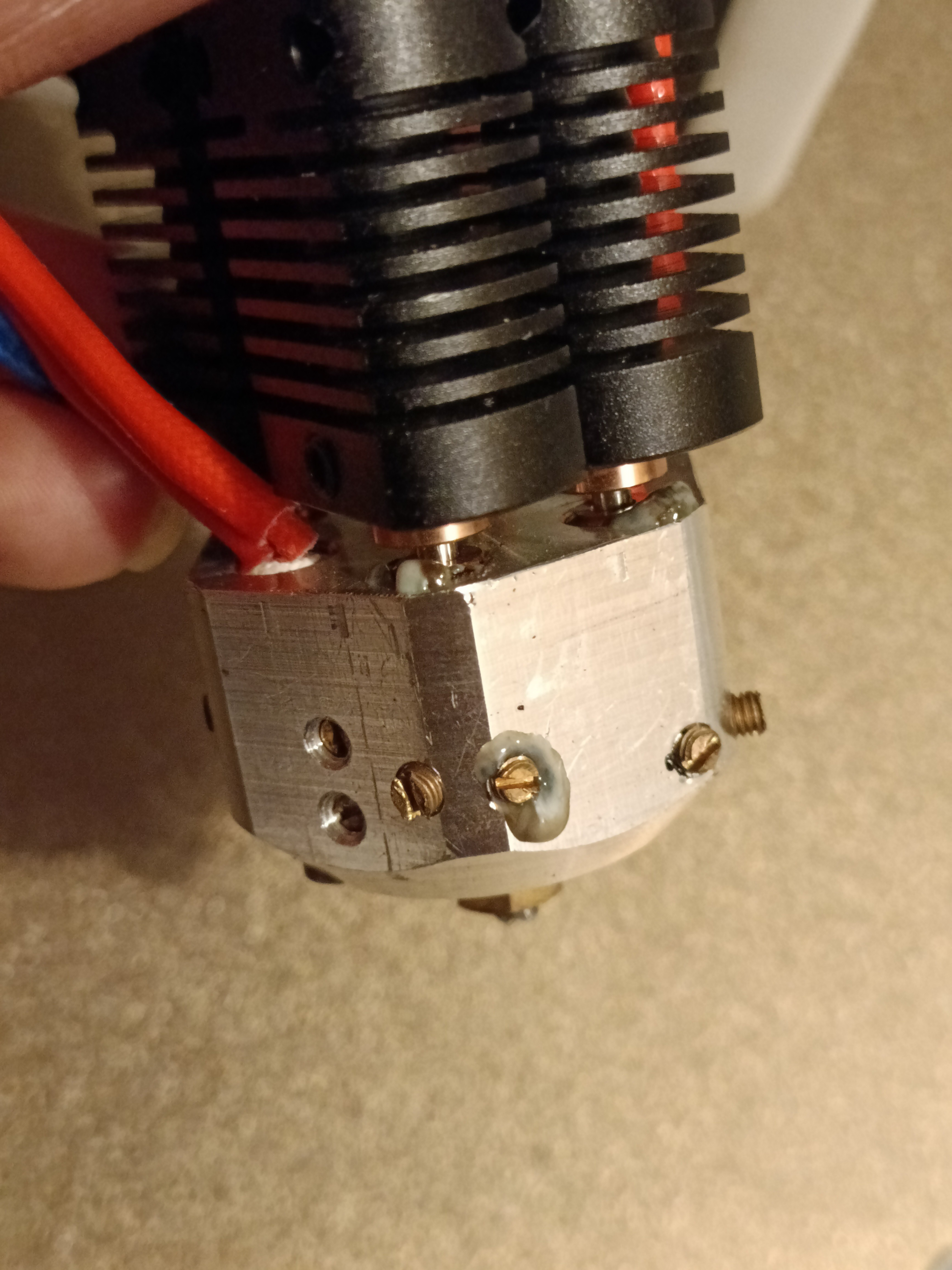
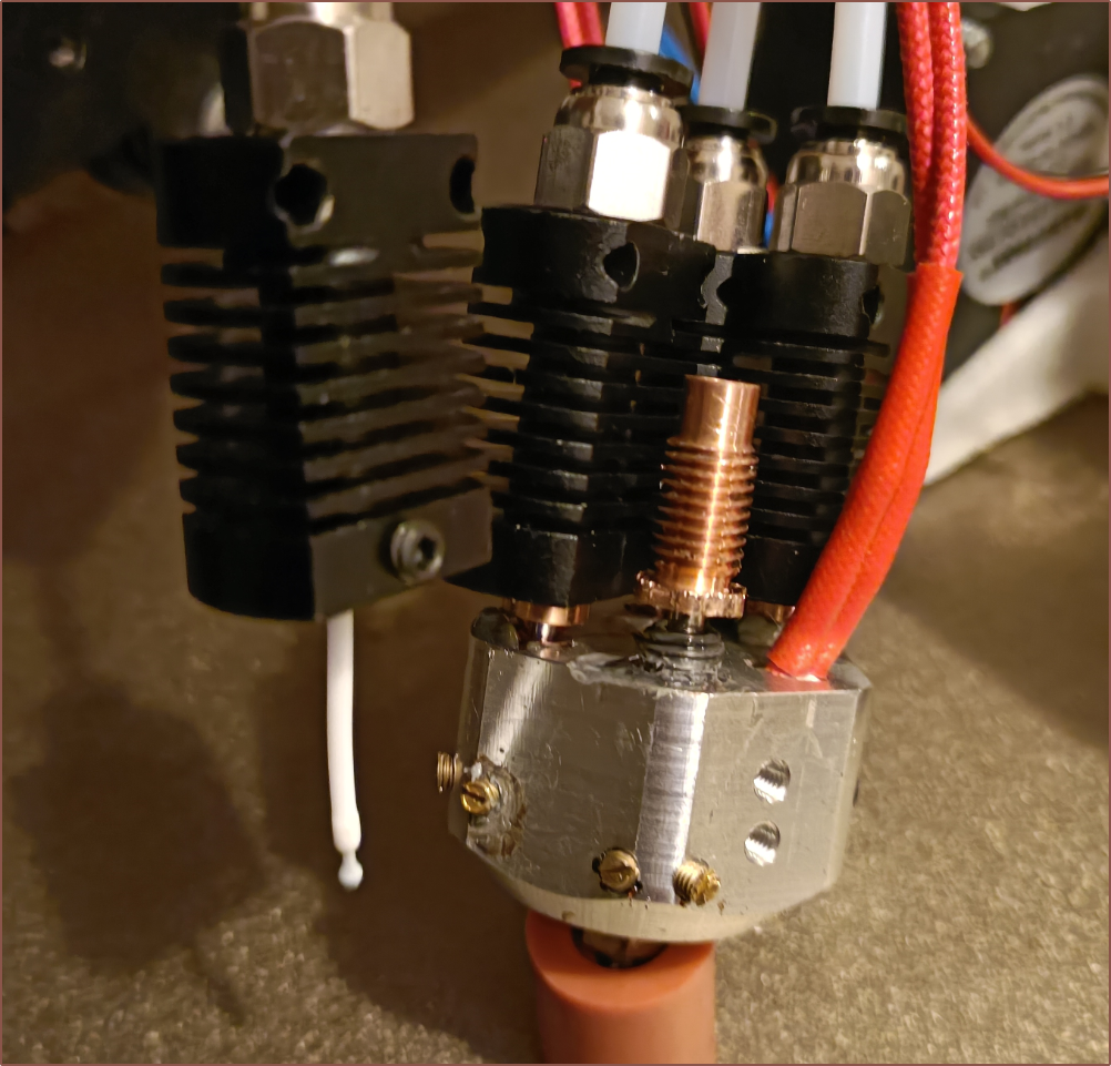
This is the hotend after the print:
I looked at the virtual tools after and for some reason, T0 was set as a 9:1 ratio. Also, the wipe tower volume was too small to get proper transitions.
Second print test
I thought that I might as well test to see if the heatbreaks just needed to be tighter or something, so with the help of one of the silicone levelling spacers, I swapped it out:
Then I sliced with a larger purge amount and even increased the amount of skirt length for extra measure:
I found out something about M165 that it sets the mix for the active extruder (it's not a 1-line version of M163) and so added it to the filament gcode of each virtual tool (instead of the start gcode).
Expected ratios for vtools (starting at T0 = 1.):
- 1/0/0/0
- 0/1/0/0
- 0/0/1/0
- 0/0/0/1
- 0.7/0.3/0/0
- 0.8/0.2/0/0
- 0.9/0.1/0/0
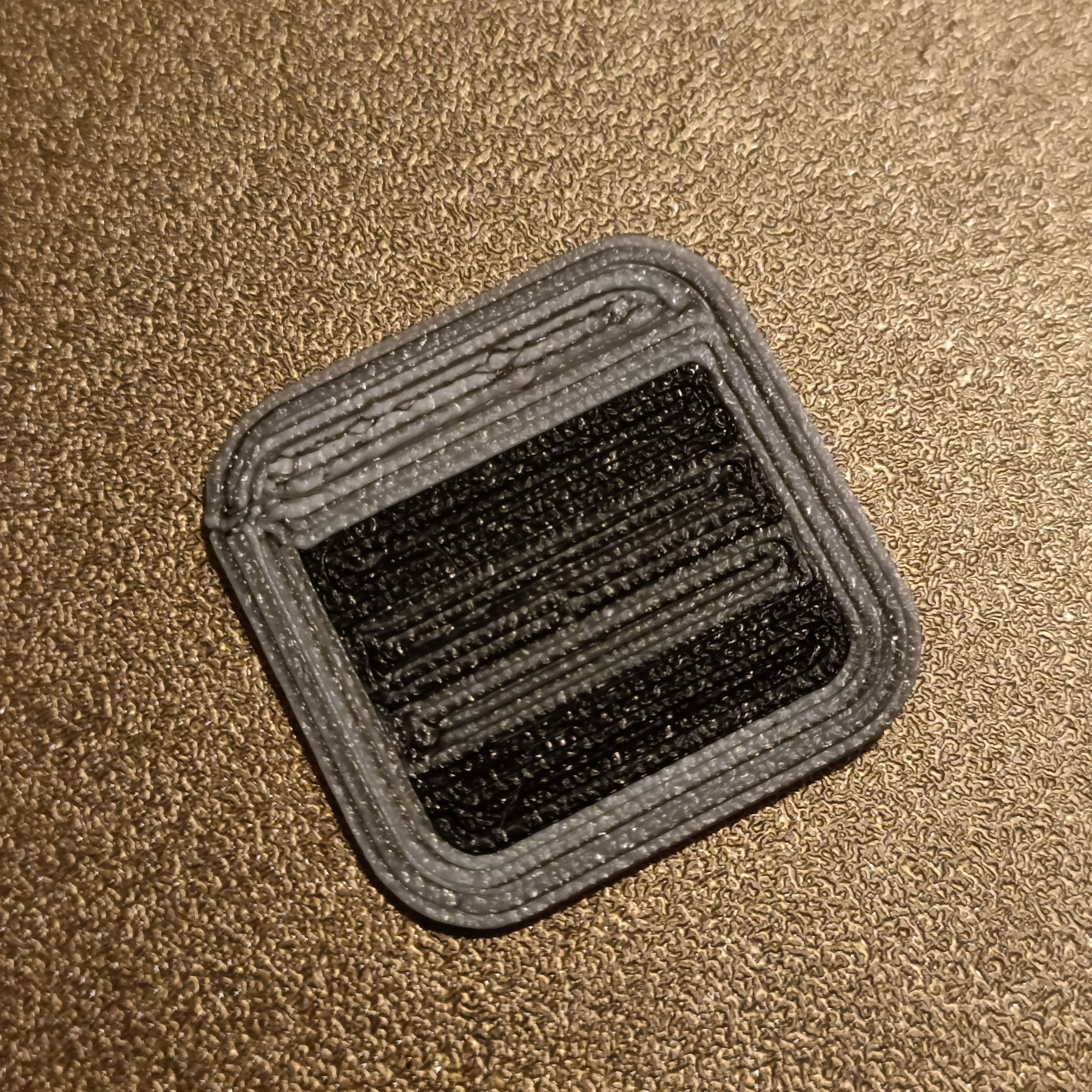
This is the result:
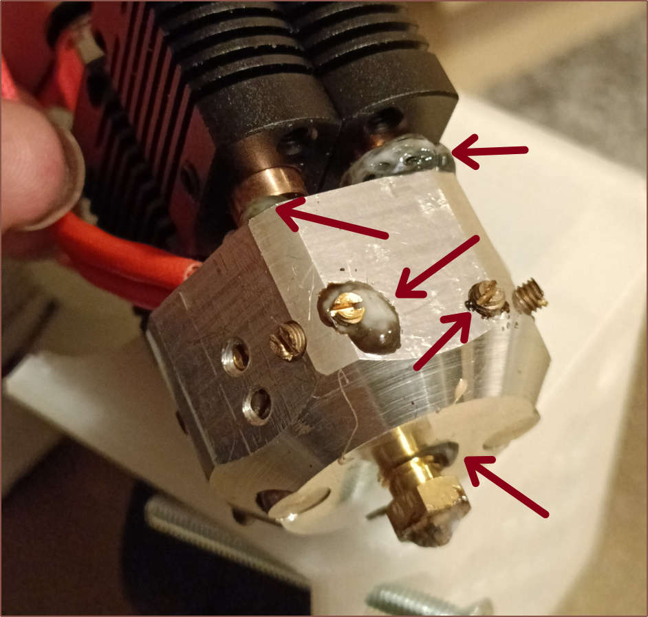
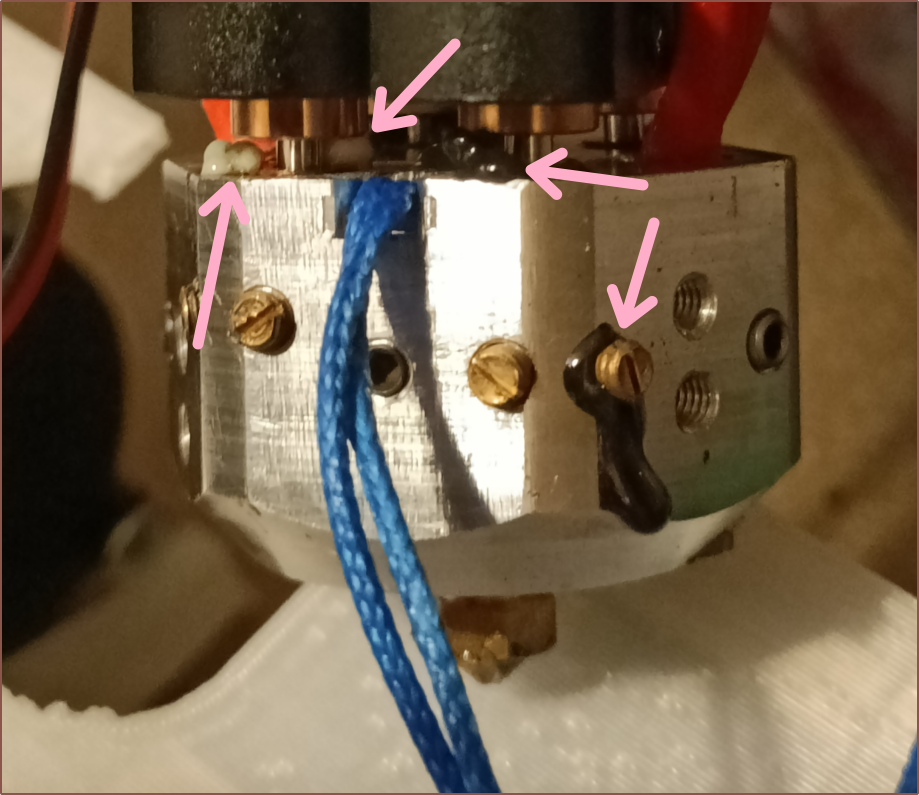
The hotend was in an even worse leakage state, with the experimental V6 heatbreak being awful:
Unlike the other 3, the filament was stuck in this one even when heated to 160C. I did manage to get it off though:
Conclusions
It's interesting that the first test was too black and the next test seemed kinda white. In terms of mixing, the results seem inconclusive. What I expect is that the overextrusion I observed had something to do with it. It could also be that material went in places it wasn't supposed to go, which also made me realise that I'm actually trying to get a "controlled leak" through the nozzle orifice and nowhere else. I saw some research a bit back which suggested that hotends work at 2MPa when printing, so it's more understandable how some can slowly ooze out.
Even the nozzle and coaxial-insert threads are starting to leak now, which is not something that future machined designs have addressed. The deckingman approach, which is a machined-flat mating surface and plates where the M6 threads are tapped and then screwed ontop, sounds like the method to go, especially with a printed heatblock solution.
Also, I certainly need to be using compression fittings or that cool brass heatsink seen in the BotObjects 5-in-1-out hotend.
-
[M][T] Machined 6-in-1-out not geometrically possible?
01/22/2024 at 06:04 • 0 commentsYou know how the CR600S got its name? Well it's simple. With a large-at-the-time build volume of 300*300mm and my craving for speed, a 0.4mm nozzle installed in my CR-10 just wasn't enough, so I got a 0.8mm one. Whilst dramatically speeding up print times, the cooling requirements and at-the-time minimum printable wall thickness of 1.6mm brought it's own set of pain-points. Lastly, multiple months after trying to tune in a 0.8mm nozzle, I tried a 0.6mm and it was the Goldilocks zone. At that point, so many changes had happened to the printer that it didn't feel right still calling it a CR-10, so it became the CR 600 (micrometer) Series.
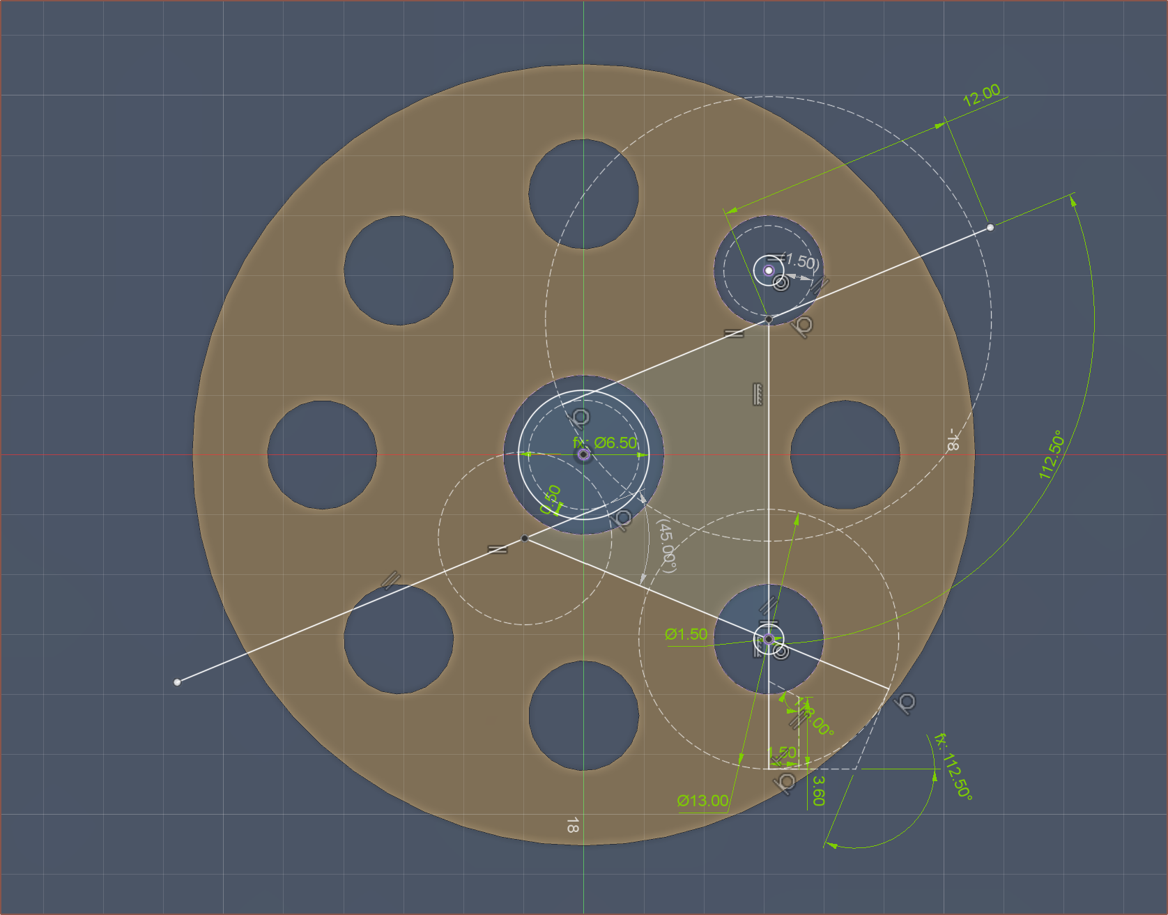
Anyway, I was wondering if the same could apply to the coaxial hotend. 4-in-1-out isn't quite there for the requirements of full-colour printing, lacking inputs for black or soluable support material, but 8-in-1-out needs a lot of extra plumbing. 6 could once again be the ideal balance. However, I'm starting to understand why Me In The Past gave up:
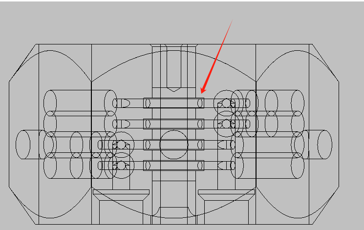
You see that circle with "1.50" in it? Yeah uh 1.5mm is also the radius of the hole plugs. In other words, there is 0mm of material between the vertical shafts and the ball-plug holes with an angle divisible by an angle derived from the following equation:
180 / ( Inputs + 2 )
Now there's probably a solution if you disregard this and tell the CNC lathe to just mill all the specific angles, but that increases complexity compared to the 8-in-1-out that just needs 10 angles. Any unused paths can just be sealed away with an M6 grub screw. Another solution may be to remove the centrifugal design.
Speaking about that 8-in-1-out, I just found out that the minimum distance between inputs was only around 8mm or so, and any PTFE coupler I'd use would need at least 10mm, so I've spaced them out more. The diameter only increased by about 6mm (aka diameter = 46.3mm).
Also, I'm thinking of using the "high flow" version of the heatbreak-heatsinks so that the material can be pre-melted before going into 1.5mm diameter shafts, further reducing the amount of molten material actually inside the coaxial block. It's also reduced so that the minimum wall distance can be increased.
I've also changed the M6 undercut so that it uses the same tool as for the internal grooves. All groove depths have been reduced to 0.75mm.
Minimum wall distance is 1mm:
This also applies to the internal grooves, reducing the length by 1.4mm to 29.0mm. This also means that the insert is 23.5mm, likely meaning that an M8x25mm grub could be used as the stock material. I also got rid of the flat face for the thermistor (see bottom left of image below).
Another thing to mention is that a 6mm bore is the minimum diameter geometrically viable, meaning that an M7 thread is the minimum that can be tapped. Thus, without having to get custom nozzles, either the dual-heater-zone strategy or a custom thread-reducer part is required.
-
[C] Setting up Marlin Firmware
01/21/2024 at 17:00 • 0 commentsI've spent the past 2 days setting up Marlin and TouchScreenFirmware. I decided to try and set it up for the dual heater zone strategy just to see if it could even be done before I bothered to actually go down that path.
Here are the shownotes of things I learned:
- There has been an alternative heating method to PID in Marlin for a while that I've only now found out, called MPC. This reddit post shows the difference and it looks like the superior method.
- Marlin considers a mixing extruder as 1 hotend, even if 2 thermistors are specified. This causes a tad of an issue with MPC and I needed to add and modify some things to get around it.
- To use Marlin Mode on the TFT, the EXP cables are still needed. This means that, had I actually tried using an 8-in-1-out, I wouldn't be able to use the Octopus Pro v1.0 I already have and instead would have to get something like a BTT GTR (I don't think anything else other than a Duet would support >=11 axis)
- Additionally, it seems that Marlin only supports 6 mixing extruders at the moment.
- Thus it really sounds like the strat would've been a Manta M8P V2.0 + CB1 + Fysetc AIO and Klipper, or something to that effect.
- C5, 523 Hz, sounds ok on the buzzer
- The Octopus Pro doesn't need the SD card after flashing, meaning I don't have to sacrifice a £3-from-AliExpress, 32GB microSD.
-
[A] CNC price keeps increasing
01/19/2024 at 07:21 • 0 commentsSo, to recap, here's where I started:
That fell through because there was a lot of improvements that needed to be made, and when I went back:
So, obviously, I was like "If I'm paying that kind of price, I should make sure it's the best it can be", thus I designed a version with my off-centered idea that I never got quoted. I then decided to model and send the 8-in-1-out version:
That fell through as that's when my subconscious price limit started to kick in, especially with the more expensive heatsinks needed.
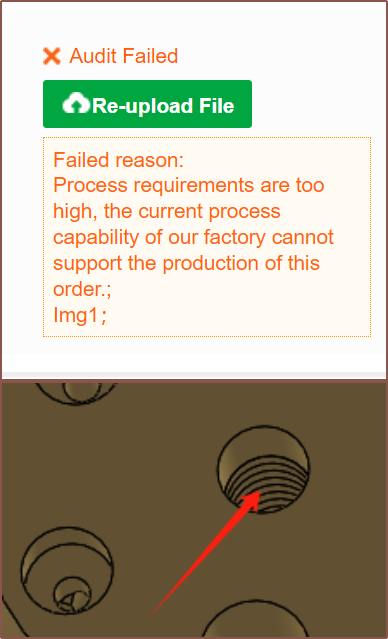
Now it's today, when I realised that I never got that 4-in-1-out off-centered design quoted. This was also the first one that featured the stainless steel ball-plugs over the grub screw design. Well I sent some variants through and I got this:
I'm like "Okay...? This is new." and send in a version with a 6mm internal bore (like the 8-in-1-out) and reduced the groove depth from 1mm to 0.75mm just in-case:
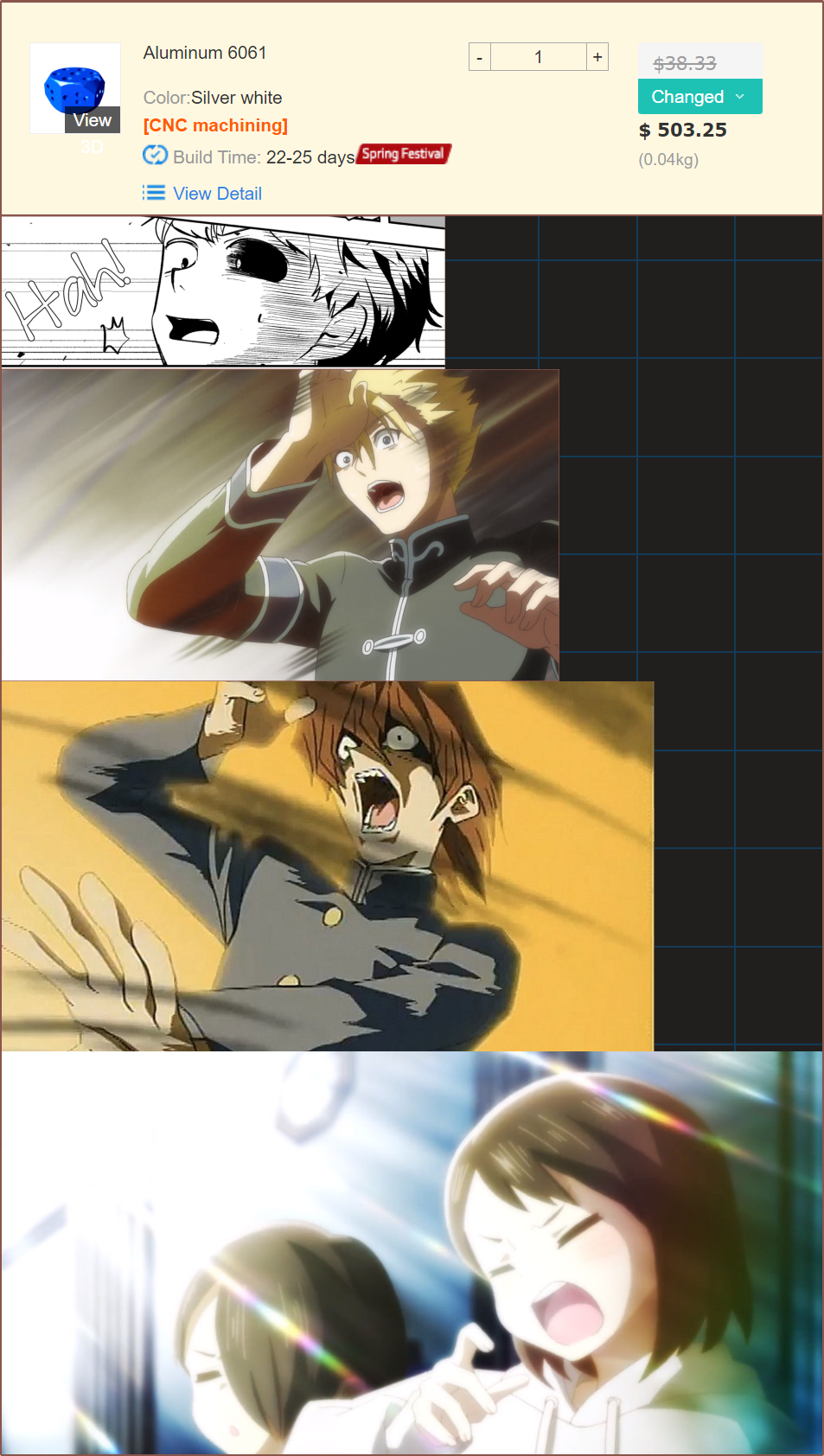
The result?
I can only assume that the workers checking the 3D printing / CNC files at PCBway have become more perceptive over time, better detecting unconventional geometry? Or maybe it's the "Spring Festival" tag, which I haven't seen before? I've never seen an over-20 day lead time before.
Maybe a better strategy for the Milled Coaxial Hotend is to see if I can get into contact with Mellow about this? Otherwise, the Printed Coaxial Heatblock is likely going to have to be good enough for science (if the 4-in-1-out machined heatblock I've got has an issue or I feel the need for more inputs).
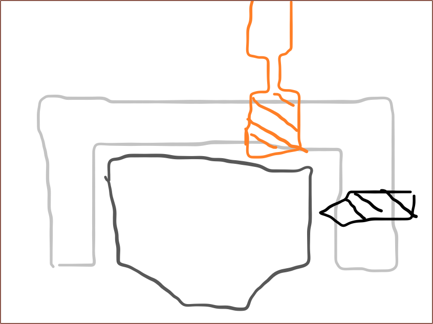
[07:40] I got more details. Seems that it's a tooling issue:
[0810] A rough estimate model of the 8-in-1-out printed heatblock is $64:
-
[T] Grub screw sleeve?
01/19/2024 at 05:34 • 0 commentsSo I was thinking about how Deckingman used a threaded mounting plate so that he could get the complete threads for the heatbreaks, and also wondering if costs could go down by splitting the complexity of a single part into multiple parts that, combined, cost less.
I then had the above idea, where there's a small coaxial-ization section and a metal sock that goes over it, where it's fixed in place by grub screws that both hold the sock in place and seal the internal channels.
I still feel like it'll probably cost more than just 1 single part though.
-
[P] Nozzle-block heatbreak fabricated and simulated
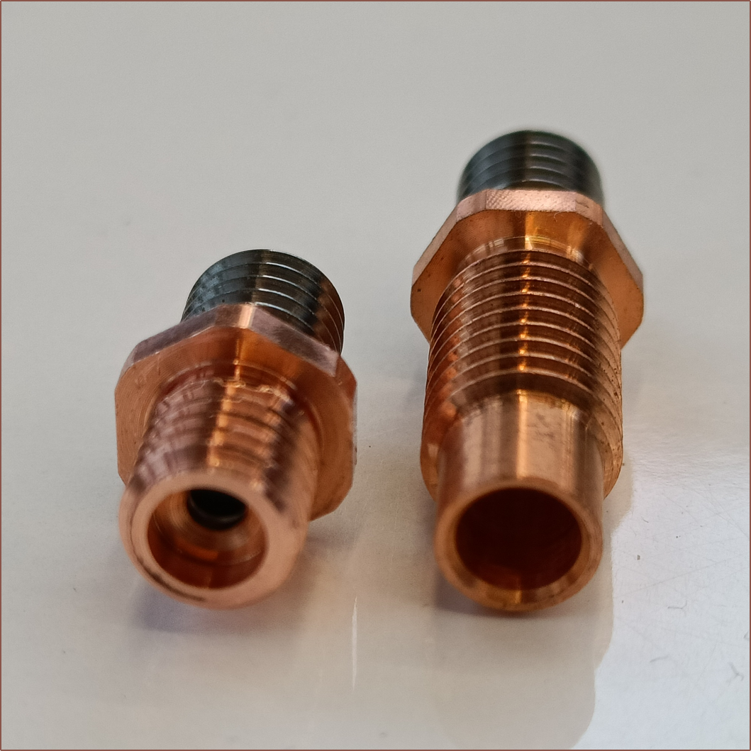
01/13/2024 at 02:44 • 0 commentsSo I was able to get a pack of 2 heatbreaks for £4.99 on Amazon and asked a university technician if it was possible to reduce the M7 thread to M6 and the length above the hex to 6mm. We were worried if the material was going to be too thin, but there was more than expected as the steel tube is a lot shorter (and a bit smaller) than expected. The 4mm inner bore goes much further into the heatbreak than I assumed:
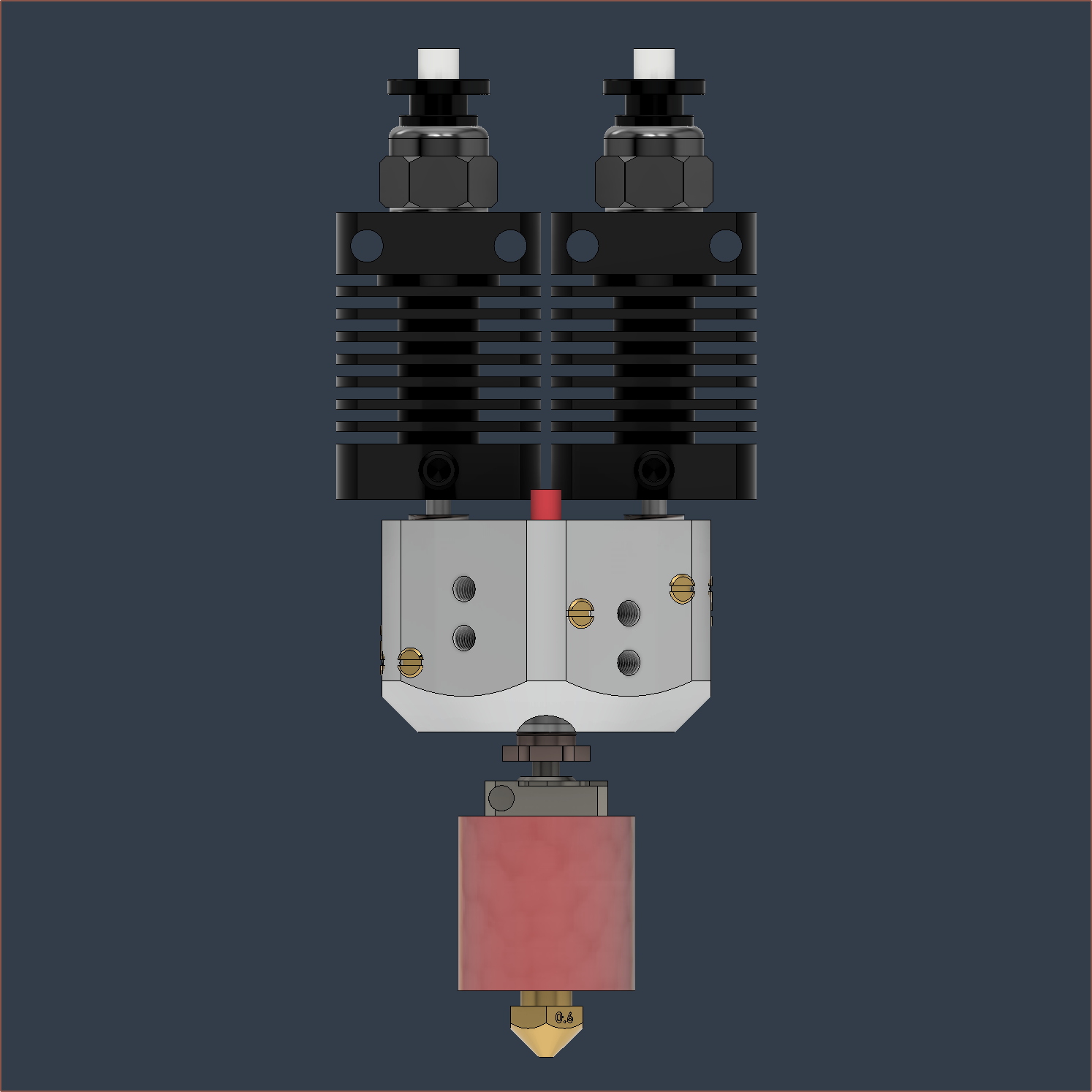
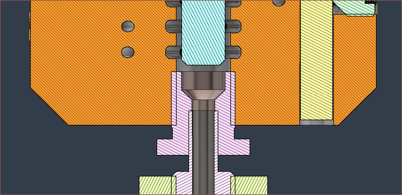
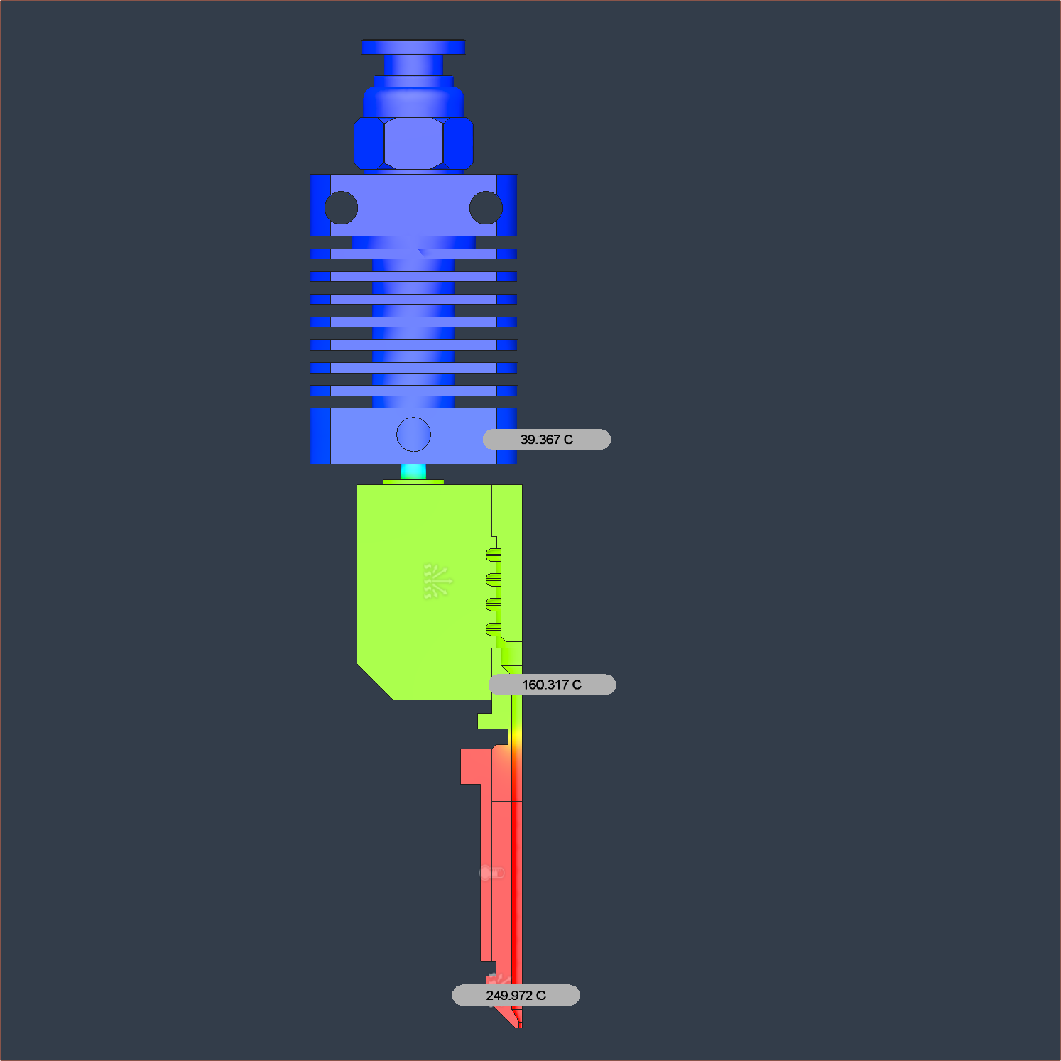
I applied the changes to the heatbreak CAD model and then digitally assembled the legacy 4-in-1-out Machined Coaxial Hotend and thermally simulated it.
I'm going to use the CHC Pro (possibly insulated with ceramic wool) I still have from #SecSavr Sublime [gd0036].
If this works, I don't think a more perfectly designed heatbreak could exist. I simulated 1/4 of the full model due to symmetry. I also got some PTFE thread seal tape, which I believe is the cheapest single thing you can buy on Amazon Prime:
Coaxial8or [gd0144]
Full-colour FFF? Multi-materials with unparalleled interlayer bond strength? Abrasives without abrasion?
 kelvinA














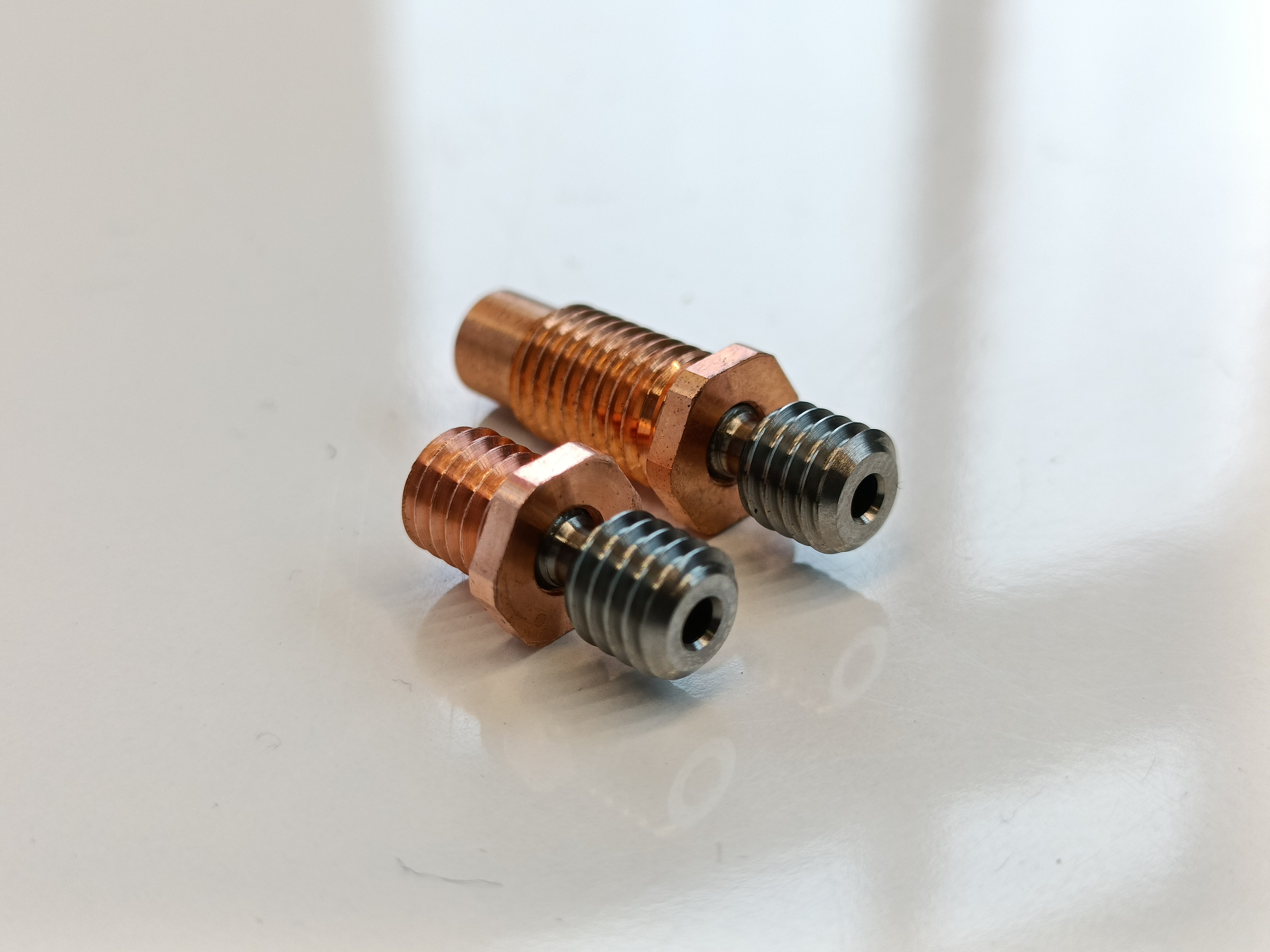 So I was able to get a pack of 2 heatbreaks for £4.99 on Amazon and asked a university technician if it was possible to reduce the M7 thread to M6 and the length above the hex to 6mm. We were worried if the material was going to be too thin, but there was more than expected as the steel tube is a lot shorter (and a bit smaller) than expected. The 4mm inner bore goes much further into the heatbreak than I assumed: