-
Converting breadboards to PCBs
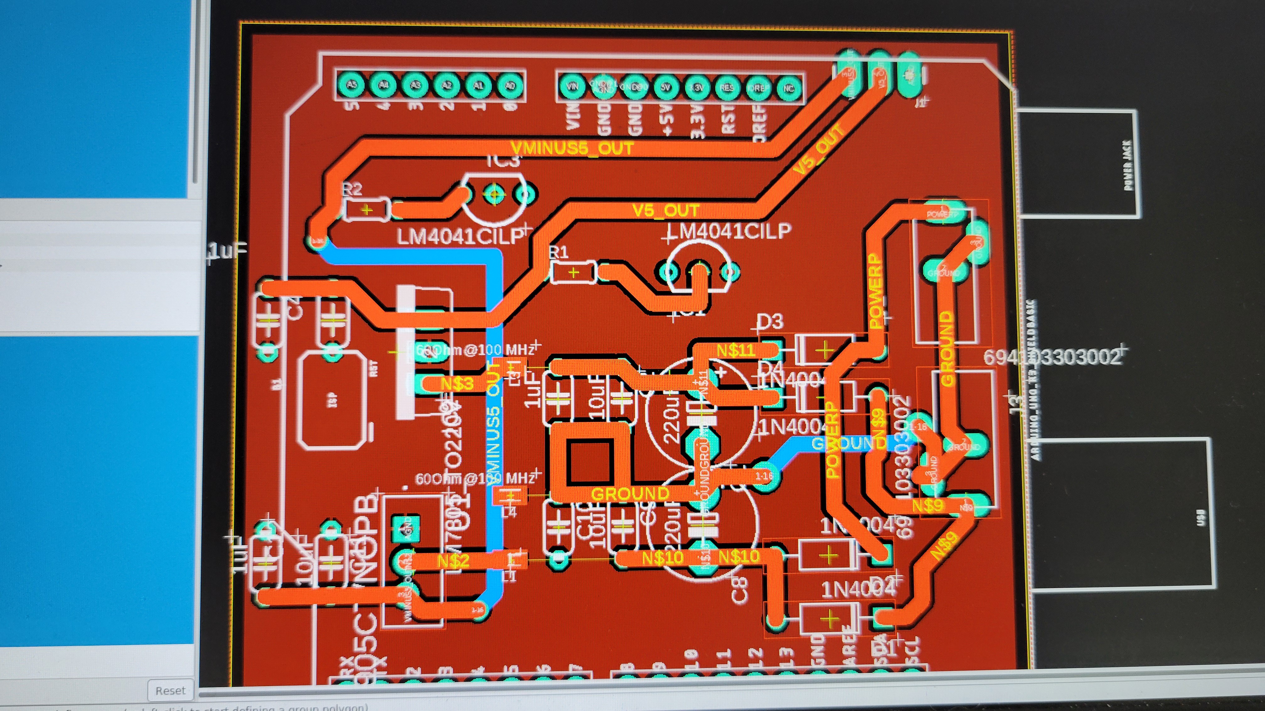
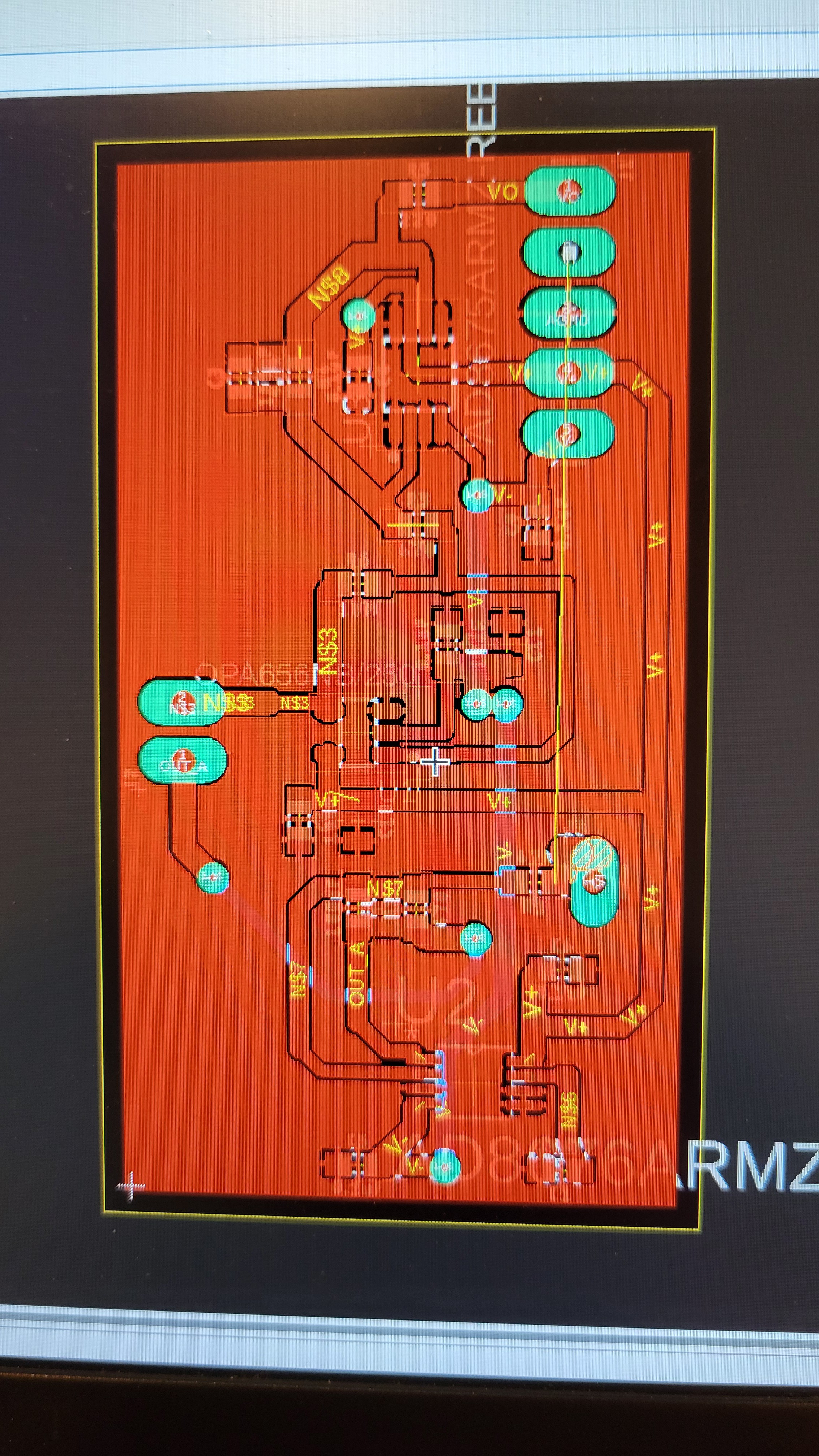
02/23/2024 at 03:13 • 0 commentsI've started to build a schematic of piezoelectric controller. I made schematic and layout. In my current version we use LM324N and it's quite old. We may switch to OPA4205 for better results. But for this version lets stay with the tested LM324N.
![]()
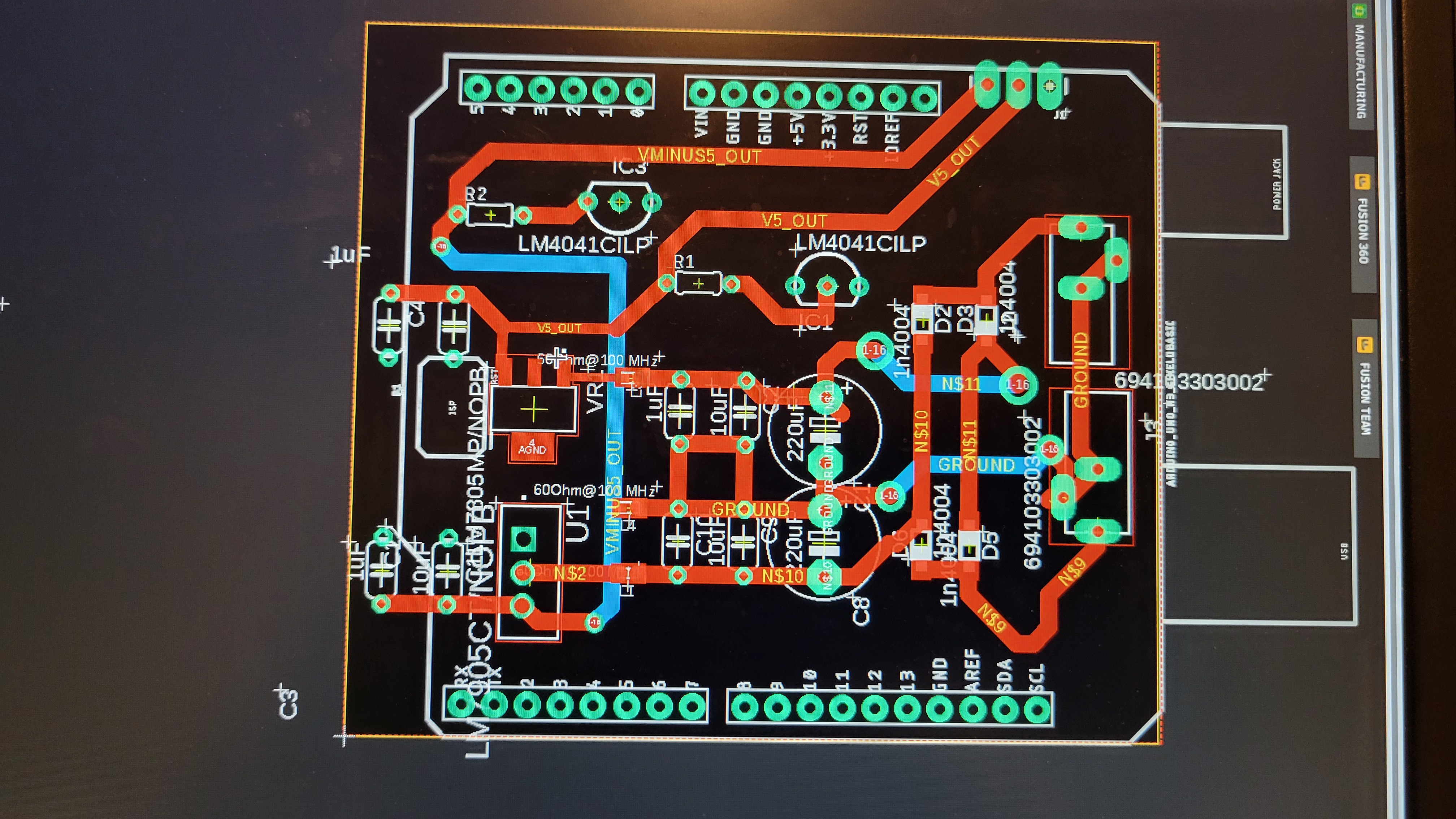
Made schematic/board of power supply board
![]()
Luckily I've noticed that the power pins are switched between those two boards.
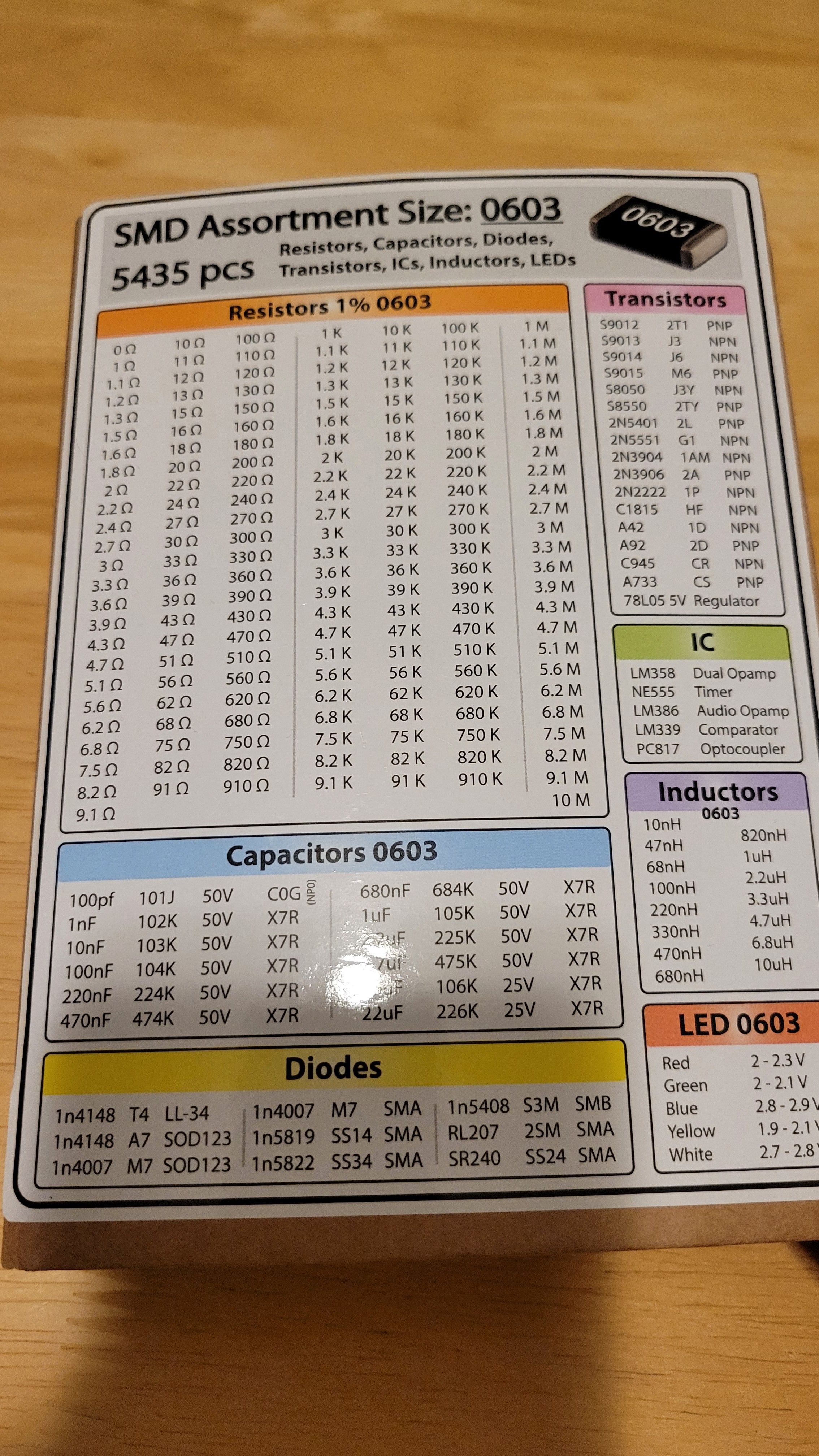
While fixing it, I've noticed that I use sime through hole components while most of the board are SMD (surface mounted device). The reason for that was to use the same components I've used in breadboard. Then the question rised do I have those components in SMD format?
Fortunately the answer is yes. I didn't buy those components I just got them while buying SMD resistors.
![]()
So I got diodes 1n4007 and lm339 comparator. Plus, I got 78L05 voltage regulator. Let's use those to make simple and cheap solution.
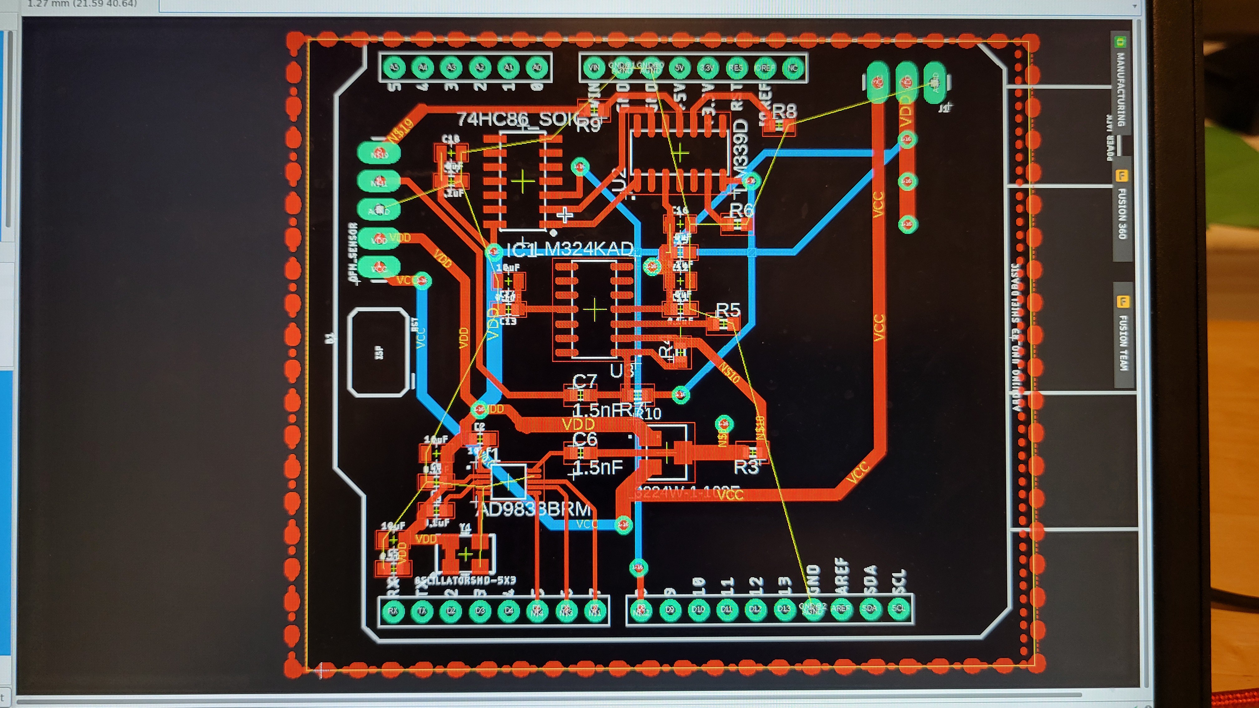
The new power board
![]()
Made input board
![]()
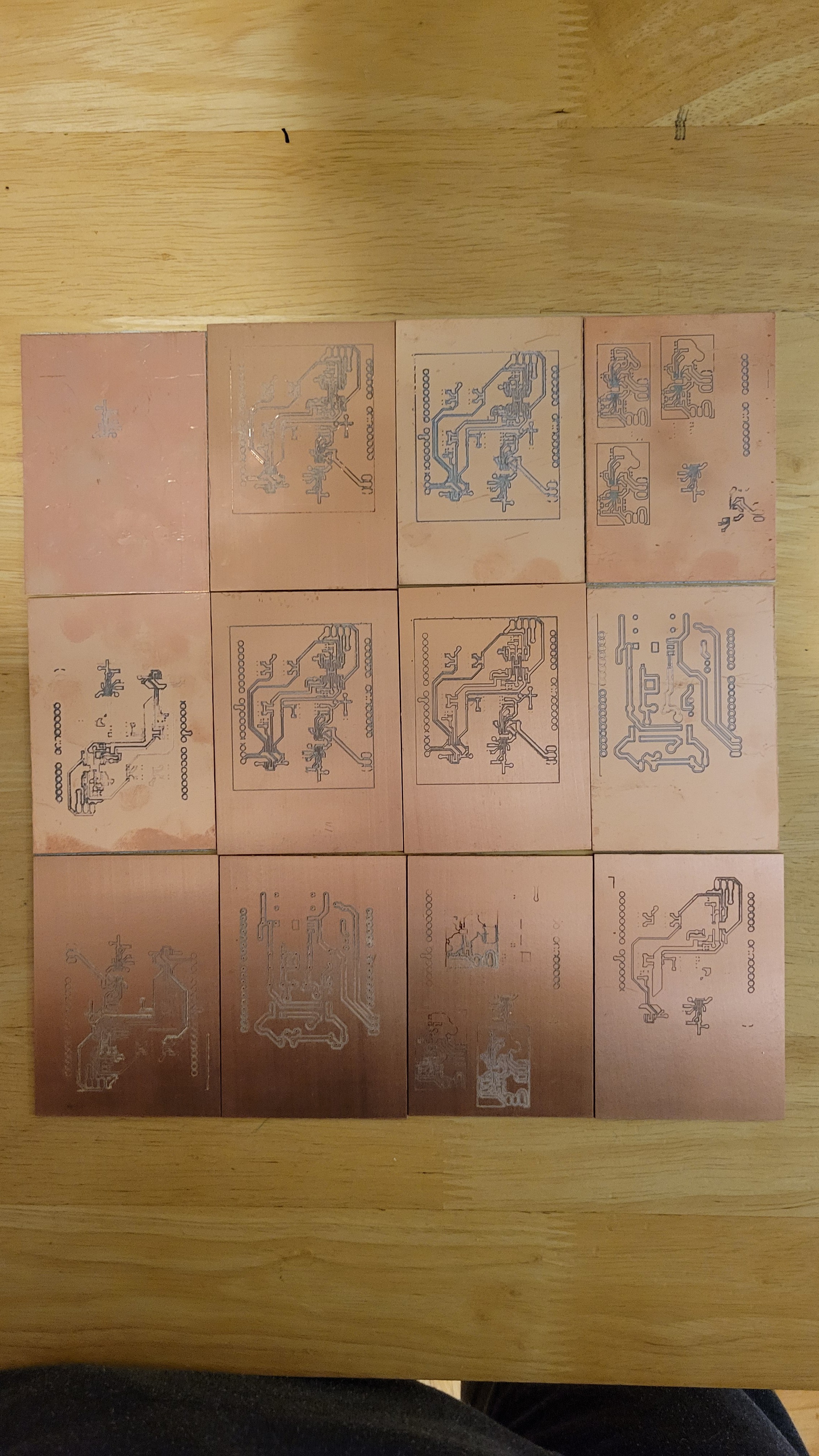
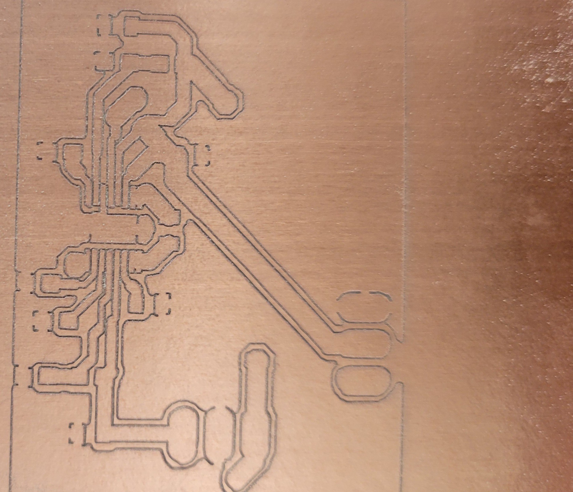
Started to create bare PCB boards using CNC, it took me at least ten attempts to get it right and learn all the tricks failing on each possible step.
![]()
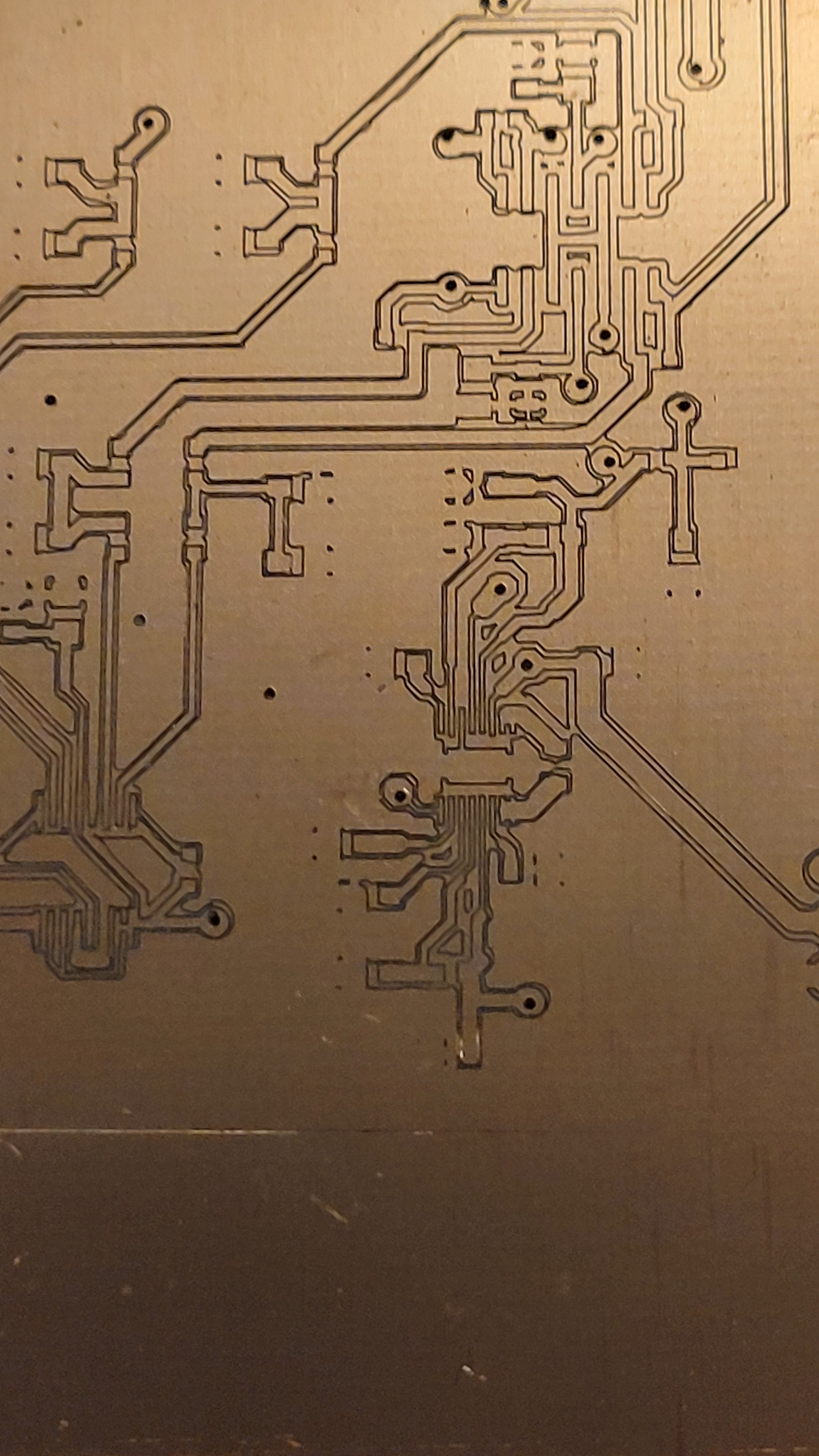
Luckily a pack of ten PCBs costs only six dollars. After few minor but important adjustments I got the desired result
![]()
Suitable for 0.5mm pitch ICs.
One good thing about making your own PCBs is how fast you can fix things once they go south.
Here I made a mistake by moving the Arduino relatively to power output.(Although I don't remember doing it)
![]()
It took me few minutes to create a new one with the correction.
![]()
Now we can start populating those PCBs with components
Slowly but surely, started adding components
![]()
Rectifier bridge works!
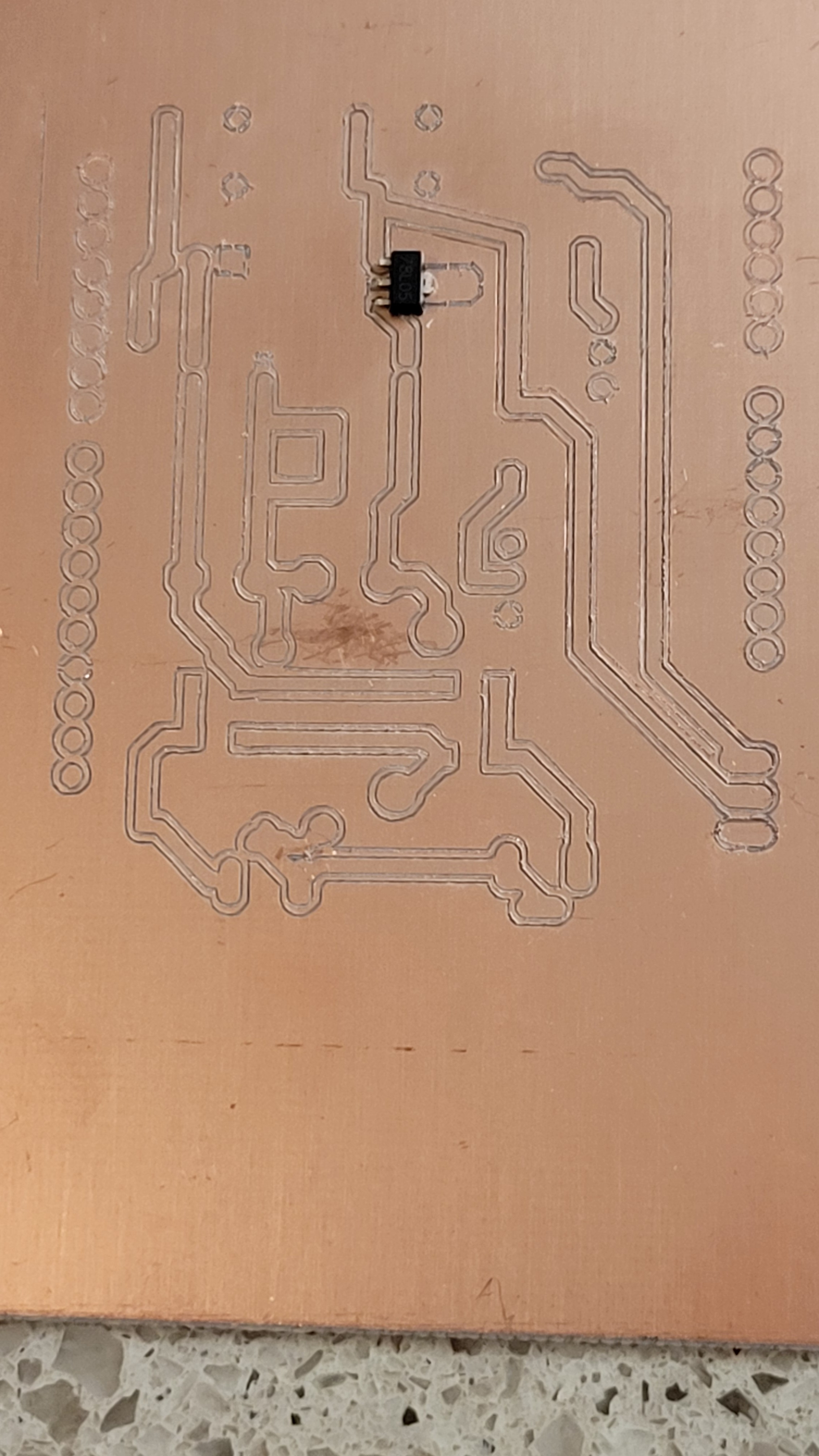
Added more components capacitors and L78L05 voltage regulator just to find that I used wrong layout much bigger with opposite pinout layout. Tried to reverse and make changes on the fly with Dremel. Ended up with bricked PCB. This should be the 'easy' one.
![]()
Luckily I can print PCB at home.
Ta-da!
![]()
It took me quite a while to be able to create 0.5pitch PCBs. I almost gave up...
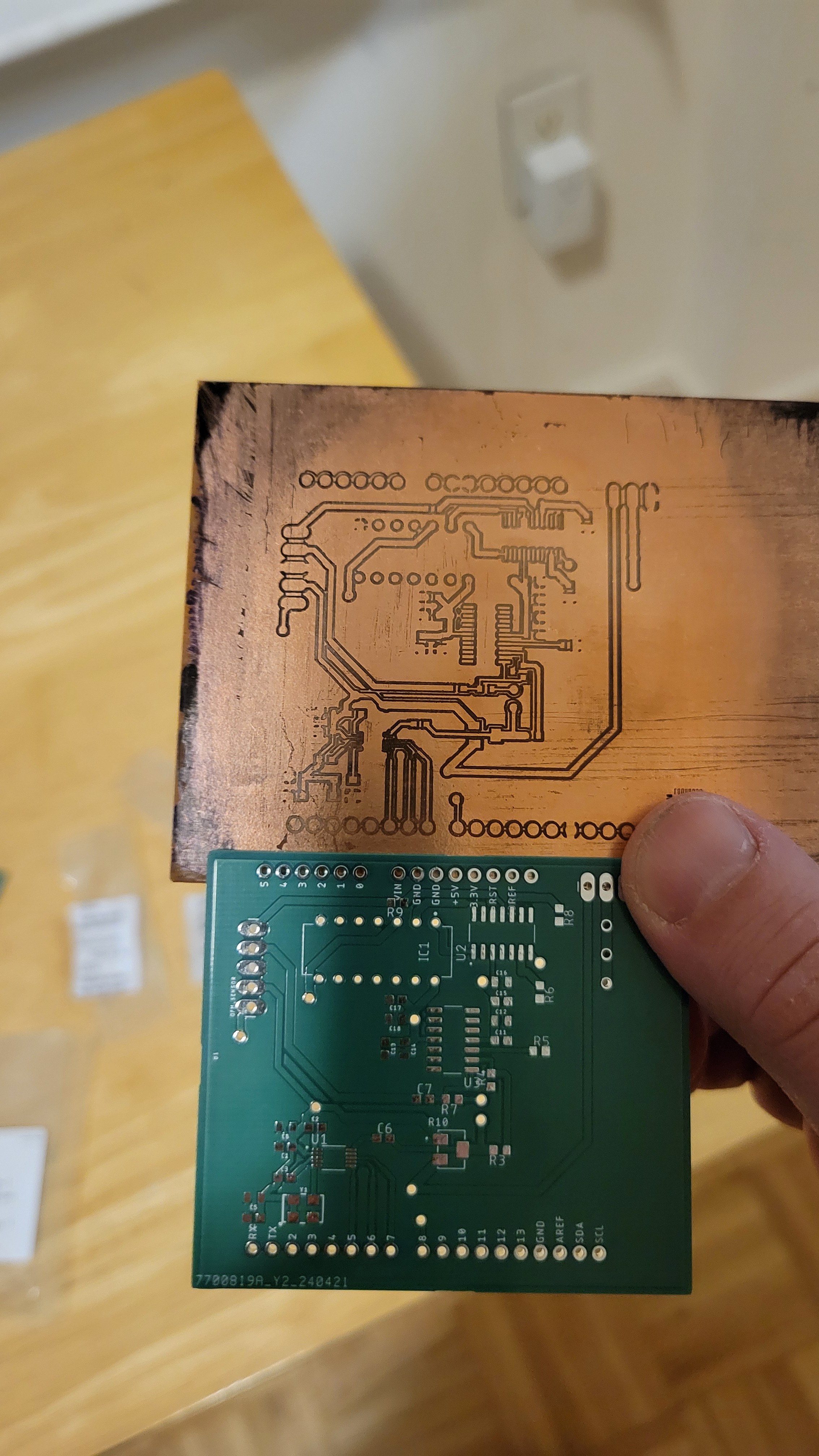
Ironically, I got my PCBs from China the same day I finally managed to create my own high quality PCBs. (I will tell it in another blog)
![]()
![]()
I must admit Chinese one looks much better :)
Anyways now we can continue 😃
* Added holes to power pcb,
* connected ac,
* Made rectifier bridge
* Added positive voltage regulator
![]()
Next negative voltage regulator
![]()
Got the positive and negative rails. How this song goes 'although I am not the prettiest thing you ever seen but I got my moments' 🤩
Finished with power supply PCB.
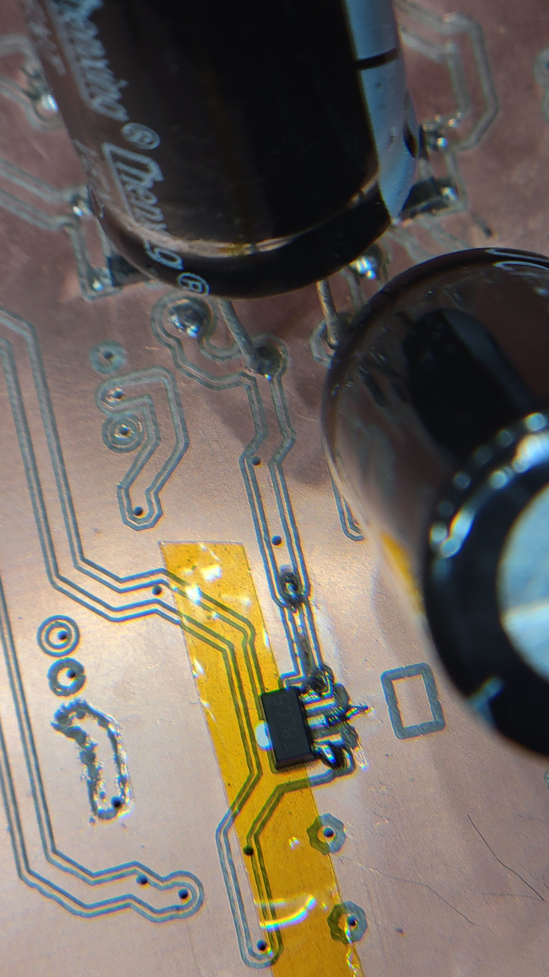
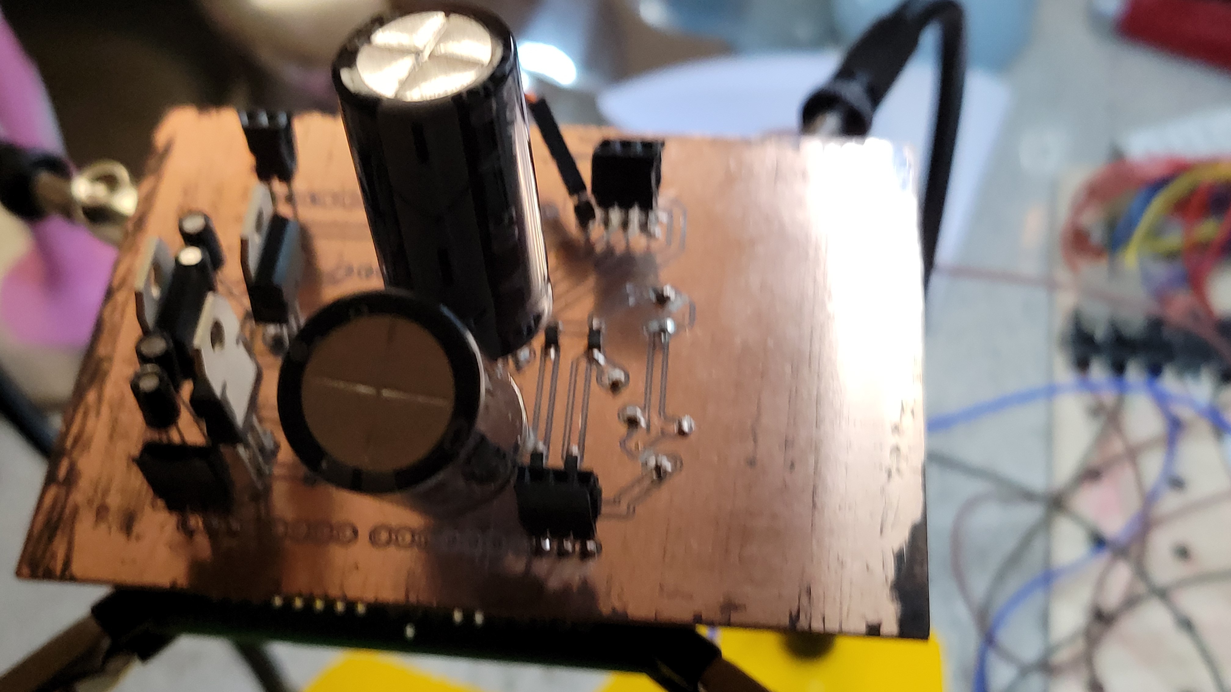
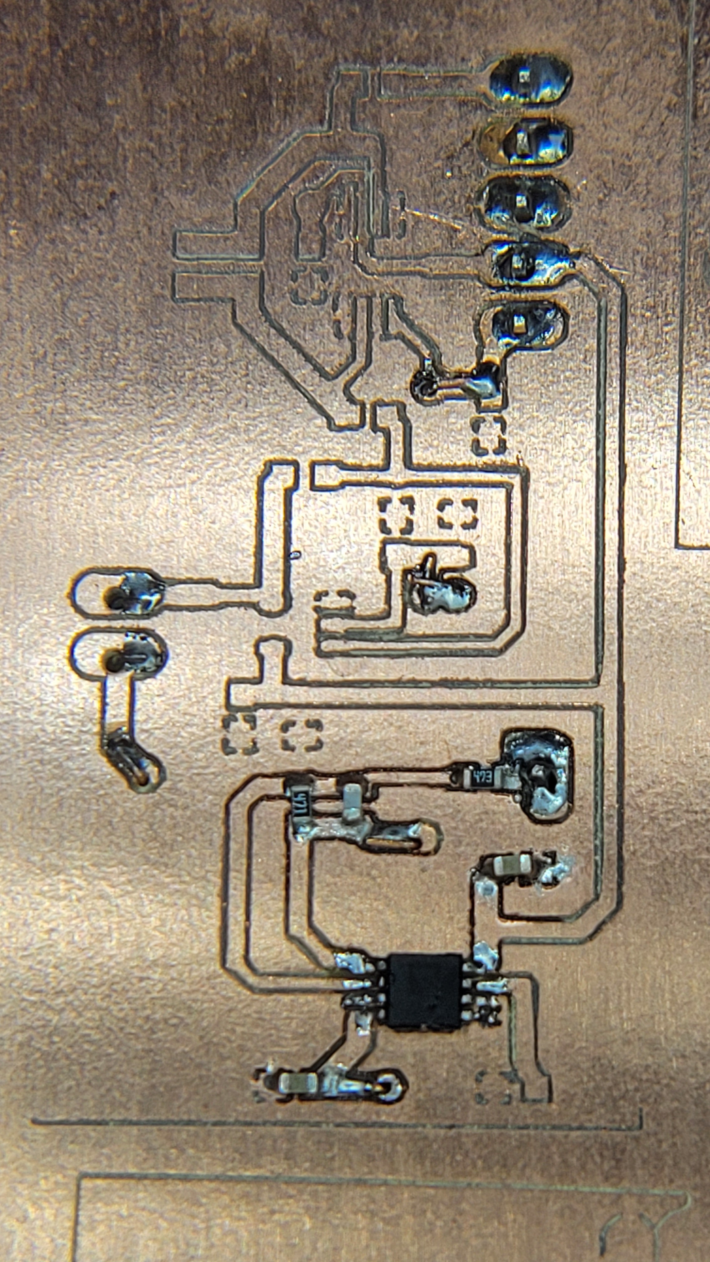
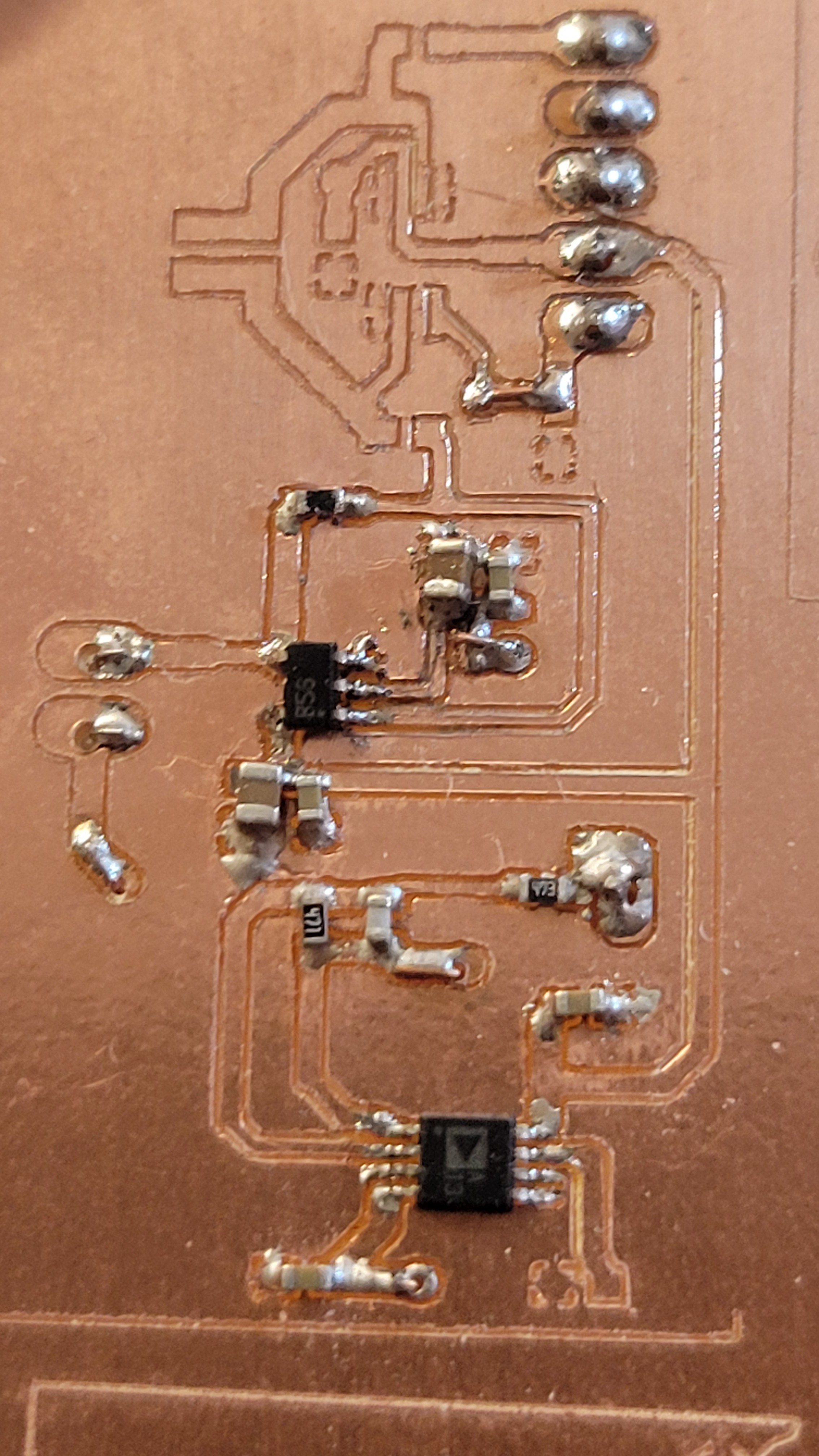
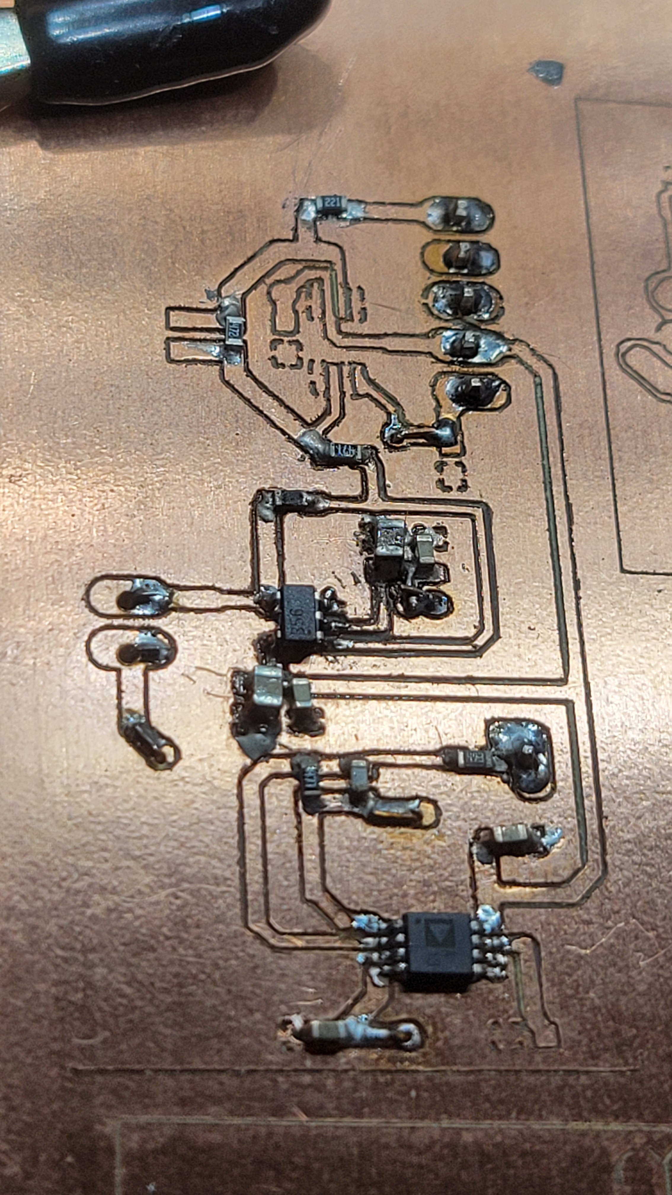
Started with piezoelectric controller, the hard part is charge pump. I didn't check it as it became too late
![]()
I must admit it much easier to work with a board that has solder mask and you don't risk of short-circuiting every component.
After checking the circuit it seems to be functioning as intended. Which was total surprise since last time it was such a pain in the neck.
Added DAC and fixed some design issue I had(forgot to add address pins to the ground)
![]()
Bad news I've just realized that my reference voltage is from charge pump instead of 5v. I hope I could make some fix on the spot. Otherwise another two weeks to wait.
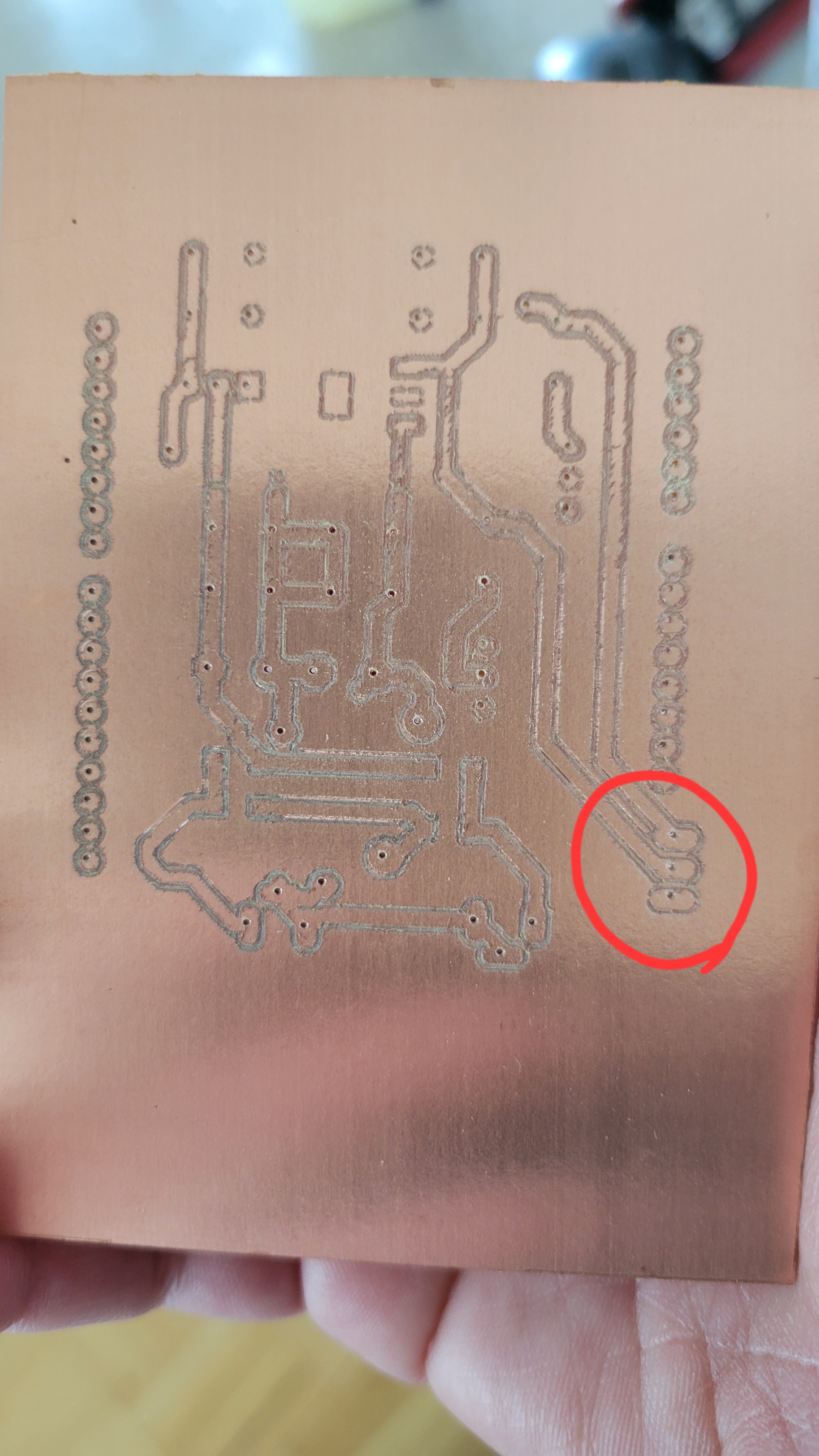
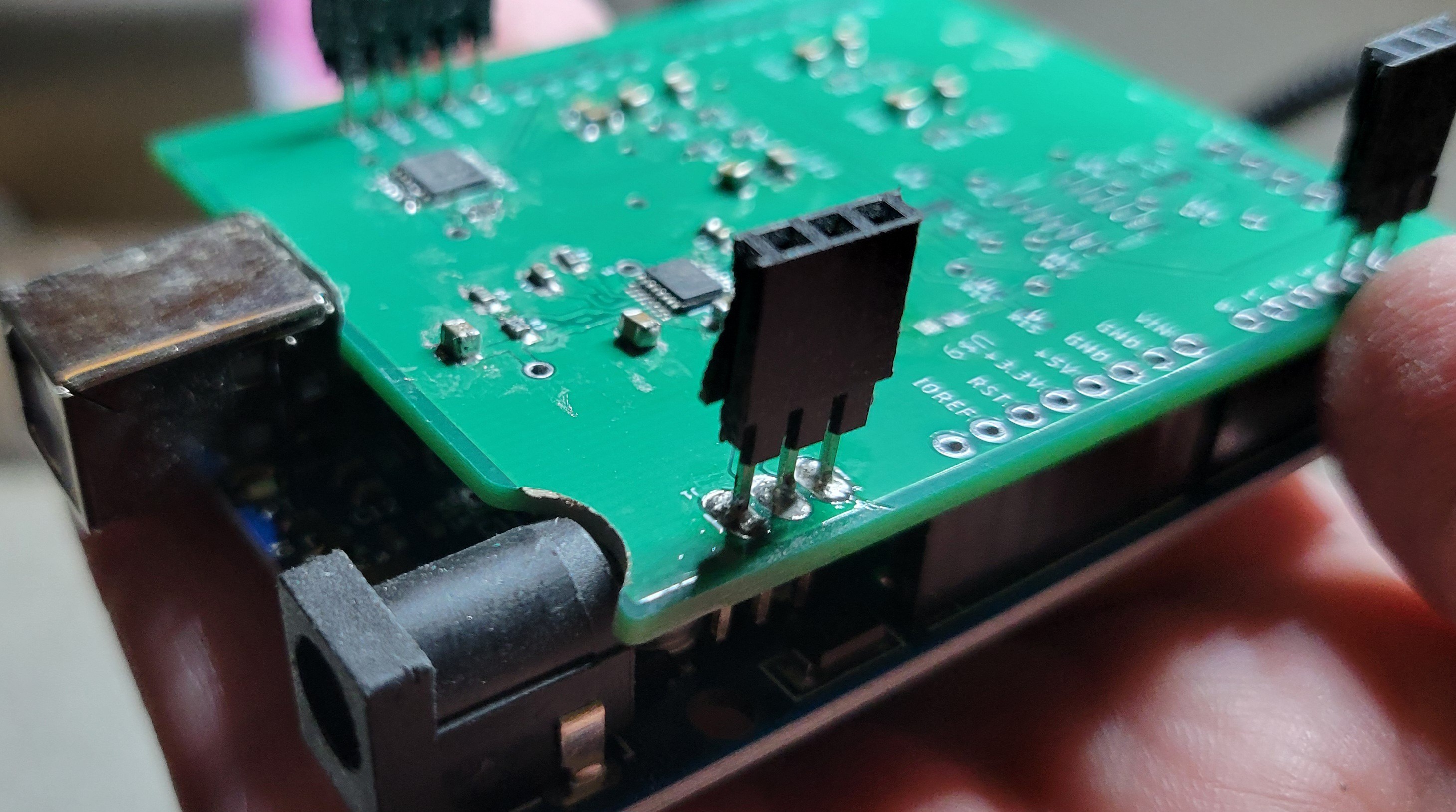
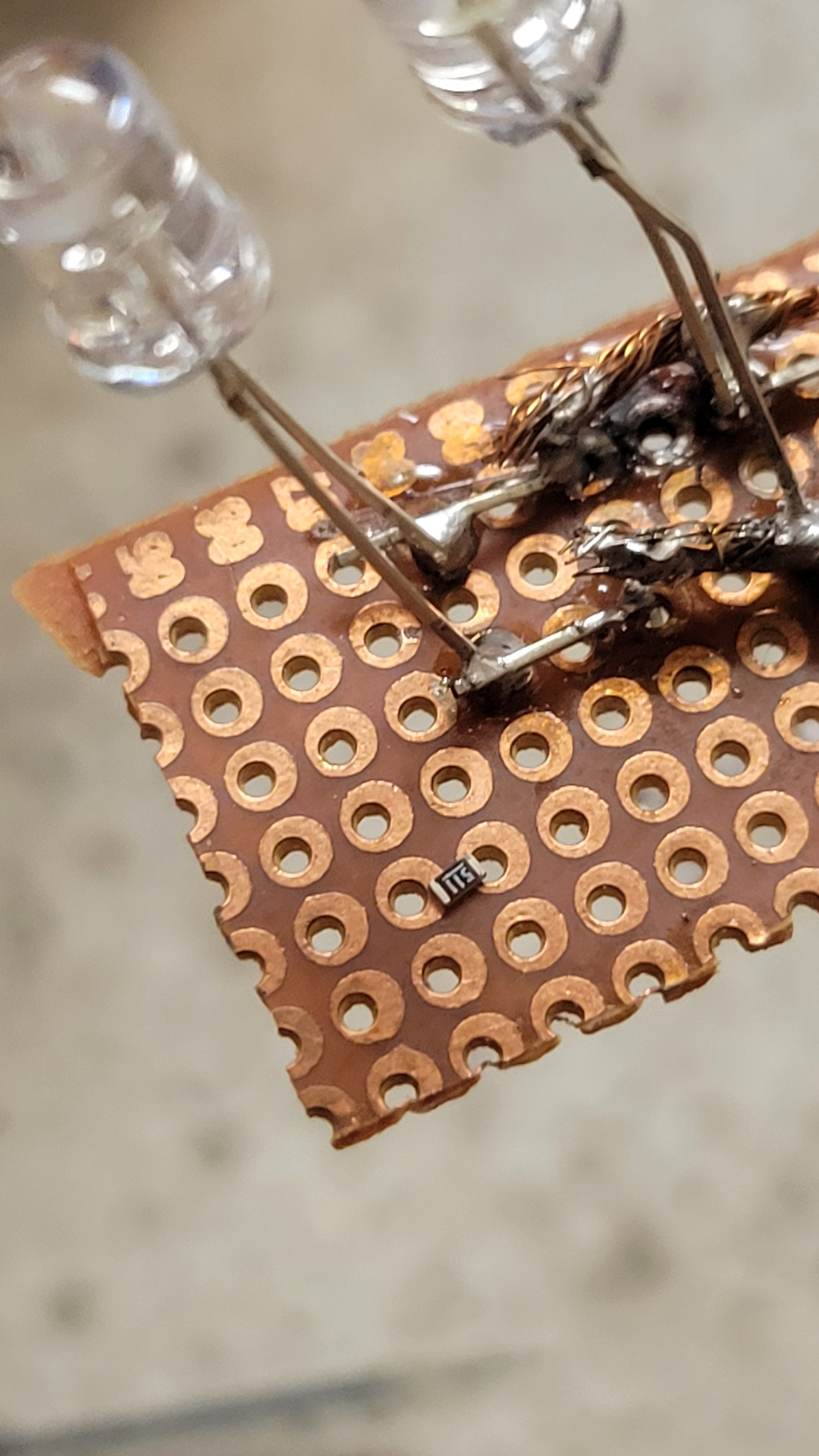
I felt like checking if DAC is working with all this unpredictable changes. Once I tried to connect I found that it doesn't fit
![]()
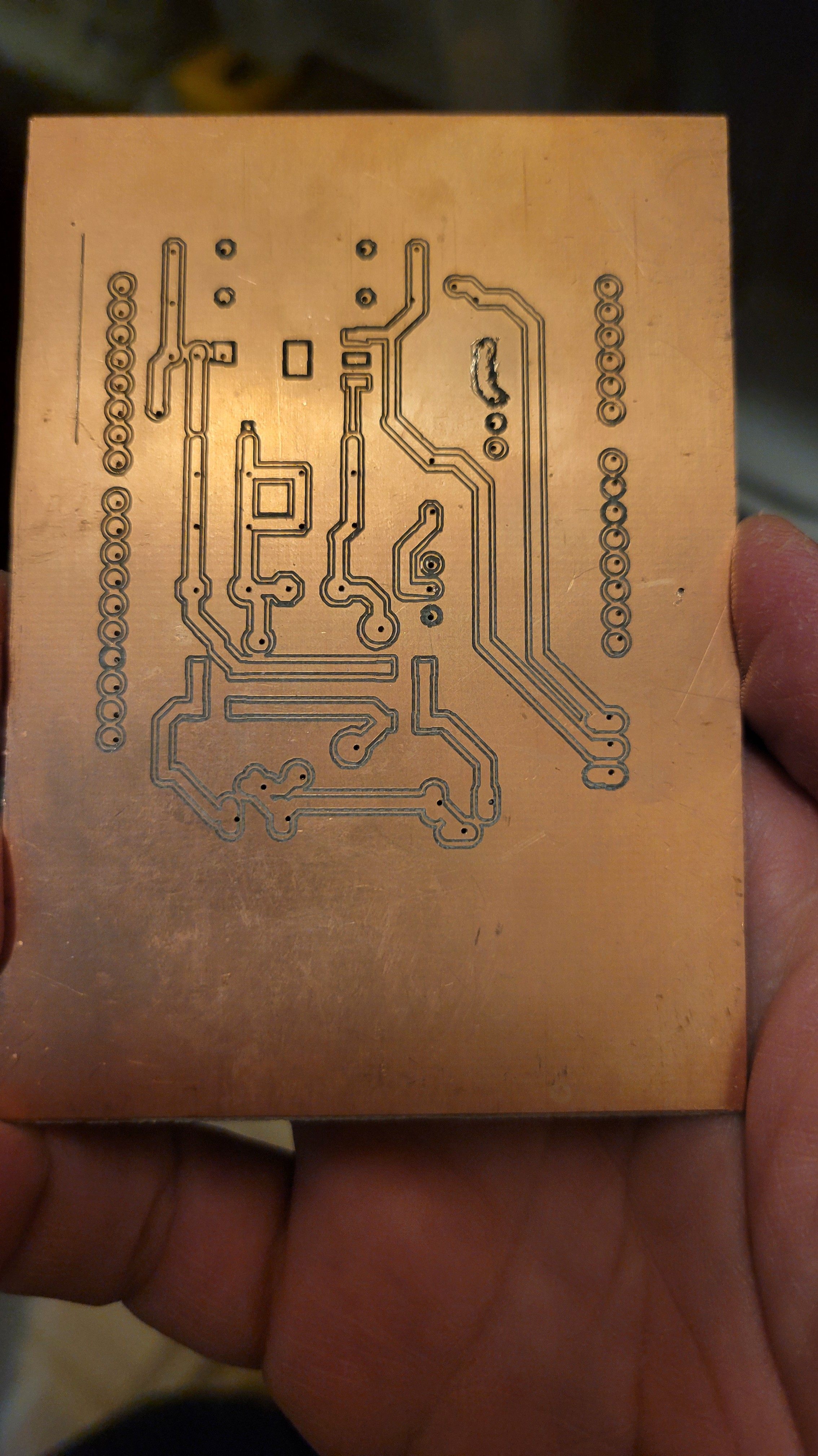
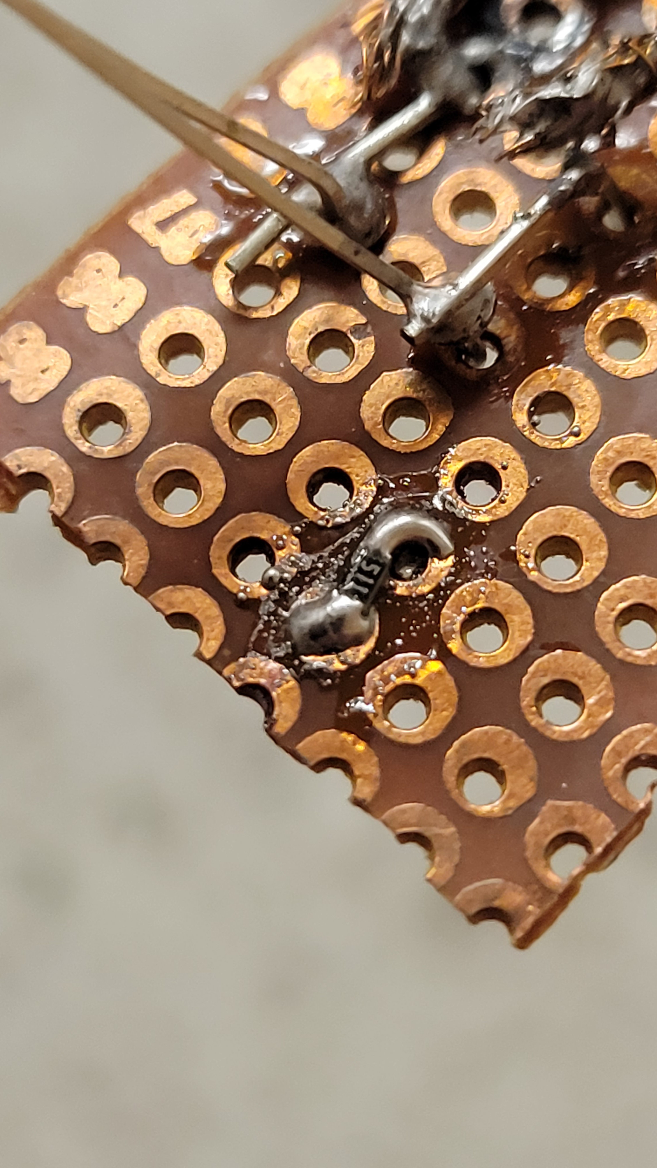
Luckily there are no components and I could carve away some PCB. Testing it I found that 3of4 pins are working (one is needs to re-solder but it's mild problem)
![]()
So it just works! I was surprised in a good way.
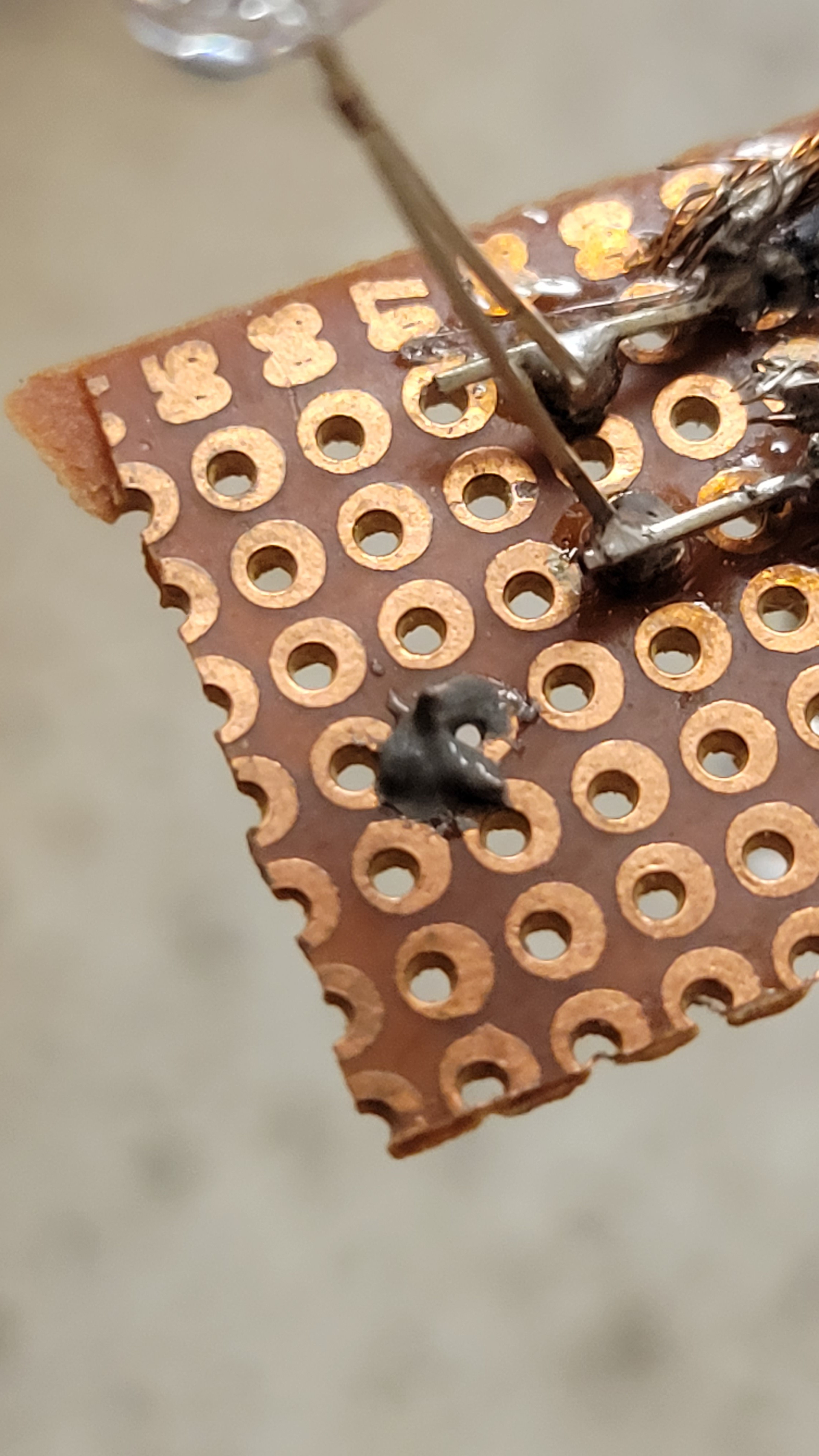
Gently I cut the wrong connector with Dremel.
![]()
But then I've discovered that my charge pump is not giving me negative voltage. I really wanted to avoid it...
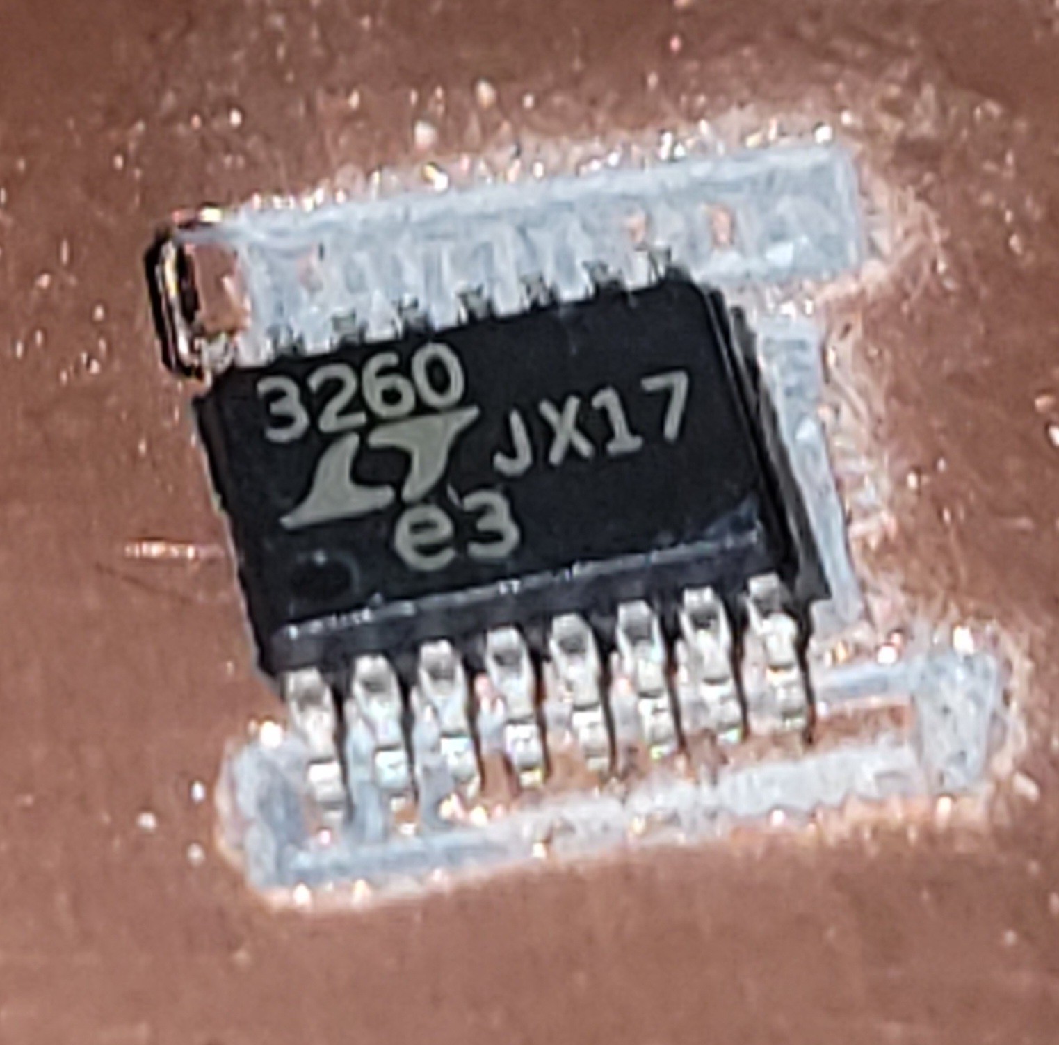
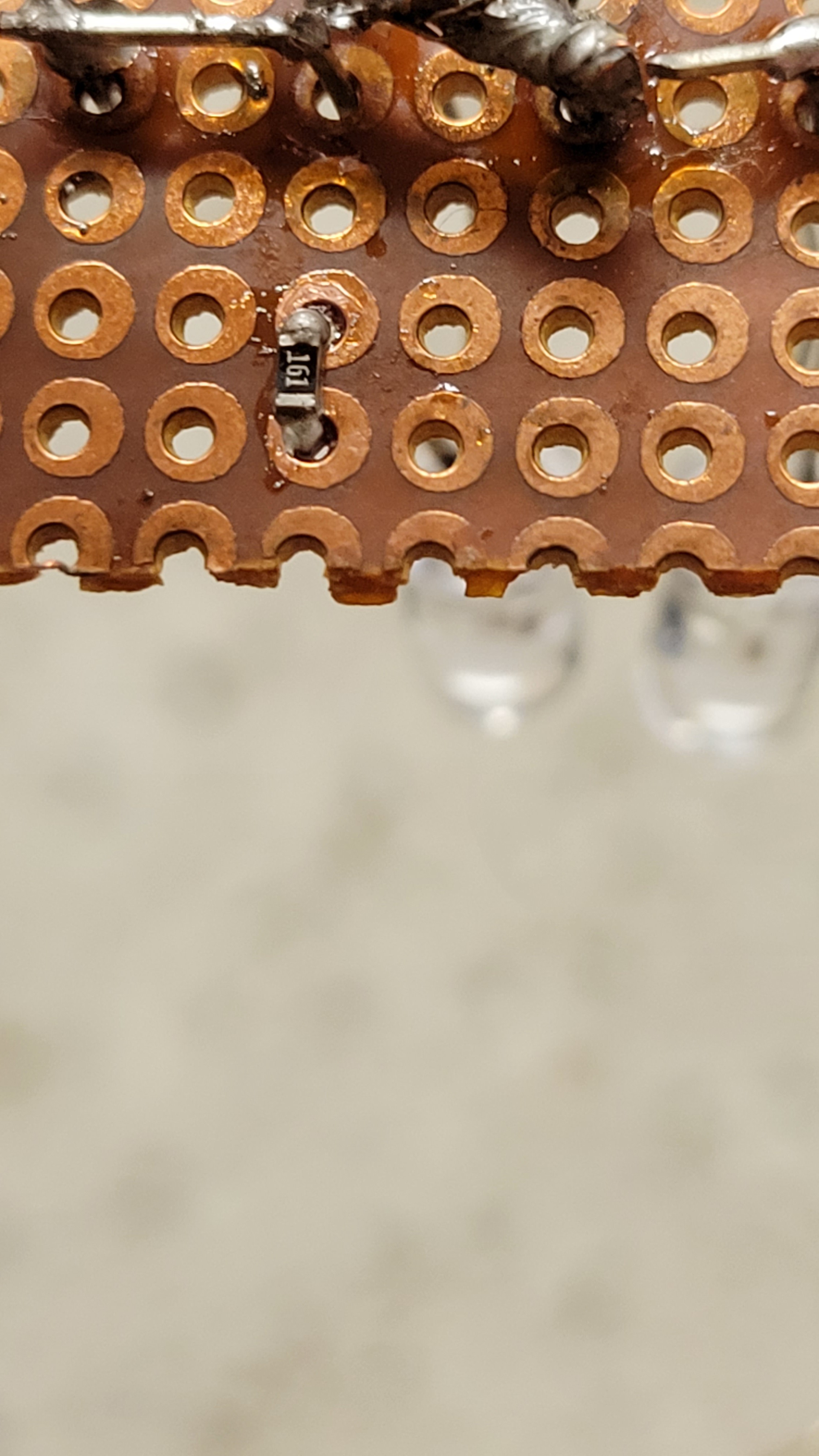
After re-soldering LTC3260(charge pump) it gave me negative rail but only 6 Volt. I thought charge pump could rise the voltage but from documentation it looks like it cannot go higher than input voltage. It's another fix I should do, nevertheless we can proceed and say we finished with this board for now
![]()
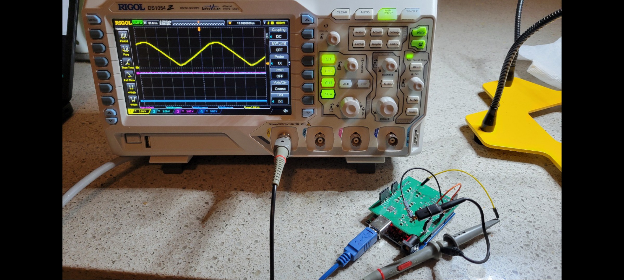
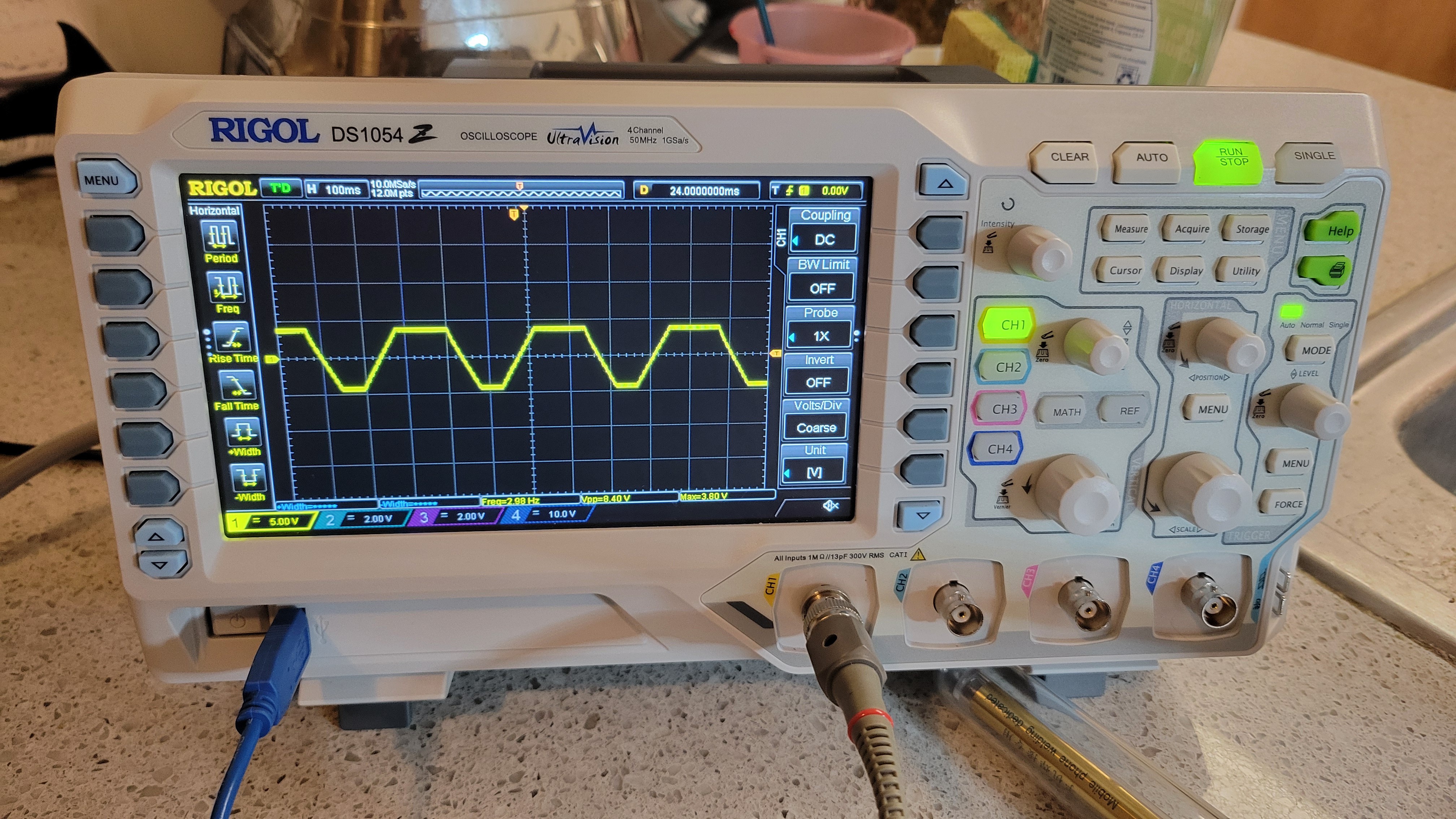
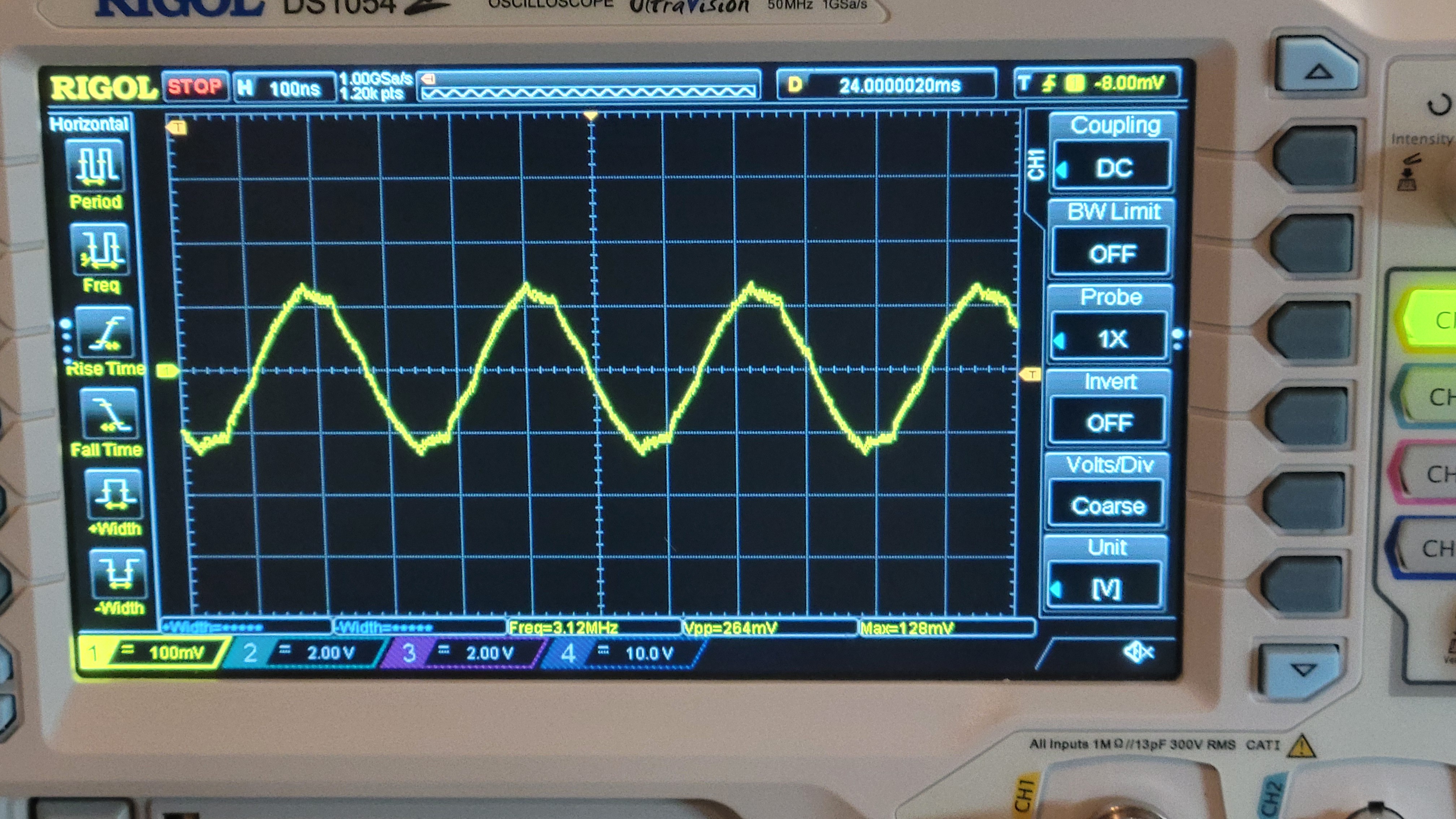
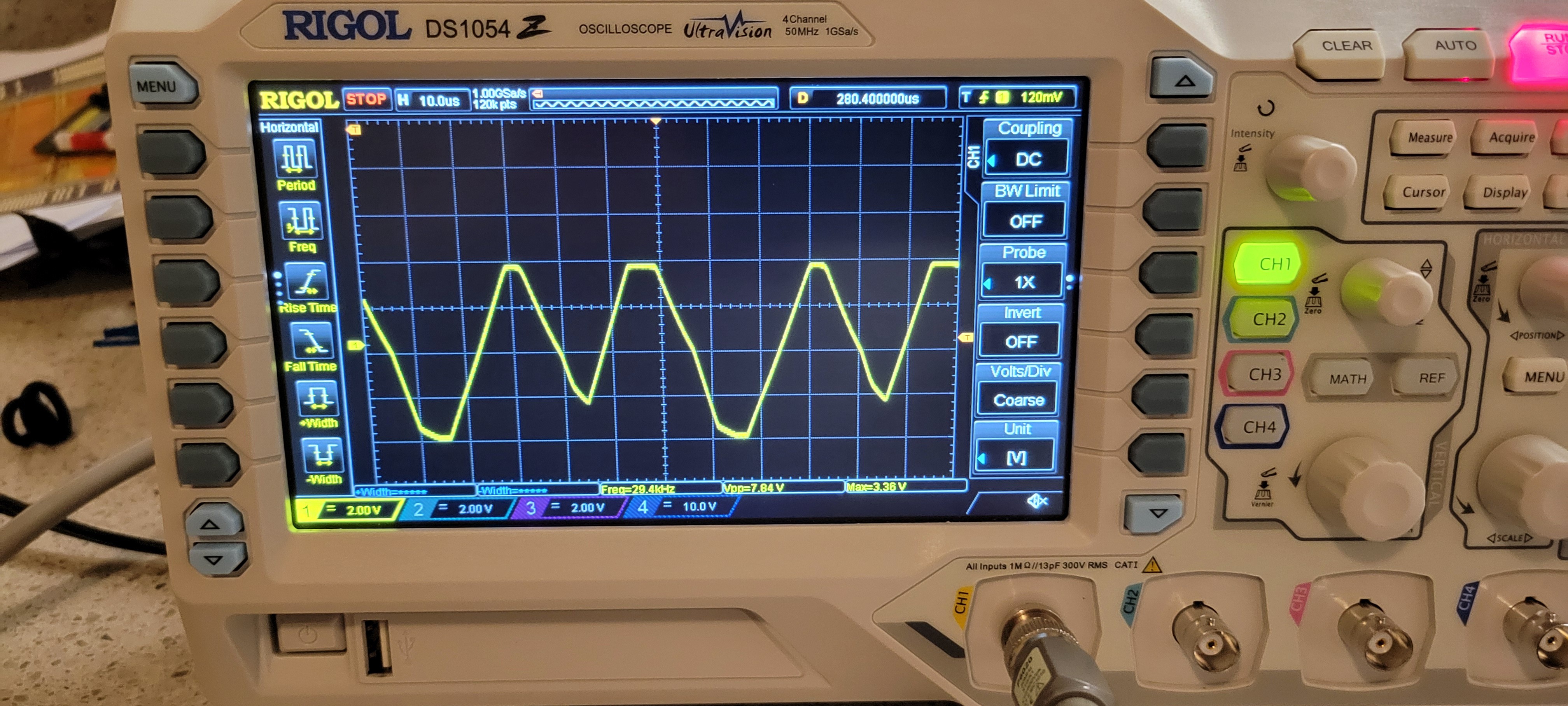
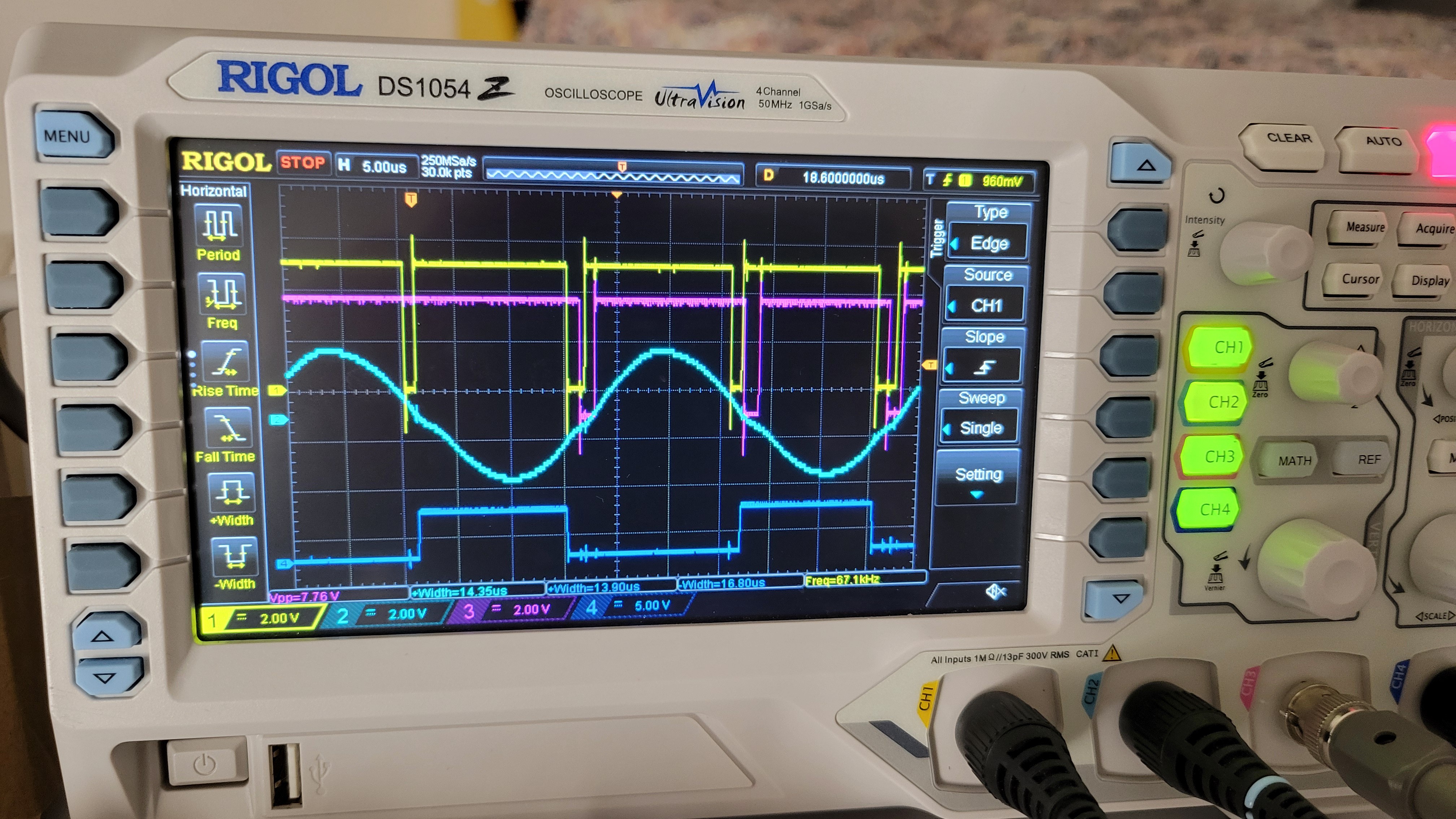
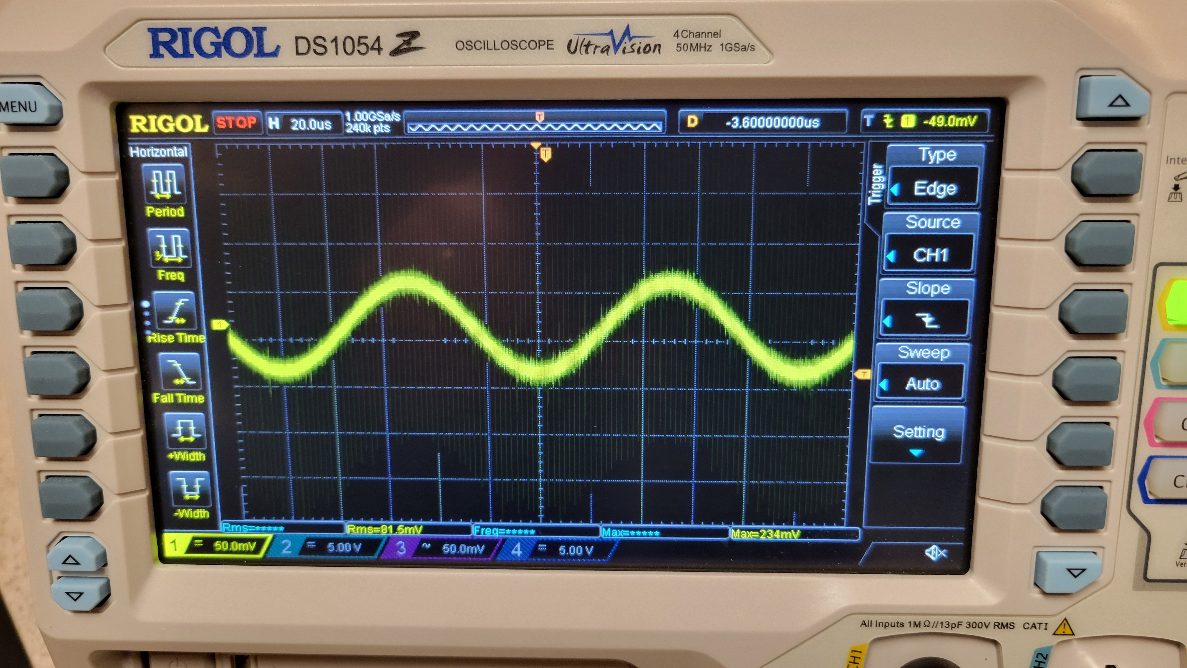
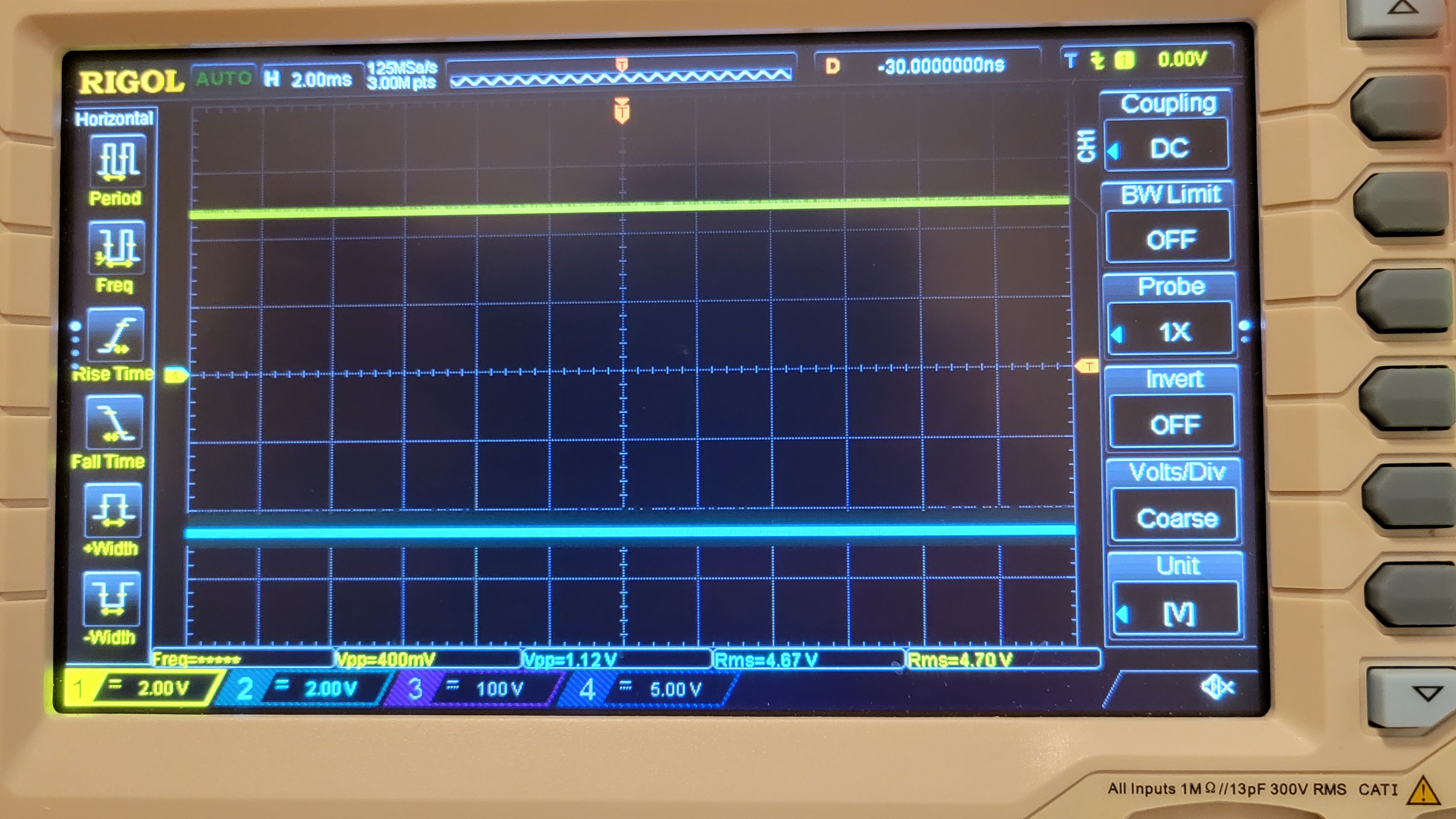
And the signal for four channels
![]()
It's upper and lower part truncated because of;324 opamp low voltage(of 12v instead of 30v). For now I can fix it programmatically by using only part if the full range.
It's good enough for now until I will apply all the fixes.
So... I have QFM module board, power supply board Peizzoelectric controller board. Now it's time for the last one... The input board (the one that generate signal for QFM module and reads QFM output)
Input board have mainly three parts. First is was connecting clock for AD9833(signal generator) Second connect AD9833 and be able to control it via Arduino. Third and last part is phase detector.
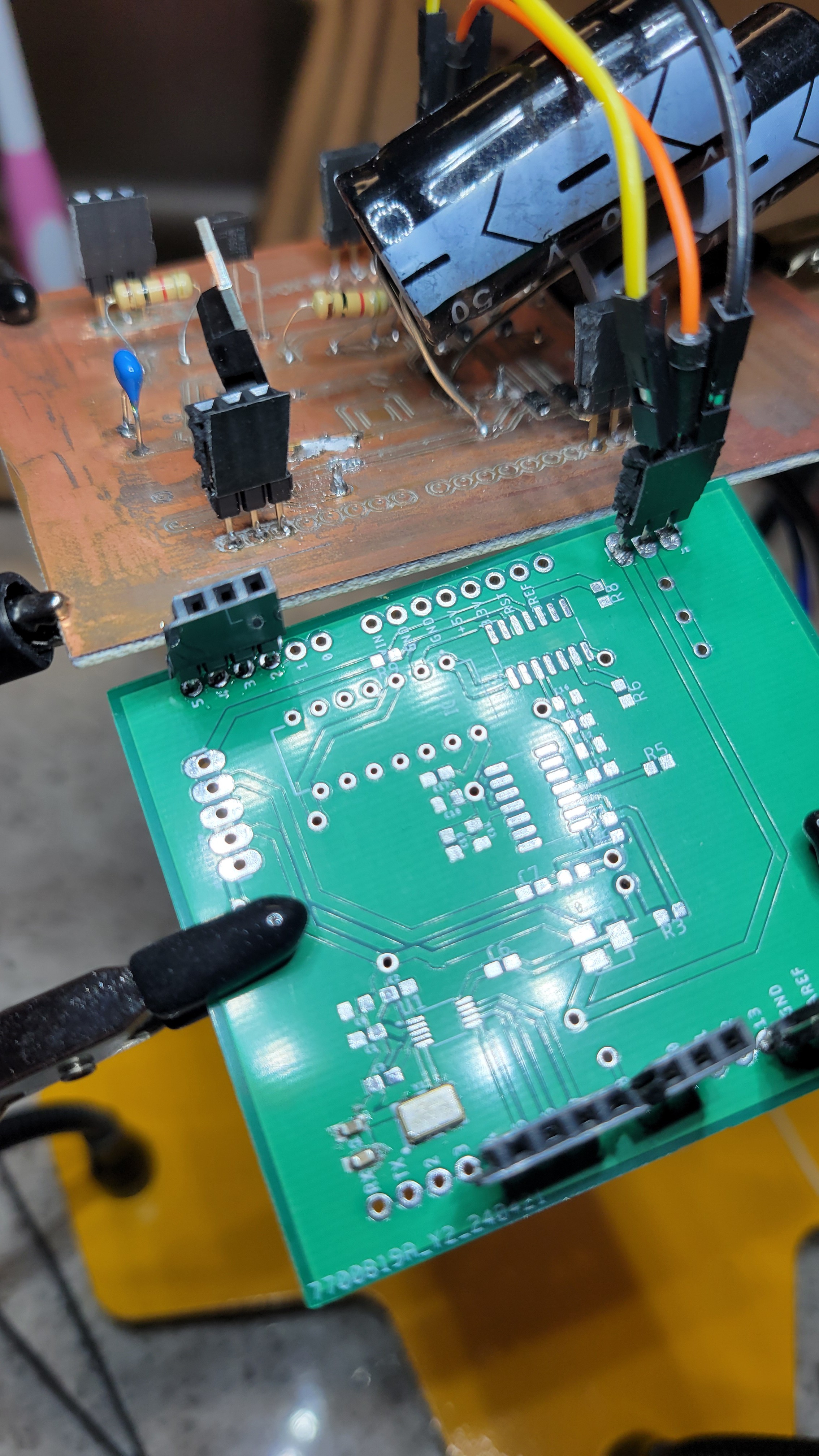
Here is the first part
![]()
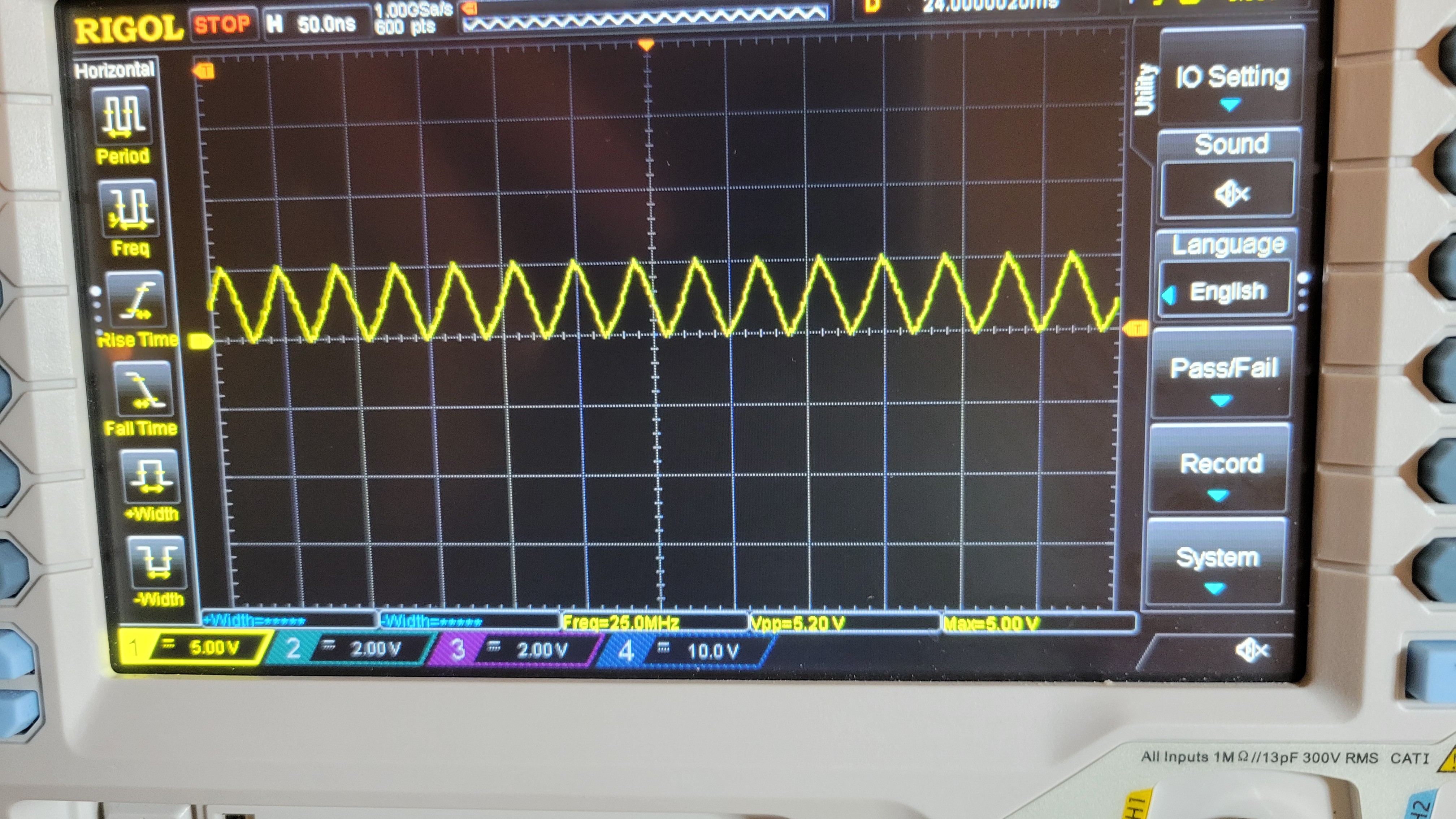
And generated clock signal
![]()
With stable 5v 25MHz signal. Usually clocks are very sensitive to many factors so I was happy to see it's working without to much hassle.
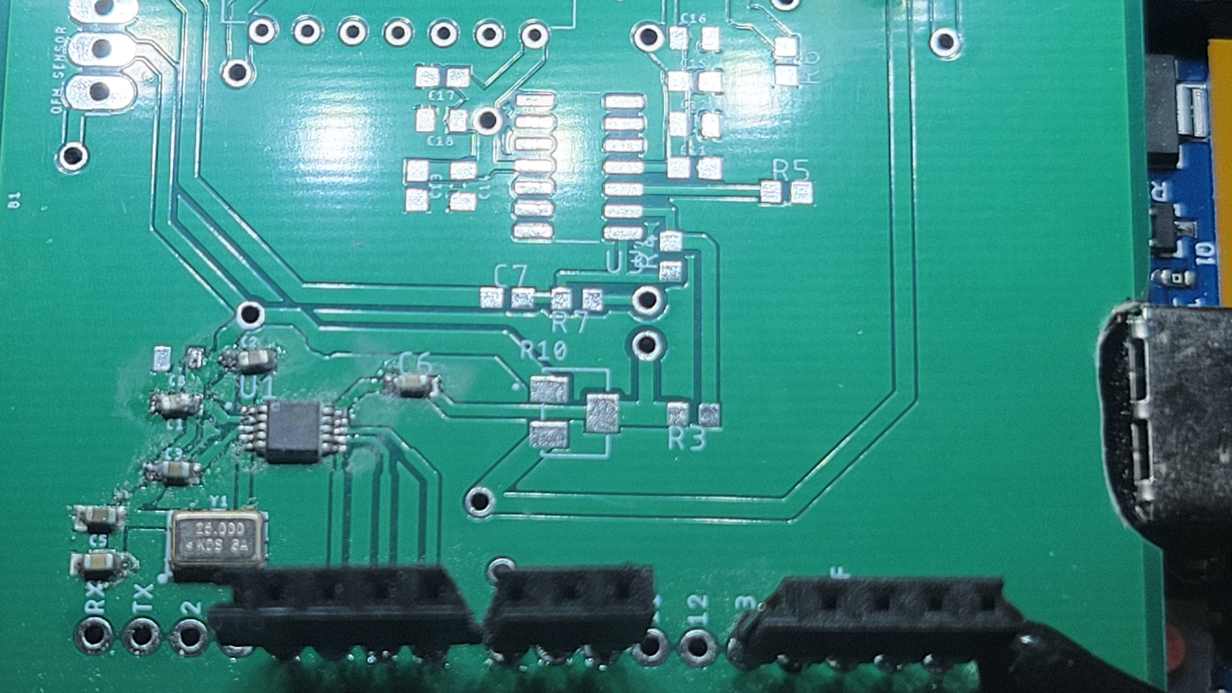
Added AD9833
![]()
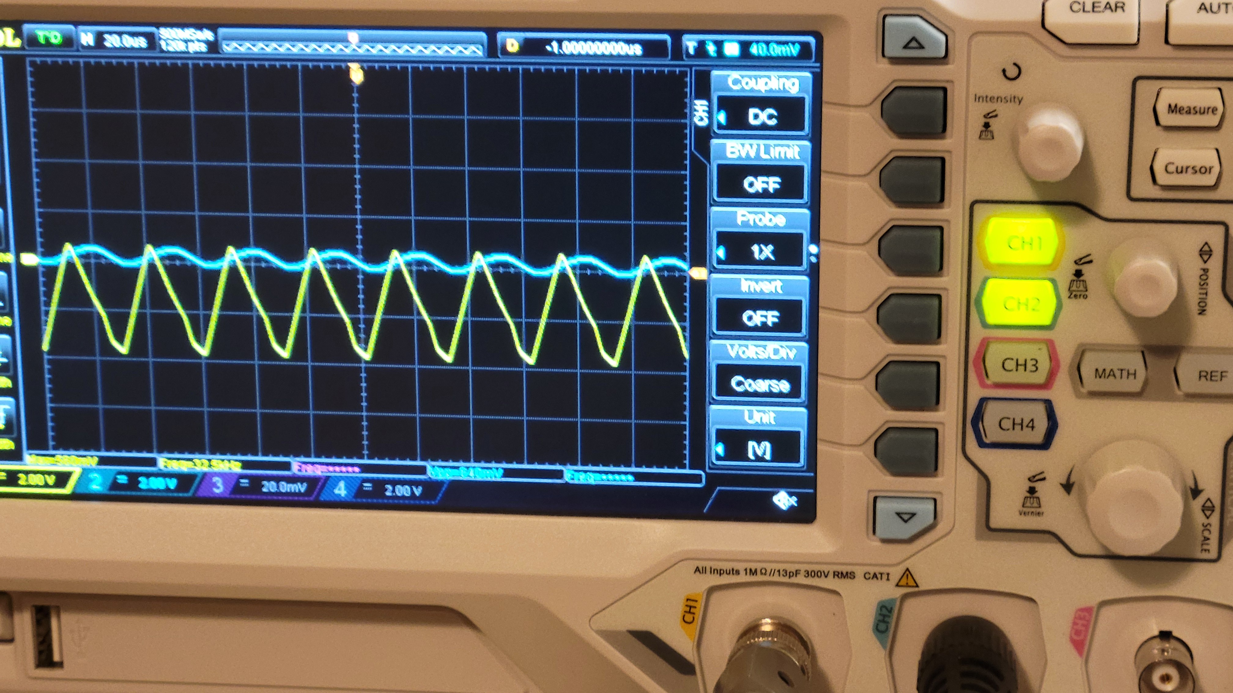
The signal on the other hand looks with some jitter more over the frequency is wrong(should be 32KHz), at least we got signal 😕
![]()
After short debug it was just a software bug where pin numbers were swapped. Phew... Now the fixed version is much better both stable and nice signal (and correct frequency)
![]()
Now I started populating the resistors and it looks like I totally forgot the circuit although it was the last one. So here is the schematic with resistor values.
![]()
Time to solder!!!
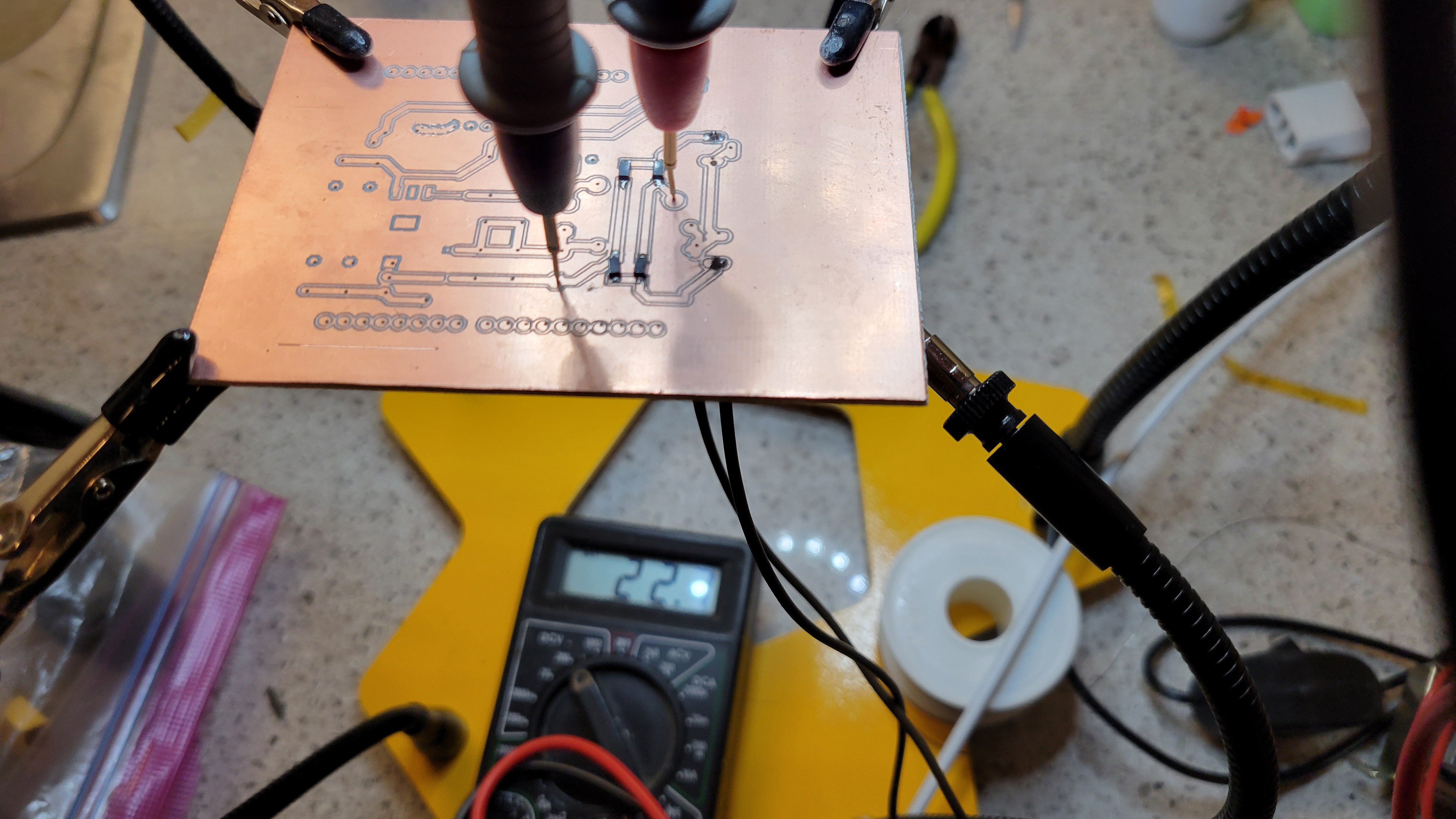
Once I've connected both power supply and usb, things got out of hand.
![]()
So now I connect usb only when the main power supply is disconnected and via versa.
Another problem was 7805 d im my case giving only 0.1A I thought it is 1.5A. The reason for the confusion, in my case, is that SMD was 78l05 and didn't give enough attention.
OK, designing a new power supply board
![]()
Meanwhile, I got unforseen problems with setting up my board for some reason there is no communication between AD9833 and Arduino. Another problem is that output of op-amp is heavily overdriven.
The first problem can be solved by connecting +5v of Arduino to +5v of power supply. I am not happy from this approach but it's working for now. (The strange thing is that Arduino communication provides 5v which makes both 25MHz clock and AD9833 run, with wrong parameters/frequency).
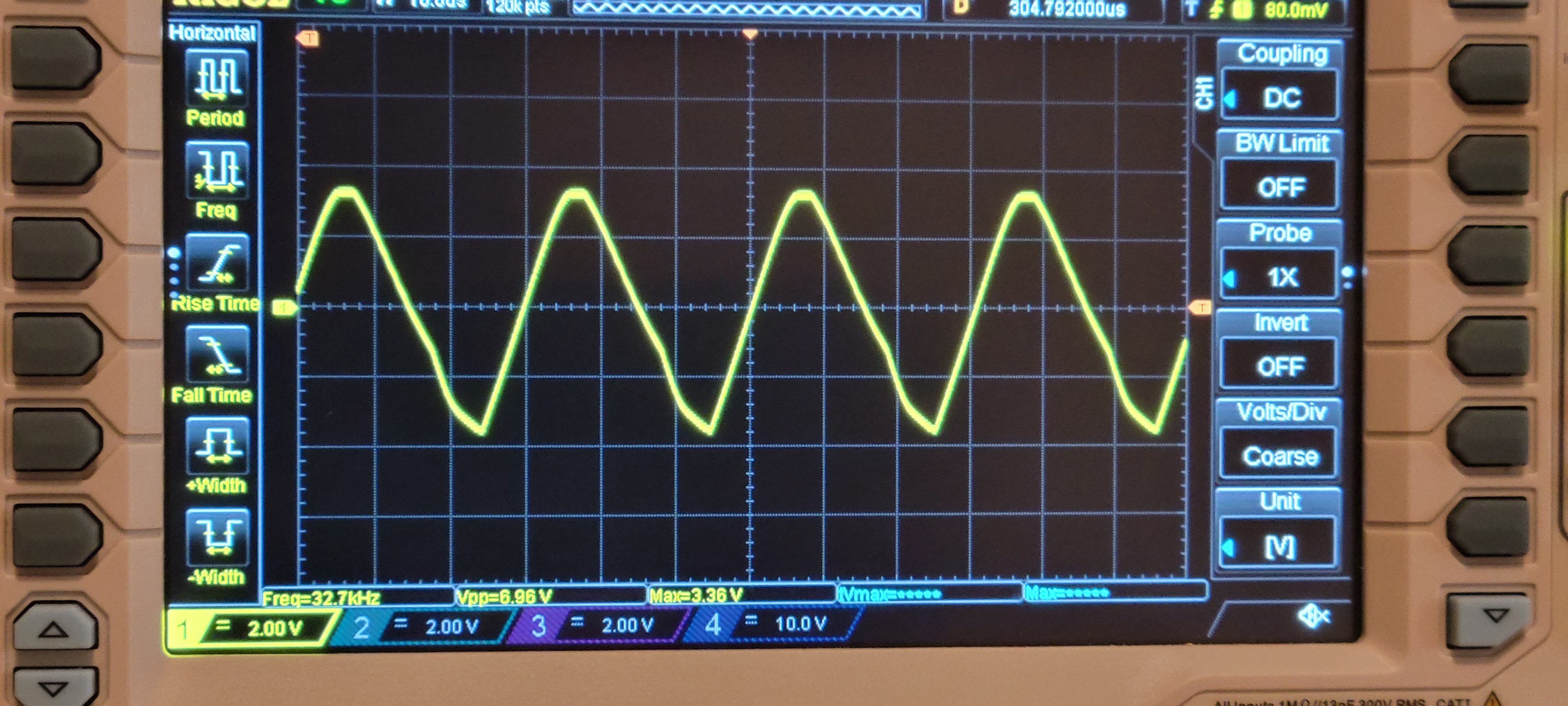
Second problem should be solved by changing resistance values of op-amp. Otherwise it looks like:
![]()
Although it's 32.7KHz it very shaky. I don't know why I choose those values (2KOhm and 100KOhm). Probably some copy mistake. I will try 7.5KOhm and 100KOhm.
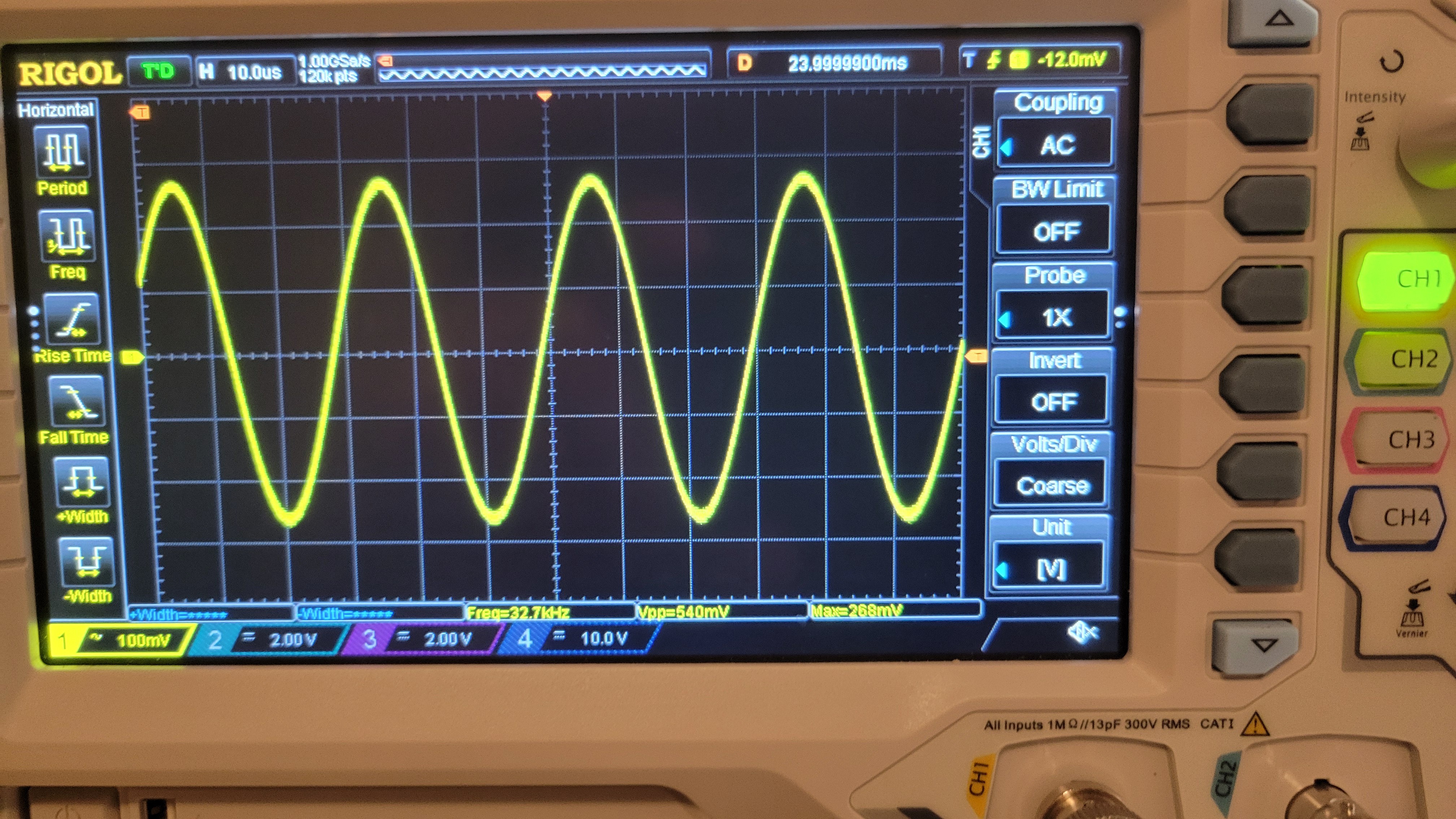
Now it looks much better, with the right frequency and much more stable
![]()
This is great but I still have a problem to connect Arduino to the board I've added 100Ohm resistors This partialy solved the problem. Now it reads only on beginning 🙀
It's ironic that the only 'easy' part in the system gives me the headache. No matter what Arduino UNO doesn't want to communicate with AD9833, only in the beginning. So strange...
It was totally ok with Arduino Nano and AD9833 with factory built board. Let's go back and see what is working with what.
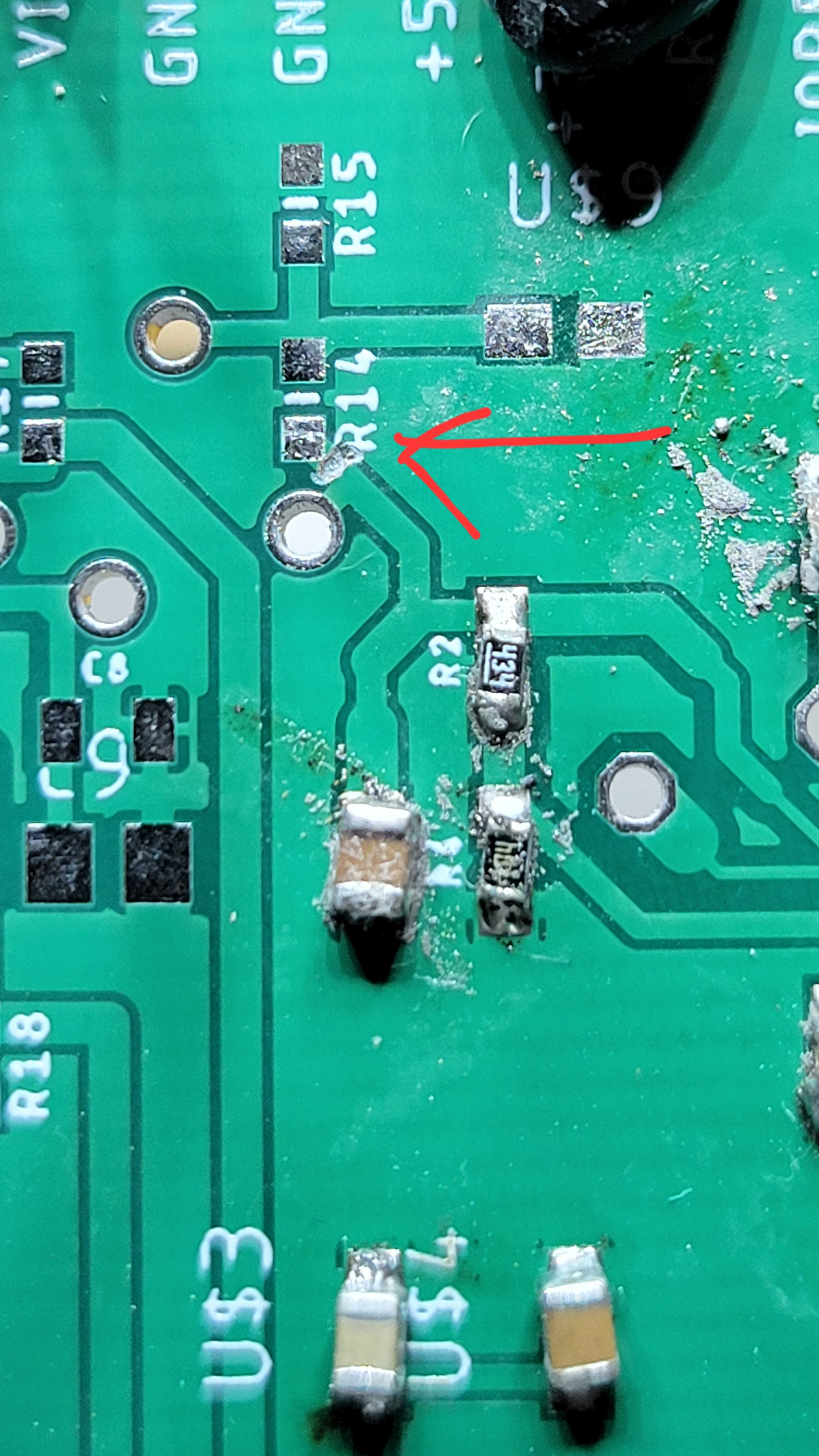
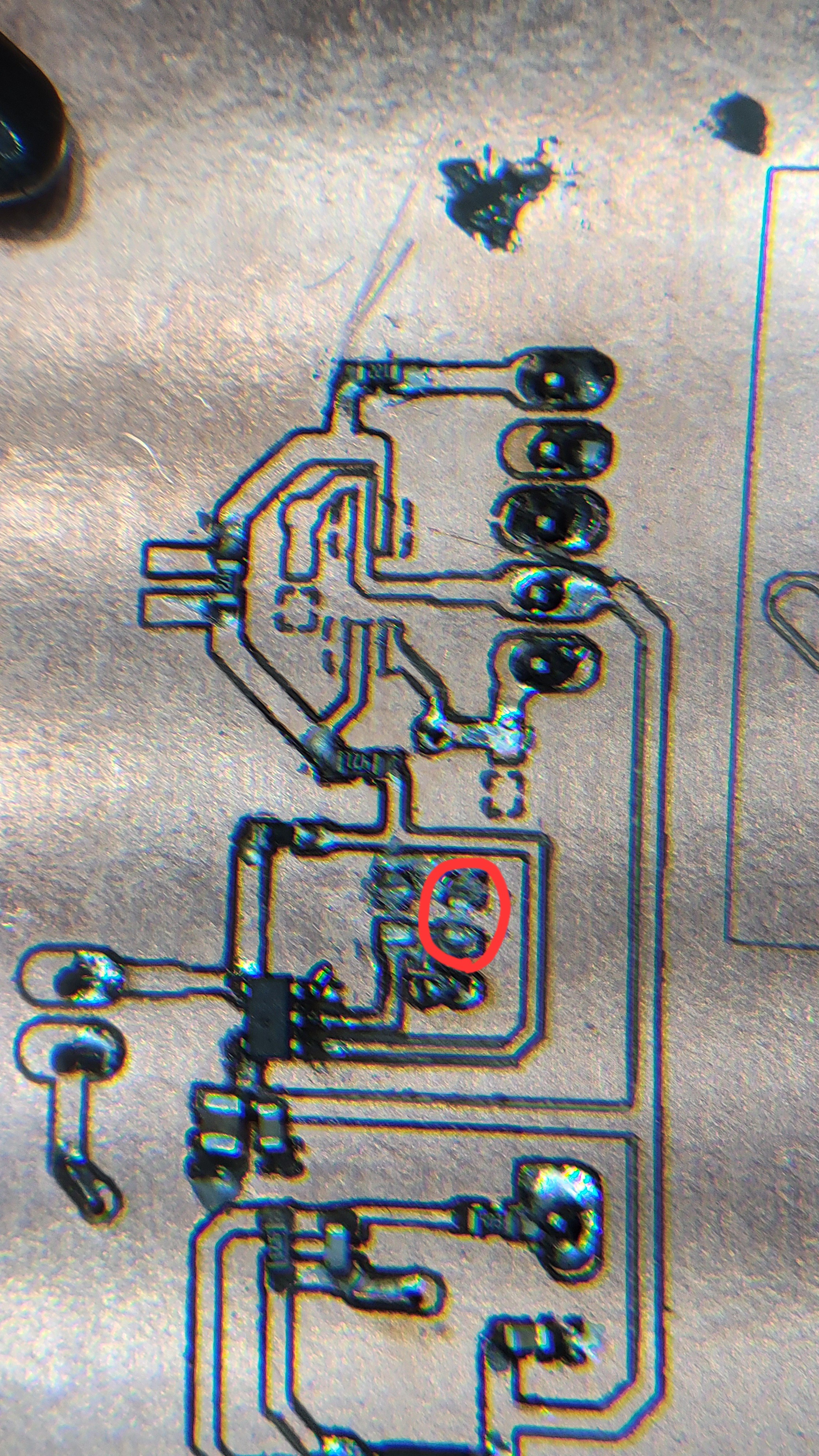
After checking with factory made AD9833 PCB. Arduino is working as expected so it's not Arduino nor power supply issue. After going through schematic I found that one of the terminals, CAP/2.5 should connected to ground instead of Vcc. This solved the issue and now I can control AD9833
And the output of op-amp is nice and stable 7v (almost) sine wave.
![]()
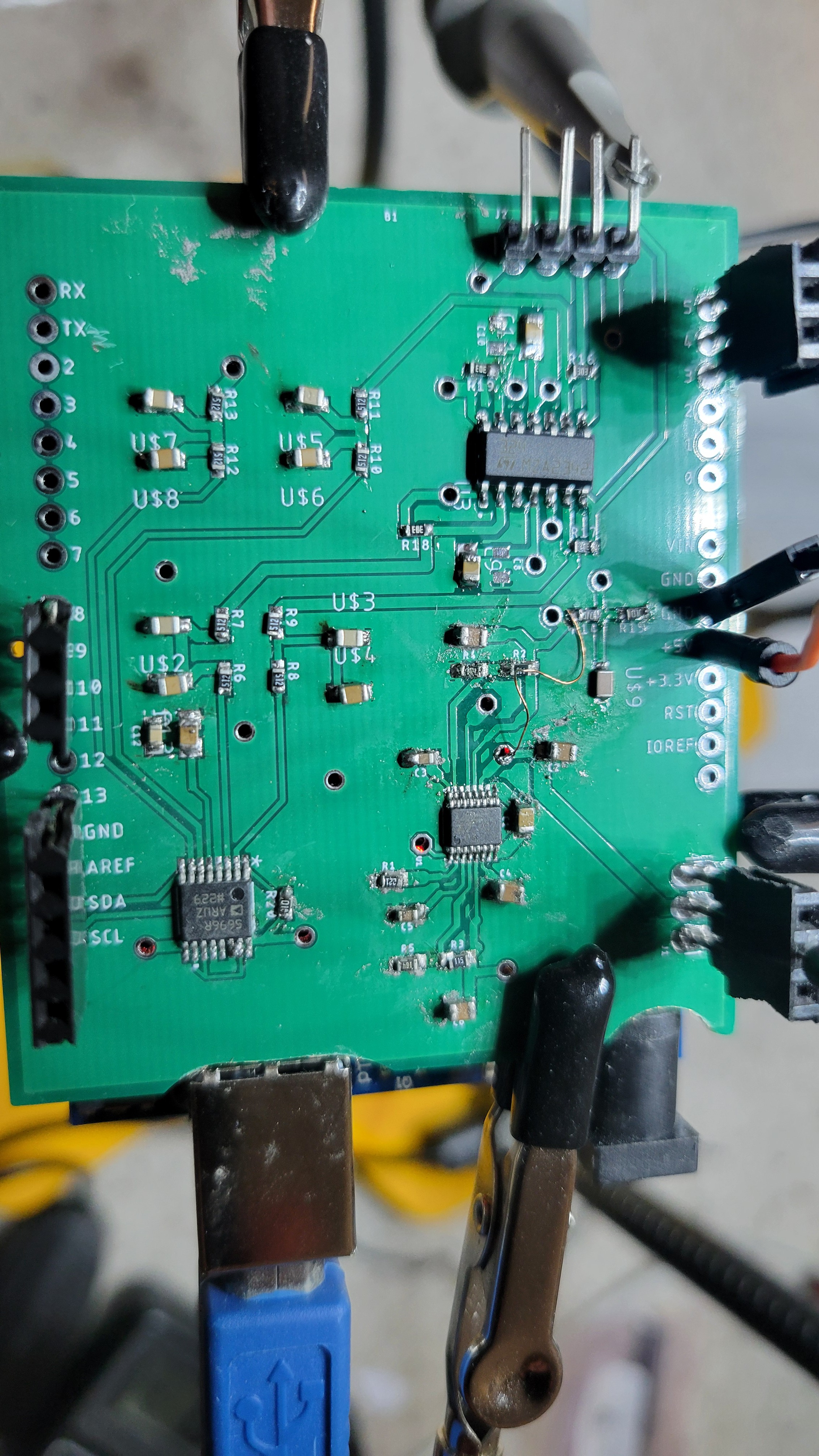
Now, added comparator just to find that I forgot pull up resistors. Another last minute change.
Now seems working...
![]()
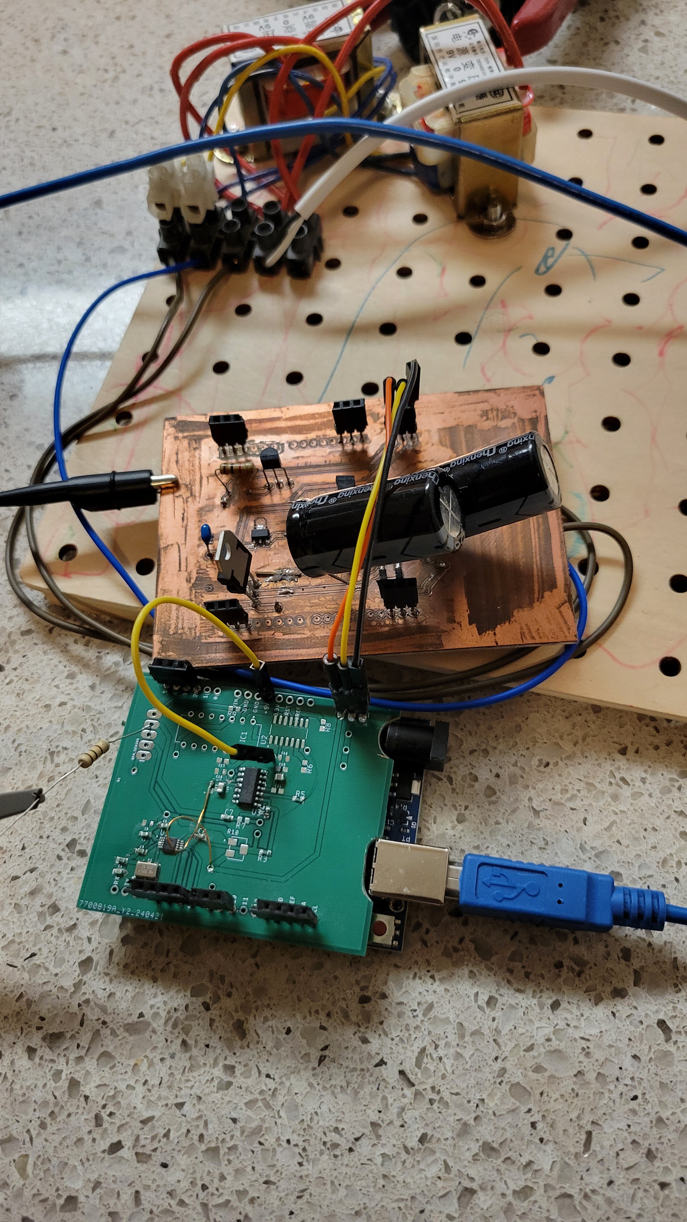
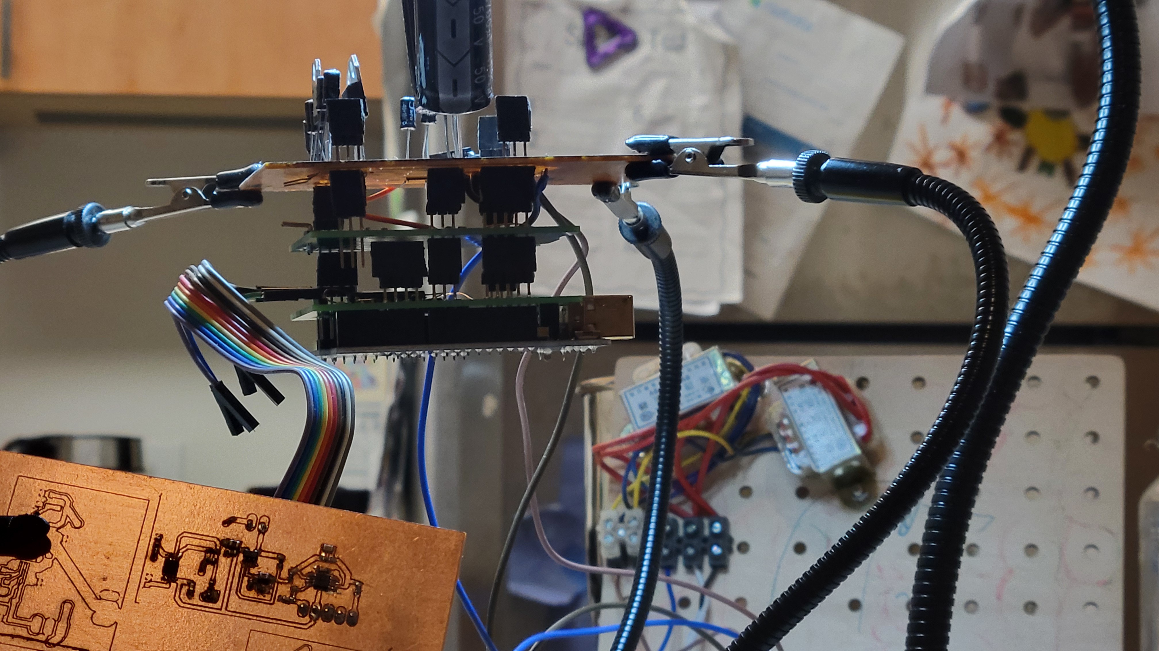
In the end all the board got stacked and looks like
![]()
Next step is to connect everything together and make first experiment.
-
Sensor board
02/02/2024 at 21:56 • 0 commentsUntil now we made the QFM (quartz fork) module and we used signal generator to create a sine waveform with specific frequency and measure the output using scope.
Now we want to do it programatically. We would like to have a device that will gnenerate frequency as a command from Arduino board and meassure the output using Arduino.
![]()
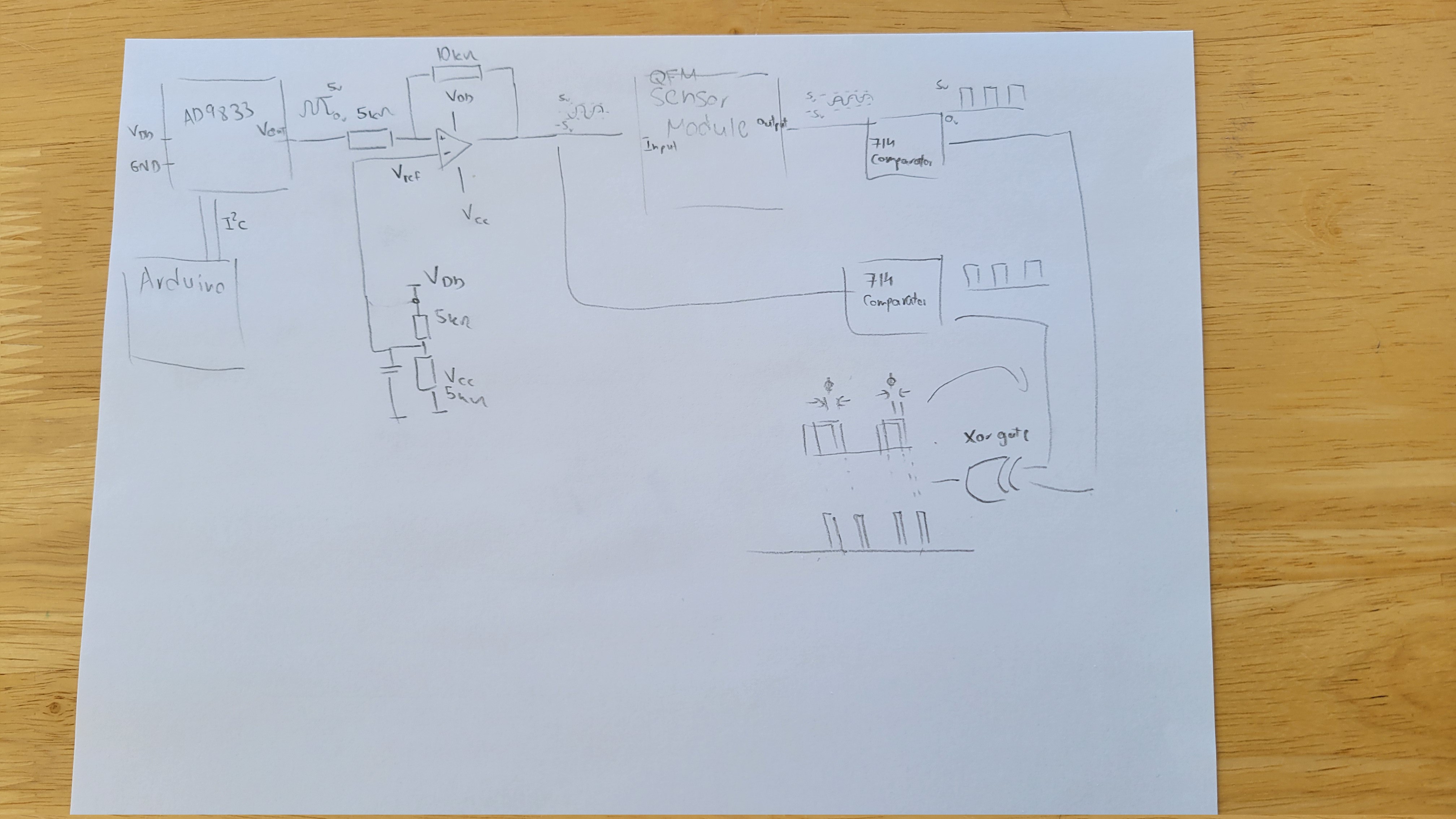
To create a signal we will use AD9833 signal generator board. (For now as a external PCB board with few capacitors and crystal clock). AD9833 can output frequency with 0.1Hz precision. Arduino can provide I2C that will set AD9833 to the desired frequency. For output we wil look for zero phase as this is less error prone (at least it's looks for me now).
The next step would be to add xor and integrator to find the phase difference.
For now we can see it how it changes.
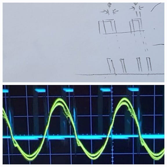
Now, I've added two comarators and XOR gate and got nice two peaks for each half cycle as expected.
![]()
Now we get digital output of the peaks. Since output is digital we can simply sum the time output is high relative to low. The frequency where it's most low is the main frequency.
The last part would be a converter of AD9833 which output is 5-0v to voltage needed by QFM module which is 5-(-5)v.
-----+-------------+------------+--------
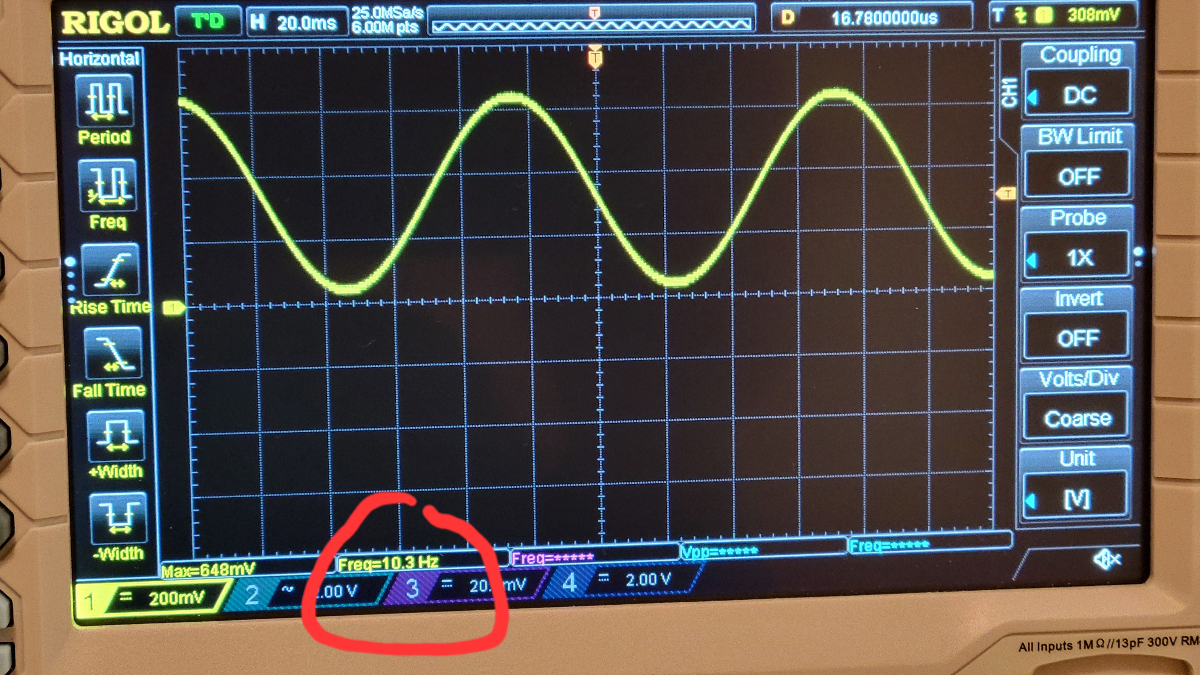
Ok, got AD9833 connected and running. The amazing thing I didn't know previously is that it can get float numbers which means we can set frequency of sub Hertz. For example here I've set 10.3Hz
![]()
The last part will the LM324 op amp to convert 0.6v of AD9833 to 5-(-5) volts swing that will be input to QFM.
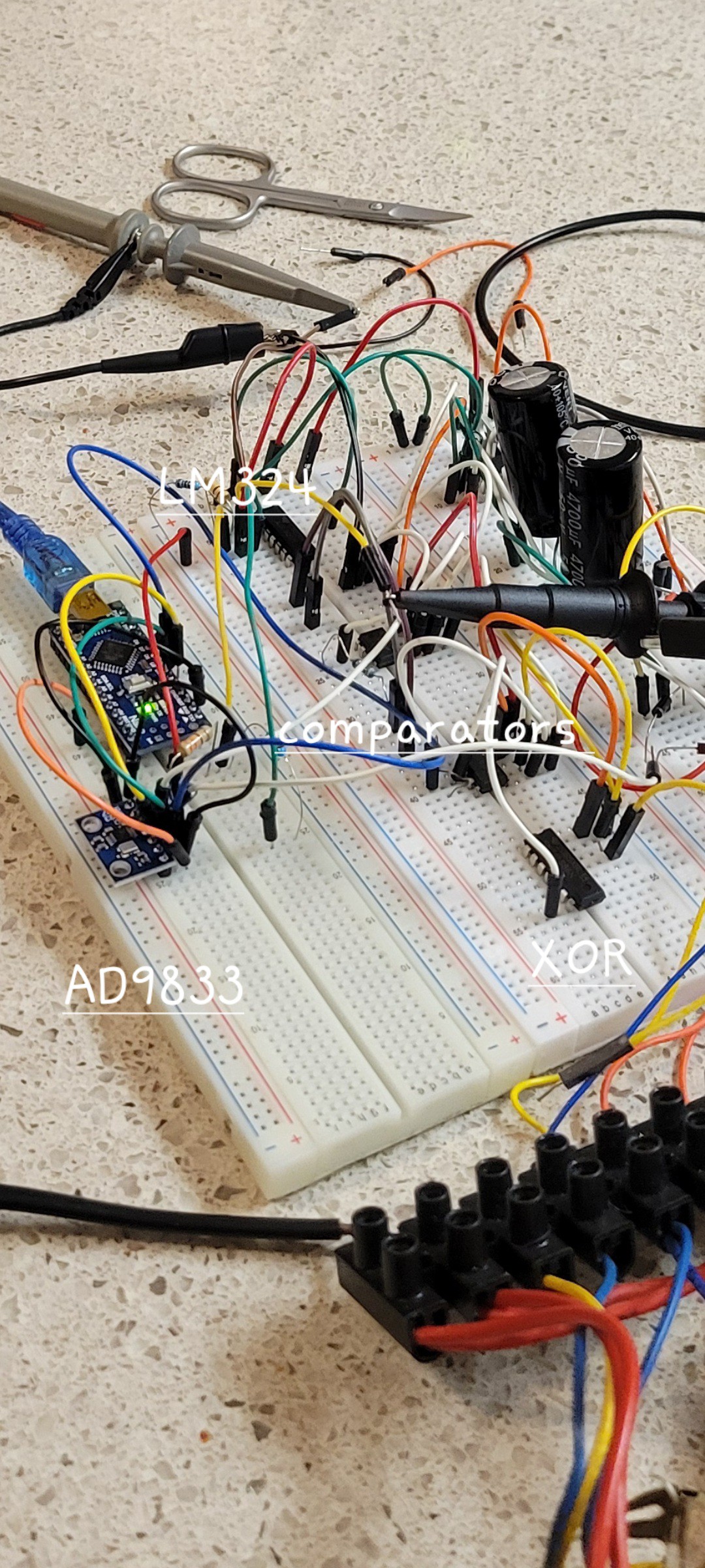
Ok, got all components together working...
![]()
The output is bit warped but I think good enough to me. (It should be sine but it looks like triangle)
![]()
That's all for the electronic part.
Next stage would be to put them on PCBs. Working on breadboard is not convenient
After adding some twicks, I got this out.
When signal alighn (no phase difference) you got almost zero
![]()
Now, same setup, different frequency and you got
![]()
------------- UPDATE -----------------
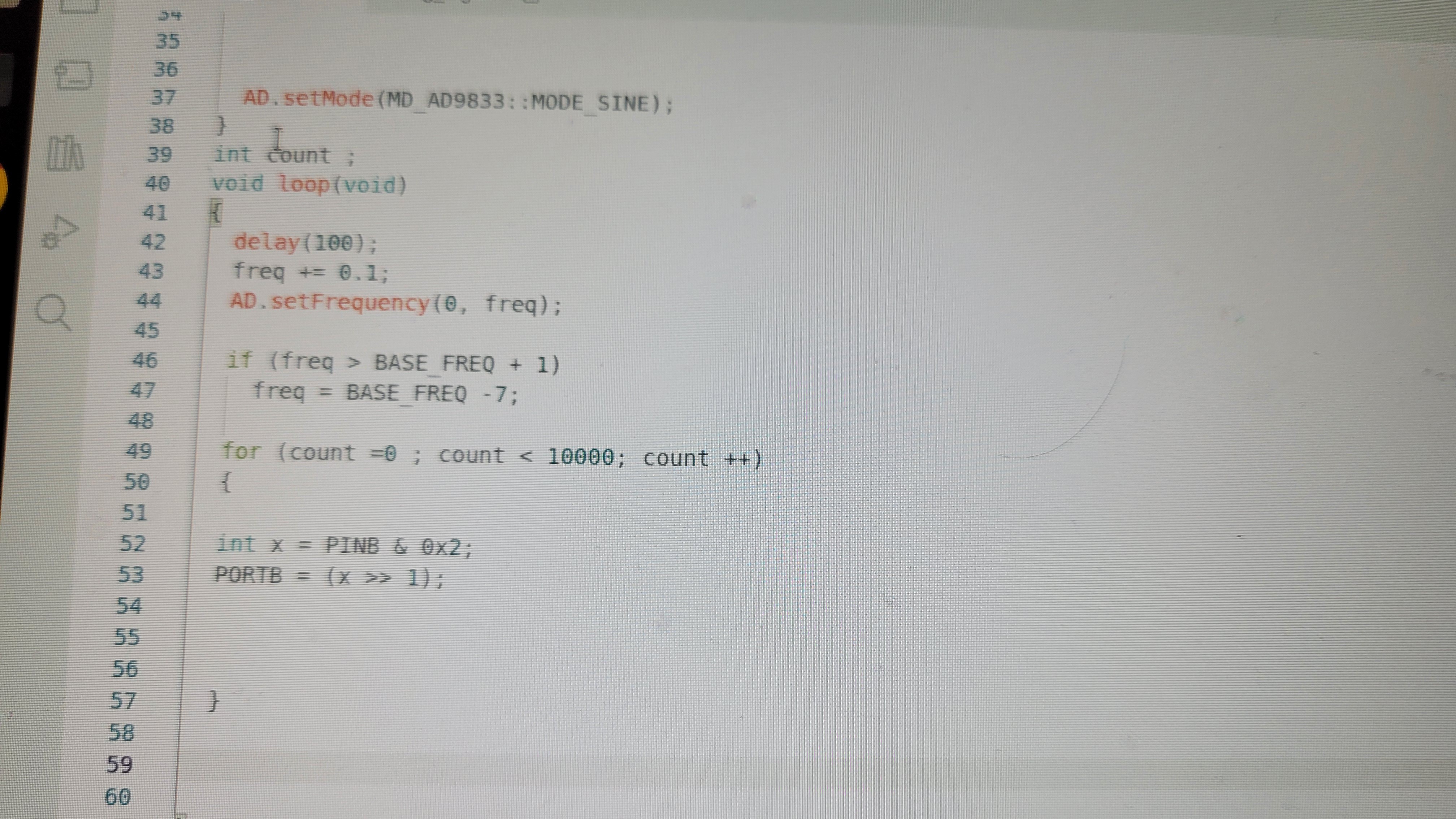
I felt I had to check all the way from clock generator to Arduino. Especially the connection between XOR gate to Arduino. So I've made simple Arduino program that simulates it's input. It's output high when input is high and low in the other case. The result was surprising, simpleReadPin and writePin was too slow. With such low resolution of 5 micro seconds Arduino could not differentiate between match and mismatch. For me it was OMG moment since changing Arduino to FPGA means serious delay. Luckily I know it's only implementation issue. Arduino runs on 16MHz clock and output read/write are two clocks. Which leaves enough time to be sub micro second measurement.
So going to assembly level with PORTB and PINB commands
![]()
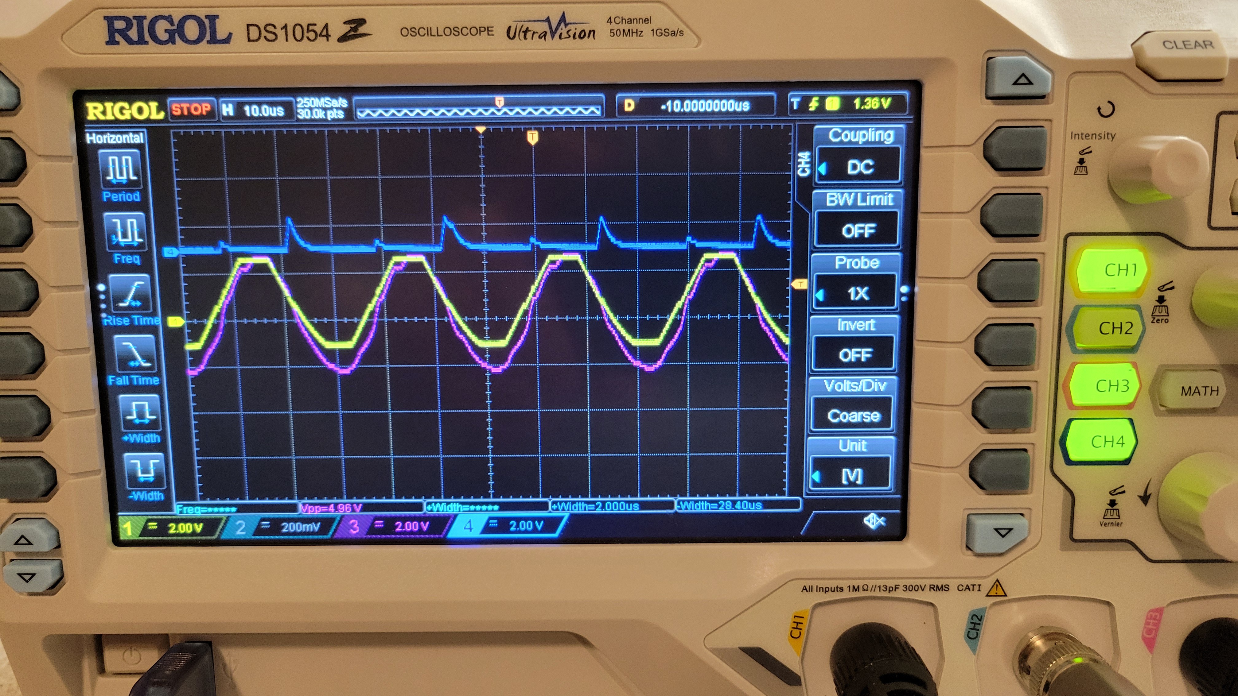
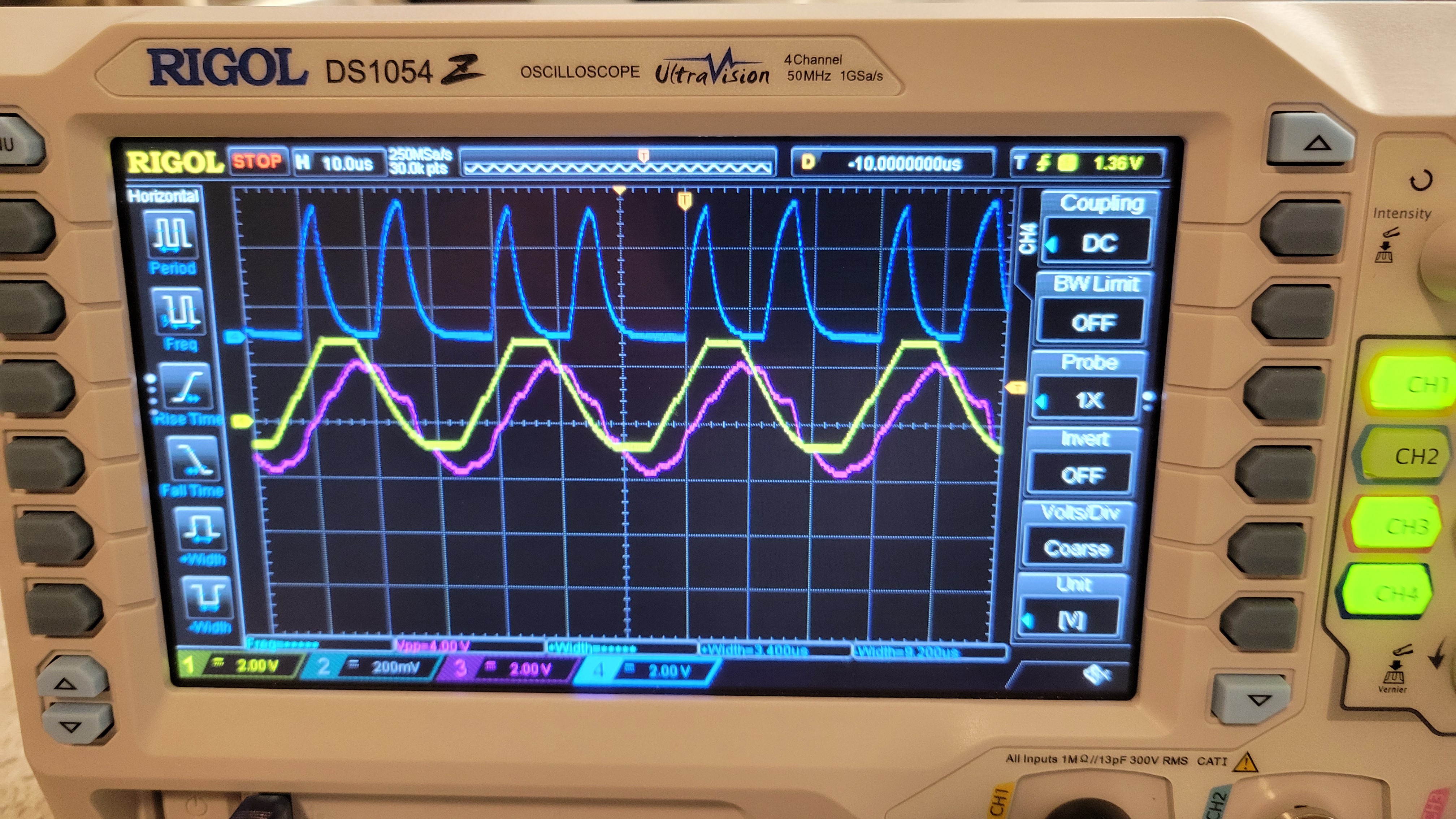
Gives us nice results of
![]()
The yellow is XOR gate output and pink one is Arduino output. We can see that Arduino is following most of the changes. (Actually the real measurements would be faster since instead of PORTB command it, of two cycles, it will be simple add command of one cycle.) Anyways, it's good enough and we can continue to building PCBs reassured that electronic part is working and communicating with Arduino level correctly.
-
Soldering SMD - take 2
12/24/2023 at 17:01 • 0 commentsThis is a the point where I continue the 'Soldering SMD'. Last time I had to go back and fix the double rail power supply problem. Now it fixed and we may continue. First lets check the attenuator
![]()
Looks good we got about 1Vpp.
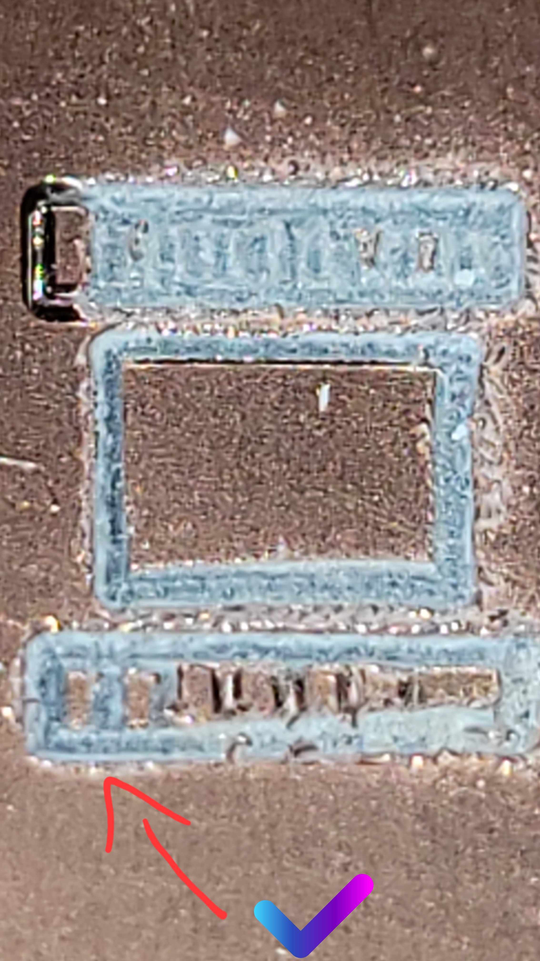
I found something strange or bug in the design the guarding ring is not coated so terminals of quartz fork may touch it.
![]()
Thus may lead to short circuiting. Hmmm...
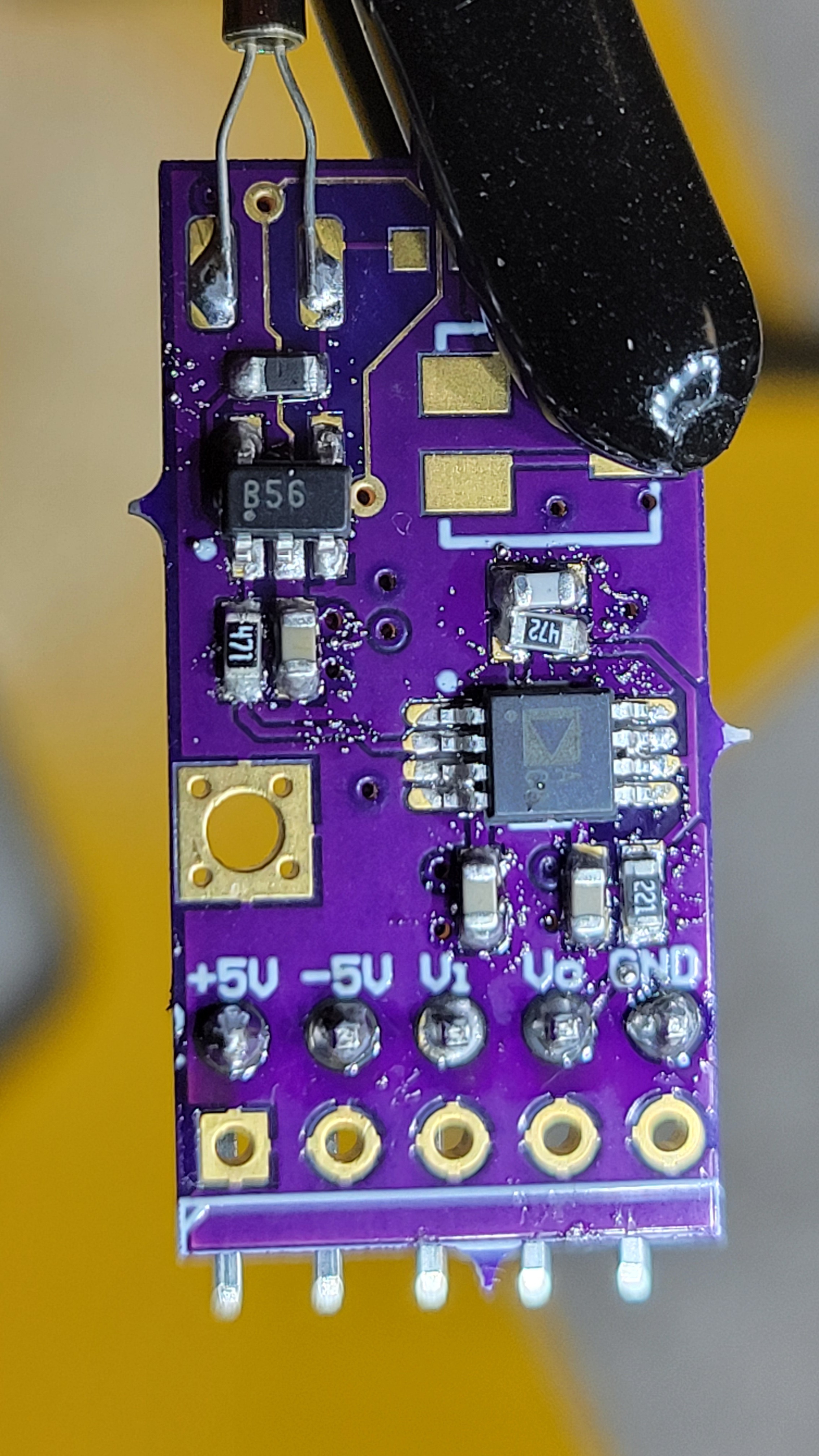
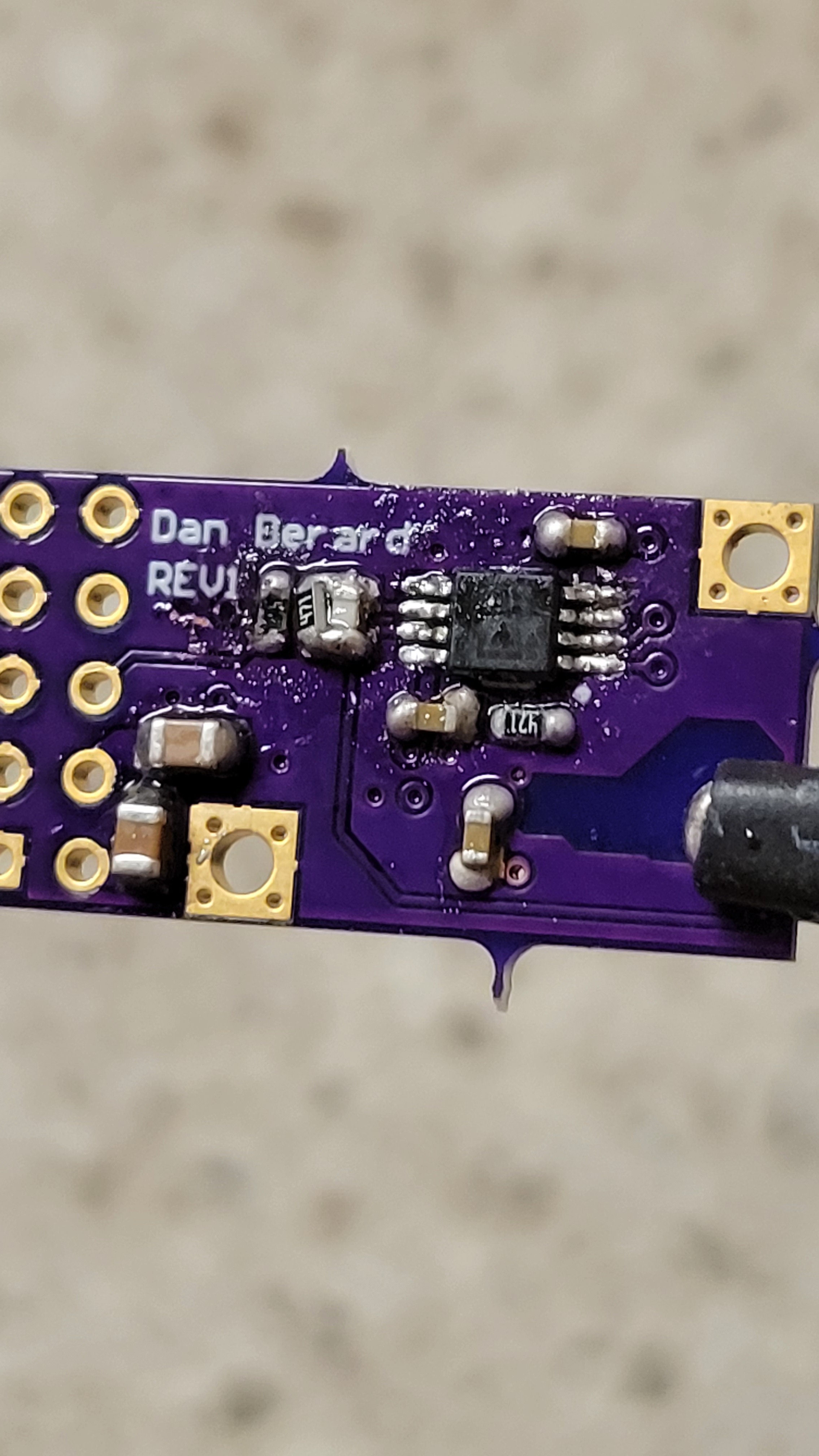
Now lets add all other components like OPA656 and another opamp.
![]()
Had some problem of putting to much soldering paste and all pins was glued together. But some playing around solved the problem.
Let's plug it in.... I will continue tomorrow it's getting too late...
The test was not successful, once I connected everything I got only noise. Since I don't have too much testing point I tested the output of attenuator. I was surprised to get there no signal. After while, I checked the power lines no power! What ?! Once disconnected power was back. The problem is I got shirt circuit somewhere. Found some problems in my soldering but still got no output. Checked attenuator output, still none. It *was* working before, how we went back?
Now I don't know what to do. Should I try to debug while I don't have accurate board design. (The one I got once I bought the board is blurry) or should I design one myself?
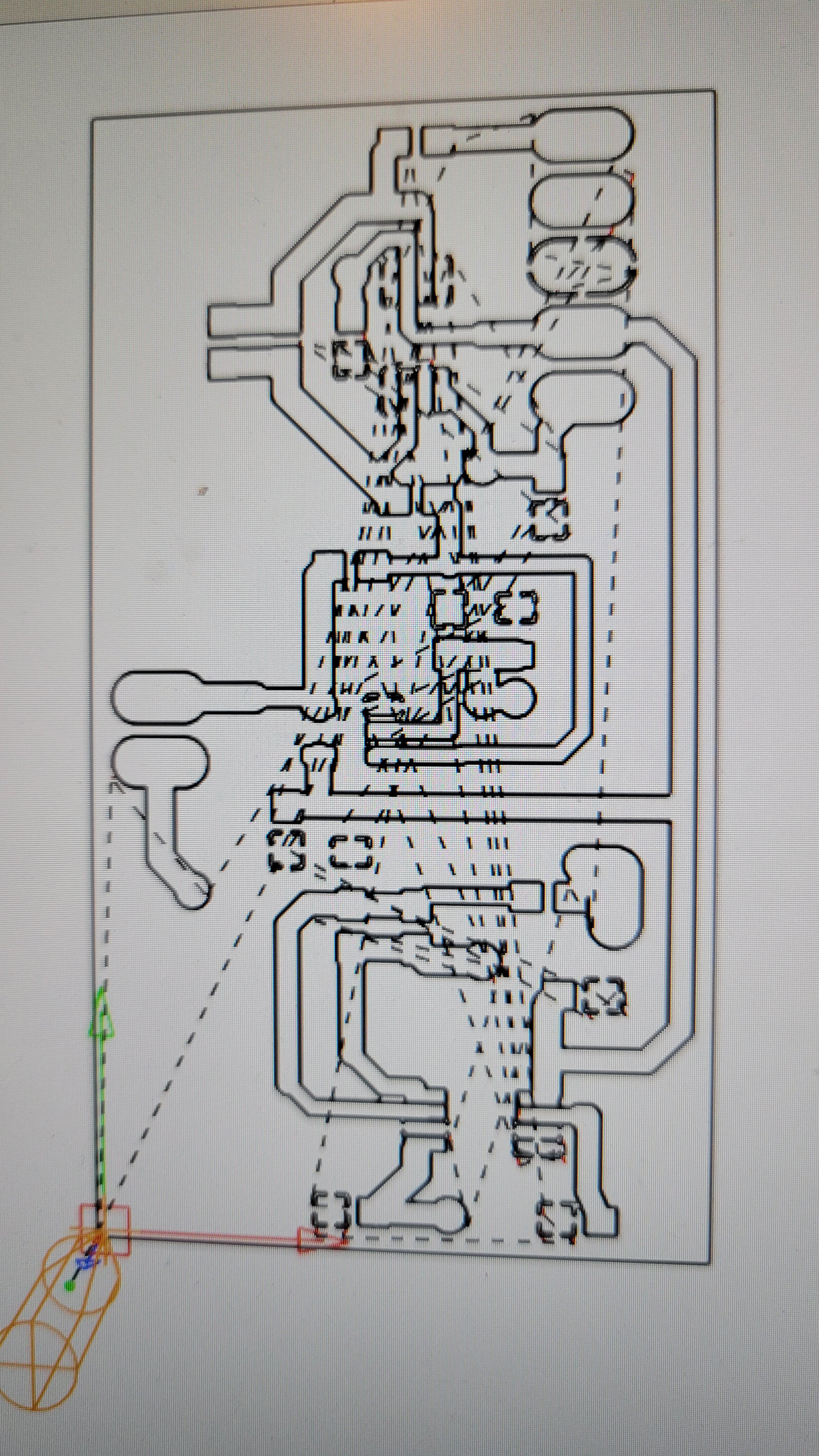
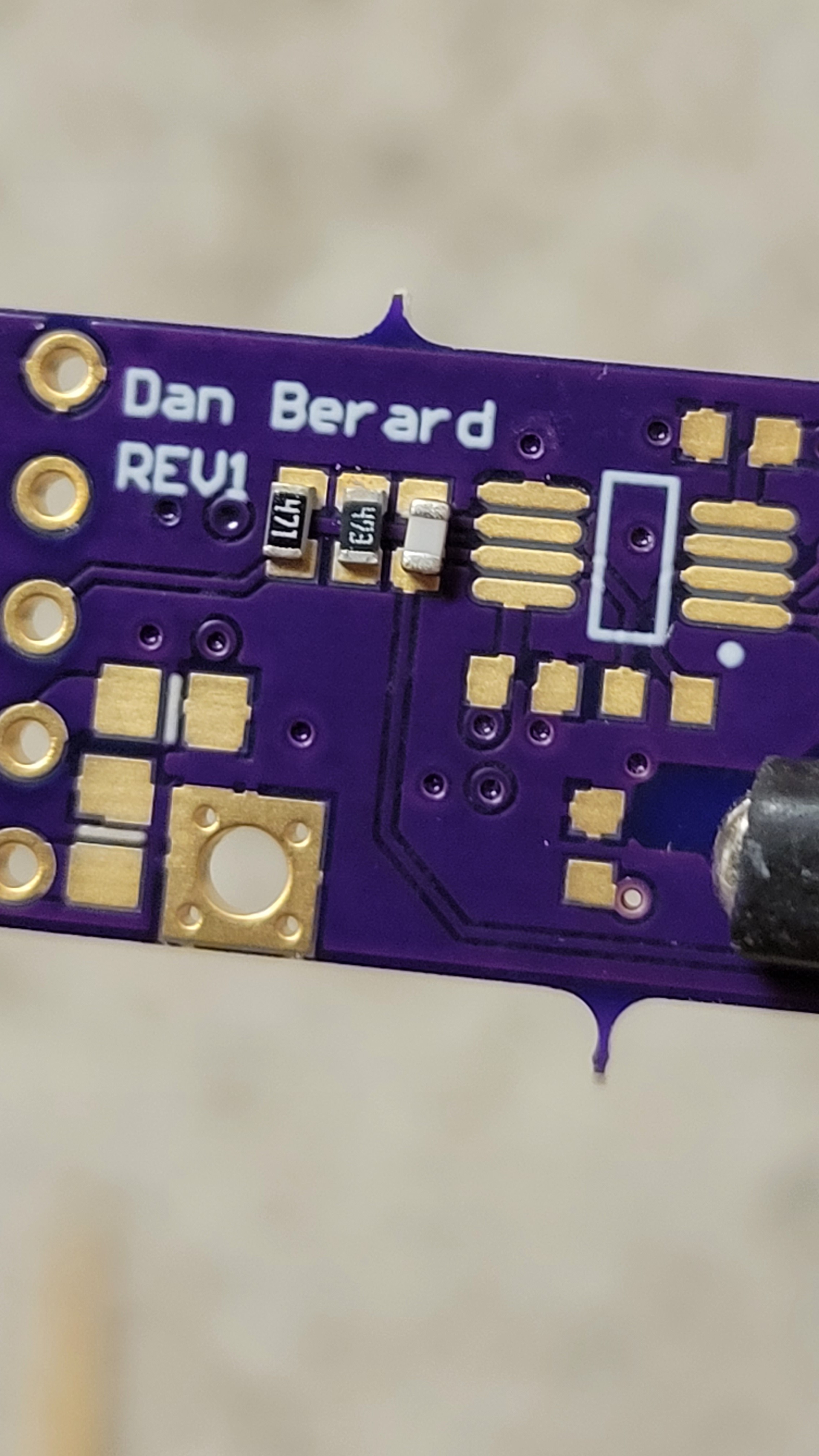
After couple of days I've tried to debug this PCB. I've decided to build my own version hopefully once I will start building I will understand what is the problem with the previous one.
![]()
It uses the same schematic as the previous just without the capacitor compensation thing.
GCode seems ok.
![]()
I've tried to make it not to dense, otherwise it hell to connect all the timy components.
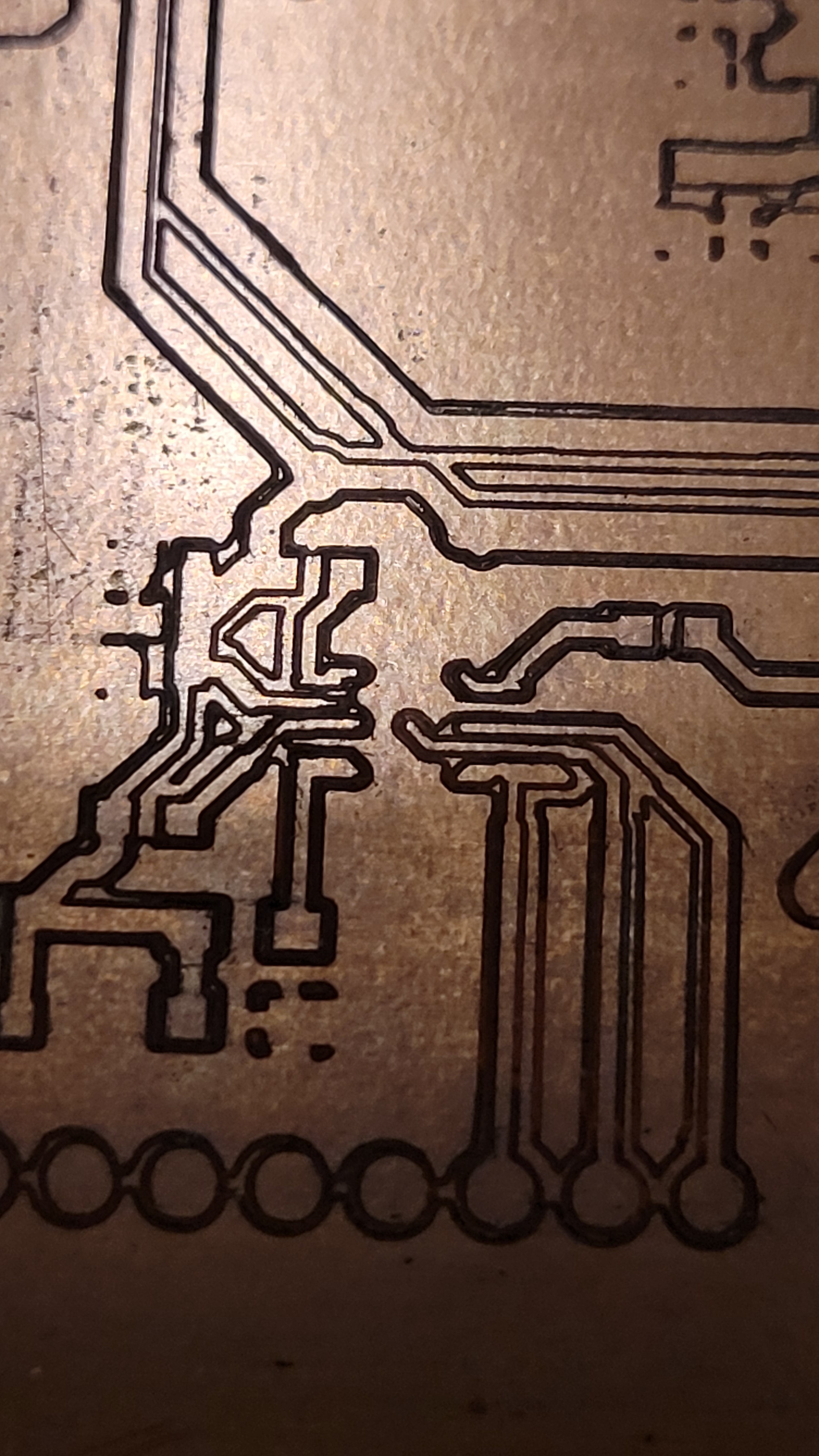
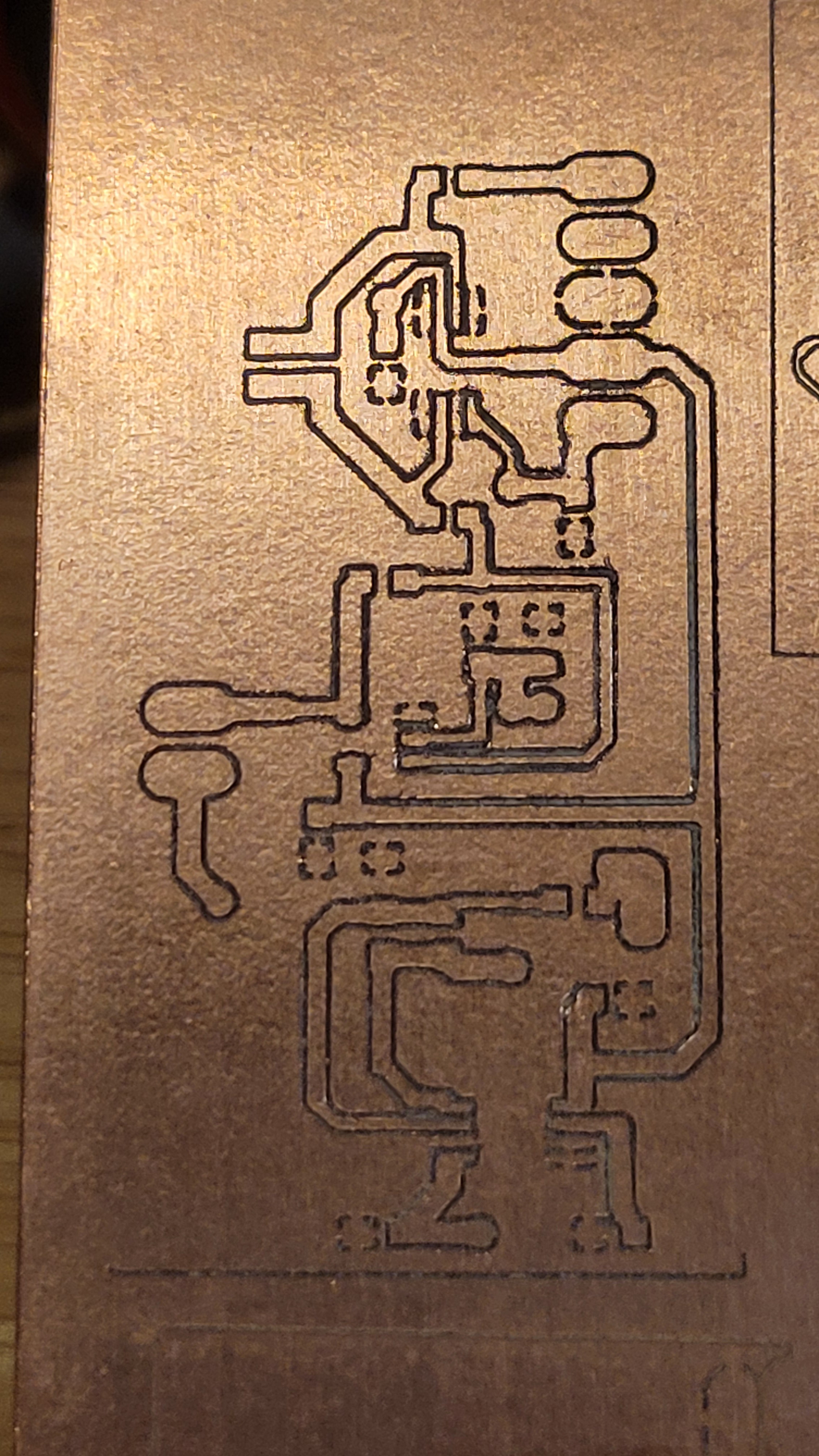
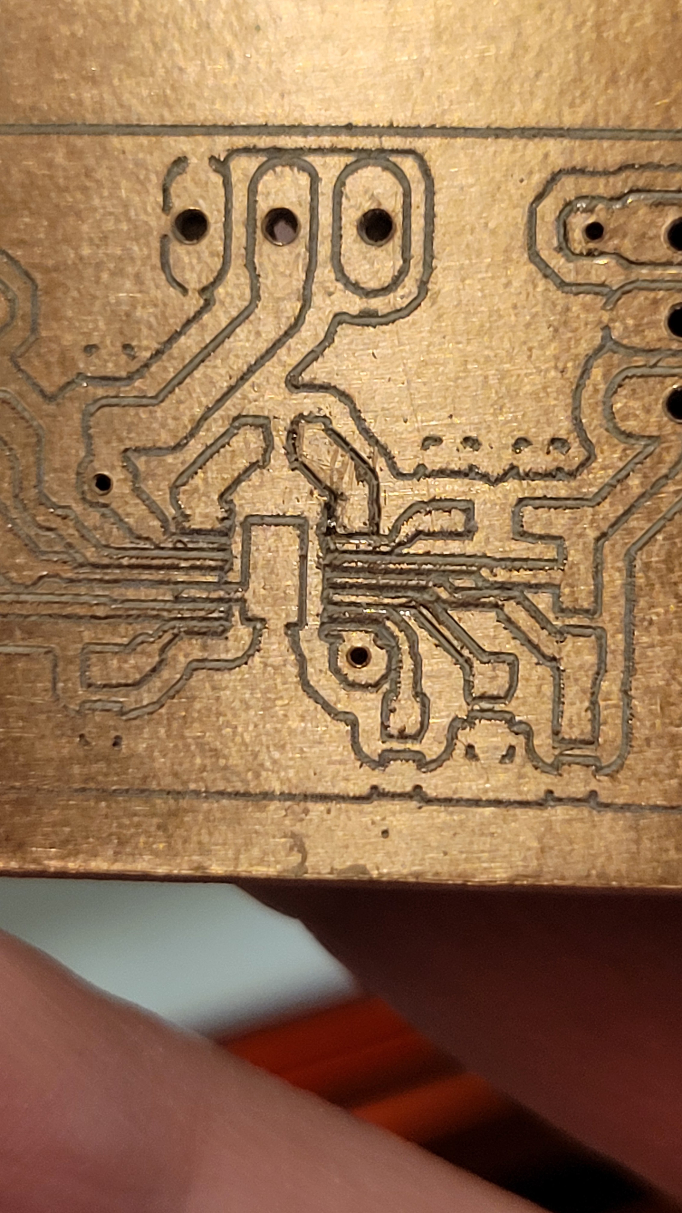
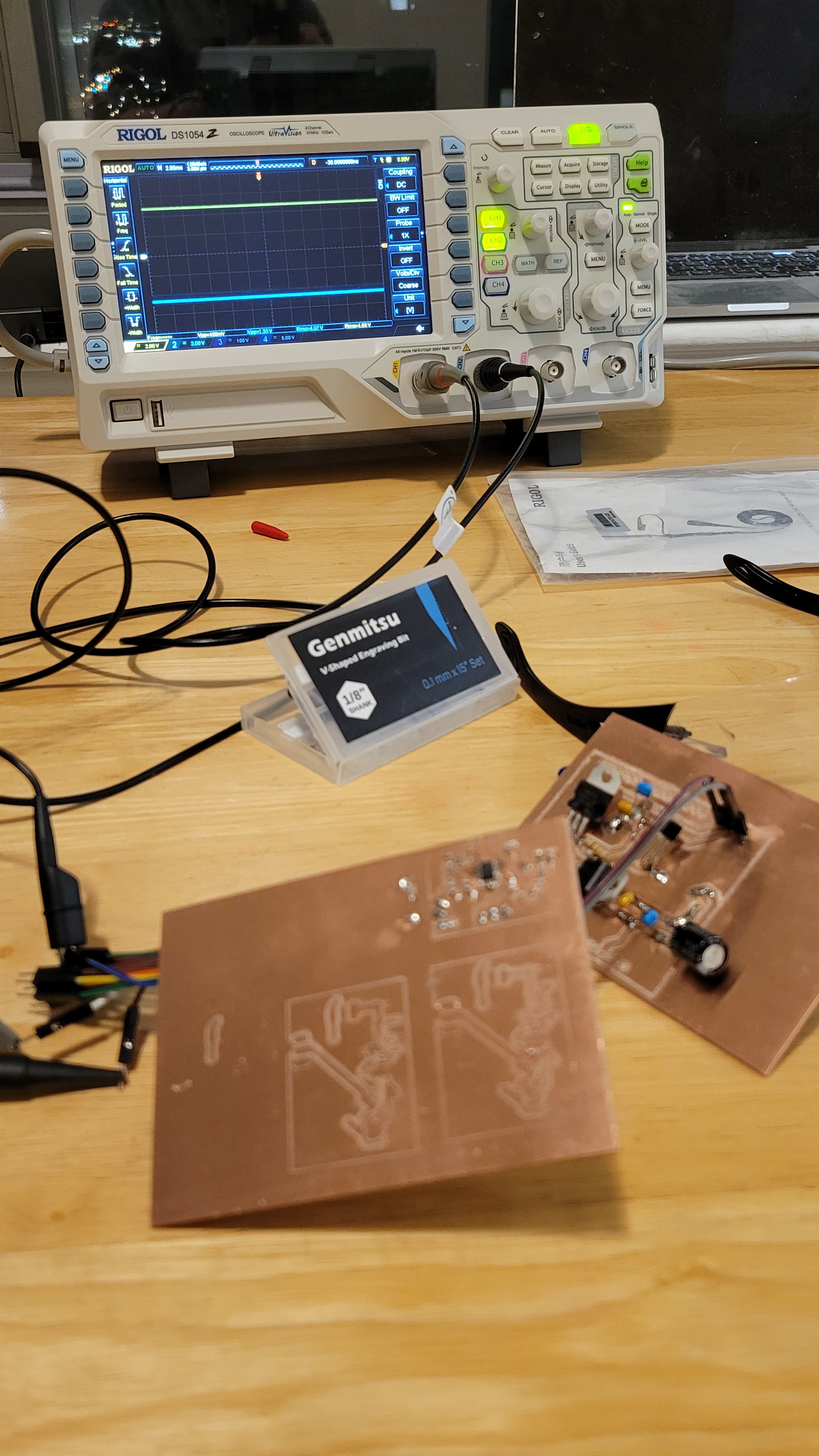
Printed the circuit using 15° 0.1mm v-bit.
![]()
The quality is really good and still there always some parasite connections that created because of the copper debris. After some cleaning and connectivity check it looks OK.
Next step is solder chip by chip and check that each step is working properly.
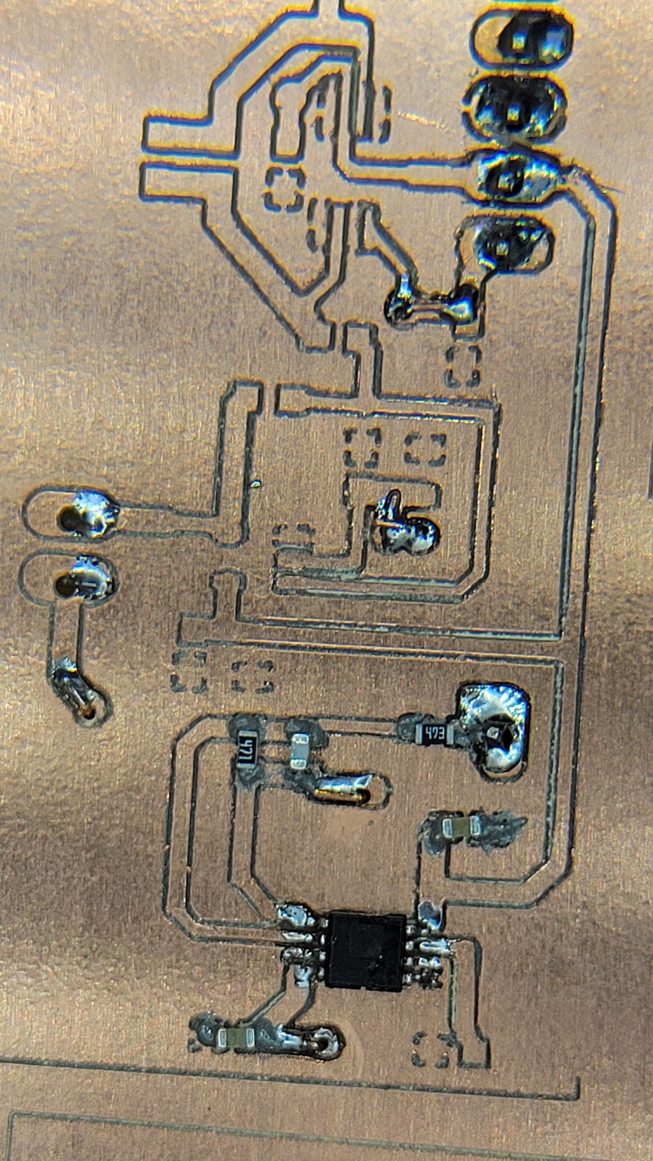
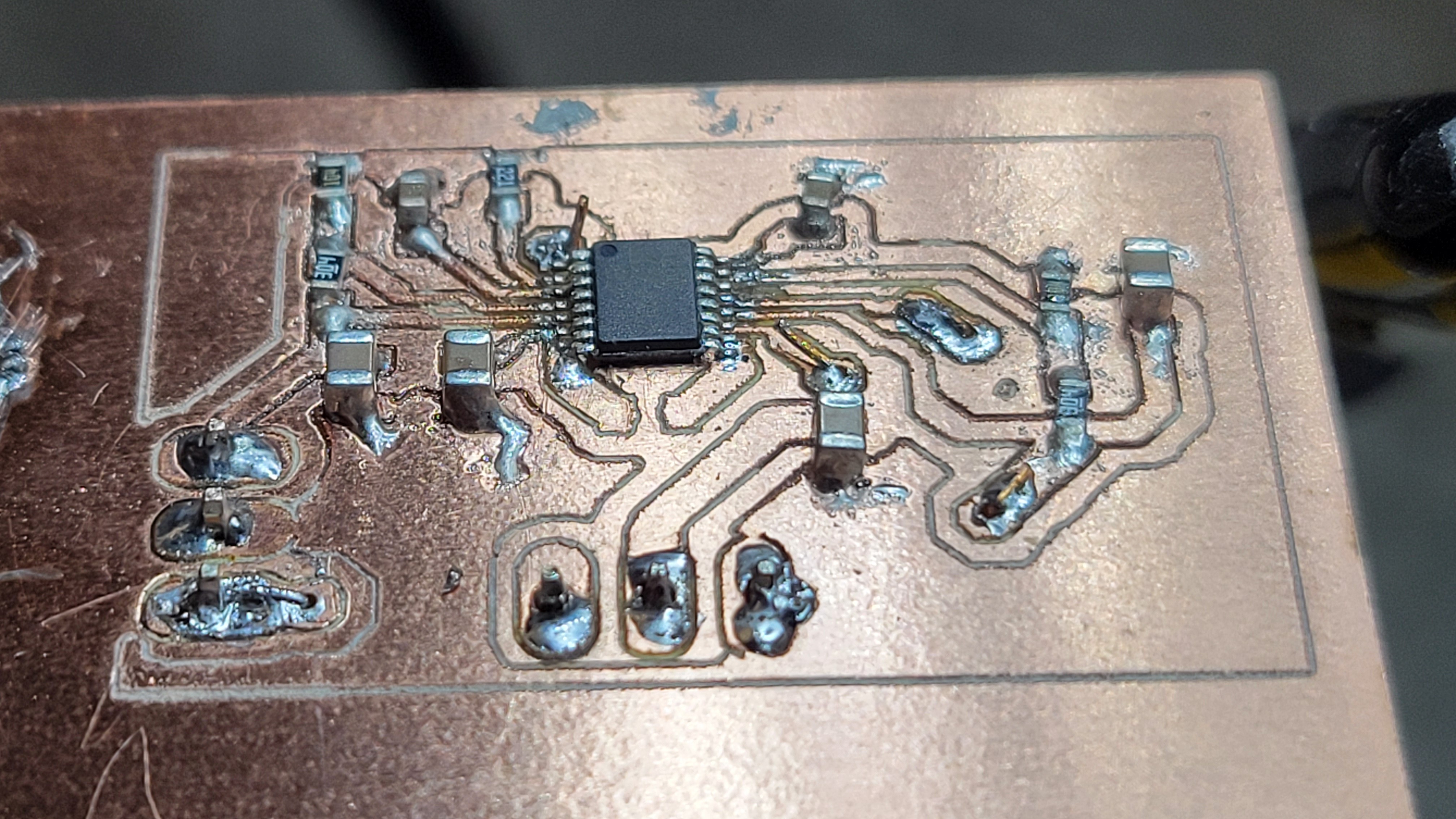
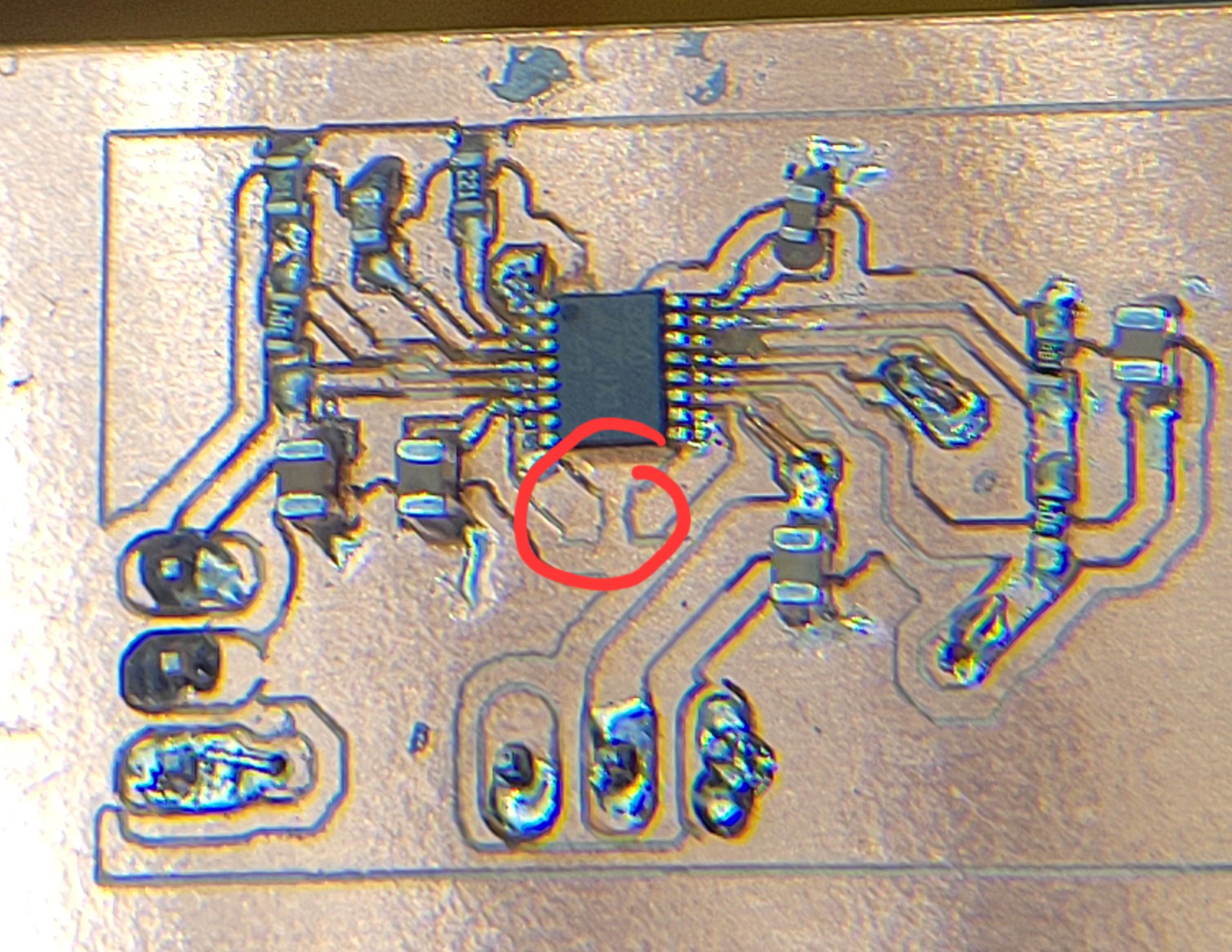
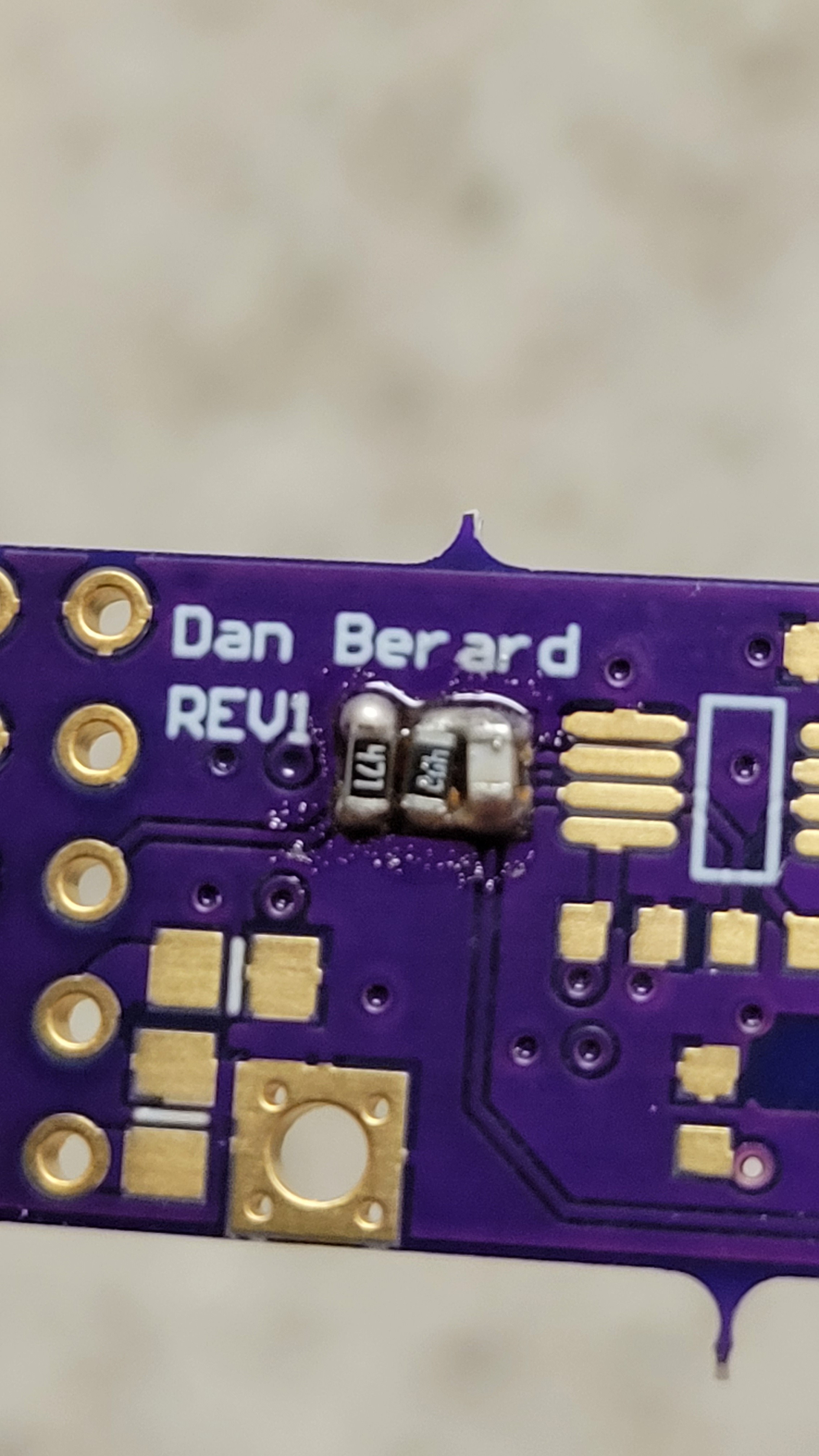
Careful placement of components
![]()
Gives lean result
![]()
I guess it's 'you reap what you sow'
Let's see if it's working as expected, it should get input from signal generator and attenuate it by 100.
After all the connections it's still not working. Changed to other AD8676 I had. Still same problem. Without power the resistors seems to propagate the signal. But once power applied everything goes down.
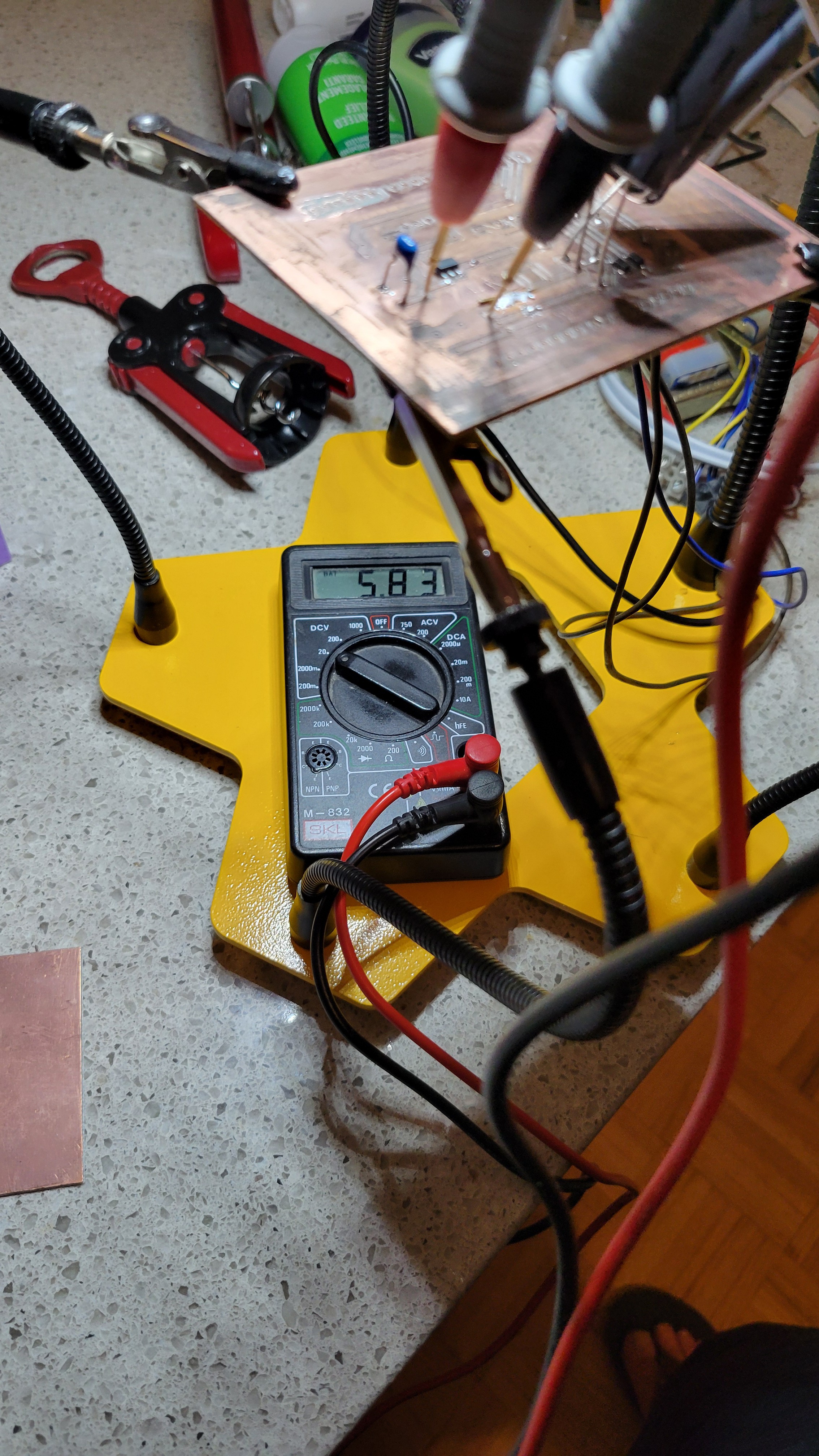
I've checked the power voltage it's only 4.6 and the minimal is 5v I was afraid to use 5v because of OPA656 it needs max 6 volts and I wanted to be on the safe side.
Let's try to increase voltage to 5.2v by using 430KOhm instead of 300KOhm.
----------------------------------------------------------------
Changed from 300KOhm to 430KOhm. The voltage is +5.6 and -4.6. That should be enough for our little omamp to come back to life. But what I get is only noise.
I am clueless....
I ran some simulations, with this configuration and 4v sinus input I we should get 40mV. Maybe the power rail high noise obscure it?
I'll have to test with old fashioned power supply wich doesn't have this switching noise.
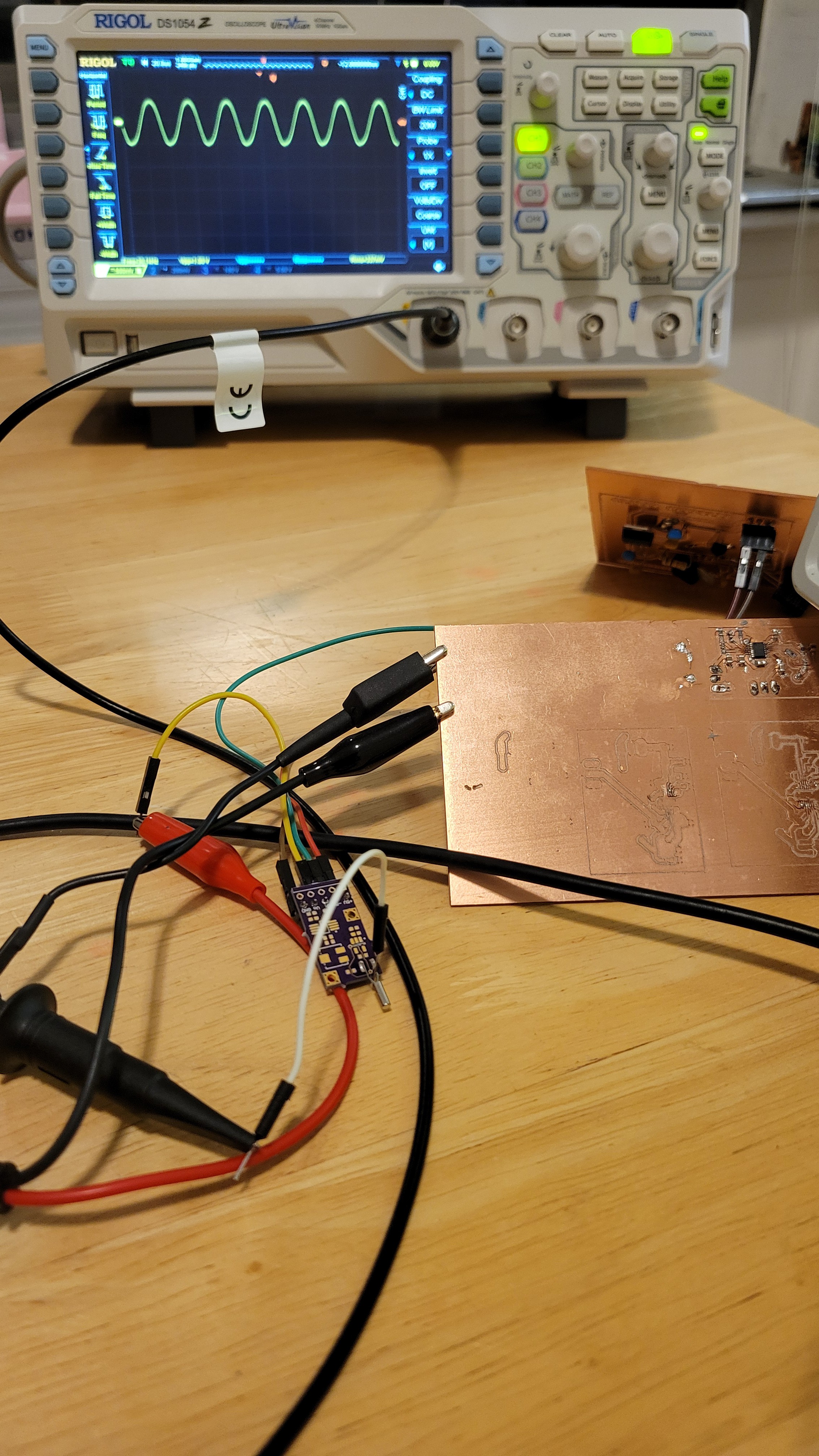
Yeah, that was it. Changed to old style power supply and got nice 50mV sinusoidal wave.
![]()
It's starting to get complicated as usual
![]()
It took me few long hours to connect OPA656n
![]()
Fingers crossed, if this will work we can see that electrical part of AFM as done.
Added output resistors, this way connecting oscilloscope would be easier.
![]()
Powered on and .... NOTHING
It just doesn't work... Started testing each board independently and power seems to work fine provided nice 5.4v and charge pump board creating positive and negative voltages until I connect the latest one. Once connected negative rail goes to zero. It turns out that the new board is short circuiting negative rail to ground.
I am pretty sure I've checked it. Funny that this happened on the factory printed board too. This time I know how to debug and fix it.
![]()
Problem fixed... Let's hope this time it will work
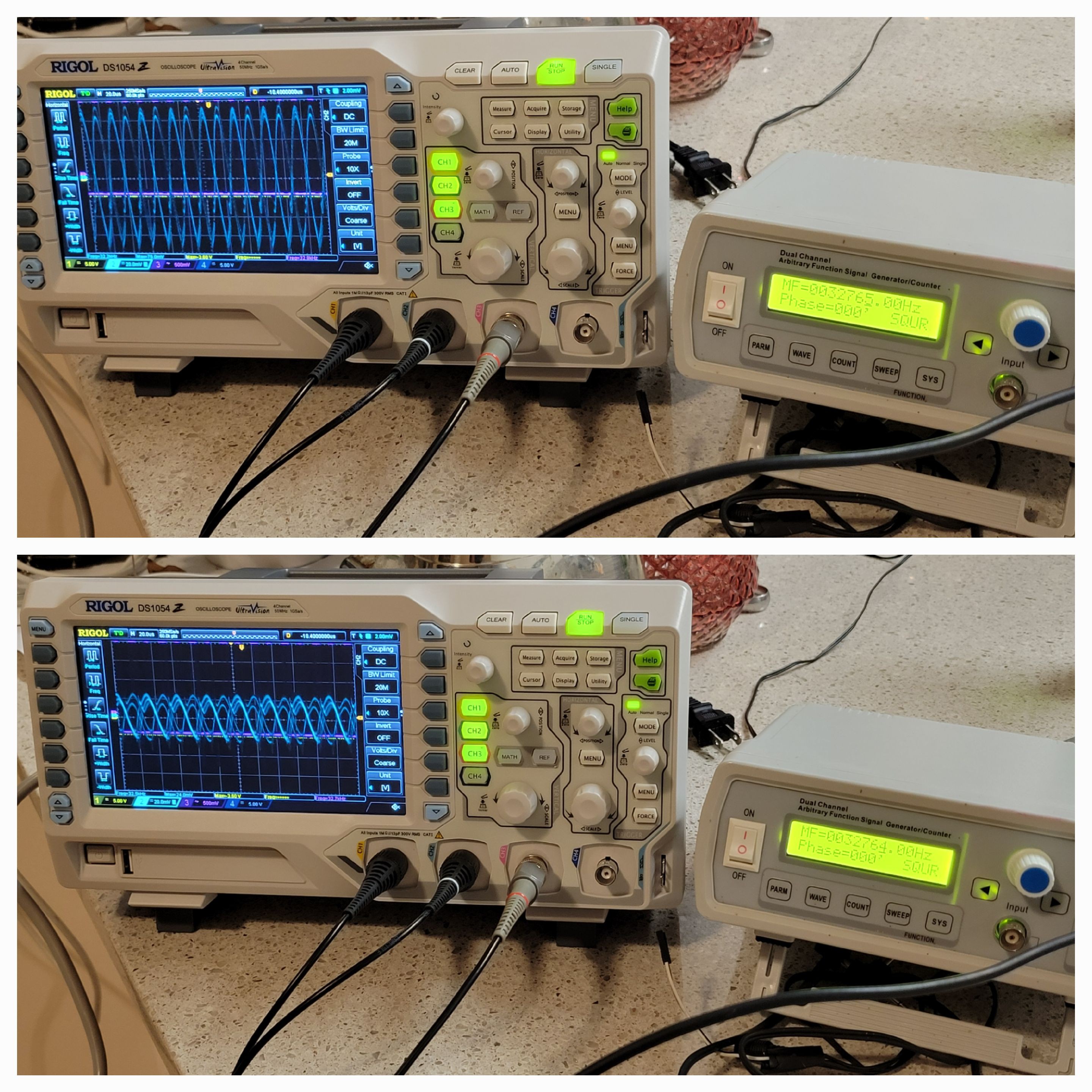
SUCCESS!! Finally, I was able to connect all the boards and input frequency of 32765Hz. I was shocked to see that one Hertz changed amplitude so much.
![]()
Also opened the quarz fork metallic case. Once opened frequency dropped by 5Hz and the peak was much lower as expected.
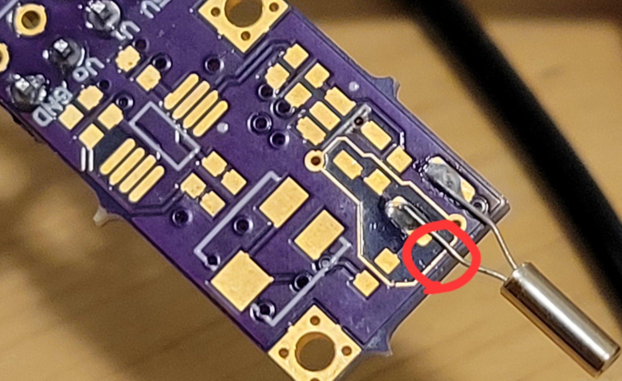
I had a problem with AD8675. Once I connected it the power would go down. First I thought it's my soldering problem. Then I thought it's faulty device. Nope, still short circuiting.
After long long time and numerous attempts, I found that the problem was what called NULL terminals. I was sure it should be connected to ground but it's something that else. I have disconnected them and left them floating, problem solved! Few, such a simple board and it took me so long to make it work. Although I still missing the capacitor compensation.
-
[Re-]designing PCBs
12/10/2023 at 05:47 • 0 commentsThe design is simple, the idea is to stack everything over standard Arduino board layout.
From Arduino I need only SCL,SDA and GND.
So, I will get one board for Arduino. Another one for power supply. Power supply will generate 12v and 5v only.( The double rail voltages will be created at each board that needs it). It's tempting to make the 12-(-12) and 5-(-5) voltages on the power board and route them to needed boards, but I am afraid long lines will add noise. Plus we prefer each board to has it's own voltages, this way we reduce inter component's noise.
Another observation is to use analog ground planes and not standard GND ones.
Some chips needs special layout like charge pump, so special care should be taken when designing them.
Another advantage of using stackable boards is each user potentially could choose which sensor to use.
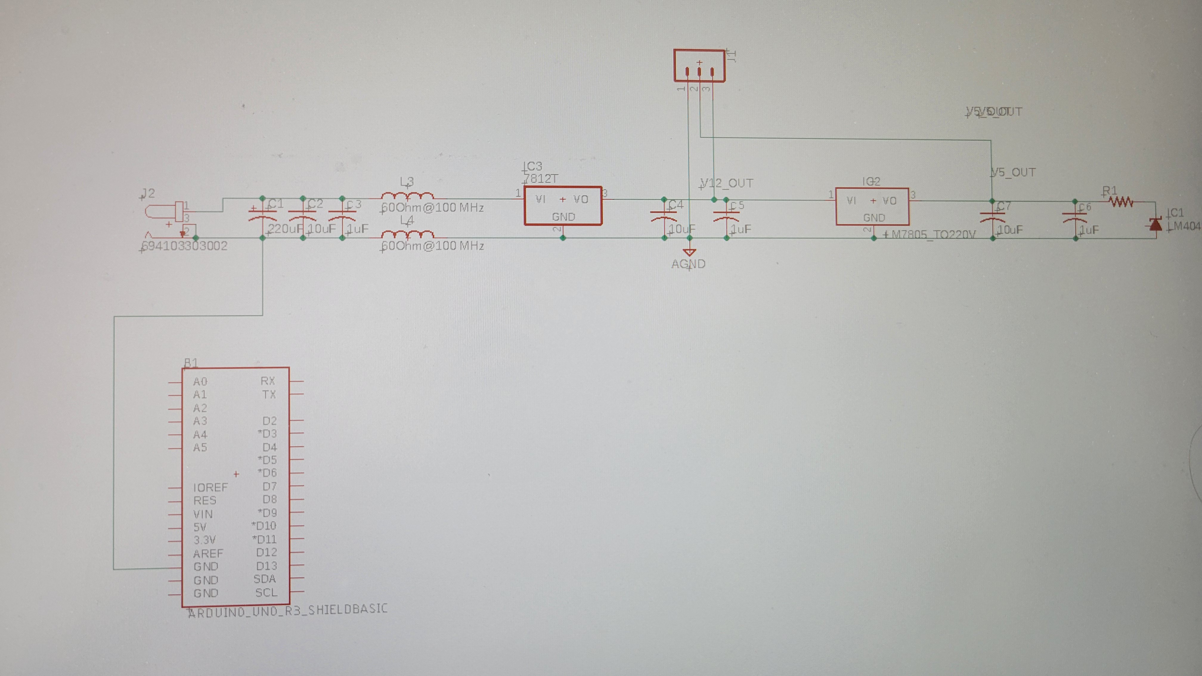
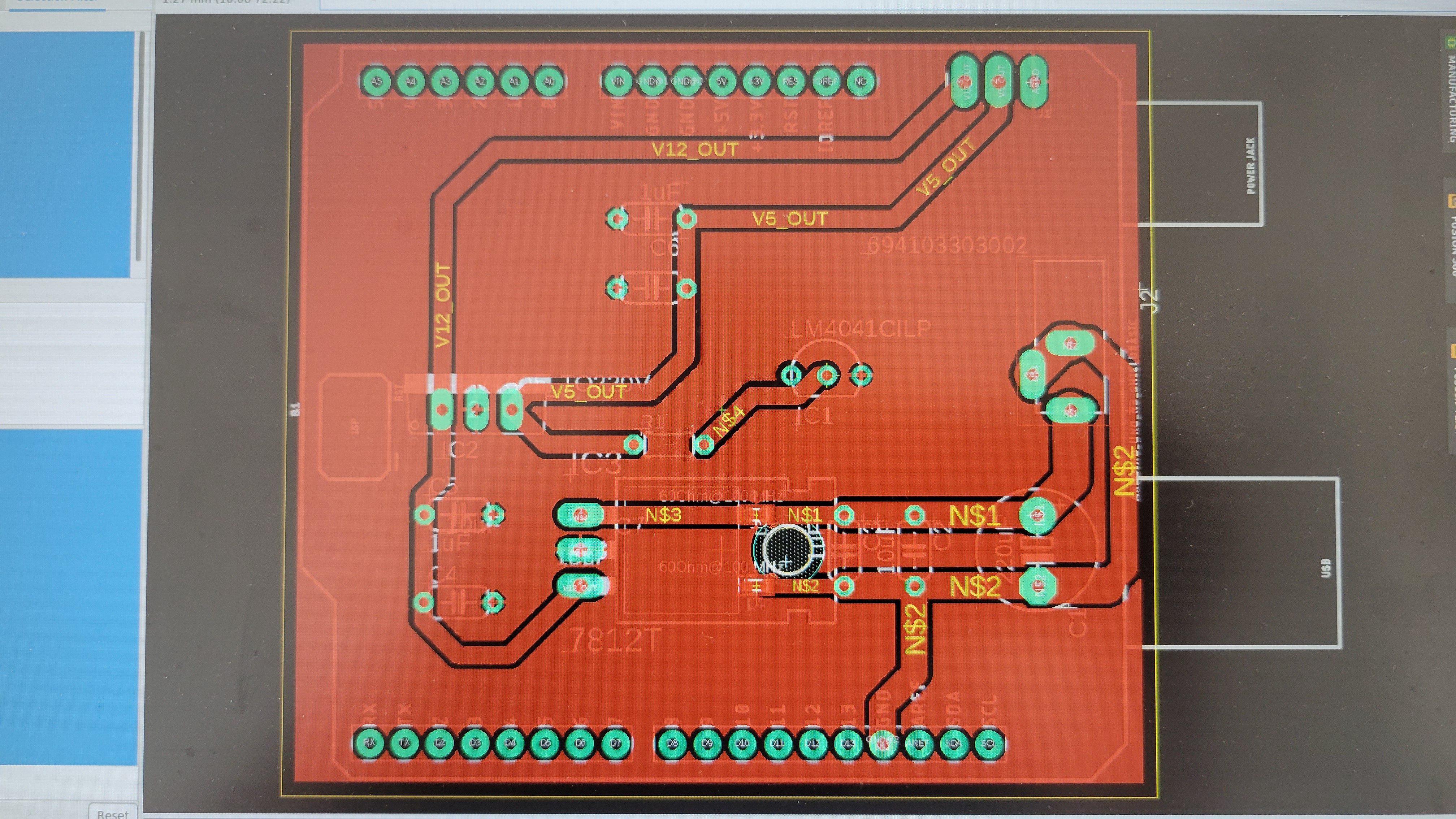
Ok, let's start with the main board which provides rectified voltages of 12v, 5v and analog ground.
![]()
And it's getting bit messier on Arduino shield...
![]()
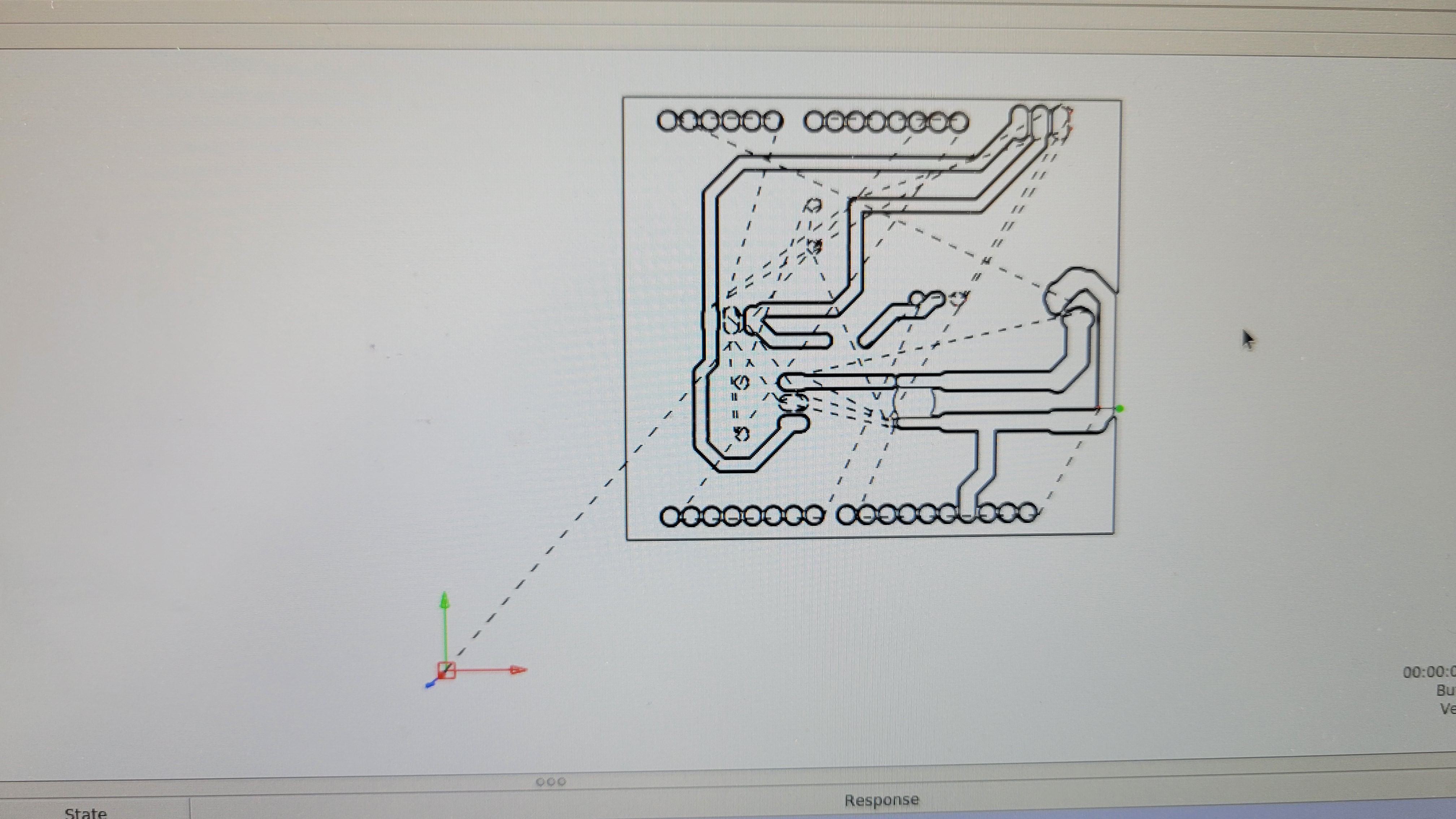
Converting it to GCode and sending to CNC/Candle software
![]()
Fingers crossed
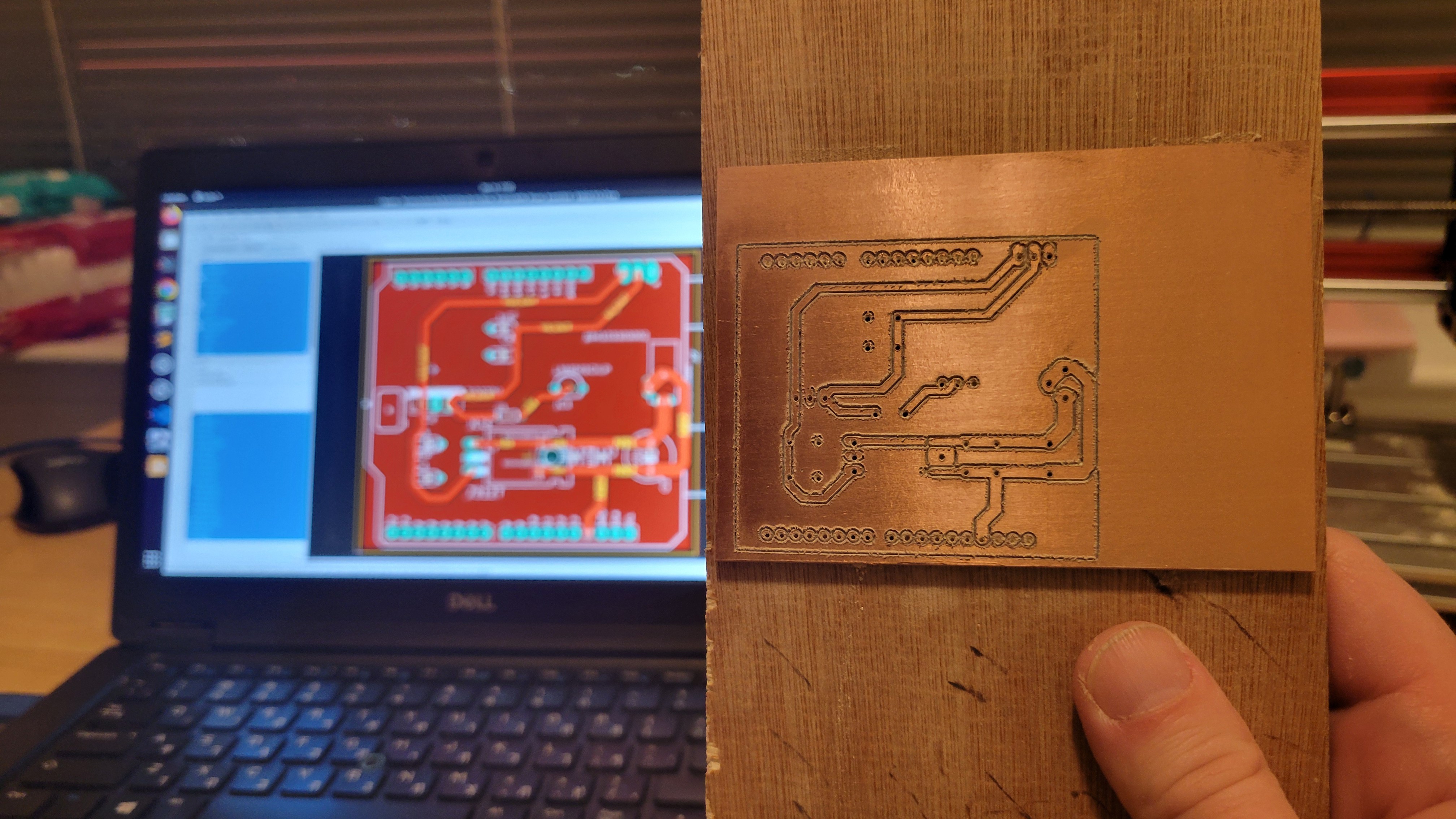
[Hour later... and lots of noise]
![]()
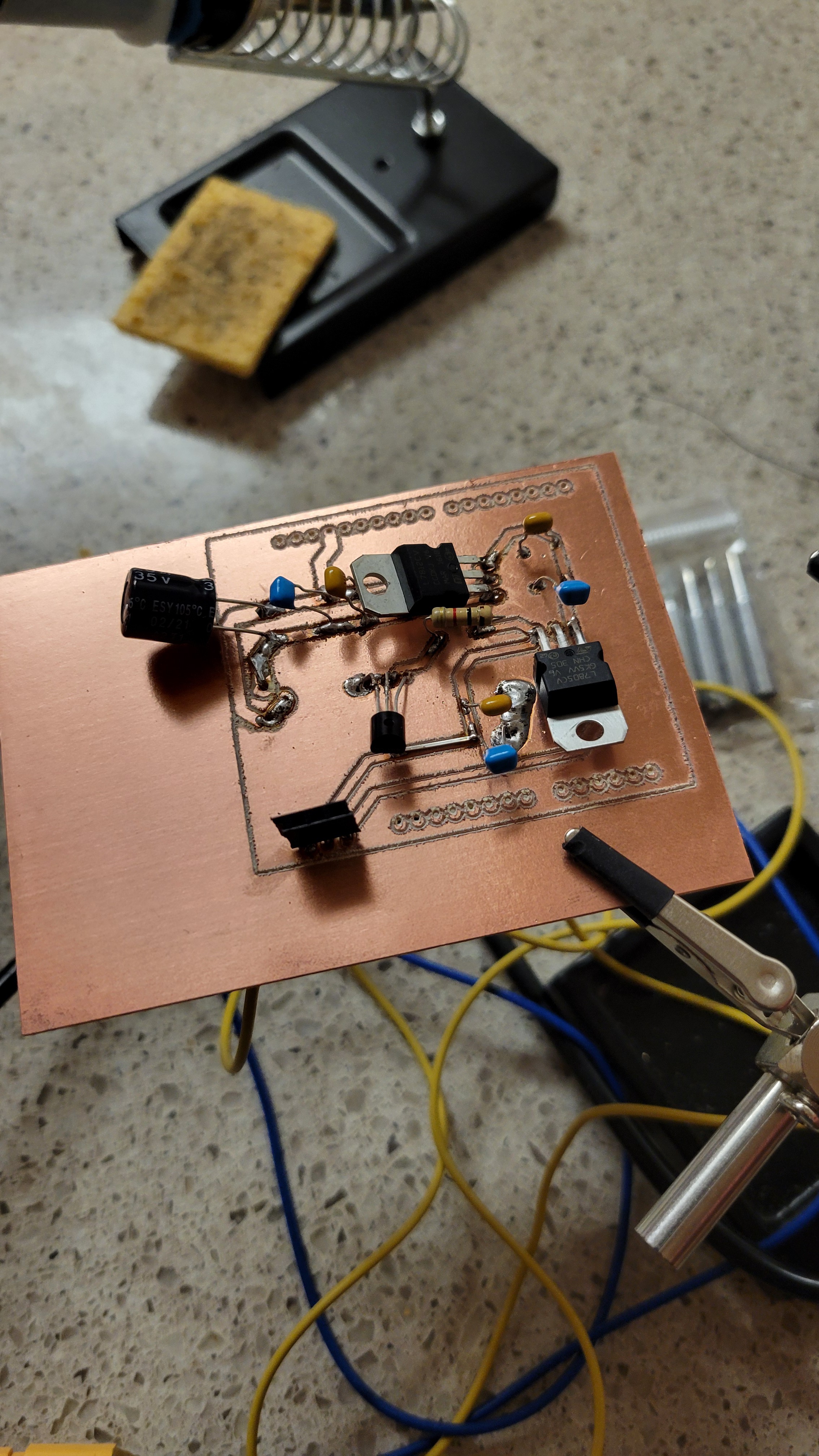
After two hours of soldering I got this:
![]()
It's bit ugly but does what it suppose to do.
5v and 11v. Wait what? Why 11? It should be 12v.
One thing I've learned is to use wider pads for soldering otherwise connectors just breaks.
Single to double rail, here I come...
Anyway, the input should be 14.5v to 27v.
Now let's start with input. We should get -5 to +5 voltage for OPA656N to work.
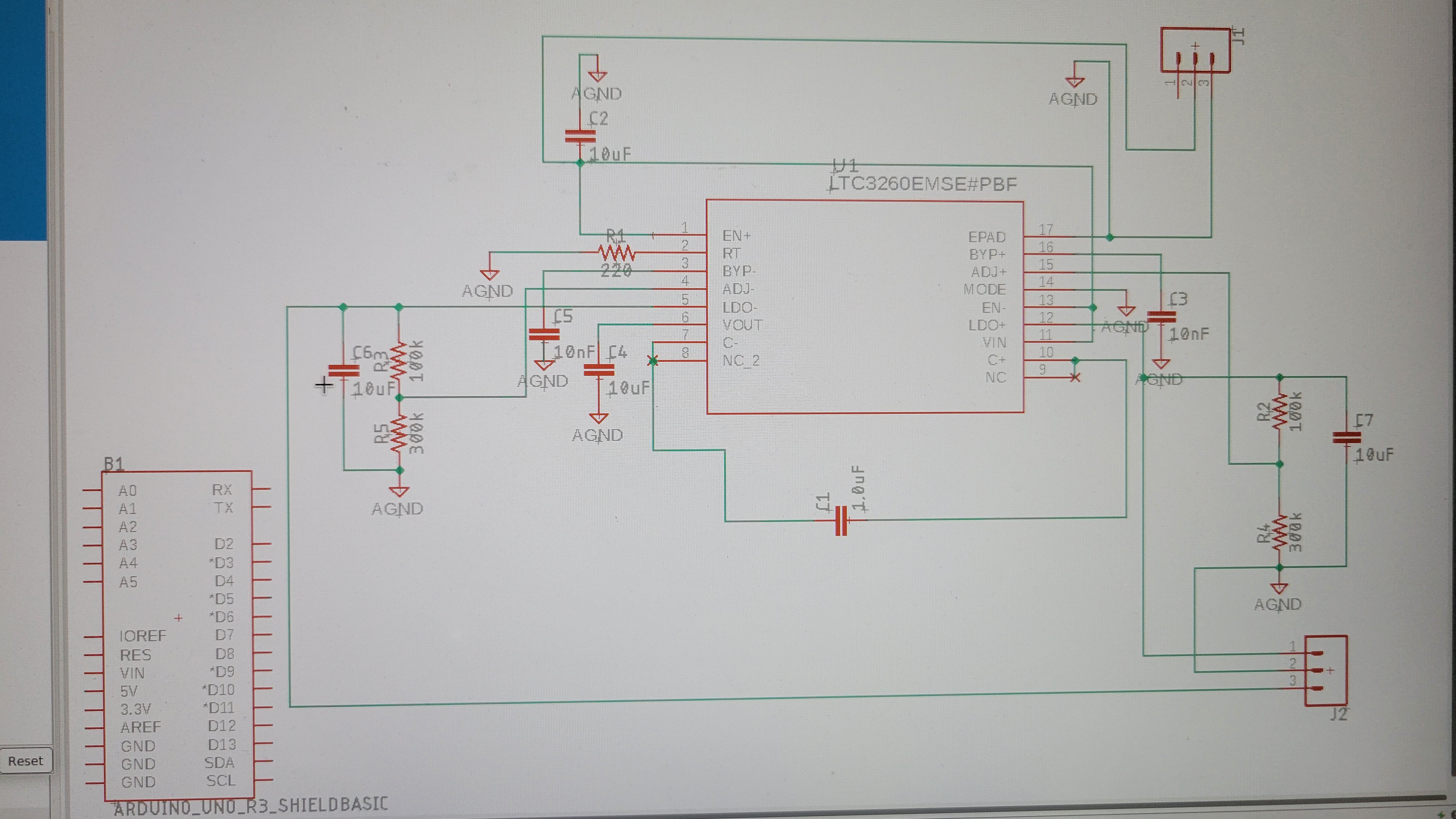
Here is the schematic for generating two rails from one, using LT3260. Most of the time took me to learn how to import LT3260 into The result
![]()
The routing/placement will by difficult
---++++----
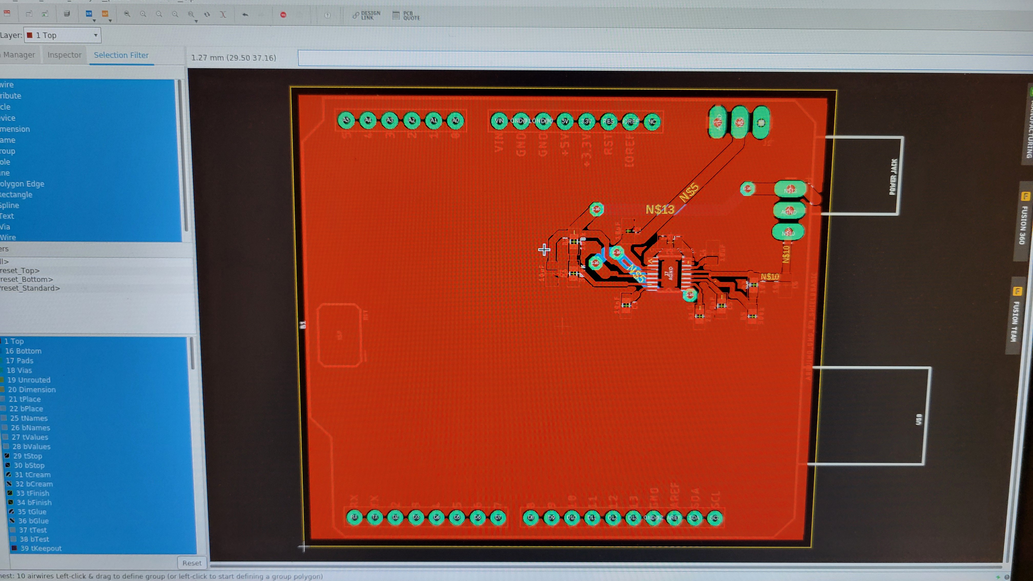
Actually it wasn't that difficult. I've used the one provided with LTC3260. I got this,
![]()
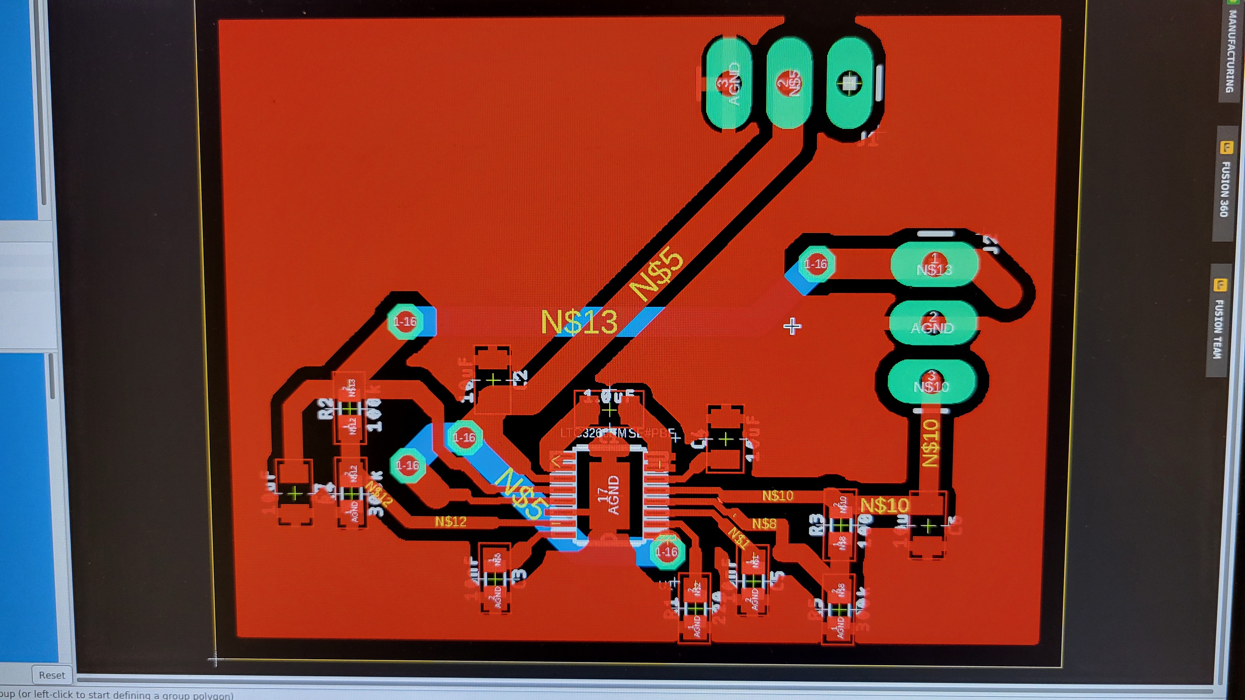
Let's zoom in..
![]()
Now it's time to print and test it.
I know this is suboptimal, the vias are huge and I don't use smaller than 0603 capacitors/resistors.
And this all because I create PCBs manually, no dual copper layer etc.
On the other hand, I can change those designs in matter of hours 🙂
First looked good by after some examination it turns out to be bad, on GCode level.
![]()
The second one got broken bit in the middle. And third got wrong height for some reason.
But fourth was much better,
![]()
More than I could ask from old and cheap CNC machine.
Checked the circuit for conductivity, one of the pads was short circuiting. Tried to fix it and bricked the PCB. Arrrr ...
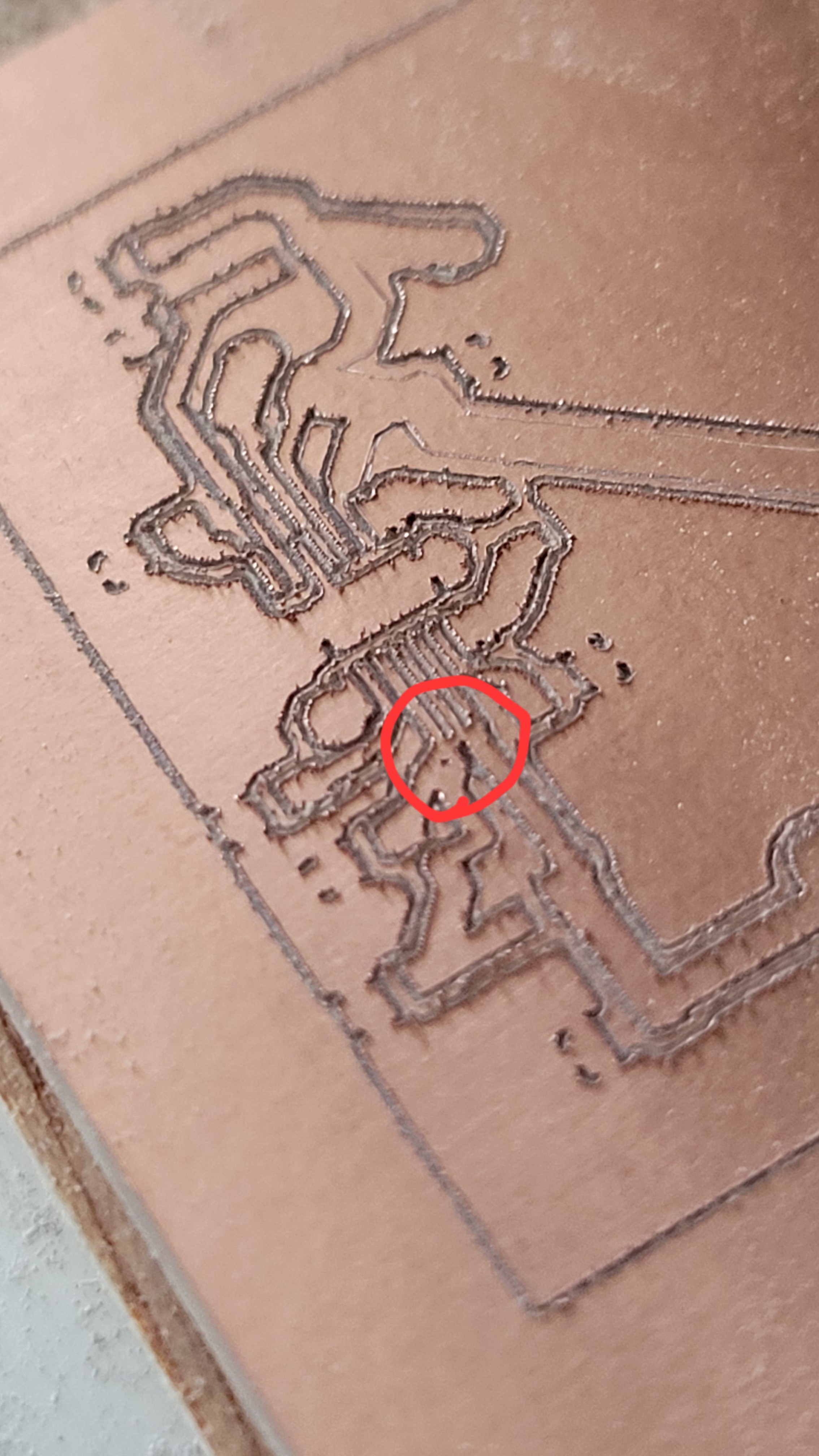
Another three attempts ended up with two broken bits and one successful print. Made smaller circuit so printing would be faster.
![]()
It looks worse than the previous one but electricity wise it is ok.
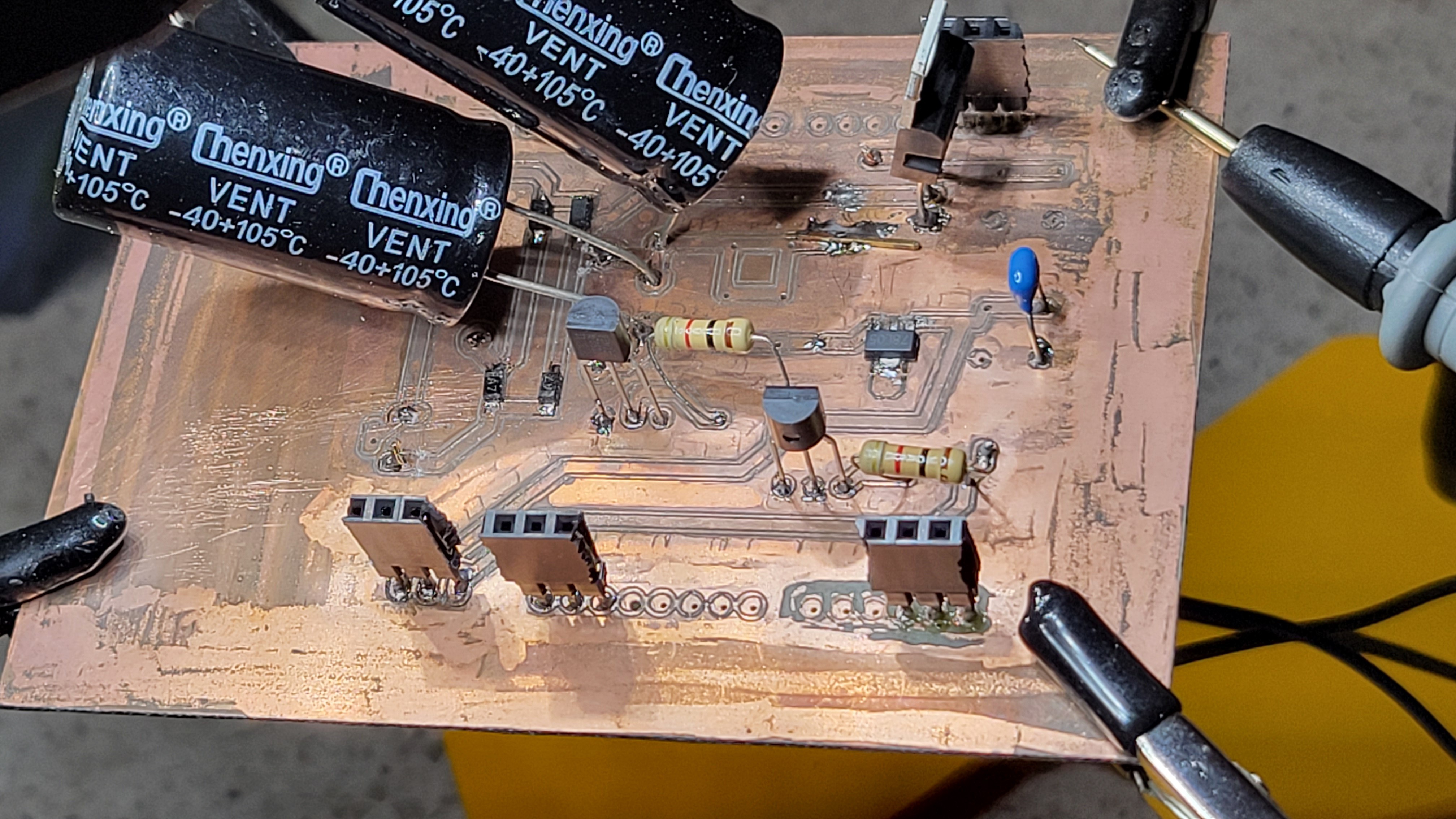
Added all the components, boys it only looks easy.
![]()
Soldering paste made things easier but components so tiny, it's crazy!
Checked all the lines, looks ok, except one. I hope I could fix it without bricking the PCB again.
The good news it's working!!
It's looks like I've made all possible mistakes one could think of.
First I managed to rotate power supply pins. Luckily I don't need Arduino inputs. Then from all capacitors I forgot charge pump capacitor.
![]()
After connecting those it still didn't work. I thought first that I burned the IC by connecting wrong polarity. Luckily I got -5v Vo (not LDO-) so it encouraged me to look for a bug. Then I found that the problematic line was not problem with IC pins but near capacitors. Finally another problem was pin that was not properly connected, so when I checked it with Fluck it looked connected, but actually it was floating. Resoldering the pins gave finally the long waited results
![]()
With stable output voltage
![]()
-
Building my own PCBs
12/06/2023 at 14:44 • 0 commentsIt may sound like going two steps back, but it worth it. One of the problem with such projects is that they're hard to reproduce. It is hard to do such project with breadboard. I've tried and burned my charge pump(single to double rail dc-dc converter) since I moved wrong resistor in the jungle of resistors on the output stage.
So, I needed to go back to the beginning and do it right. I thought of printing delicate SMD connector using laser module and on 3D printer but it creates dangerous fumes, arrr... Then I've stumbled on video about creating SMD with CNC 3018, WHAT?! Is it even possible? I had to check it out.
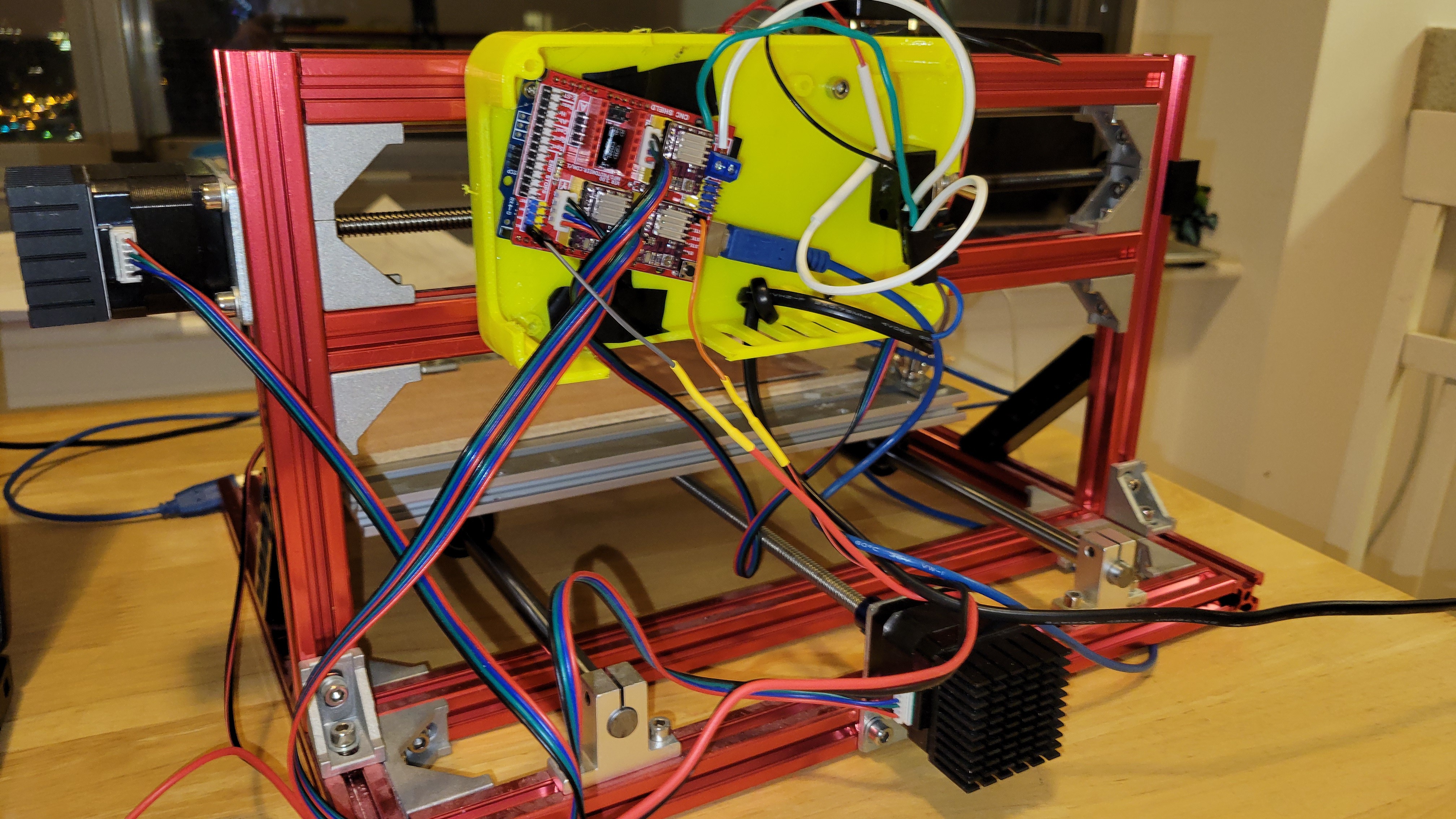
My old cheap 3018 CNC, had controller damaged so I had to replace with even cheaper CNC shield v3 that was laying around idle. After connecting/compiling/installing/tuning I finally got my CNC back.
![]()
Ugly but doing it's job.
Now I started to play with height map, it's important for such delicate components like 0.5mm pitched SMDs.
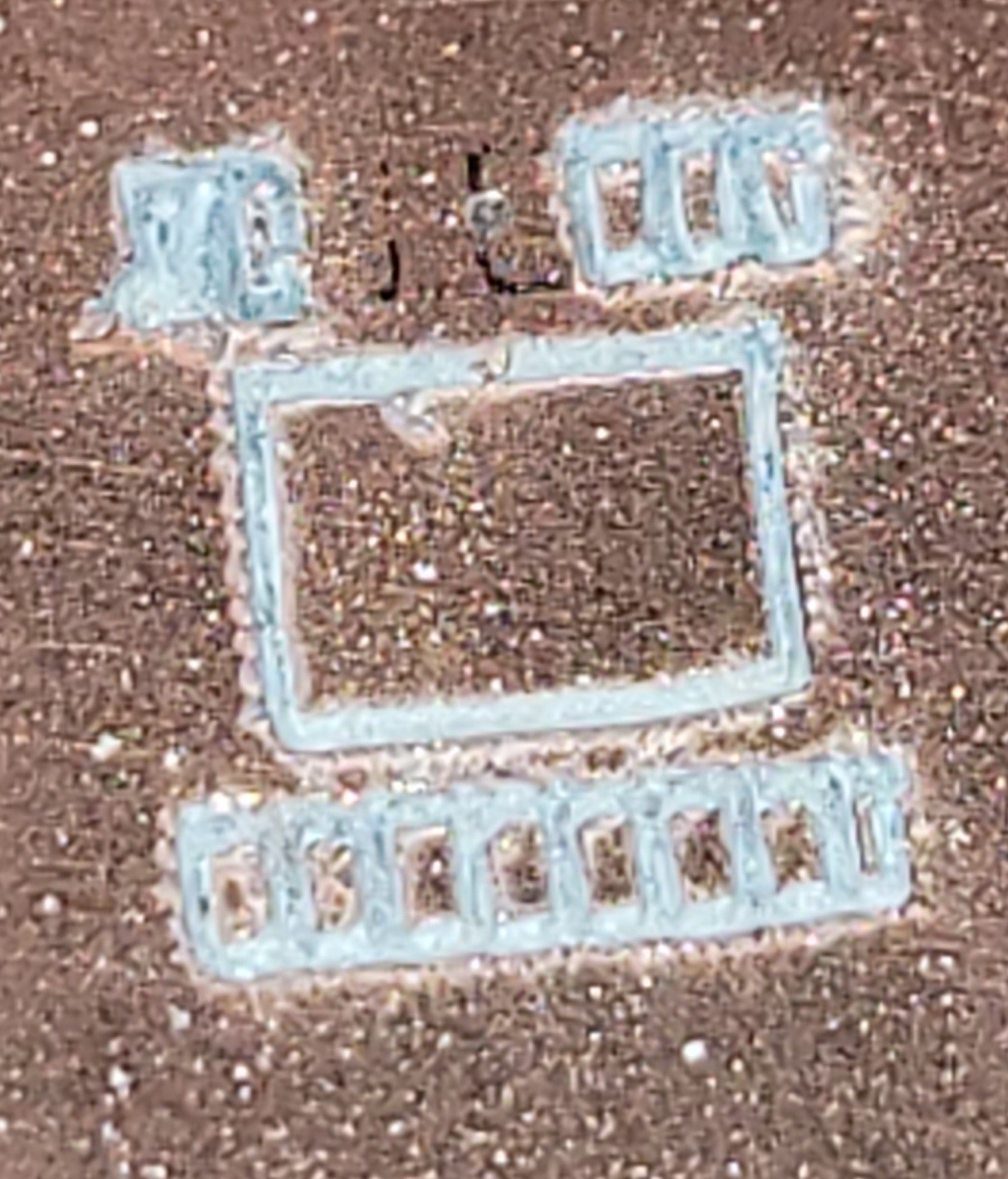
After some tuning on the fly, I got my first SMD connector.
![]()
This is a test of LTC3260 0.65mm pitched layout
![]()
It's promising especially given the fact that it was made with old and bit broken bit. Results can be improved even further.
Now, PCB can be created in matter of hours and I don't have to wait two weeks for each PCB iteration.
It was worth the time invested 😀
After inserting new/sharp bit I got quite satisfying results
![]()
It good for development, the final board will be printed using one of many fabs out there, that print PCBs.
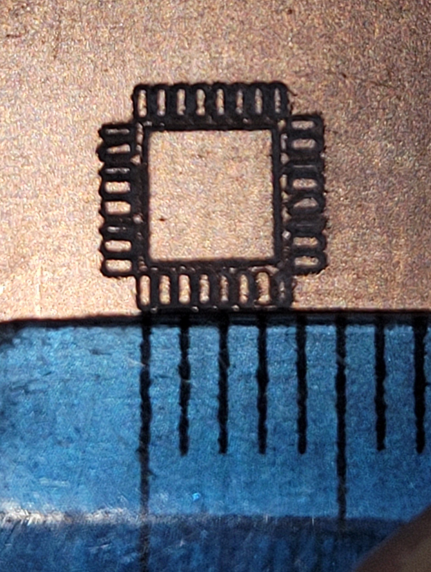
Now let's run example with 0.5mm pitch
![]()
Not bad for standard 30° bit. I guess 20° or 15° can make even better resulta.
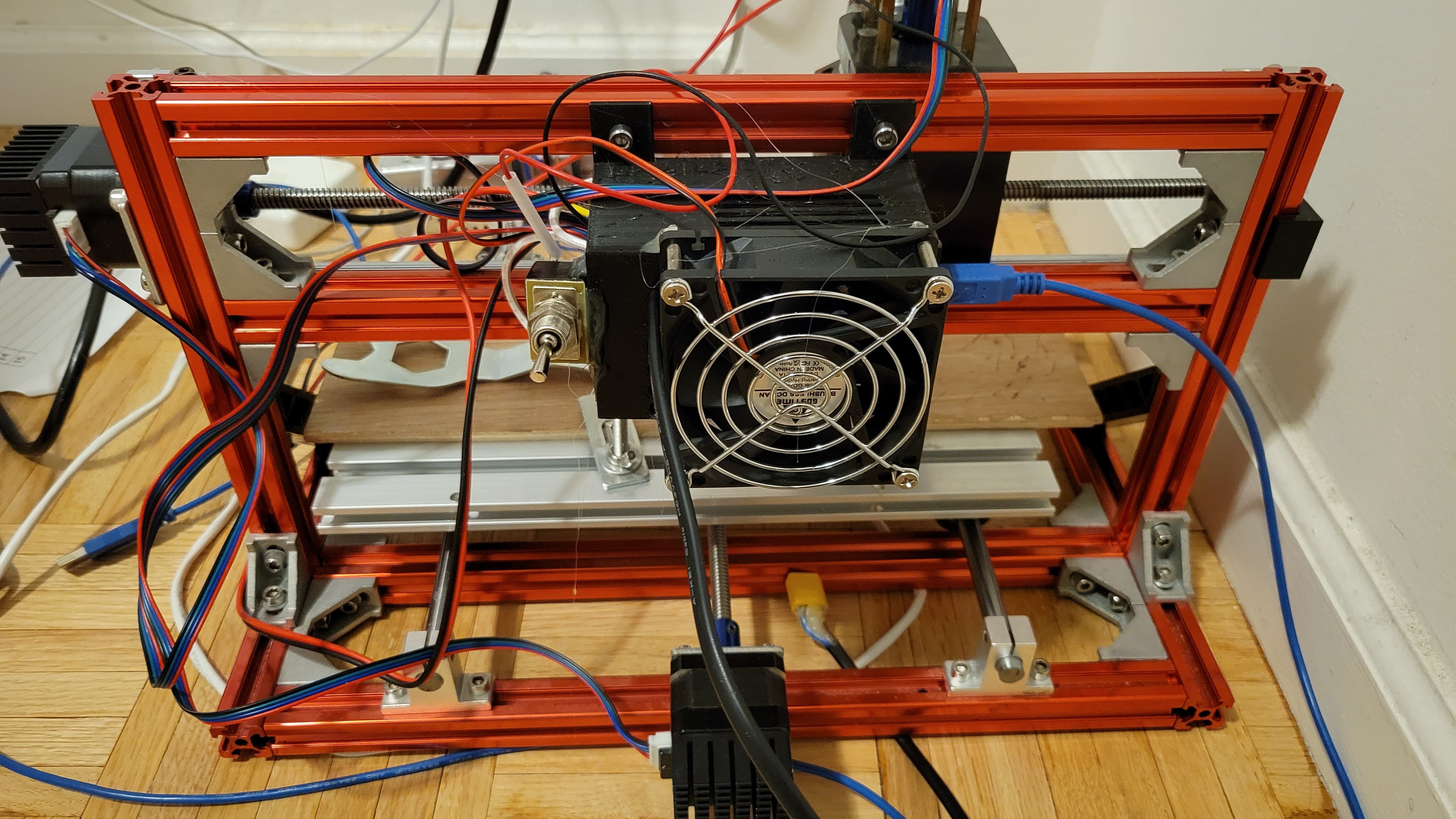
In order to use high precision for my PCB, I used DRV8825 motor drivers. With setup of 1/32 step. But it got it's price, drivers got super hot and I got automatic shutdown. To prevent this I printed this nice box and vent to cool down everything.
![]()
Another necessary step back from my cause.
-
Soldering SMD
12/01/2023 at 20:52 • 0 commentsGot the components and the boards, fhew, it took so much time!
Last time I tried to solder tiny SMD components it was so messy, I thought I will try easier method of solder paste.
Step one find a victim
![]()
Let's say this tiny cute 500 ohm resistor of 0603 size code and some PCB board I don't need anymore.
Put some solder paste...
![]()
Oops, I got him all covered and hopefully not lost. Now I started my hot air gun, and it's become quite funny since the resistor started to swim inside the paste. Although it funny on demo, it won't be funny once it displaced on real PCB board. Maybe I should use slow air stream.
Lower air speed and 250°c done the job
![]()
Not as pretty as I wanted to be but I think it will do for now.
Take 2, less paste, wider air gun nozzle and I got much better result.
![]()
Let's try two simultaneously, if this goes well we can try the real thing.
Ok, sanity check ✅ let's put some components together just before the big mess...
![]()
And soldering....
![]()
Not bad for first try... Oh, wait a minute I got resistors switched... The first one should be the 47K... Arrrr...
I took me two hours soldering and de-soldering to get to
![]()
Not bad but it's only half of the board... Alas!!!
At this point we got only attenuator IC, I thought I would be a good idea to test it. We already know what shows be, we did it in the early stages of this project back then it was breadboard and single rail. Now we have a nice PCB and double rail for power. Instead of making new one we can decrease change pump from 12v to 5v. Easy....
It's just change one resistor for each rail. Positive changed to +4.5 but the negative is still on -12v. What?! Why?!
After few hours of poking each pin and trying to understand what is going on, it looks like it is broken.
It's quite annoying to go back and fix already working parts.
-
Don't re-invent the wheel
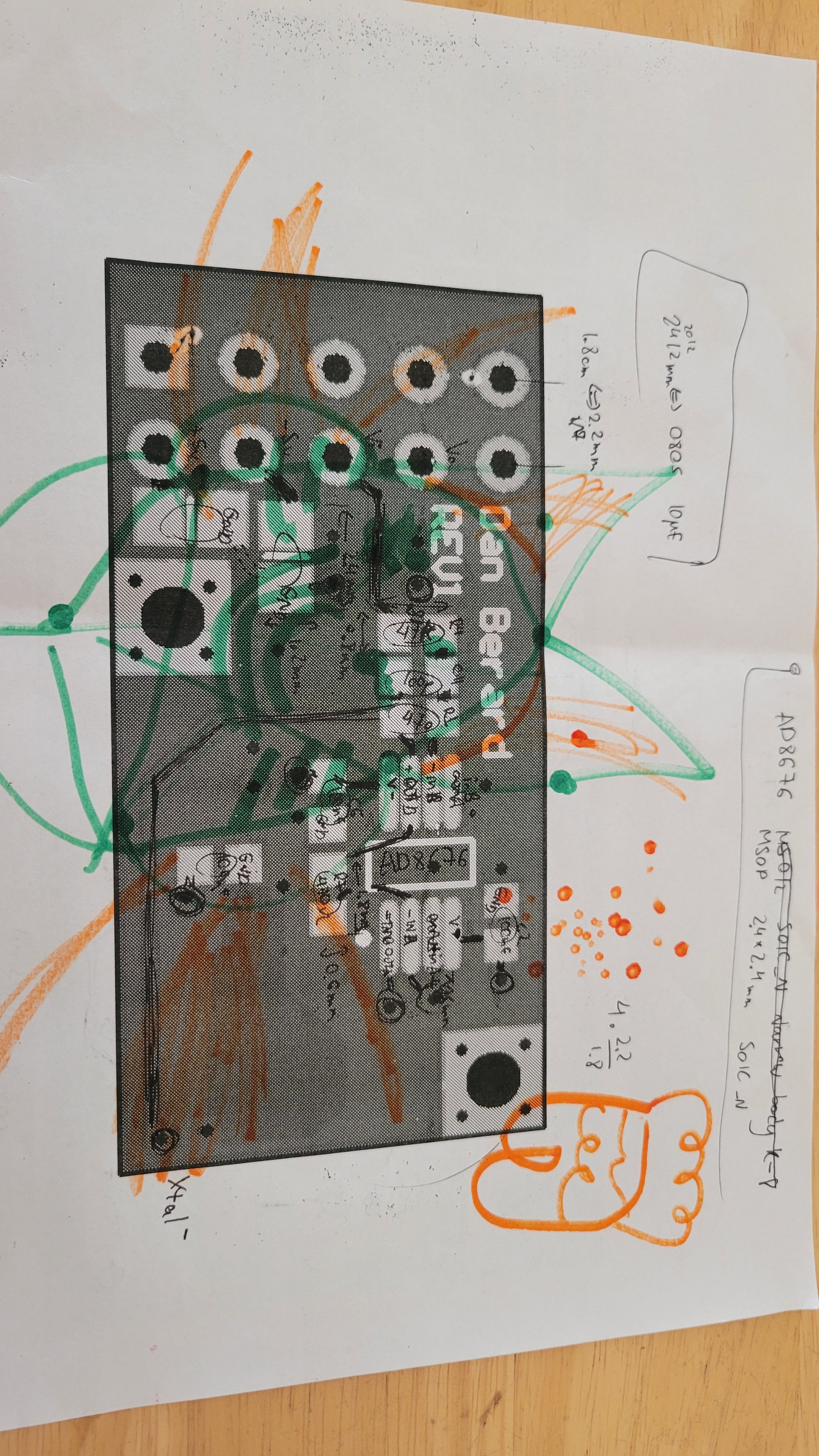
11/10/2023 at 05:20 • 0 commentsI thought that it could be a good idea not to re-inventing the wheel this time. I have a great post from Dan Berard. In his post https://hackaday.io/project/5713/logs he explain how to do the last electronic piece that I don't have. The amplifier that will amplify the tiny Quartz fork movement and convert to standard voltage signal, signal which could be picked up by standard ADC and then to some kind of DSP.
Sounds easy, right? Well here things started to go little bit south. I bought the board it's only 5$ for 3 pieces. (I don't have machinery that could do sub millimeter PCB boards so, sounds like a good deal) bought all the amplifiers just to find out that I got it wrong and I bought the wrong layout... Arrr!!! Plus I don't know what sizes of the resistors/capacitors.
I paid for the board like week ago and still nothing...
I guess I should buy nice laser and print such circuits by myself, it will take an hour ...
Arrr!!! Hate to wait....
-------------------------------
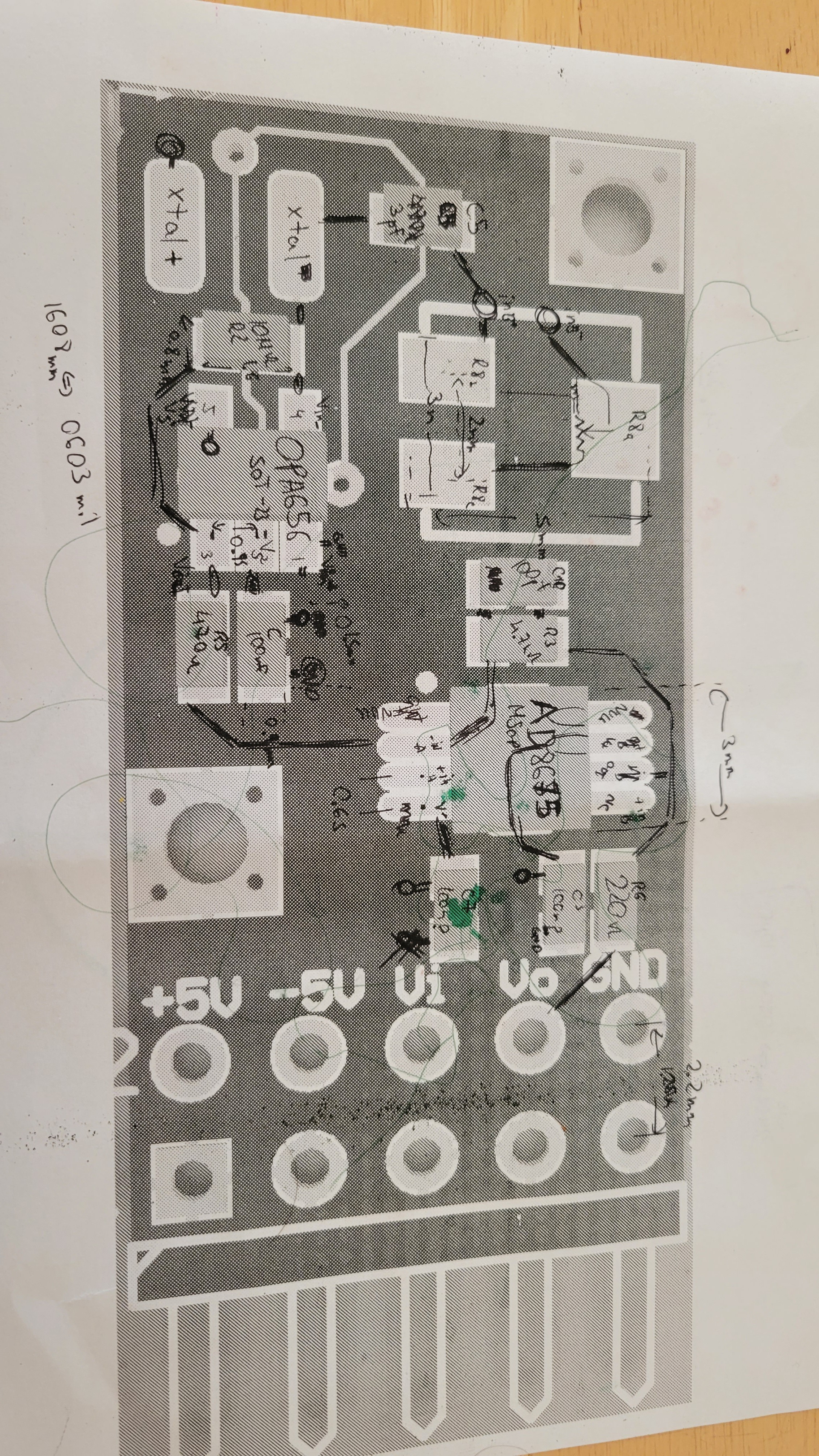
Still waiting to board and components to arive... meanwhile I thought it could be a good idea to 'reverse engineer' sensor board. Although you got the schematic it's unclear how and where to place each SMD component on PCB.
So I placed every resistor/capacitor from schematic: (an yeah.. I got kids ... 😂)
![]()
![]()
-
Mechanical fine movement
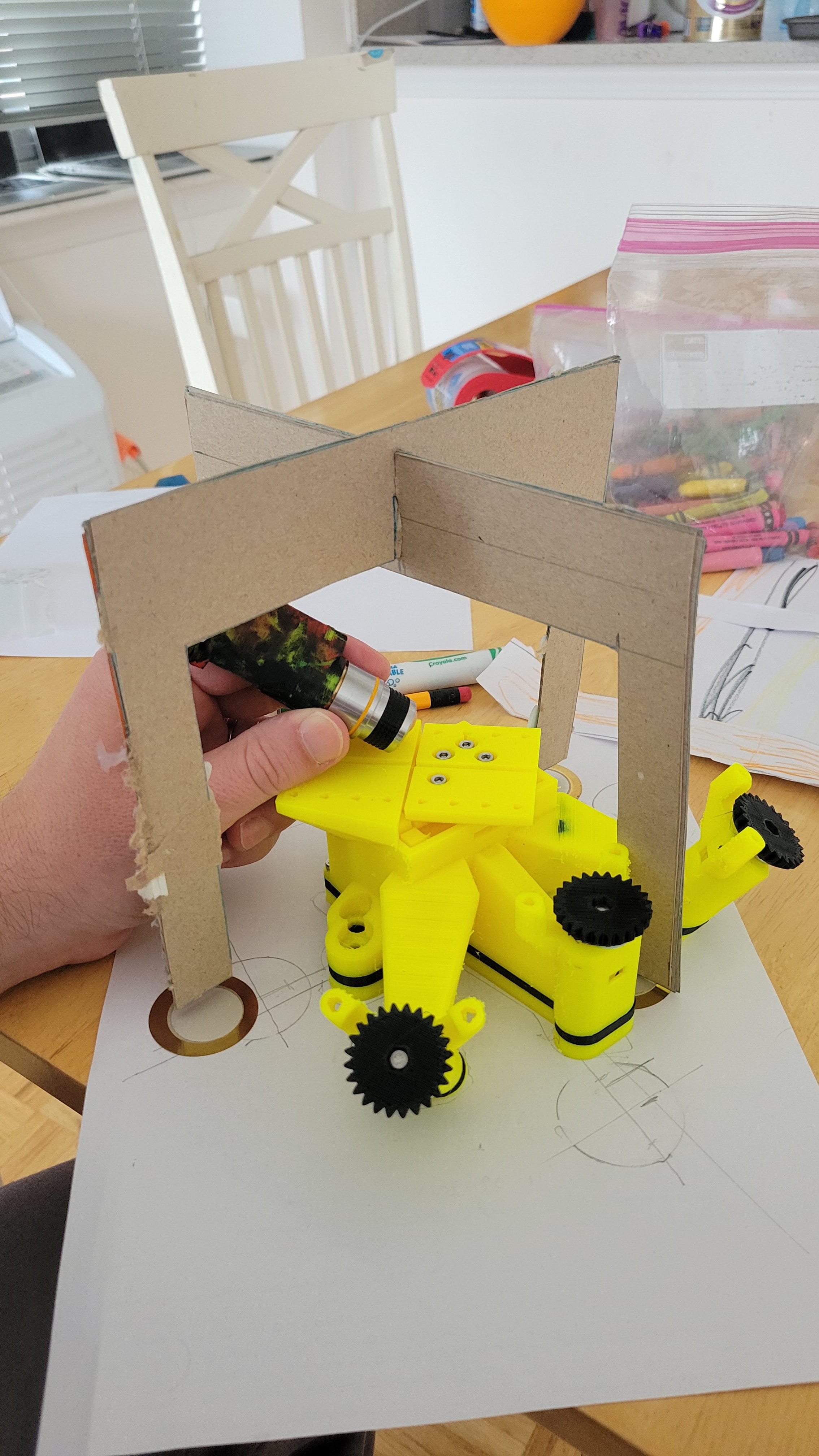
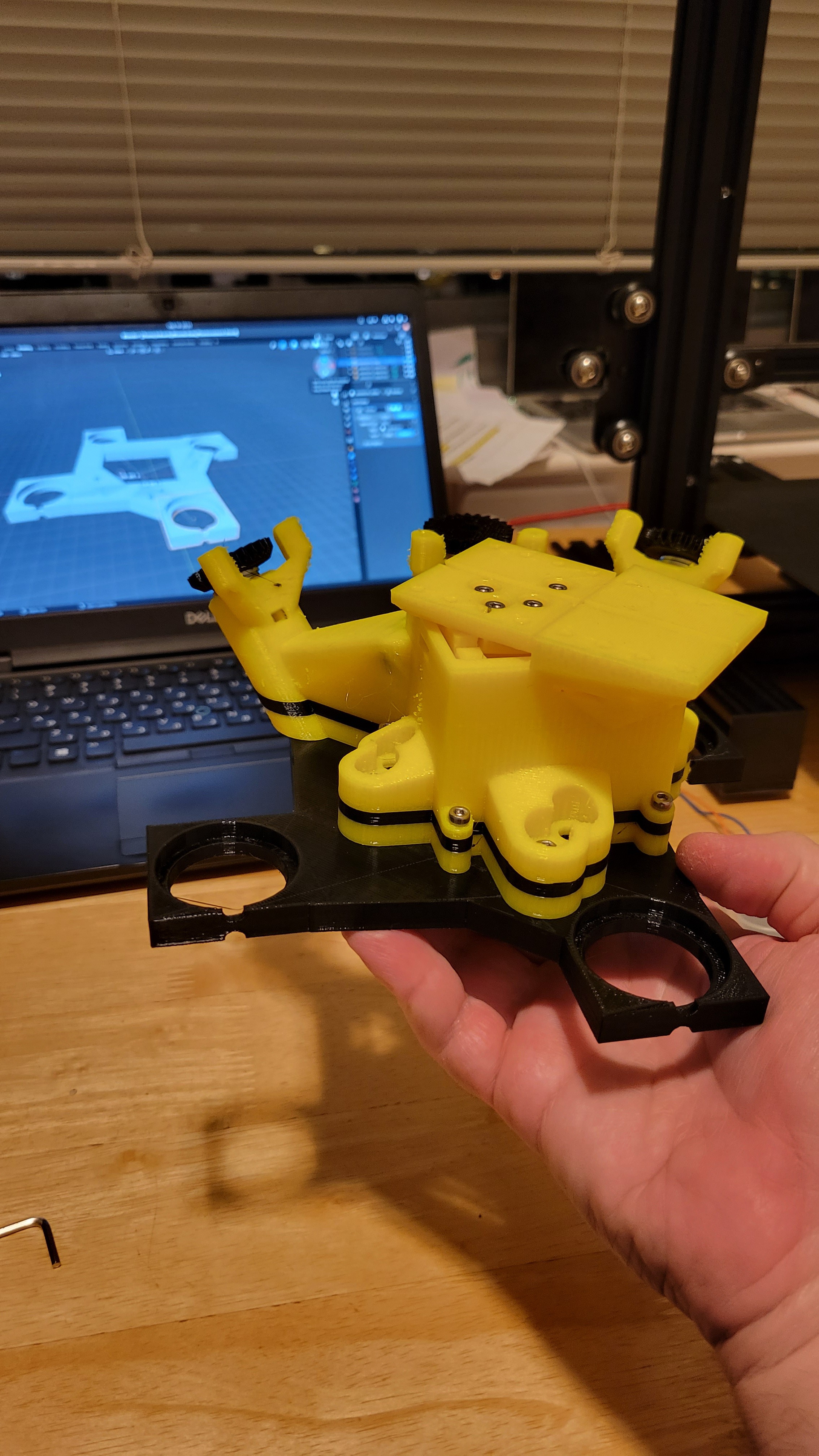
09/30/2023 at 19:37 • 0 commentsI know it looks silly but I started to prototype using some cardboard. This way I can get look and feel without hours of 3D printing.
![]()
And I already got some interesting insights. For example the spaces between the pillars can be greatly reduced without touching the moving stage base/enclosure.
It's only a POC made from few layers of dense cardboard but it's working and it amazing. It does moves a tiny actuator (a toothpick which is already broken) that can be seen only by microscope, since movement is so tiny.
![]()
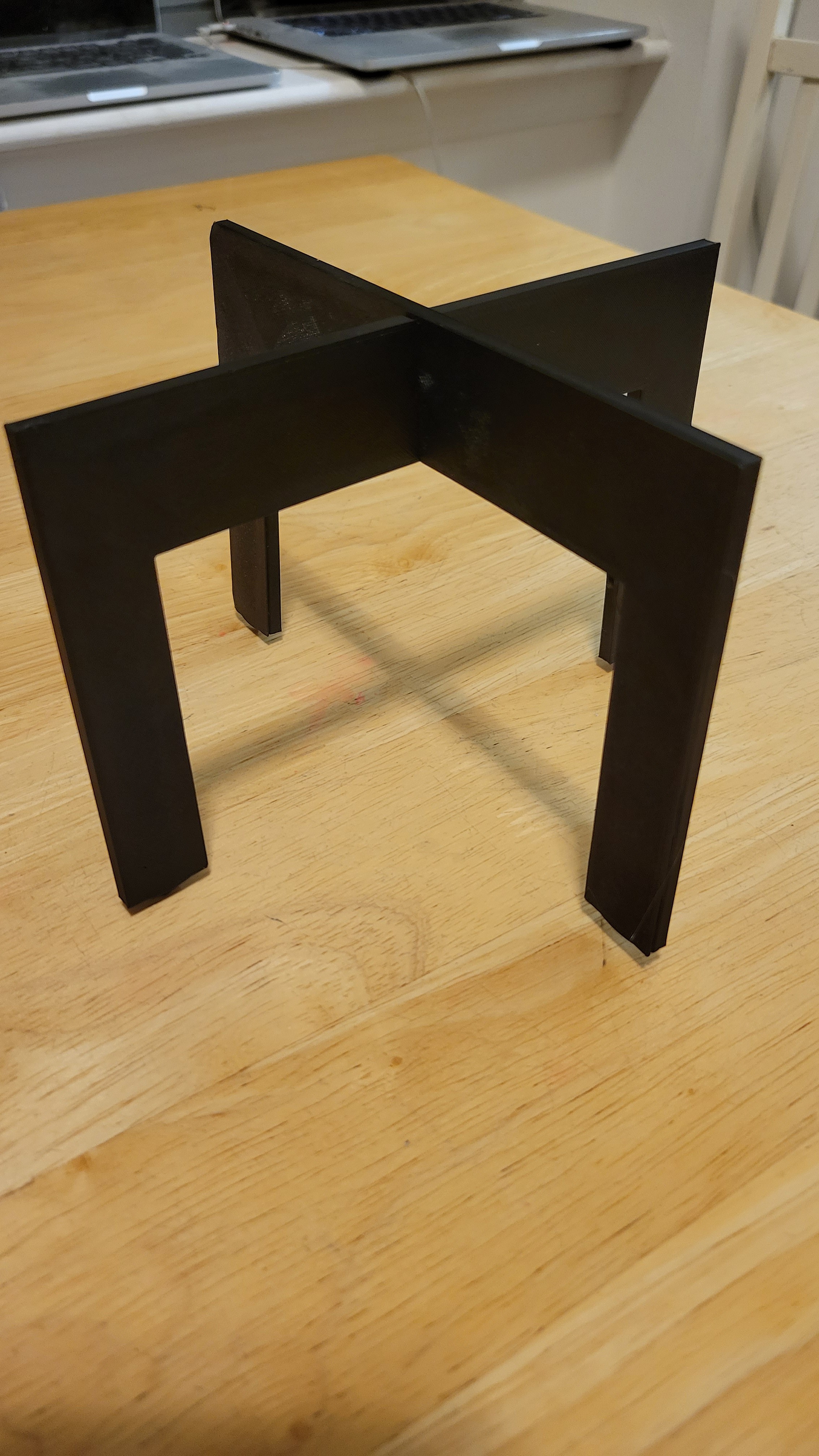
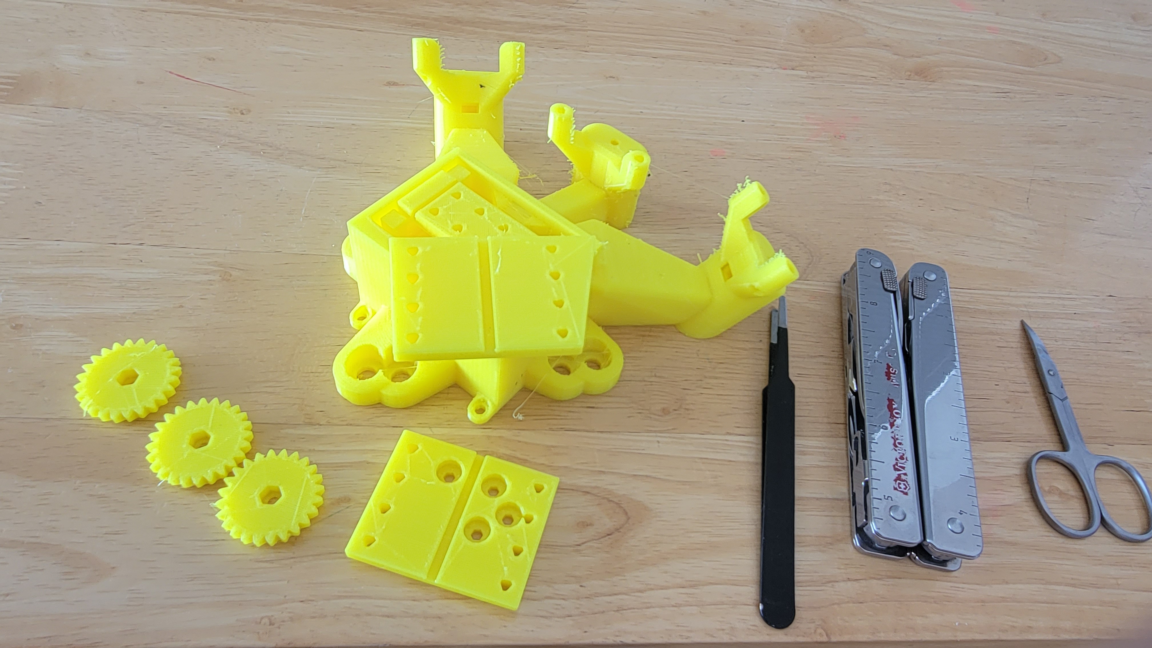
And now same thing 3D printed. Simple and does it's purpose. Now let's put four of this under the base.
![]()
Now I need four of them to hold 'the table' on which we will place nano scale needle.
![]()
TA-DA!! The nano probe holder
![]()
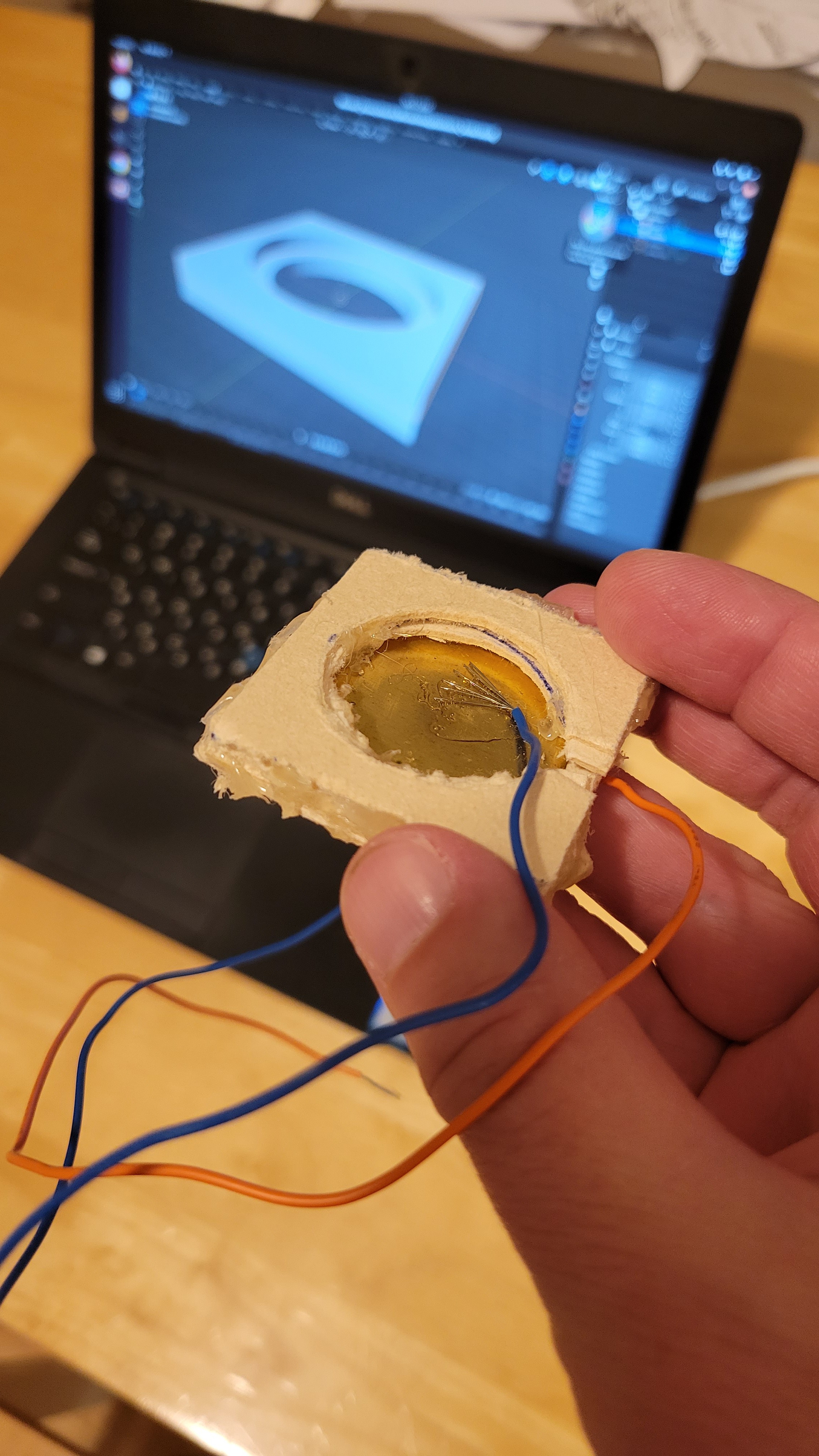
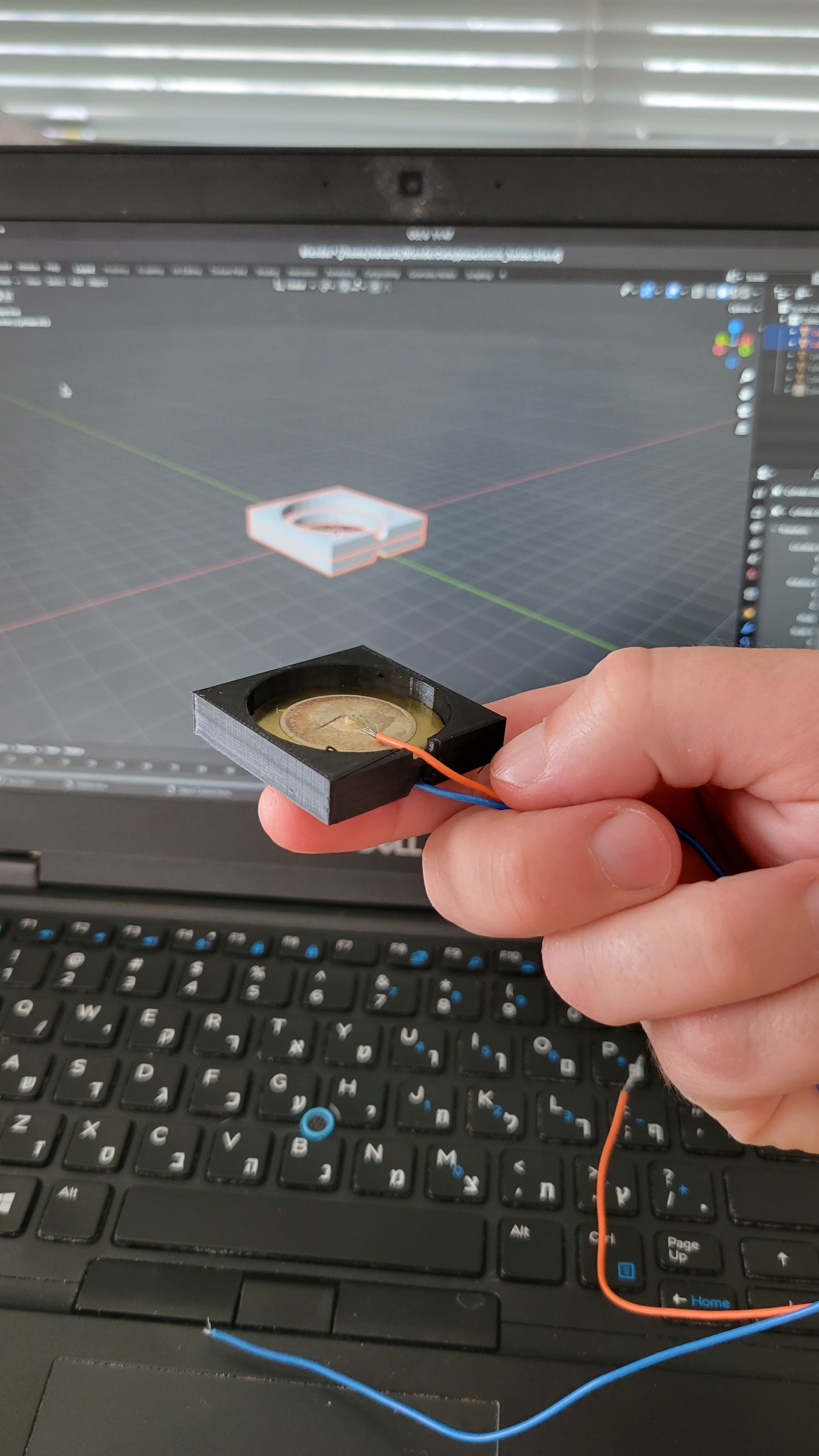
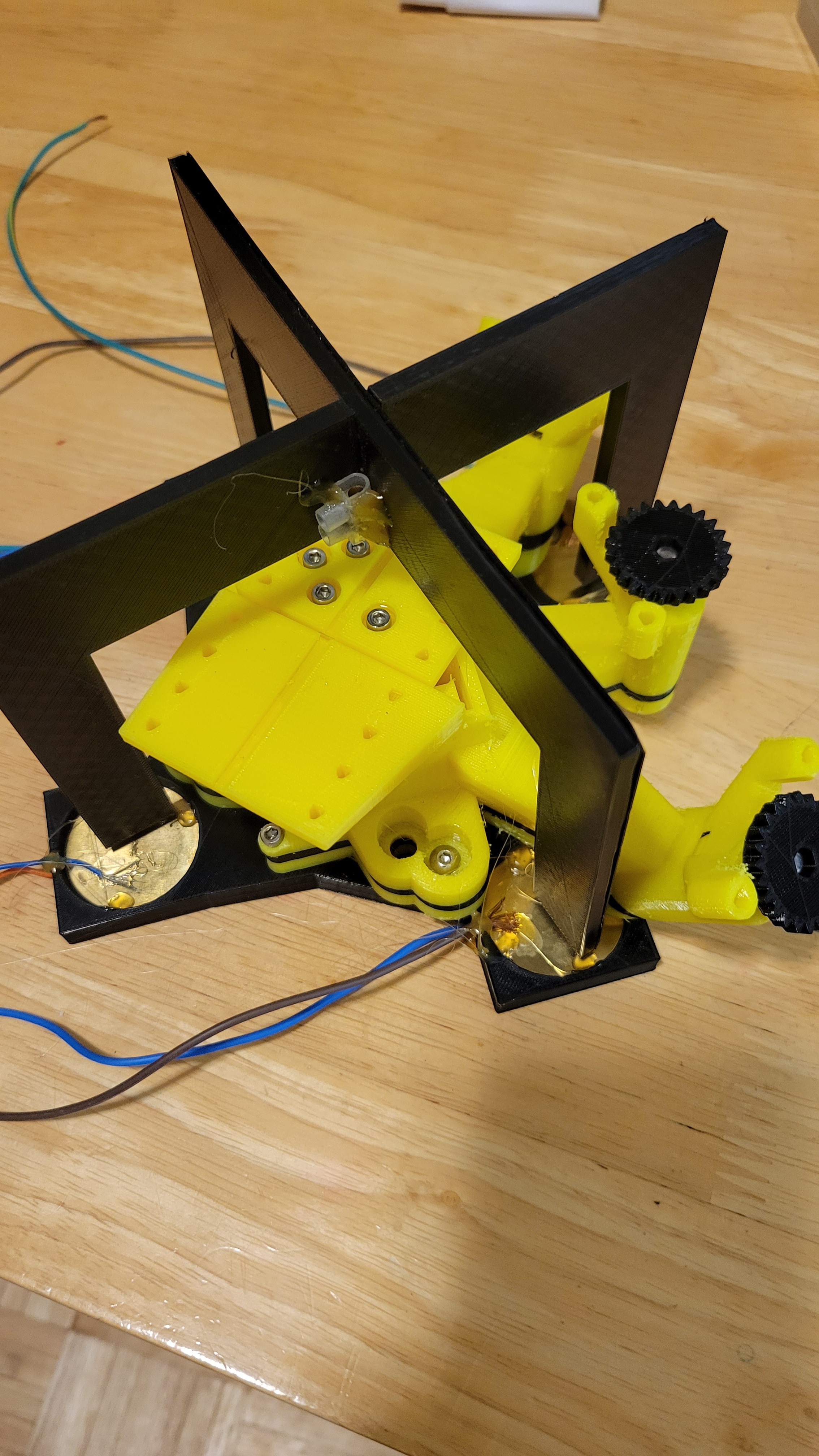
And now on pezo-mechanical bed
![]()
Actually this stage was done poorly as the glue was not silver glue. And hot gun glue that holds the pizo-electric devices is distributed not equally. I guess I will have to redo this stage later on as part of improvements.
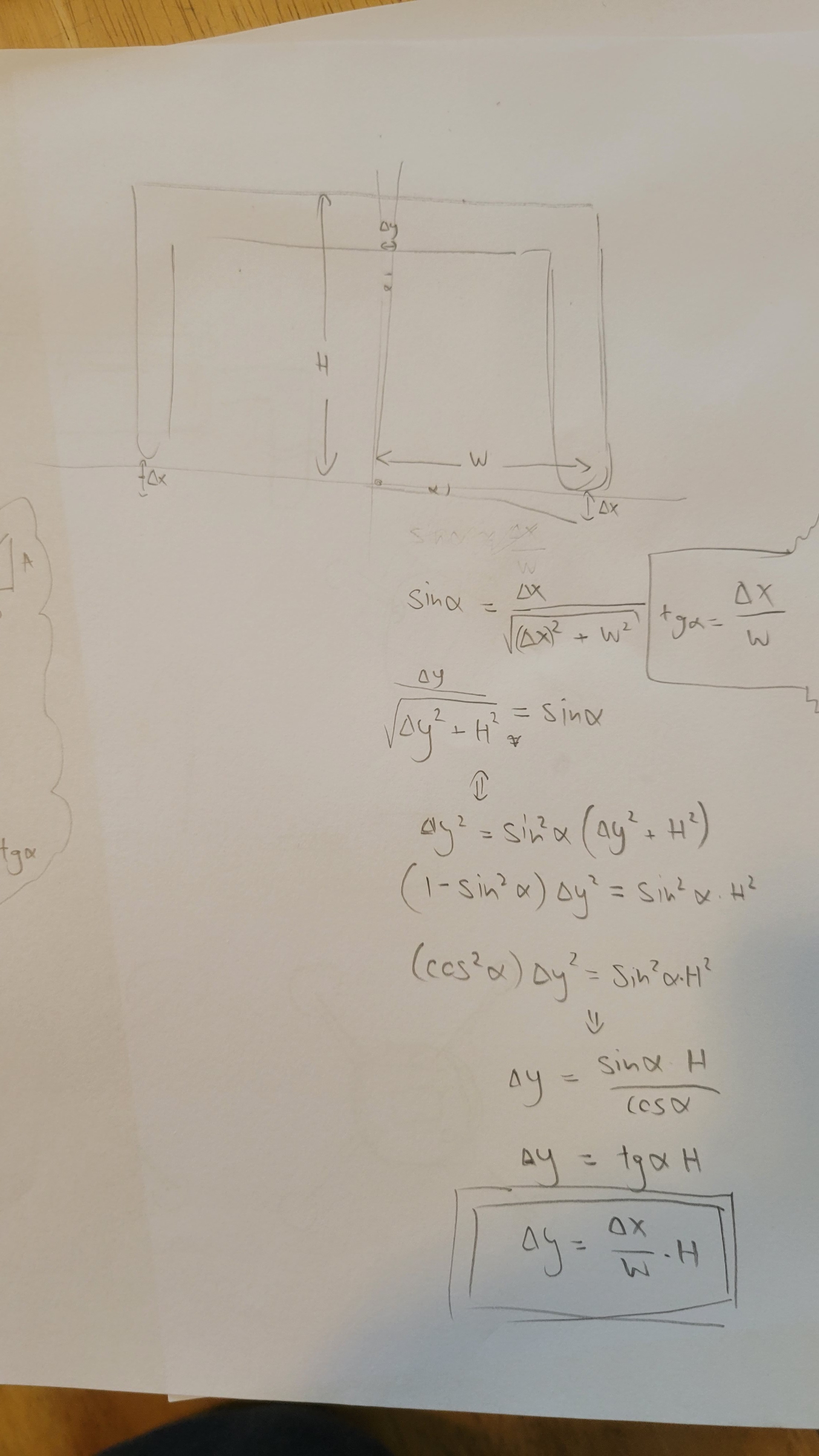
Some piece of math was missing. I mean if I move the piezoelectric up on ine side and down on the other side, how much nano probe will move?
![]()
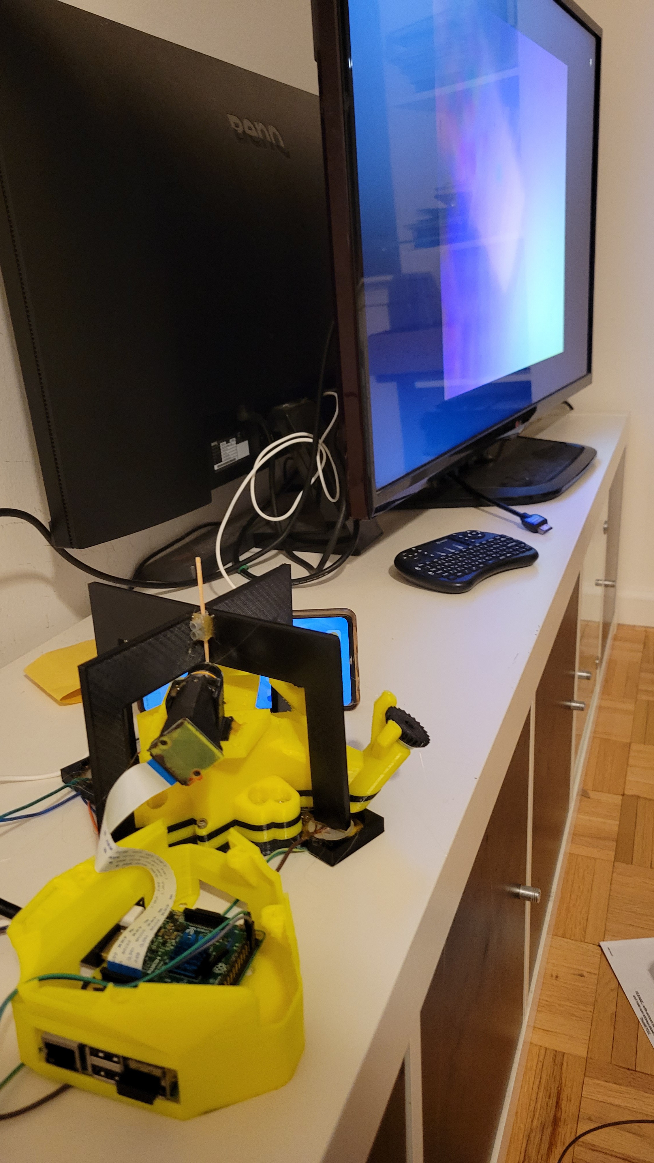
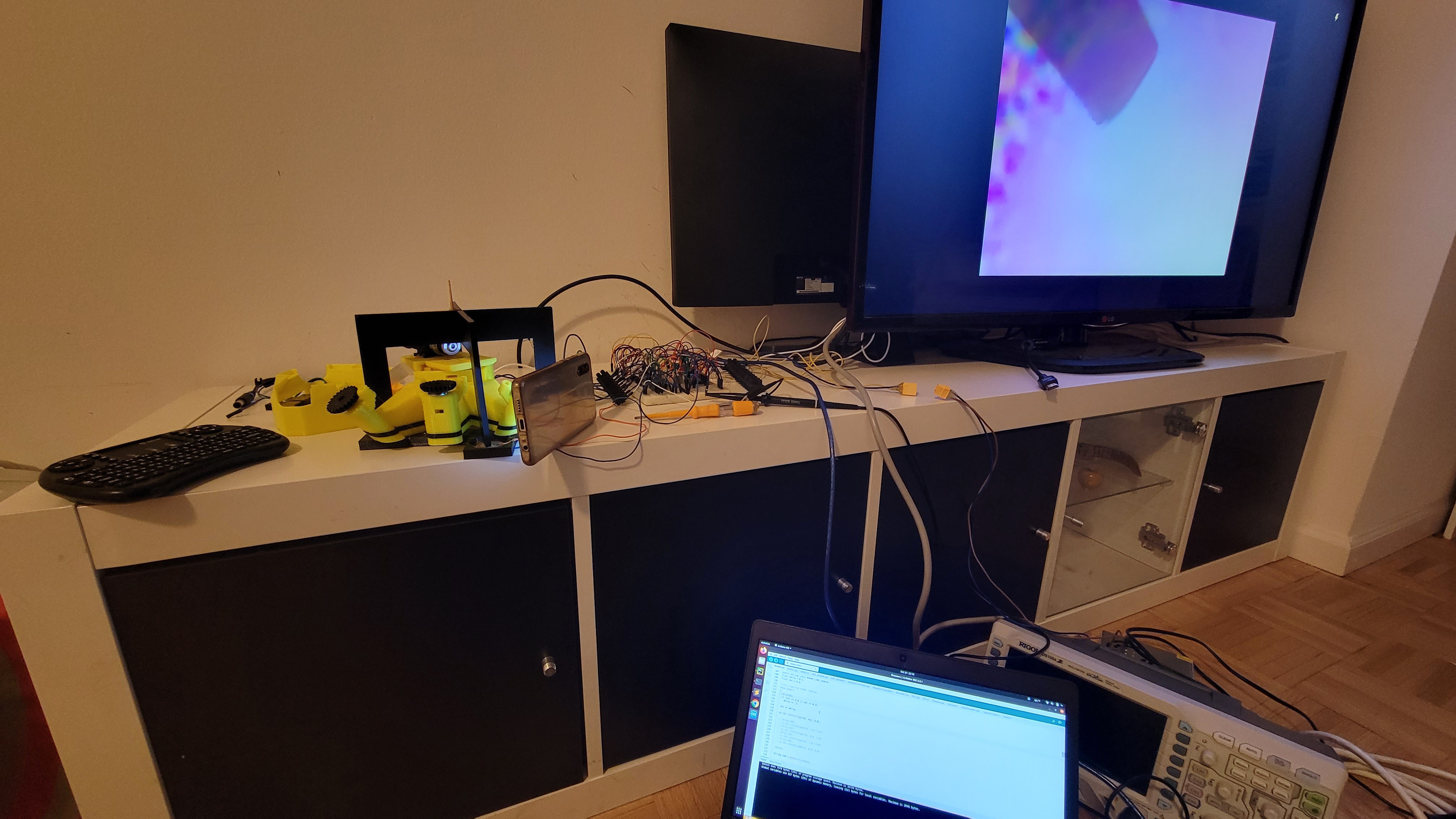
Now let's connect all together the RaspberryPi based microscope to see probe's height, fine movement mechanics and electronics.
![]()
(On the screen you can see magnified toothpick, tangsteen probe will come later)
Turn on the power and nothing 😞 it doesn't move...
More debugging with scope and reprogramming firmware to make move faster.
![]()
Finally I can see my toothpick moving up and down (run it with 1080p settings otherwise it's blurry) skip to 6th second.
I think I am done with this part! 😄 -
Coarse mechanical part
09/24/2023 at 23:32 • 0 commentsI was examining the mechanical parts given by some available opens sources. Most of them has only Z-axis manipulator. It's OK when you don't care where you land, for me it's crucial. So what I've saw used 'Adjustment Screw' to adjust the height of stage compared to the afm-probe. Plus the price tag was awbout 33$ for each. (and we need three of those).
So I decided to go on a different path. I am familiar with OpenFlexture project, it's an open source 3D DIY printed microscope. The provide both microscope and moving stage with submicron accuracy.
![]()
It has both the moving tray and a placeholder to put RaspberryPi based microscope.
We will need this microscope to accurately place the nano probe without bending/breaking it. (Also it has place to hold the LED) what else can I ask?
![]()
Now I have to figure out how to mount RaspberryPi based microscope/camera and I am done. Easy peasy, right?
-
Piezoelectric controller
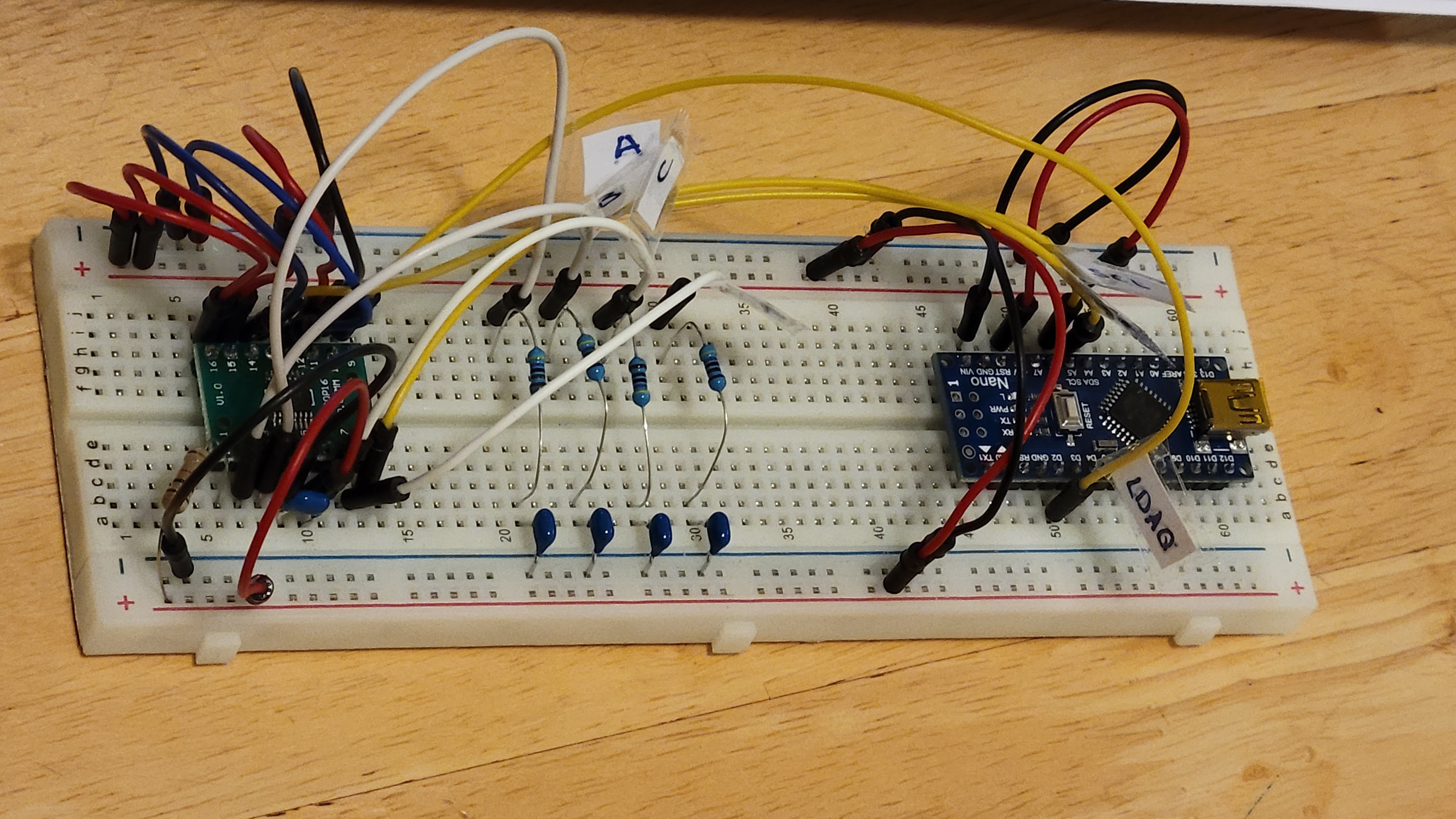
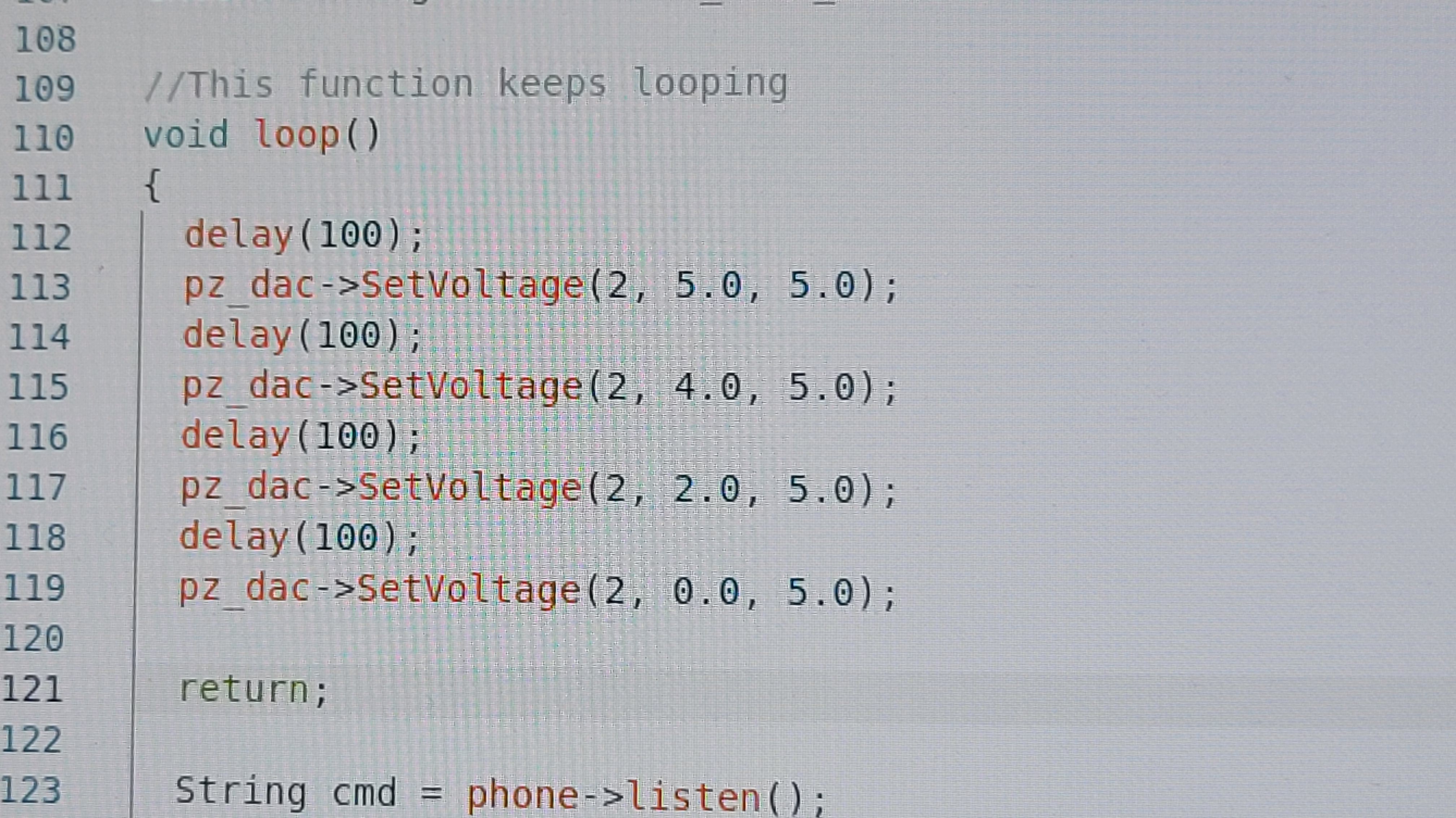
08/16/2023 at 04:12 • 0 commentsThis basically DAC which takes input from I2C. In my case this is Arduino nano as a master.
All other connections are the output and other configurations of the DAC chip. (Like reference,gain etc.)
![]()
The next step will be making Arduino and DAC talk over I2C and watch for change on A,B,C and D outputs.
Actually, this stage of I2C or Arduino to DAC went smoothly even beyond my expectations.
All I had to do is to disable input code (since we are not going to use same input) and change LDAC pin (since we are using nano) and vaila!
Here is simple code
![]()
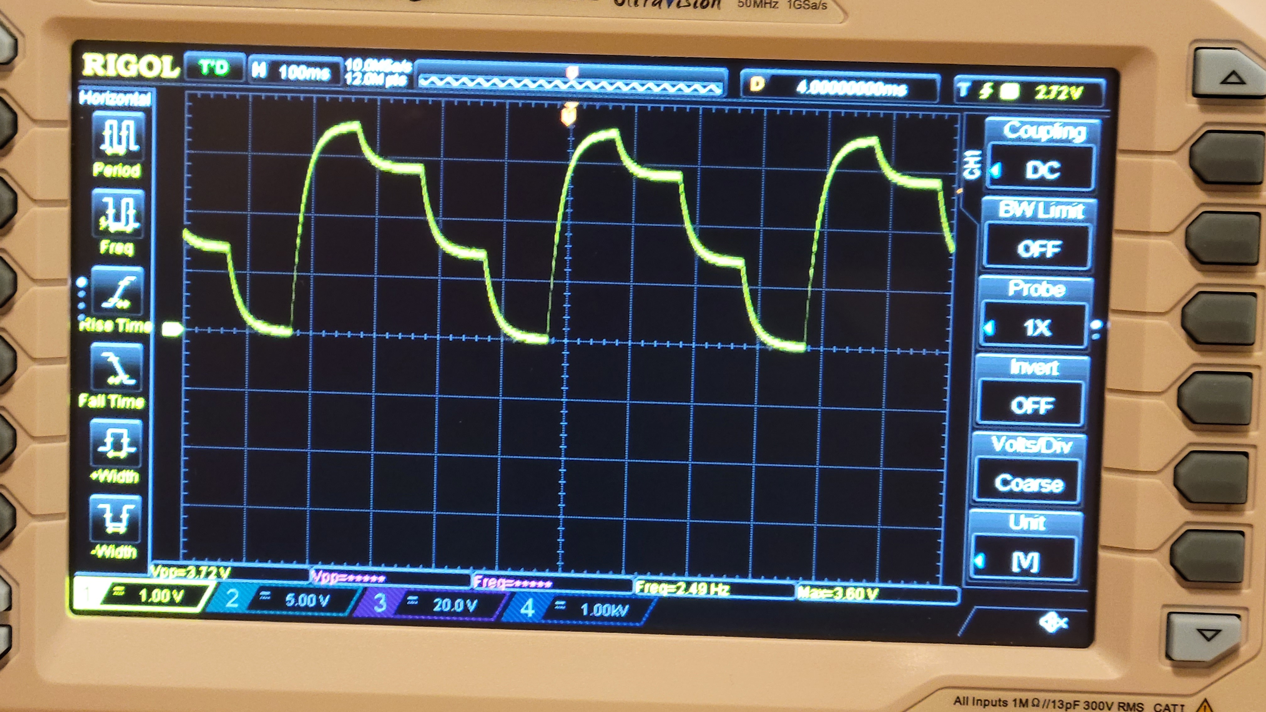
And the output:
![]()
The next step is to connect converter from 0-5v to (-12) - (+12)v but it's very technical and I don't expect any trouble with that.
As expected, connecting the op-amp was quite straightforward. Although I found bug in OpenAFM schematic (or my coping it), the gain of DAC should be connected to 5v so the total output should be from 0 to 2*Vref. Plus connecting the power supply we get this:
![]()
The output is not simetrical around 0v but this can be fixed by changing reference voltage for op-amp. Voltage is not fully rail-to-rail, but it can be fixed by taking bigger resistors as feedback. The problem is that I have that noise (the thick line) I believe it's due to the fact that I use bread board and not PCB with suggested layout.
I think I done with this part of the project
Atomic Force Microscope - from ground up
The aim of this project is to make high grade DIY or turnkey AFM.