Dan (a8ksh4)
-
Adding an internal USB hub
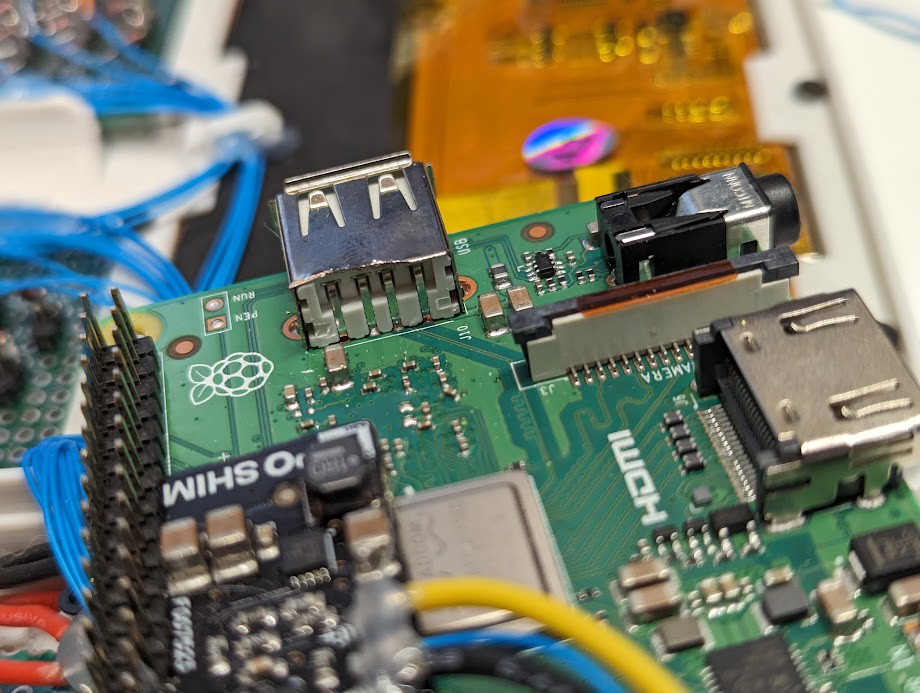
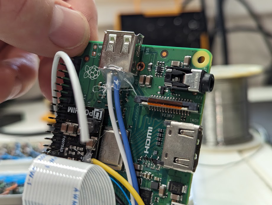
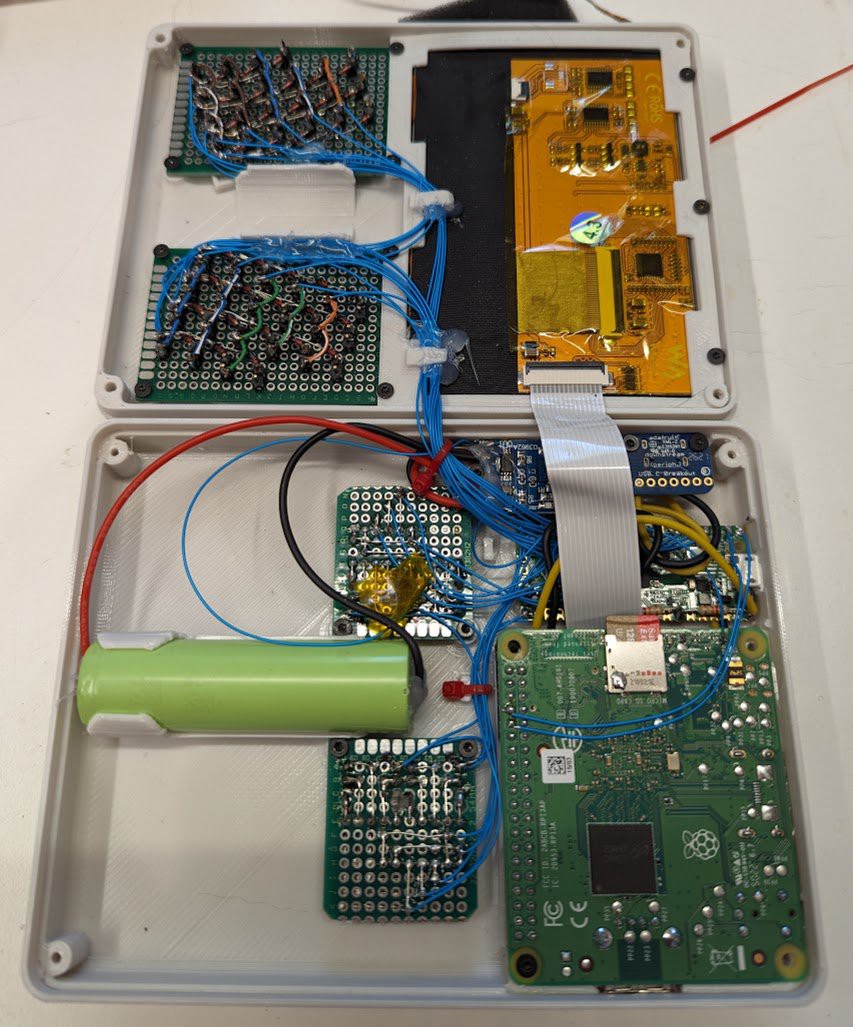
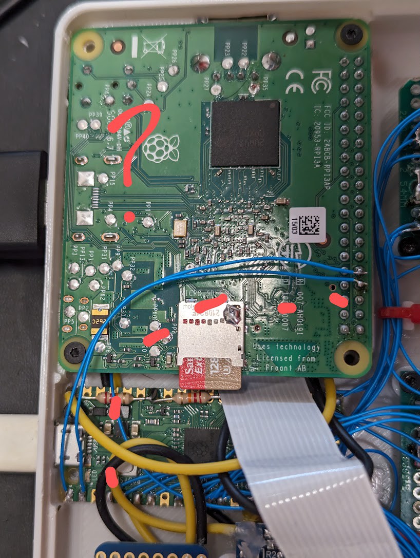
09/30/2023 at 17:35 • 0 commentsBecause I really just want this project to work so I can move forward, I gave up on the keyboard stuff over UART and hooked the Pi Pico up to USB. I still want to have the external USB port on the Pi 3a to work, so here's the process I used:
- Ripped the back off of the Pi 3a USB connector and cut the D+ and D- wires.
- Jumpered the Pi 3a usb v+, g, d+, d- wires over to the little USB hub.
- Ran wires from the hub to the Pi Pico USB d+ and d- test pads on the bottom
- Ran wires from the hub to the Pi 3a USB plug d+ and d- wires that were previously cut.
It works!!! 'lsusb' reports the hub and the Pico, and now I have /dev/ttyACM0 listed for serial communication with the Pico.
The essential thing I've found for running USB2.0 around like this is to keep the D+ and D- wires right next to each other for impedance matching - they act as a tuned transmission line and for anything but short distances, they need to be run together. The blue and white wires in the photos here are D+ and D-.

-
Fixed the uart stuff!
09/04/2023 at 05:12 • 0 commentsI posted previously about some display flickering, and I was having trouble getting the UART connection between the Pico and the Pi 3a working. With Ubuntu on the Pi 3, when I had the UART wires connected, the system would flash the display and not boot. I changed the OS to Raspberry Pi OS and it would boot normally, but I couldn't receive anything from the Pico. I kind of got frustrated with this and took a few weeks off from working on it.
I explored the idea of using I2C instead of UART, but I2C slave functionality isn't really supported by MicroPython. I talked to my guru a bit and troubleshooted by hooking up a USB UART thing to each device separately and found that the pi 3 was working normally but the Pico had no TX!
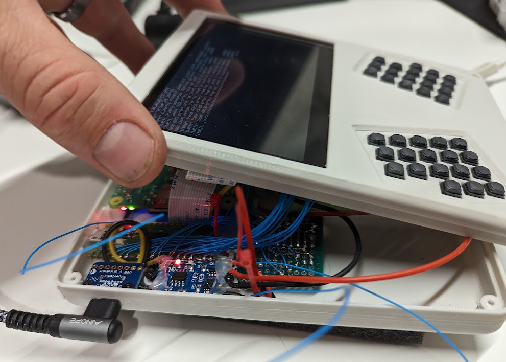
I was able to move the wires that were controlling the system power and pi LiPo shim and free up an alternate set of UART pins and everything is working now!! A basic keymap and it's printing some characters on the screen.
This is where I'm at now.
- I need to develop the keymap - The front keyboard is from a prev build, and I added the back 5-way switches because it sucks using only thumbs, so I can use the back switches for arrow keys, mouse wheel, and ctrl alt shift stuff, among other stuff that reduces load on the thumbs.
- clean up the keeb firmware to work better with this system - e.g. adding hold-shift support. I've only used oneshot shift on prev builds.
- Add some of the power stuff - flash display on low battery, auto shutdown, and full power off on battery limit.
- And playing with stuff! Gonna try the beeper matrix client and tweak some stuff for a nice tmux experience. I'm excited about trying carbonyl (fast chromium based terminal browser). And there's a bunch of other terminal stuff to play with.
-
Learned a thing about the pi pico vsys/vbus
07/26/2023 at 17:22 • 0 commentsI've been looking at documentation trying to figure out why uart doesn't work for me and got to looking at how VBUS and VSYS work on the Pi Pico. Looks like VBUS is directly connected to the usb V+, and VSYS is behind a diode. I believe this means that if you have battery connected to VSYS, it'll run the pico, but it won't power the usb port.
One concern I'd have with a usb plugged into the pico is that it might feed 5v back to the battery and over-charging it. For now, I've been using a usb cable to program the Pi Pico that has the positive wire disconnected.
An interesting thing is that the Pi Pico has VSYS connected to ADC 3 (gpio 29) with a by-3 voltage division. I had soldered on a couple of external resistors to get a voltage on ADC2 (gpio 28), but it seems this is unnecessary!
>>> vsys = ADC(29)
>>> vbat = ADC(28)
>>> vsys.read_u16() * 3 * 3.3 / 65535
4.042179
>>> vbat.read_u16() * 2 * 3.3 / 65535
4.124358
I'm still having trouble with the UART connection between the Pi Pico and the Pi 3A+. Will update when I get that working...
-
Assembly about done, small glitches to sort out
07/25/2023 at 01:07 • 0 commentsThe last bits of soldering I needed to do today were:
- Hook up power to the pi pico
- Solder on a couple resistors for the voltage divider to the ADC pin
- Solder the enable wires for the lipo shim and the master power switch to the pico.
- Solder the uart wires between the pi 3 and the pi pico
This mostly workd great. I was able to use the pico serial console to switch the pi 3 on and off in software and measure the battery voltage. Also I re-tested all of the buttons and stuff to make sure I didn't break any connections.
However, I had screen flickering when the pi 3 was on... turns out that something to do with the uart pins having wires on them is causing a prob. I'm not sure what yet... I tried with the dsi display and hdmi and same prob on both.
-
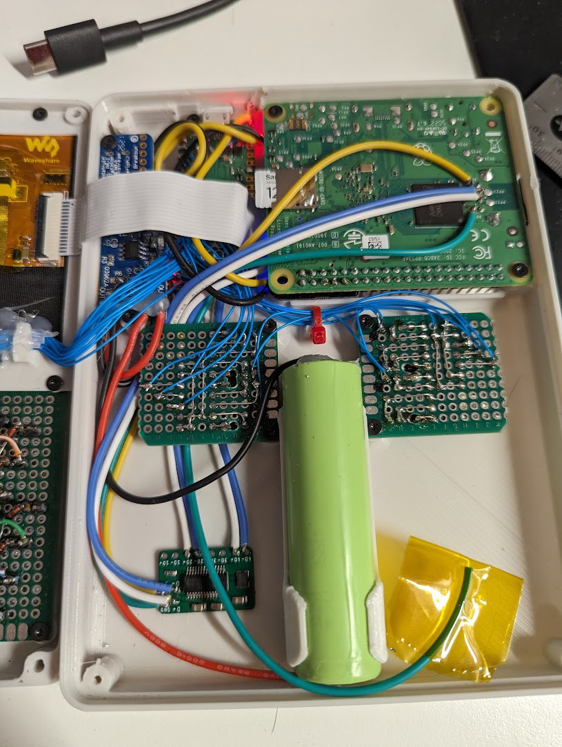
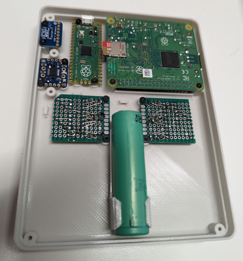
Final assembly in progress
07/22/2023 at 22:16 • 0 commentsI haven't tried to cram the whole thing shut yet, but I'll have to soon. The keyboard/input and power stuff is all crammed in there together with the ribbon cable for the display. It's been getting some selective hot-glue to keep things organized. I turned it on with battery only and it shut off after a min. I'm not sure yet if it was more dead than I thought, maybe I accidentally bumped the power button, or ???. Anyway, I plugged in usb power to charge it and turned it back on to make sure the screen was good and run updates. That was all good.
Next steps are:
- Solder power wires to the pi pico
- Solder two resistors to the pico for to connect the battery to the analog input for checking voltage
- Wire the pi pico to the pi 3 for data comms... I need to read a little about which pins I want to use.
Regarding data between the pi pico and the pi 3 - previously I'd just plugged it in with usb and used usb serial for all the data passed from the pico to the big pi, but I'm going to try using the gpio pins this time... not sure if I'll use spi, cc, or uart. I need to read a little about which of them I can set up the pi3 to use with interrupts on communication so I don't have the cpu spinning on it checking.
-
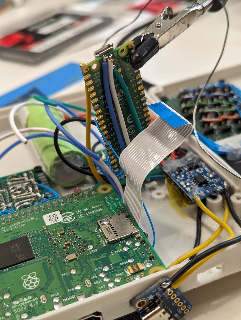
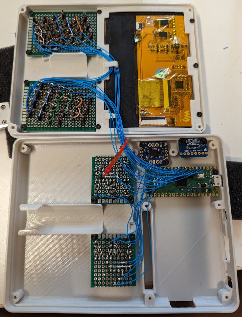
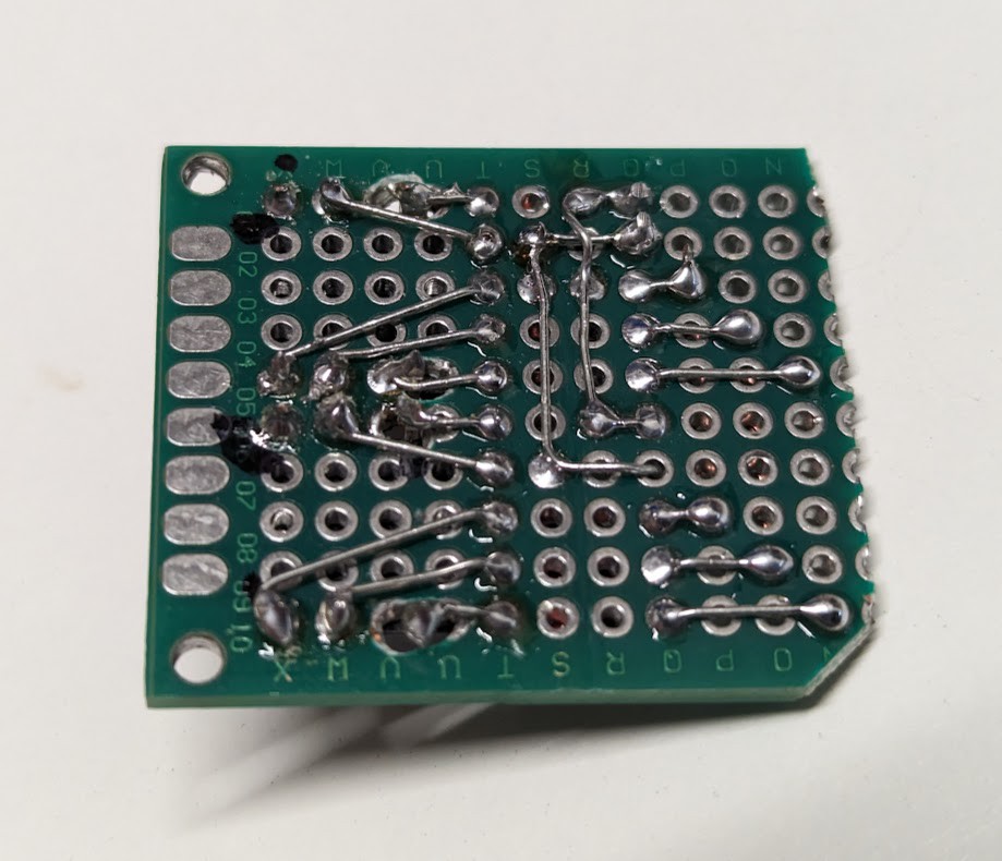
Input and power wired mostly!
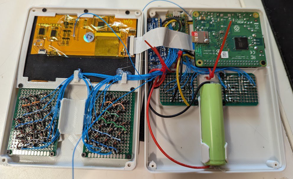
07/22/2023 at 01:06 • 0 commentsSolid progress. I re-made the back 5-way switches with diodes the other way around. My first draft will get used in some other project another time. And all input devices are wired up and working now!
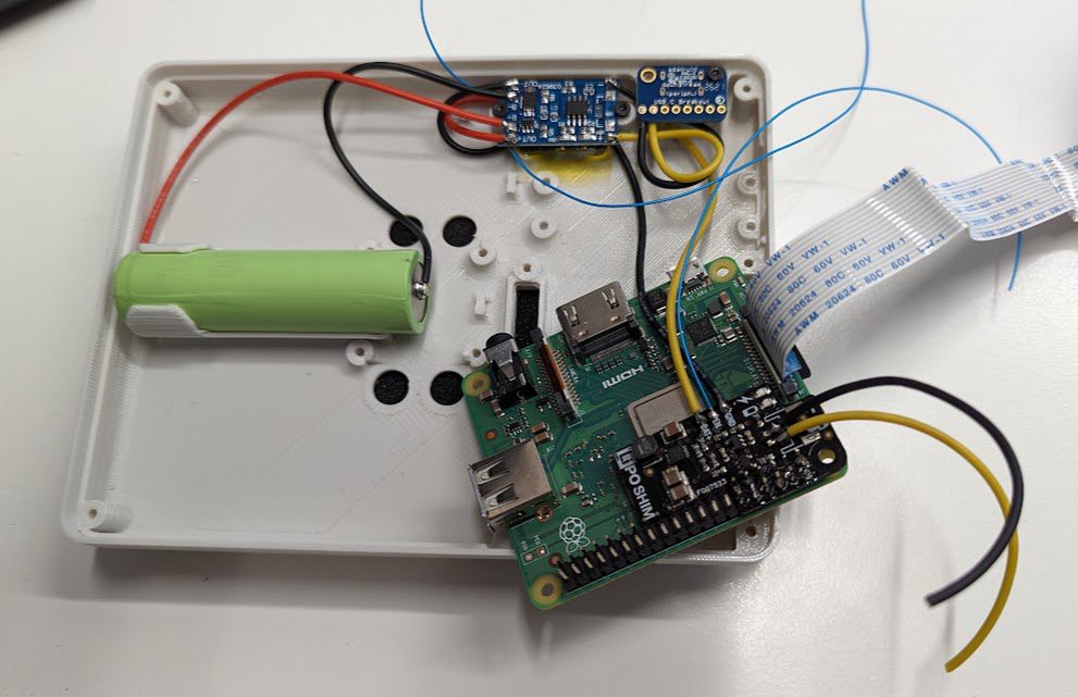
And the power stuff is all soldered up now:
- USB to charge board is black and yellow.
- Battery to charge board, and charge board to the main power switch are black and red.
- Power switch to the pimoroni lipo boost shim is black and yellow,
- And I left a black and yellow pair hanging off the shim to power the pi pico at un-boosted lopo voltage.
- The fine blue wires are:
- v+ from the switch directly to a resistor bridge to the pico analog pin for battery monitoring.
- off pin from the switch to the pico to turn power off completely to everything
- enable pin from the lipo shim so the pico can cut power to the pi 3a+ board.
I would be doing final assembly but I goofed up the last print.. So I'll hopefully put it all together and not have unexpected issues with fit this weekend!
Aaaand a note about soldering to 18650 cells - I don't recommend it, but if you do, use flux and a hot iron. Get a blob of solder on each end of the cell, clean up the flux with alcohol, and let it cool. Tin your wires. Then go back and solder the wires into the blobs, working fast so you don't put much heat into the cell. It's better to spot weld or maybe use a battery holder.
And on this theme of doing responsible things, I will go back and add an axial fuse to my battery lead. It's a good idea for safety.
-
Wiring - two steps forward, one step backward
07/19/2023 at 01:08 • 0 commentsI just finished wiring up the keyboard and 5-way switches and wrote a bit of micropython code to test them. None of the 5-way switches are working, but all of the front keyboard buttons seem to work! I'm not sure, but I must have wired the diodes backward on the 5-way switches... Maybe I can fix this in software? I might need to re-make them.
Here's the test code I'm using to matrix scan rows/cols and print which buttons are pressed on the console
from machine import ADC, Pin import time ROWS = (2, 3, 4, 5, 17, 16) COLS = (6, 7, 8, 9, 10, 11, 12, 13, 14, 15) cols = [Pin(n, Pin.OUT, value=0) for n in COLS] rows = [Pin(n, Pin.IN, Pin.PULL_DOWN) for n in ROWS] all_buttons = [(c, r) for r in rows for c in cols] def getValues(): out = [] for n, (c, r) in enumerate(all_buttons): c.on() if r.value(): out.append(n) c.off() return out while True: print(getValues()) time.sleep(1) -
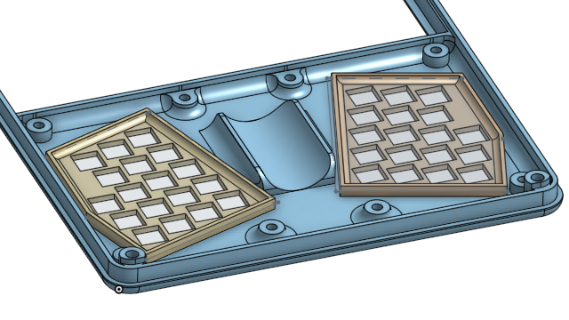
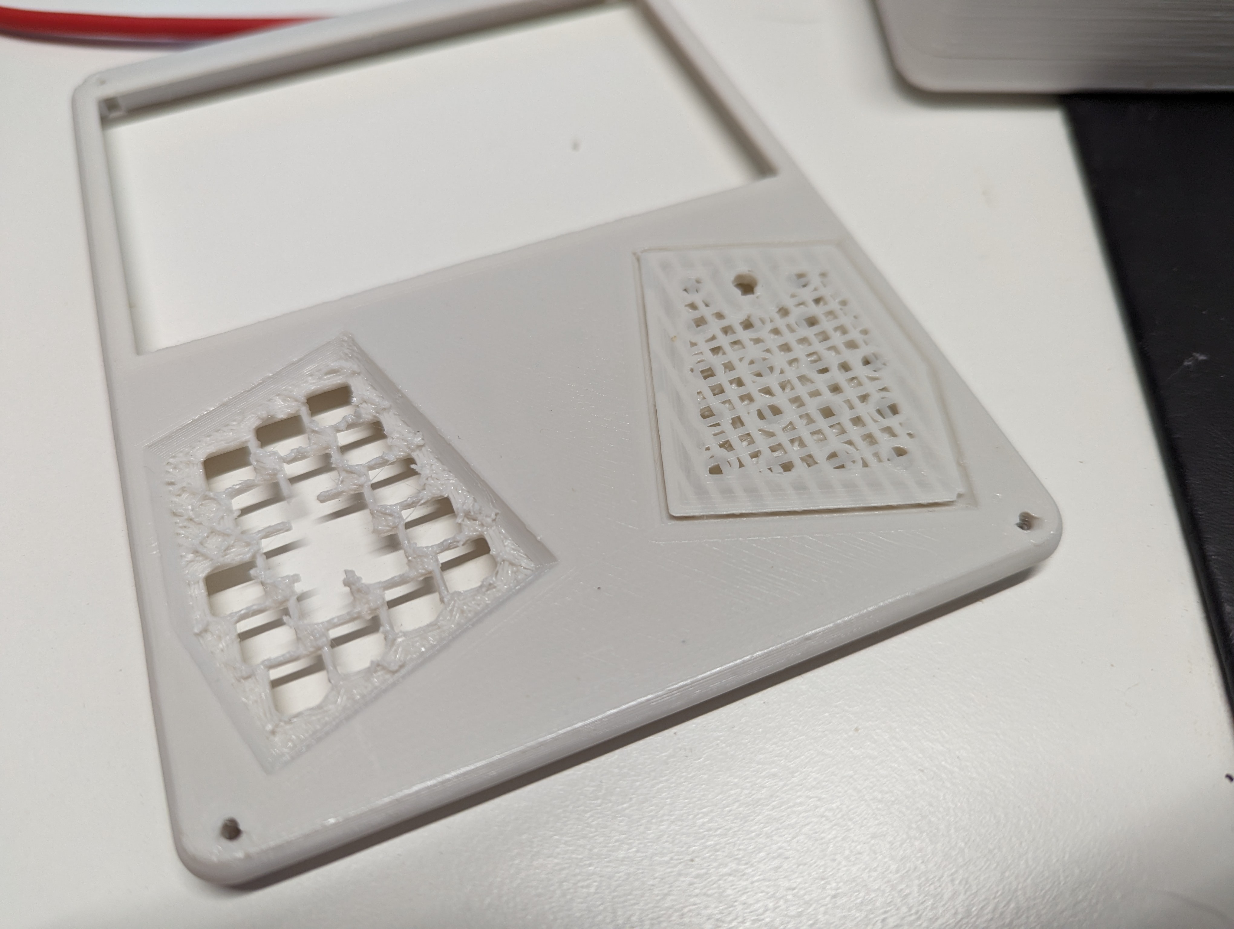
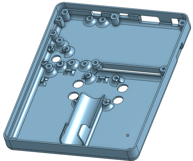
Iterative progress. Refining the model for the case.
07/15/2023 at 19:50 • 0 commentsI want to finish the design for the case before I solder everything up, so that's what I'm doing this morning. I've been having a lot of trouble removing supports from the intricate part of the front panel that fits between the keyboard keys, so I've opted to split these plates out into separate parts, hoping that's a little more clean and simple.
It can be tricky going back and making changes like this to a complicated model. I try to make simple changes to the existing drawings and extrusions, and then add blocks of additional changes to that.... hard to explain. Just have to keep things organized or the cad model can get unmaintainable very quickly.
Aside from that, it's gotten a few small updates:
- Added screw in the four corners of the case, which involved shifting the raspberry pi up a little, but that was good because it put the micro USB port in a better position.
- Added zip tie points for wire routing
- Added wire clips on the panel that holds the display in place.
I just did a quick assembly of the last set of prints and it's too thin to fit the battery. I'm not sure how that happened, but I need to add 2mm depth to the front panel to make it work. Getting closer anyway! Another print shortly.
-
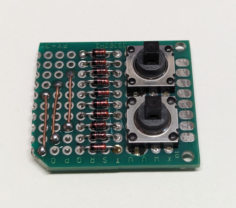
Soldering the 5-way Switches
07/05/2023 at 17:32 • 0 commentsThe front keyboard is a 10x4 matrix, so I'm soldering the four 5-way switches up like an extra two rows on the keyboard for a 10x6 matrix when done.
-
Power and Pi Pico Musings
07/04/2023 at 05:04 • 0 commentsI'm taking some inspiration from the Beepberry with an always-on, or primarily-on, Pi Pico that is in charge of power-up and shutdown of the Raspberry Pi 3A+. And I'm making some stuff up as it makes sense for this particular adventure:
- Power Control and conservation:
- The power button on the back is the hard-on and hard-off button.
- The pico will run at battery voltage and the pi has the lipo shim to boost to 5v. This gives independent control of the pico and pi.
- When I push the power button, the pico will get power. And I can push it to make sure stuff is off if the system hangs. This is a complaint I have with the pimeroni on off shim - it won't turn the system off if it is hung and the OS doesn't toggle a gpio pin at the end of shut-down.
- The pico will boot and then signal the Lipo shim on the Pi to turn it on.
- The pico can signal shutdown to the pi and power it off.
- The pico can toggle the "off" pin of the power switch to completely power down the computer.
- Activity Monitoring:
- All of the user input aside from the touch screen is through the pi pico, so it can keep an activity timer.
- The pico can signal to dim the display or turn off it's backlight after configured periods of inactivity.
- The pico can signal to flicker the backlight if the battery gets low.
- The pico can use an analog pin and resistor voltage divider to track the battery level.
- Power Control and conservation:
Thumb Term
Battery powered Linux-terminal handheld with front and rear inputs, 4.3" DSI LCD, a Pi 3A+, and GPIO breakout. WIP.