Petar Crnjak
-
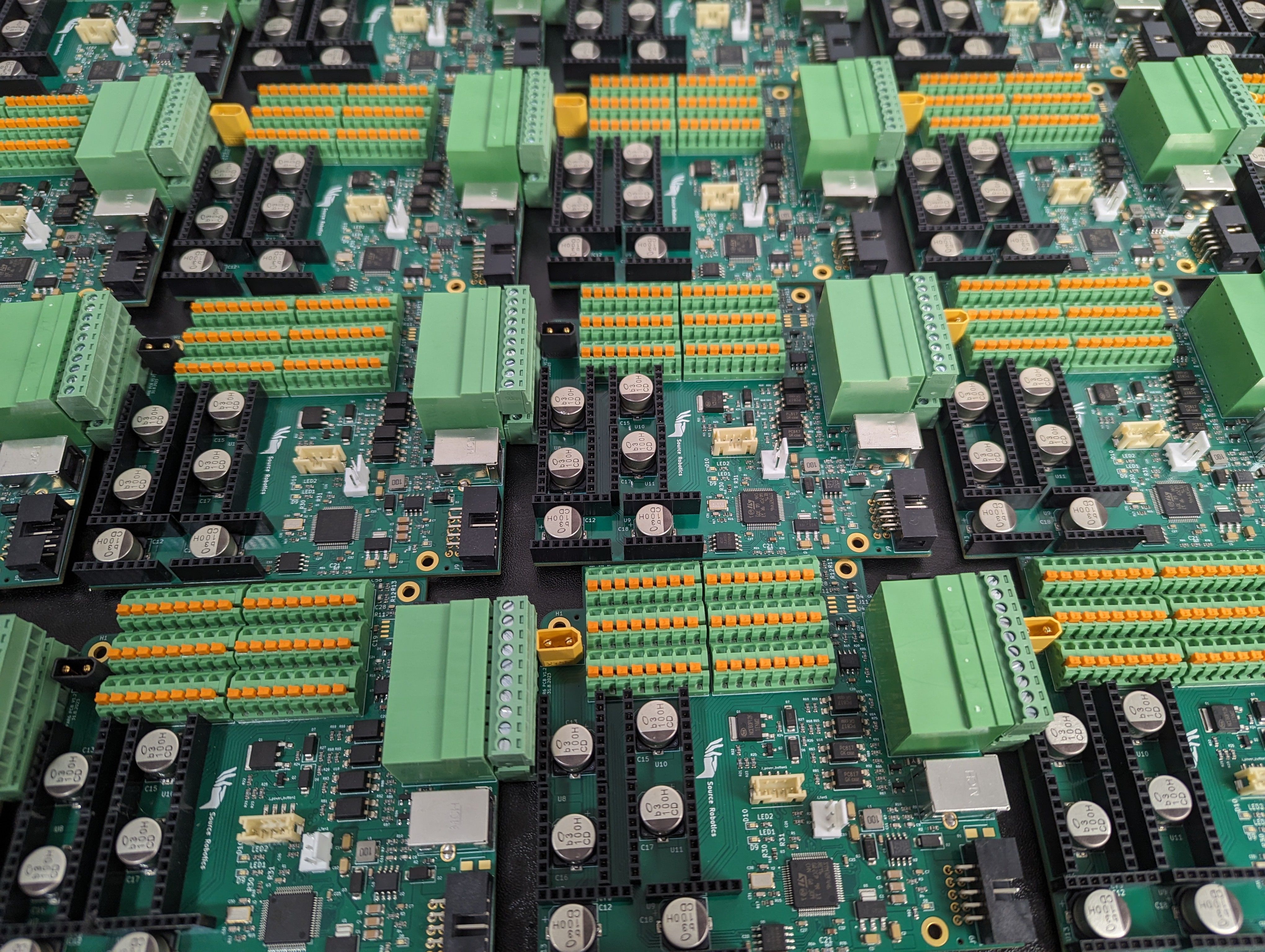
Beta batch of PAROL6 PCBS
10/09/2023 at 14:19 • 0 commentsIf you are interested in the beta batch of PCBS sign up here:
https://forms.gle/sZqHVLPoMJxuVAyJ9If you are interested in buying PAROL6 as a kit, fully assembled robot, or just a gripper sign up here:
https://forms.gle/XkSvStwnQxw1f8xL8 -
30 more PAROL6 robots coming soon!
09/28/2023 at 10:57 • 0 comments![]()
-
Robot testing code!
09/27/2023 at 07:32 • 0 commentsTo test PAROL6 control board connection to your robot you can use stock software or use testing software. Testing software is more safe and interactive for users. It can be found at github. Once you flash your PAROL6 control board testing will start.
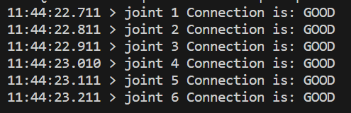
Stepper drivers test
The code will try to communicate with stepper drivers. Output1 and Output will go from high to low every 1s and LED1 and LED2 will flasg. If everything is okay you will get output like this on serial:
![]()
If the stepper driver is faulty or not connected you will get:
![]()
If stepper drivers are good your stepper motors should spin at a low speed using moderate current of 200-300 mA.
Flash memory test
In the serial terminal write # FLASH and press enter. You should get an output like this for a successful test.
![]()
LIMIT test
In serial terminal write # LIMIT and press enter. You should get a output like this if you activate the switch.
![]()
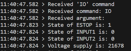
IO
In serial terminal write # IO and press enter. You should get an output like this:
![]()
If you change the state of ESTOP, INPUT1 or INPUT2 you will see states changing. You will also be able to see the voltage of your power supply in mV!
-
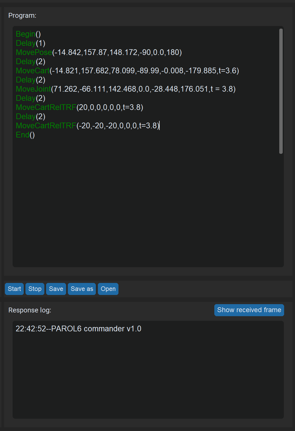
Trajectory follow and script language RBTscript
09/16/2023 at 21:01 • 0 commentsPAROL6 commander software allows you to write simple robot arm scripts. The scripting language is called RBTscript. It allows you to move the robot in joint space or cartesian space, use delay functions, control outputs, grippers, read inputs, and much more!
![]()
How are trajectories tracked?
Once the program starts it needs to generate and track commanded trajectories.
There are 2 ways we can command robots' trajectory here:
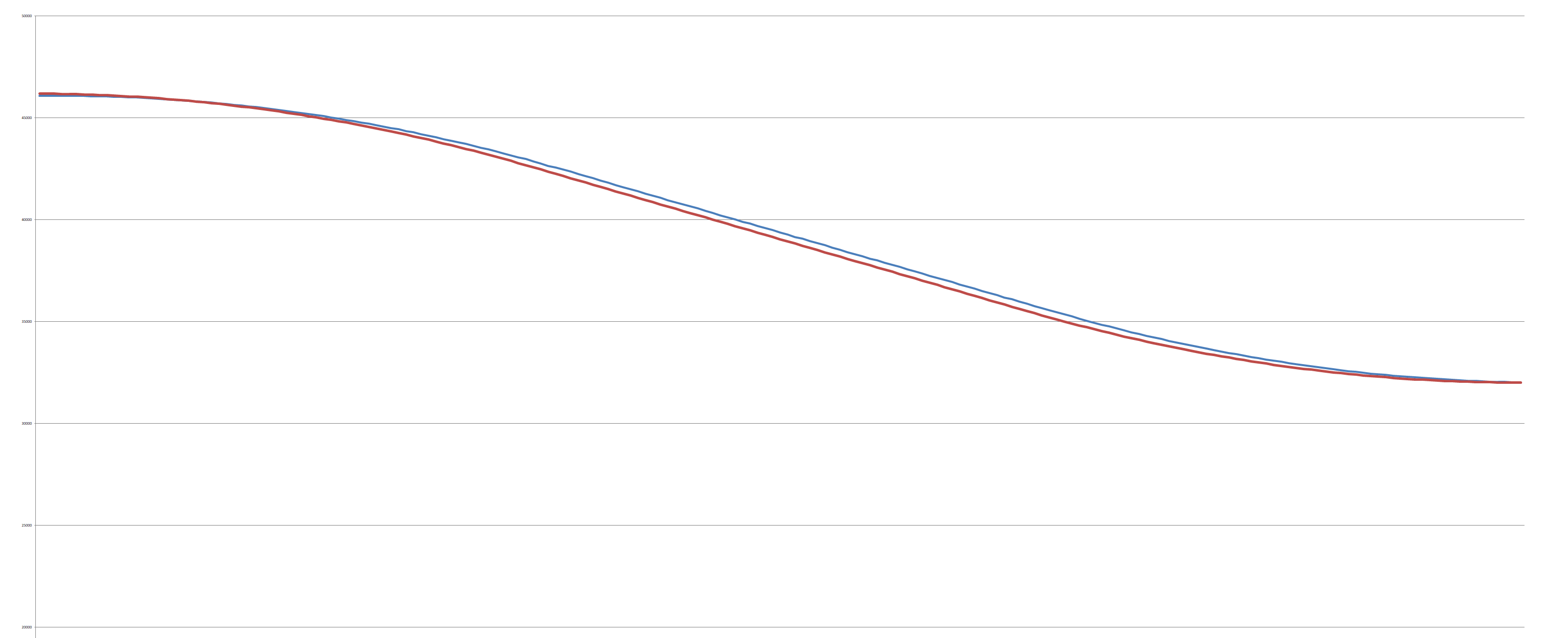
For example, we want joint 6 to move from 260 deg to 180 degrees. We want to follow trap velocity profile and get to 260 position in 2 seconds. We generated speed and position curves.
Now if we command only the speed curve robot will follow it perfectly but if the move is too long or too fast it will miss the demanded position. Why? We are sending commands every 10 ms. but it is not always exactly 10 ms since pc is not a real-time machine that time fluctuates. another thing is that steppers execute some really small speed moves from the beginning and the ends of the speed curve. Because of that position is missed usually. How to compensate for that? Use position curve. Use your current position and commanded position and calculate how fast you need to go. After that take that speed and add commanded speed and average that.![]()
![]()
-
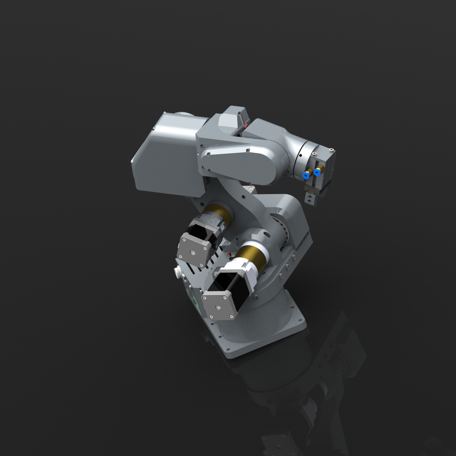
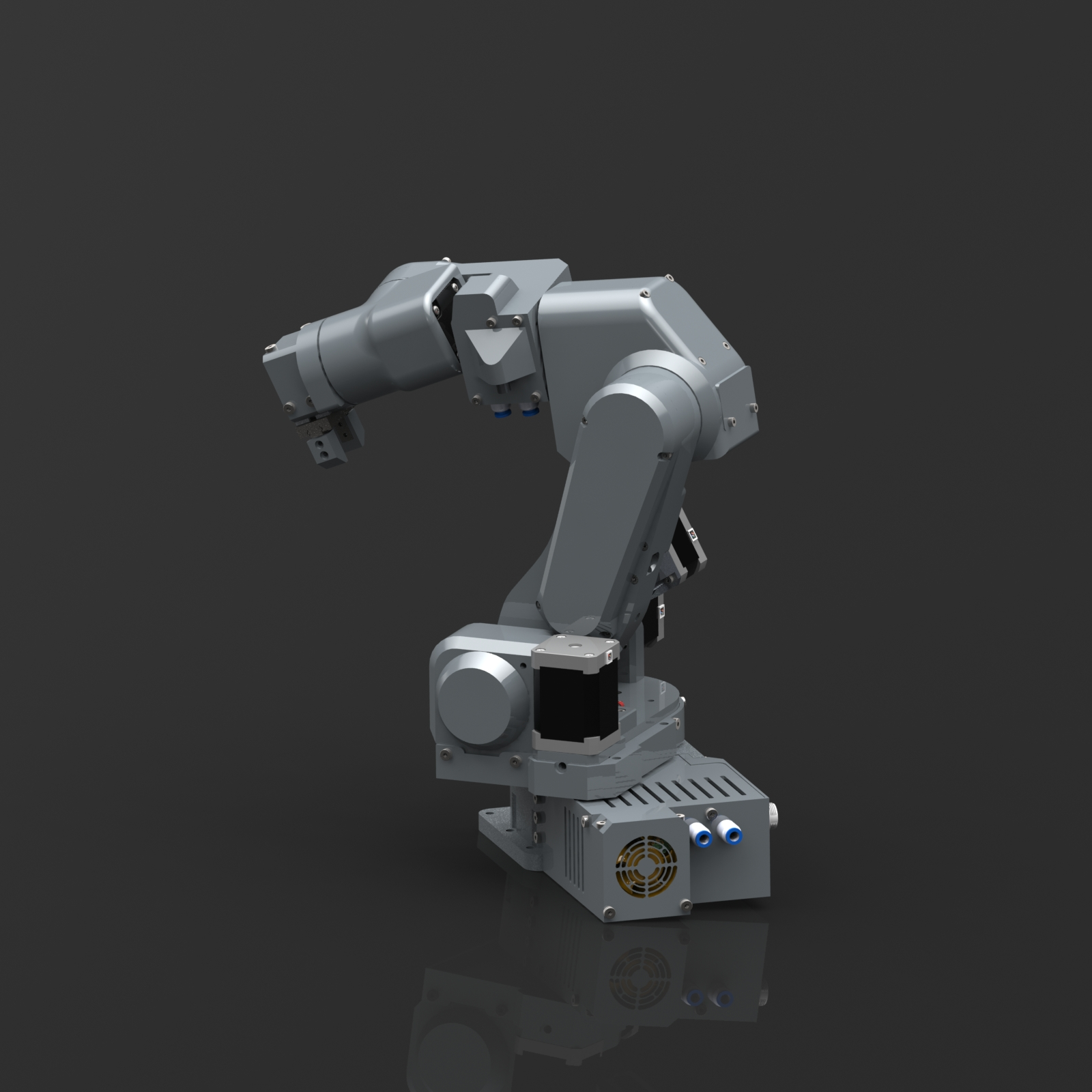
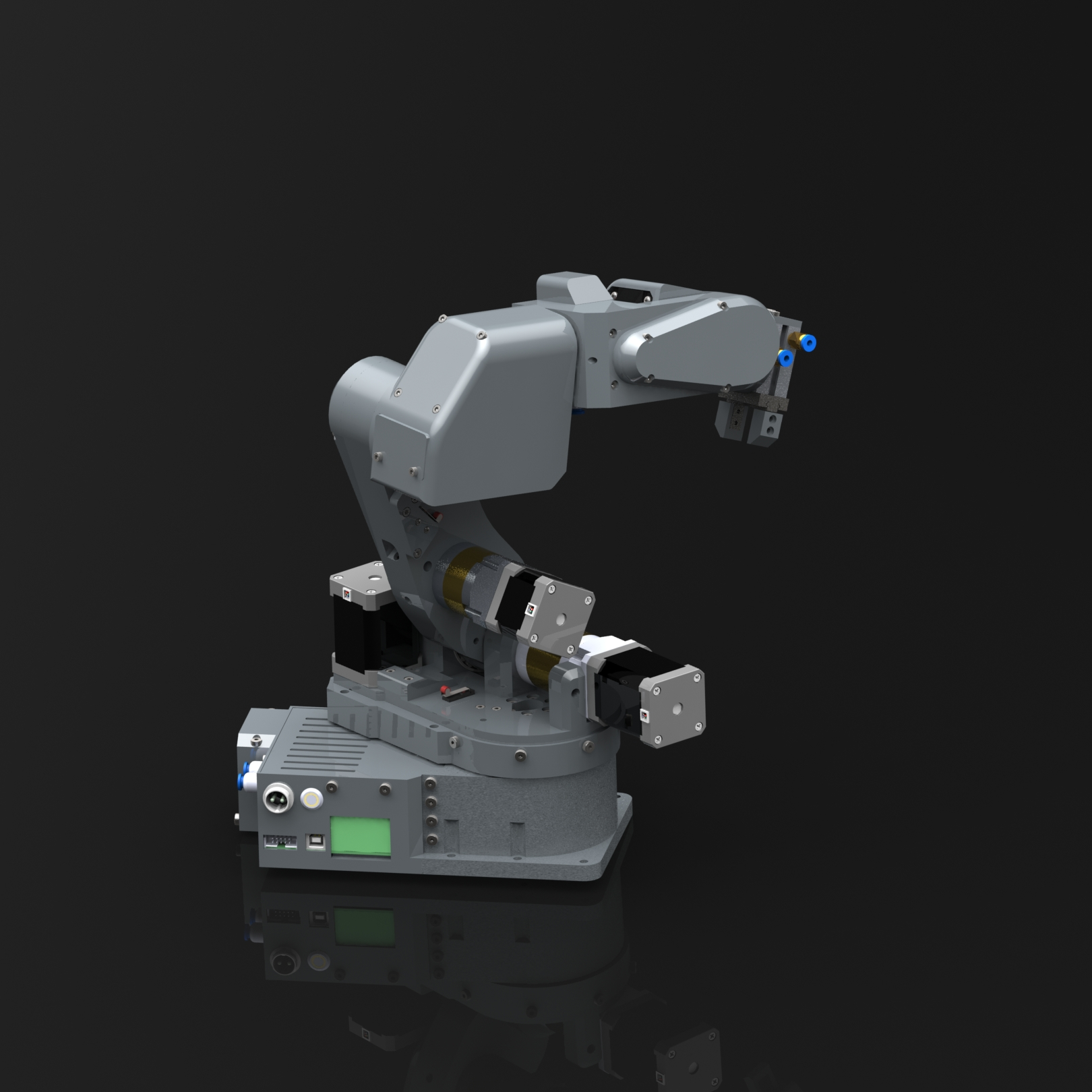
Robot renders!
09/06/2023 at 13:21 • 0 comments![]()
![]()
![]()
![]()
-
PAROL6 mechanical structure
08/21/2023 at 14:42 • 0 commentsDesign Approach
PAROL6 hardware and software design was driven in large part by Faze4 and CM6. From faze 4 mechanical design and from CM6 software and control approach. Advantage of building these robots before this one was the community and contributions to the projects from the people. People build unity simulators, ros control implementation, custom controllers, and modified STEP files... The goal is, like previous robots, to make as much open source as it can. Some of the guidelines that guided the design:
- PAROL6 was built with a specific purpose in mind; Small automation like picking PCBs and placing them in test jigs, adding thru-hole components to PCBs... Another goal was for it to be used in an education setting where one PAROL6 can be used by one student, not 10 students per 1 robot.
- It needs to have a robust simulator and GUI for easy offline programming. The ability to test your programs without a real robot is time-saving and is being done in most professional and industry-standard robots.
- Previous robots of mine used plastic gearboxes and that is a big mistake. They are way too unreliable and bend too much. PAROL6 uses precision planetary gearboxes with 10-15 arcmin backlash (harmonic gearboxes usually have around 5 arcmins). By using quality gearboxes robot has much better repeatability and precision and can make smooth trajectories,
- Robots need good connectivity to interact with the users and the world. PAROL6 has 2 isolated Inputs and 2 isolated outputs for controlling grippers, relays, pneumatics, or connection to PLC-s. It also has a CAN bus for connecting grippers or external devices. To communicate with a PC it uses USB.
- PAROL6 was built with grippers in mind and has routed pneumatic tubes and wires for grippers to its Forearm region.
- A big part of PAROL6 is its software that was again built around Tkinter as GUI and Petar Corke's Python robotic toolbox. That combination has proven to be effective in CM6 and was refined here, Because of that it has a lot of features that no other open-source robotic arm has.
- PAROL6 was designed to be easy to build by using large 3D printed parts and an intuitive design. Also, I believe many DIY robotic arm projects suffer from bad building instructions that lock out some potential users, so PAROL6 has detailed step-by-step building instructions.
WHY planetary gearboxes and belts?
The robot is designed around precision planetary gearboxes on joints that are subject to most torque. These would be joints 2 and 3. Joint one uses belts and a larger motor. For joints 4 and 5 belts are used and for 6 a smaller planetary gearbox. The design was so that motors are not on the axes that they are actuating. By doing that you remove mass to the bottom of the robot and reduce the inertia of the joints. A spherical wrist was used to make inverse kinematics calculations simpler. For the forearm and upper arm section wires and tubes run thru the robot and also from the elbow to the base are hidden. The only section where wires are visible are from the upper arm to the elbow. By hiding wires and tubes they are protected from outside elements like tangling mechanical damage and more.
Motors on most joints are not hidden. By doing that it is easy to add additional closed-loop stepper drivers to the motors and make the robot closed loop.
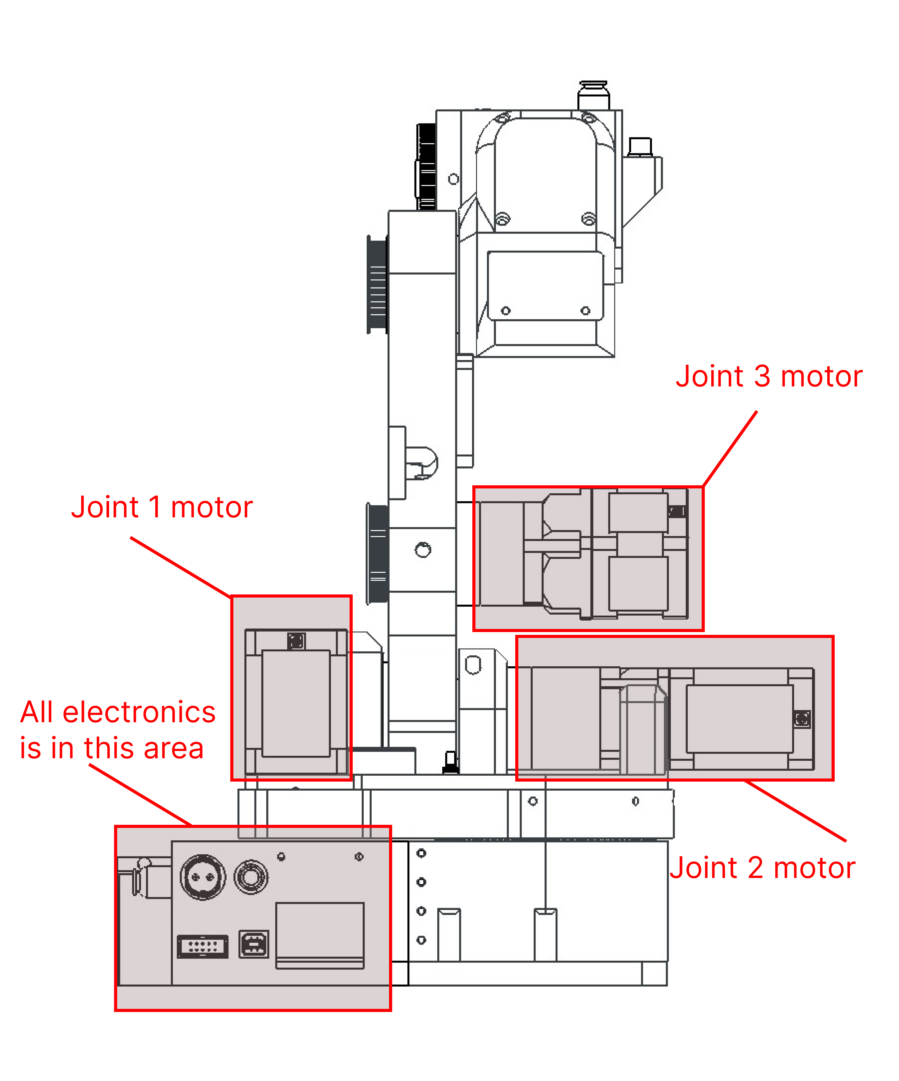
For the joints, 1,2,3 installation of closed-loop drivers is just straight forward as mounting then. For joints 4,5 and 6 minor robot redesign will need to be made for esthetic parts. Only the forearm will need to be extended by 3 cm to allow for PCB to mount on Joint 6.MOTOR LOCATIONS
![]()
![]()
WIRING
Wiring is done similarly to the Faze4 robot except only visible wires are from the upper arm to the elbow. The two images below show how the wiring is done for the robot. Blue are pneumatic tubes while green are wires.
![]()
![]()
BELTS AND TENSION
Belt tension is done with small ball bearings. The usual diameter of the bearing is 8mm if you see that that tension is not enough you can use a 10mm bearing. Bearings can be mounted on both sides of the belts. Joint 1 also uses a belt but it is hidden so taking pictures of it is really hard.
![]()
![]()
![]()
-
PAROL6 detailed software overview and setup
08/21/2023 at 11:19 • 0 commentsPROTOCOL
PAROL6 uses serial USB communication to talk between high and low-level code.
The protocol consists of three types of commands. Active, passive, and carrier. Active commands can only be given by the "command" argument and are represented by one byte. This means there can only be 255 commands.
Passive commands are for example I/O commands and gripper commands. They are always sent with the data packet. Passive commands do not affect the movement of the robot joints and because of that can be injected in any active command.
Carrier commands are joint speeds and positions that are modifiers for active movement commands.
![]()
The above image represents how the data is sent from and to the robot.
Structure of the code
To operate the PAROL6 robot you need a:
High-level software running on your PC
Low-level software running on the PAROL6 control board
For high-level software, there are multiple options:Use PAROL6 commander software for control, programming, and simulating
Use our API to send commands thur your language of choice Matlab, python, c++
Use ROS
For low-level software only PAROL6 control board software is available.![]()
Control software
Control software or the main task in the diagram above is responsible for all robot movements, communication with the robot, executing the code, and calculations... Control software leverages 3 important Python libraries:
* https://github.com/petercorke/robotics-toolbox-python responsible for all kinematics trajectories ...
* https://github.com/ovinc/oclock Used for creating "accurate" loops in Windows and Linux
* Python threading and multiprocessing library
The control software will try to send data to the robot at a predetermined loop time. If you have a good enough PC it will be 10ms but 20ms will be fine if the PC is not good enough. The data it will be sending is defined by the protocol described at the top of this log post. When the robot receives the data it responds with its own parameters.
GUI / control software
GUI / control software is written in Python and the main components are:
- Tkinter for a graphical interface
- CustomTkinter for modern interface design in Tkinter
- Robotic toolbox for Python for kinematics, trajectories...
- multiprocessing library
The control software can be split into 3 processes that run in parallel and share an array of multi-process variables. The main process is then split into 3 threads: Debug, Main/Sender thread and Receive thread.
GUI, user interface
Gui is used for easy interaction between the user and the robot. Its design was inspired by the best of the industry robotics manufacturers.
Some of the features of the GUI are:
- Jogging window where user can perform joint jog, cartesian jog in TRF and WRF
- I/O control
- Robot telemetry data view
- Response log that displays current commands, errors, warnings...
- Program window that allows you to program the robot with simple GCODE-like language
![]()
RESPONSE LOG
A response log is an extremely useful tool for debugging and checking the state of your robot. It will print whatever command is sent to the robot. It will also print if there is any error or warning.
Errors include:
- Temperature errors
- Inverse kinematics errors
- Joint level speed limit error
- Cartesian speed limit error
- ESTOP error
- Disable error
- Position limit error
PROGRAMMING
Programming is done in the programming window of the GUI. Programs are saved as txt files so you can write them in your text editor of choice and open them in GUI. The programming window has options to save, open, and save as the programs.
Commands need to end with ")".
Some of the commands are:
- Delay
- Loop
TRAJECTORIES
There are 2 types of trajectories used for this robot: task space trajectories and joint space trajectories.
Joint space trajectories have faster execution time, there are no IK calculations, and Actuator motion is smooth and easy to validate. Also, there are no inverse kinematics errors or singularities to avoid. Cons are that it is hard to validate where the joints will move in task space thus making it harder to not hit stuff.
Cartesian space trajectories have more predictable motions and are better for handling obstacles and collisions. Cons are that they have slower execution since they need to calculate inverse kinematics at each step. Robots can really easily hit singularities and the robot joints can reach high speeds.
![]()
The image shows trajectories that can be generated with PAROL6 control software.
JOG
The Jog window allows you to move to the robot in real-time. There are 2 types of jogging: Joint level jogging and Cartesian jogging.
Joint level jog jogs only the individual motors.
Cartesian level jogging jogs the robot in x,y, and z axes or rotates around those axes. This means that not only one motor will move to execute that move but all motors of the robot. There are 2 types of cartesian jogging: tool reference frame jogging and world reference frame jogging.
Tool reference frame jog allows you to move/rotate in the x,y, and z axes of the END EFFECTOR reference frame.
World reference frame jog allows you to move/rotate in the x,y, and z axes of the WORLD/Base reference frame.
-
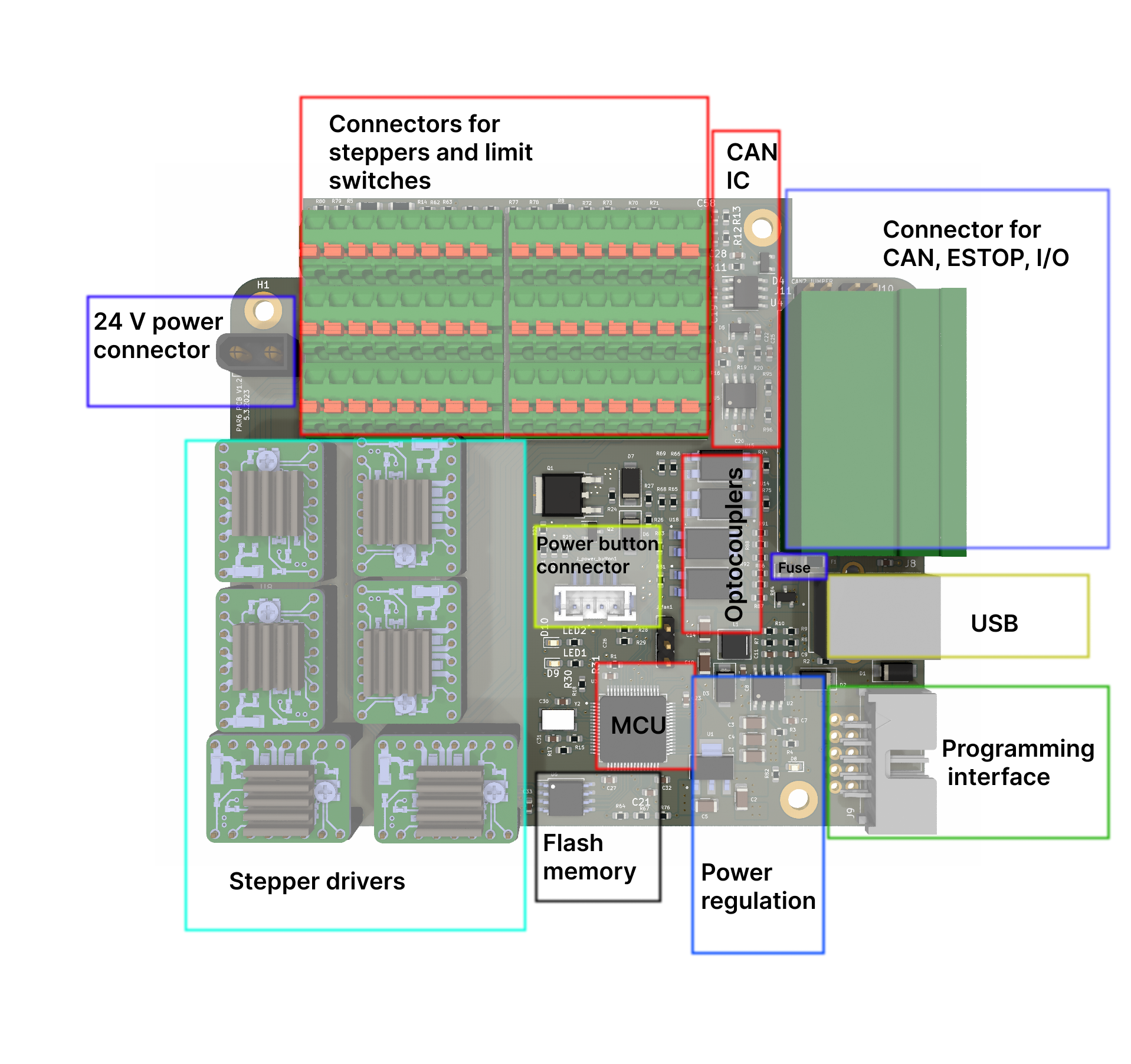
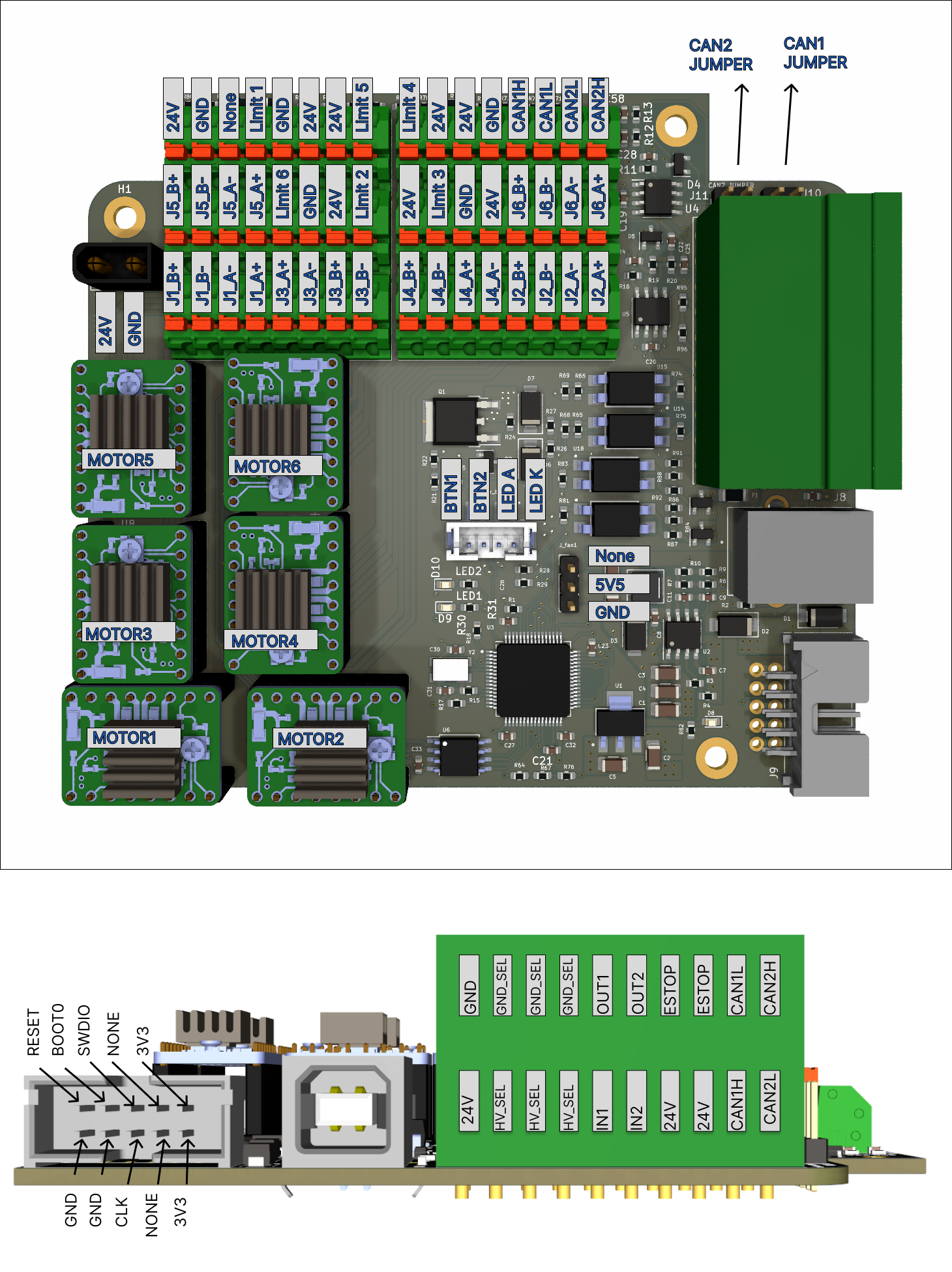
PAROL6 control board
08/20/2023 at 14:44 • 1 commentIntroduction
![]()
The PAROL6 control board is the advanced 32-bit controller for 6 AXES robotic arms like PAROL6. It works out of the box with PAROL6 and PAROL6 commander software.
To use PAROL6 robotic arm you will need a PAROL6 control board. The PAROL6 control board is a compact robotic controller. It is by size a little bigger than a pack of playing cards. It allows PAROL6 to be a really small and portable robot without the need for a control cabinet that is usually the size of the whole robot.
Features
![]()
Hardware specs
- Processor: STM32F446RE
- Processor: features Arm Cortex-M4 core with DSP and FPU, 512 Kbytes of Flash memory, 180 MHz CPU, ART Accelerator
- Communication interfaces: 2 x CAN bus, 1 x USB
- Stepper drivers: TMC5160
- Stepper drivers feature: SPI comms, 10-35V, 3A max, protection features
- Inputs: 2 x ISOLATED
- Outputs: 2 x ISOLATED, 0.5A current output
- Estop input: Dedicated pin on MCU for ESTOP interrupt, 2 ESTOP connections on control board
- Additional memory: W25Q64FV, SPI, 64Mb
- Programming interface: JTAG
- Cooling fan connection: 5V cooling fan
- Connection for a smart power button
Operating limits
Power supply: 18V minimal, 30V maximal voltage
Stepper drivers: Rated current 2.5A, maximal current 3A (Short burst or extreme cooling)
Temperature: xx stepper driver temperature warning, xx temperature error
Isolated Inputs voltage: 24V nominal voltage, min 12V max 50VIsolated Outputs voltage: 24V nominal voltage, min 12V max 50V
Isolated Inputs current: 24V nominal voltage, min 12V max 50V
Isolated Outputs current: 24V nominal voltage, min 12V max 50V
Fuse: Fuse is used for outputs if used in NON-ISOLATED MOD; 2A fuse
Cooling fan: Maximal allowed current draw for the cooling fan is 0.3AConnections
* 24 power connector on PAROL6 control board is XT30 MALE connector.
* Connector for the cooling fan on the PAROL6 control is
* Connector for the power on/off button on the PAROL6 control is
* Connector for USB on PAROL6 control is USB female type B![]()
How to upload code
The microcontroller on the PAROL6 control board is STM32F446RE. To upload code you need to use STlink device and connect it to dedicated CLK, SWDIO, 3V3, and GND pins. You can use jumper cables or dedicated stlink + cable assembly. You can compile your code or use precompiled HEX files.
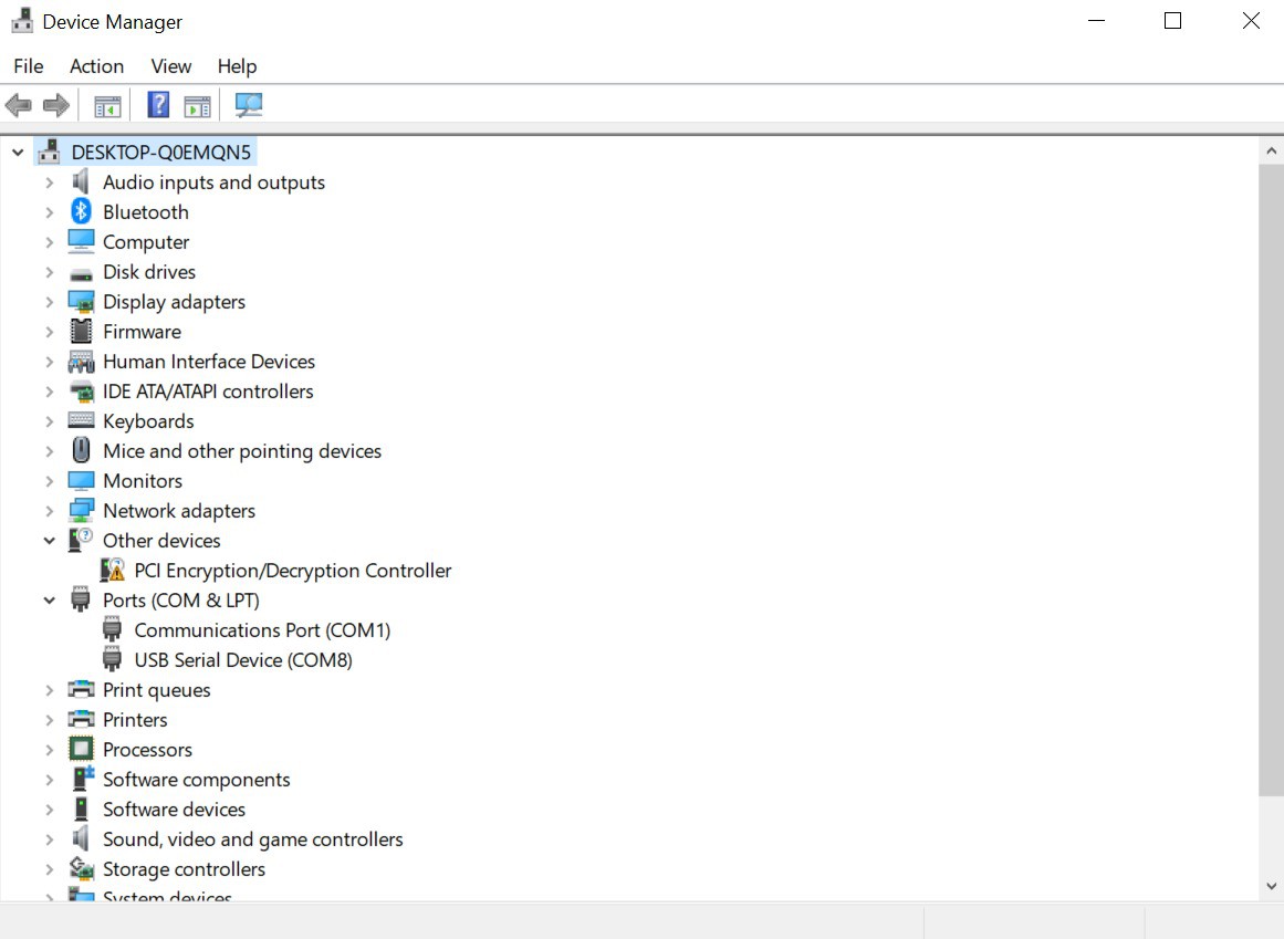
Getting connected
Connect your PCB to the PC with USB cable. NOTE that the board will not get any power, It can be powered up in 2 ways:
- Using 3v3 supply from stlink
- Using 24V supply you connect to the board and then the board drops that supply to 3v3
Once you connect the supply your board should turn on and be recognized on your PC device manager as a USB device.
![]()
Firmware configuration
-
PAROL6 introduction video
08/19/2023 at 14:54 • 0 comments -
Github repo split
08/17/2023 at 17:26 • 0 commentsThe project repo is now split into two parts:
Robot arm repo that has all files to build the robot and PCB files
https://github.com/PCrnjak/PAROL6-Desktop-robot-arm
Commander software
https://github.com/PCrnjak/PAROL-commander-software
This decision was made because the commander software can be used for other robot arms. Because of that, it does not make sense to download a lot of files from the PAROL6 repo just to run the commander.
PAROL6 - Desktop robotic arm
A robot that can be used as desktop tool for small automation and education!