Petar Crnjak
-
Printing table
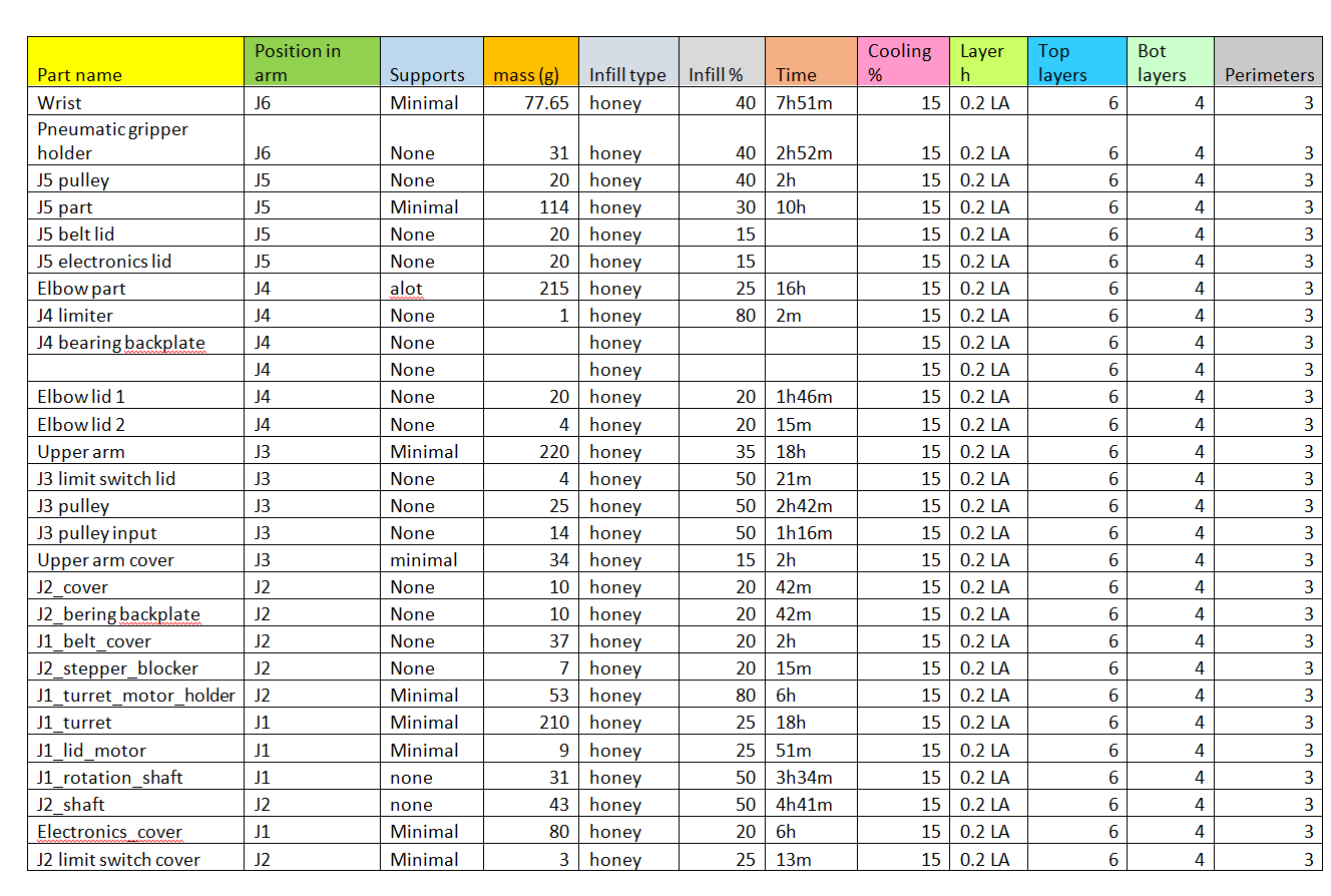
08/17/2023 at 13:35 • 0 commentsThis table lists all values needed for 3D-printed parts of the PAROL6 robotic arm.
![]()
-
Faze4, CM6 and PAROL6 how do they fit together?
08/12/2023 at 09:15 • 0 commentsFAZE4
![]()
As some of you may know I also designed 2 other 3D-printed DIY robot arms; Faze4 and CM6. I would say Faze4 did well in the open-source community and has an active user base. It is mostly used by students as thesis work and just like a DIY robot project. The big mistake I did on the part of Faze4 was that its software and electronics were underdeveloped. It was mostly used as mechanical construction that people used with their own software and electronics. That drove a lot of people away from the project since they wanted a complete solution.
CM6
![]()
CM6 is a compliant robot arm that is much more complex in terms of control and electronics. It uses BLDC gimbal motors paired with custom-made BLDC drivers called S-drives. CM6 compared to Faze4 was technologically much more complex and I contribute that to its moderate success. The drives I designed were hard to make and were hit hard by covid and chip shortage. People that wanted to build it could not and to be honest there was I lot of work that needed to be done on the software and control side that I just did not know how to do at that time. Driver electronics were also quite basic. At the time I believed I did everything right and that S-drives were something special but I was way too wrong. Since then I worked in startups designing inverters and electronics for electric vehicles like cars, bikes, and delivery vehicles. And only now I can say that I could design industry-level electronics and control algorithms for something like CM6.
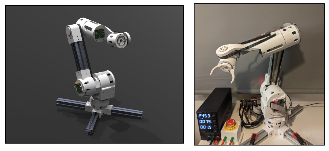
PAROL6
![]()
Now we come to PAROL6. Best of both worlds. Mechanical elegance of Faze4 and control and electronics inspired by CM6. PAROL6 was created to be a new standard for open-source robotic arms. But it was also designed with the goal to revive Faze4 and CM6. It was also designed to assist any robot arm builder by providing a electronics and control software/GUI/API stack they can build their mechanical structure on top of.
PAROL6 and FAZE4 integration
PAROL6 electronics and software will be really easy to integrate into Faze4 since both are open-loop stepper-controlled robot arms with limit switches. What this means is that ANY open loop 6 axes stepper robot will be able to use PAROL6 electronics and software platform to develop.
PAROL6 and CM6 integration
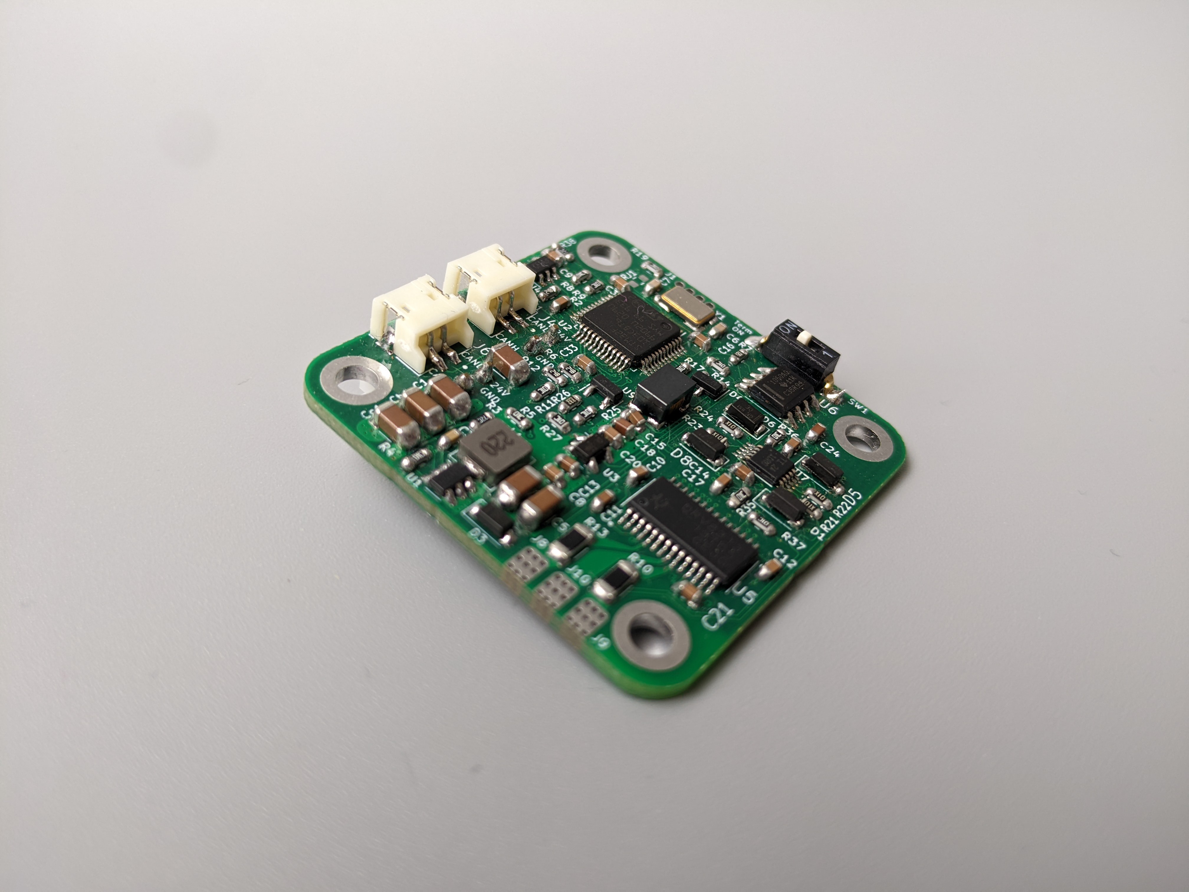
PAROL6 uses open-loop steppers. The trinamic stepper drivers are in the base of the robot and are responsible for the movement of the joints. This works really well but robots need to be a closed-loop for much better performance and safety. PAROL6 was made with that in mind and can be easily upgraded with closed-loop stepper drivers that are being developed.
By doing that robot becomes closer to CM6 and guess what, new drivers for CM6 are also being developed. They would be able to daisy chain and reduce wiring, have current sensing for torque control, 14-bit magnetic encoders, safety features, and much more.
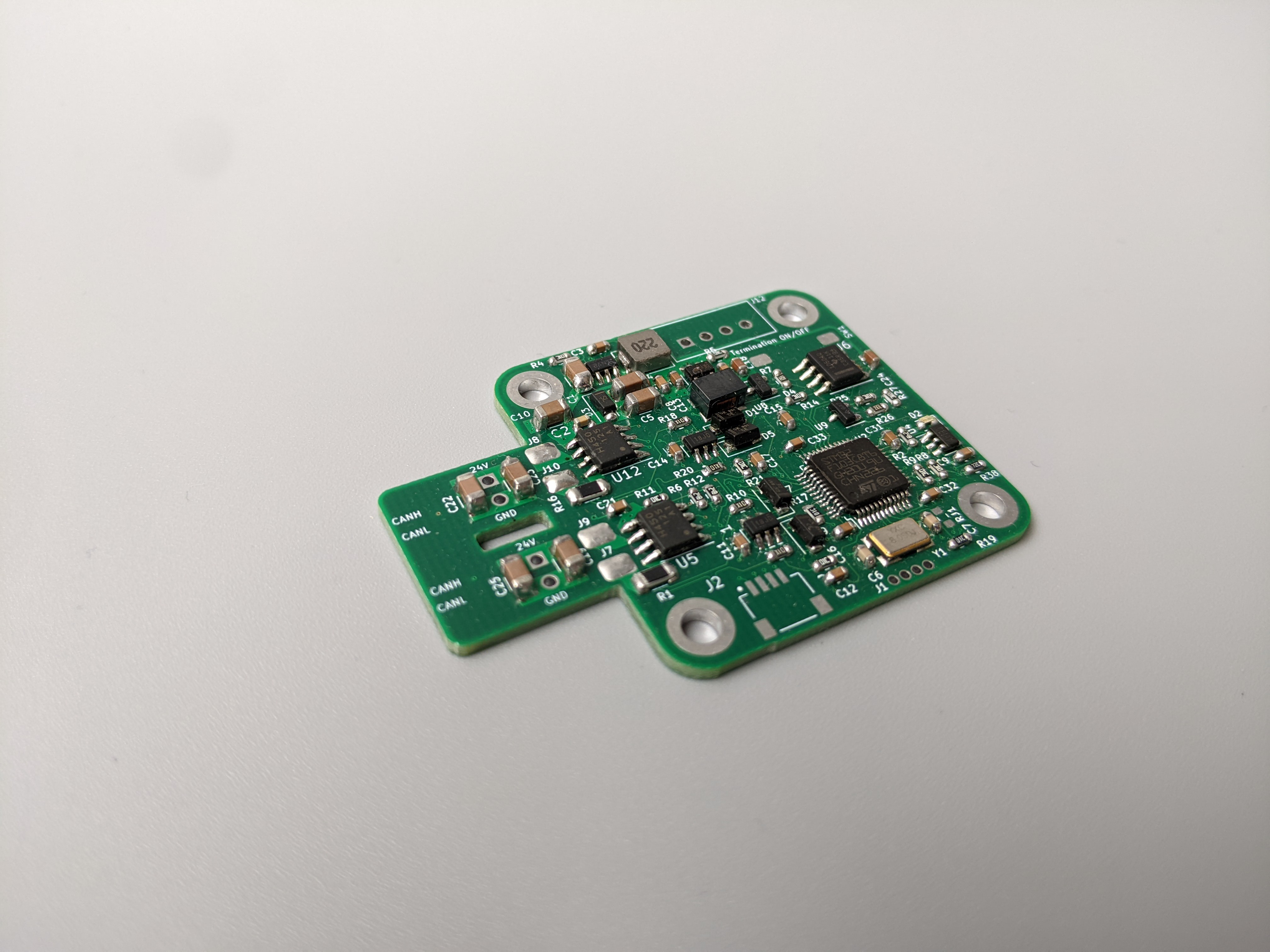
![]()
Image of stepper driver for PAROL6. It is a small 39mm x 39mm board that fits on top of the NEMA 17 stepper module. The driver can run the FOC algorithm on stepper motors.
![]()
This is a driver for small BLDC gimbal motors. It is by design really similar to the stepper driver for PAROL6 except it is designed for 3-phase gimbal motors. It is perfect for CM6 robotic arm and expect to see a post about the new and upgraded CM6 soon!
-
3D printing waste and prototyping
08/12/2023 at 08:51 • 0 comments![]()
The picture above shows all the failed parts printed for PAROL6 robot. It was not the printer that failed but the engineer. I will write a short entry on how to reduce waste when 3D printing by doing the right design choices and checks.
* Do not rush to start printing your (LARGE) parts! If printing something bigger like 24h+ prints double-check all the features you need for your part to have are there.
* With small prints you don't need to worry about failing, they take 30 mins to print and in the same batch you can place several different versions of the same part and test what is a better fit or what works best.
* If printing large parts that need to mate with a lot of other parts first print some segments of that parts where tolerances need to be hit to a spot. For example, I have a print that will take 30h and one of the things that NEEDS to work is that bearing that that part holds is a tight fit. What I usually do is print just a hole that holds a bearing from the original part and test the tolerances. This will save you a ton of time trust me
* Top-down design and bottom-up design.
Top-down modeling involves generating and designing the geometry exclusively within an assembly, a technique often referred to as "in-context design." In this method, all elements are crafted within the assembly's framework.
Conversely, the alternative approach is known as bottom-up assembly modeling, where each individual part is conceived independently.
These are 2 methods you can use to design your complex assemblies. I usually go with Top-down design since I have more control over the project as a whole. For example, for PAROL6 the design was from the wrist to the base. So the first part I designed was the wrist part and then in the context of an assembly, I designed the forearm, then the elbow... Then I printed every part as I was designing it ( after designing the next part it mates too) So after designing the wrist I still did not print it, it was printed after the forearm was designed.
By printing part by part like that you can see if you did a mistake somewhere and just redesign that part and print a new one. You will not need to disassemble the whole robot that way to replace that part.
* Place all the screws and mechanical parts in your assembly! I know it is boring and you want to print your part as soon as possible but placing parts you did not draw (like screws, bearings, nuts...) really helps.
-
Compliant gripper
08/12/2023 at 08:40 • 0 commentsThe robot arm is not really useful without a way to interact with the world. That interaction is usually done with pneumatic or electric grippers. Pneumatic grippers are great: They are small and compact, and you can exert the exact force you want by controlling the pressure they are fast and robust. BUT they require a lot of equipment, expensive and LOUD compressors, pneumatic valves, tubing...
![]()
The solution to that is electric grippers.
While pneumatic grippers tend to offer higher gripping force compared to electric grippers, the latter are becoming increasingly robust each year. Despite their lower gripping force, electric grippers excel in granting users precise control over factors like speed, force, and position.
One notable advantage of many electric grippers is their object detection capability, which verifies successful part pickup. Moreover, electric grippers allow the management of grip force and closing speed. This attribute is particularly vital when handling delicate items that require gentle manipulation. Unlike conventional grippers that typically function with a full stroke, servo-electric grippers can be partially opened, enabling them to adeptly grasp a diverse array of parts varying in size.
For tasks demanding precise assembly, electric grippers prove to be an excellent choice. Similarly, scenarios involving part sorting necessitate grippers with adaptable capabilities to accommodate varying sizes and orientations. While advanced pneumatic grippers offer some of this flexibility, electric grippers surpass them with greater versatility and simplified adjustments for different object types.
Most manufacturing facilities have access to an air supply, simplifying the integration of pneumatic grippers. Nevertheless, the absence of an air supply requirement makes the deployment of electric grippers even more convenient, translating to lower operating costs. In applications demanding a clean environment, electric grippers emerge as the safer option, eliminating the risk of air leaks.
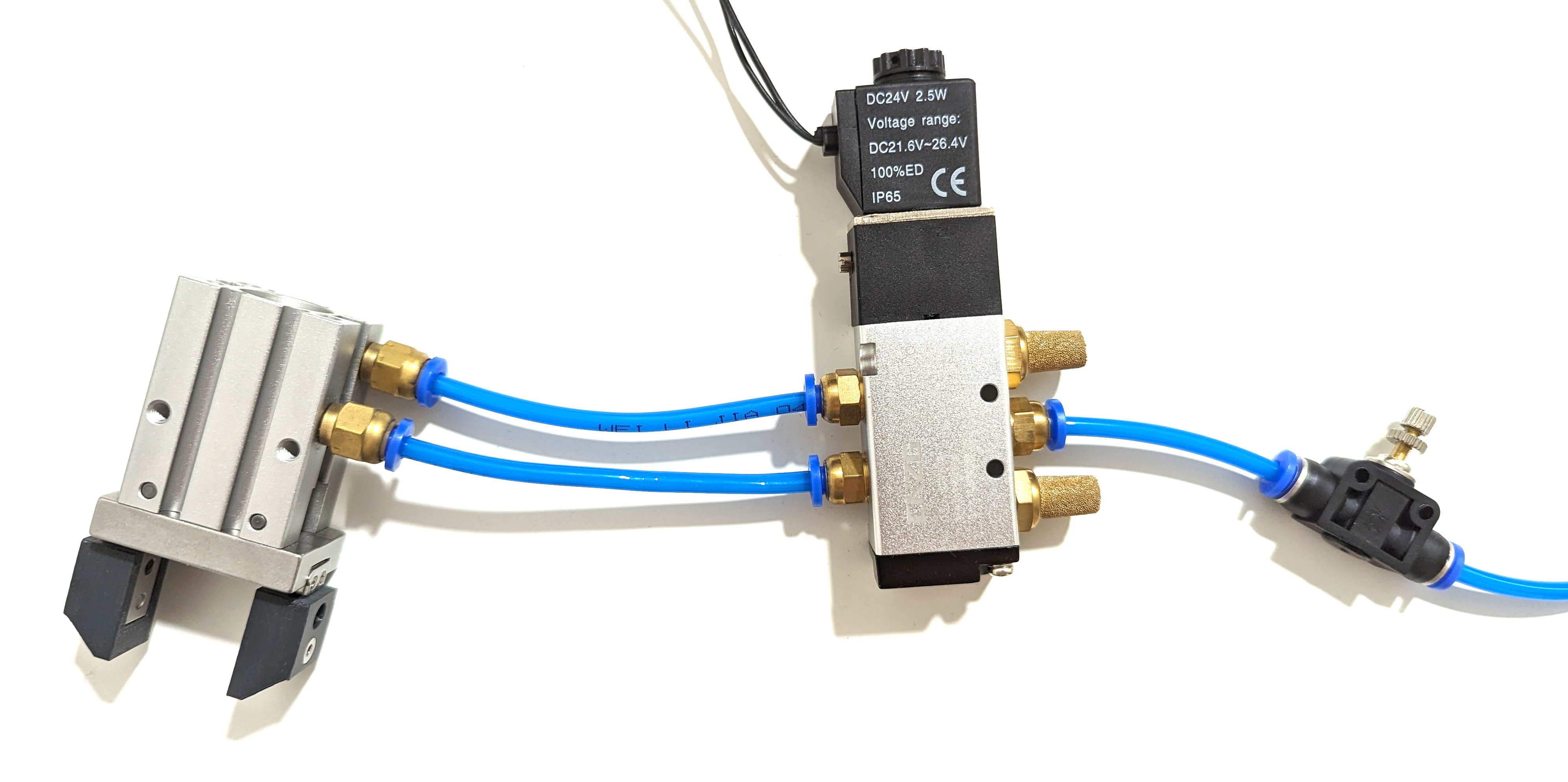
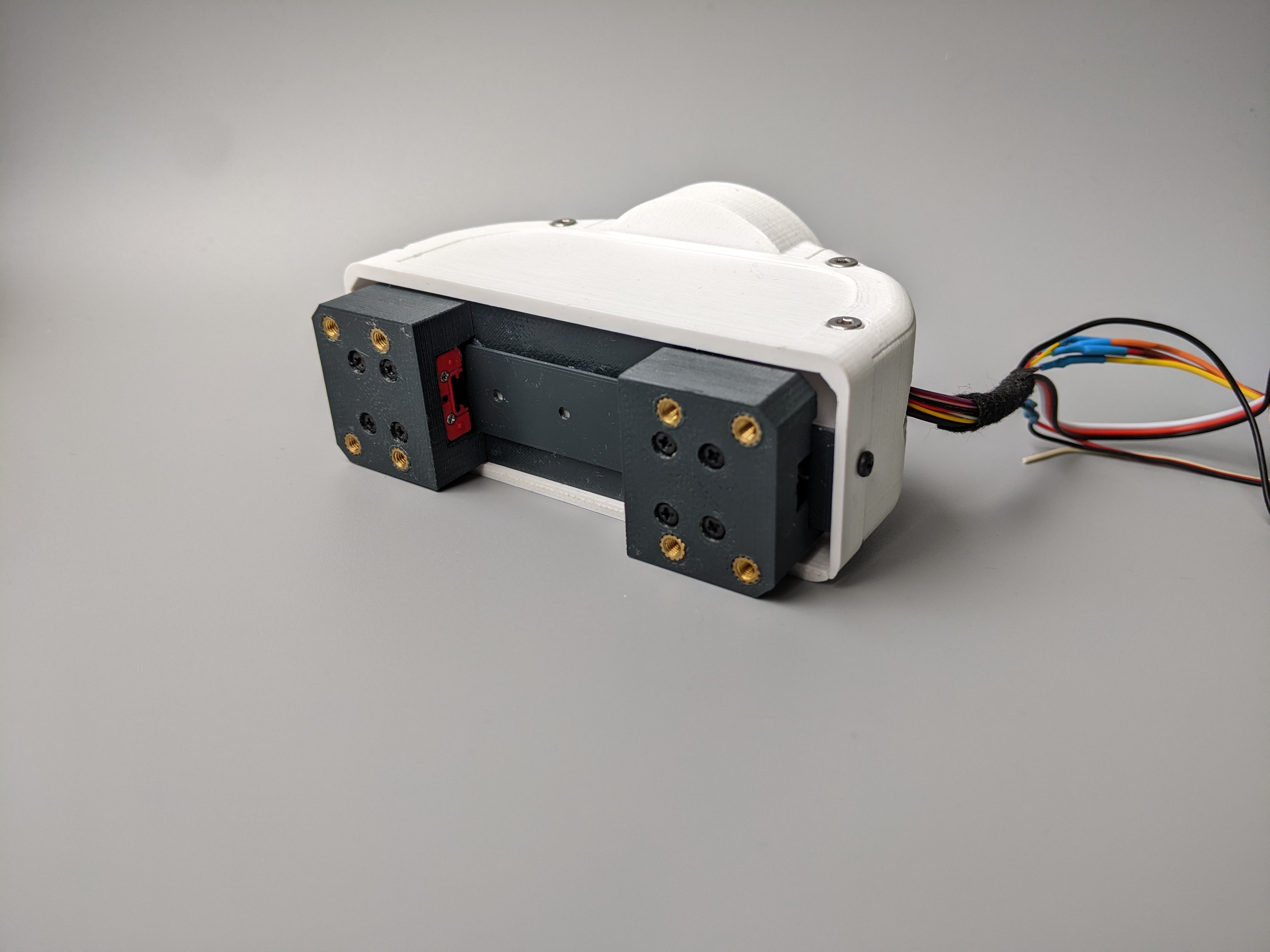
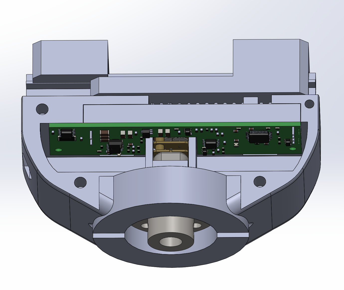
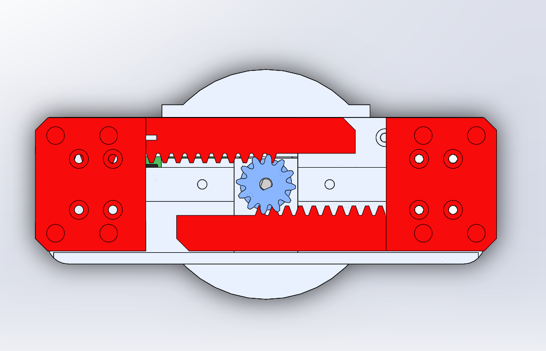
So electric grippers are the new hot stuff, but there are zero cheap or open-source grippers you can buy/make. Well, when designing PAROL6 I had that in mind and created a small compact electric gripper with force control.
![]()
It uses a DC motor to actuate its jaws. Each jaw is connected to a rack that is in turn controlled by a pinion that is connected to the DC motor gearbox. To one of the racks is connected a linear potentiometer that allows precise position control. Torque control is done via shunt current sensing. Communication is done via the CAN bus.
![]()
![]()
-
PAROL6 Repetability and accuracy
08/11/2023 at 18:42 • 0 commentsHow do we differentiate between robots? Is a robot with hobby servos the same as a 30000 dollar industrial robot? Of course not. Industrial robots have stiffer parts, motors are more precise, motion algorithms and motor controllers are advanced... All this and more dictates how usable the robot will be. Some of the aspects that describe that robot usability are accuracy, repeatability, payload, speed, reach, safety... In the field of robotics, there is often confusion between the definitions of repeatability and accuracy when discussing these concepts. Here we will only discuss robot accuracy and repeatability.
- Accuracy: accuracy refers to the ability of a robotic arm to consistently reach a specific target point accurately. It measures how closely the robot can position its end effector (such as a tool or gripper) to a desired location in space. Roughly speaking accuracy is the error between the requested task and the task that the robot did. What affects robot precision: Mechanical design, backlash, encoder feedback, control software, calibration, wear, payload...
- Repeatability: Repeatability, on the other hand, refers to the robot's ability to consistently return to a programmed position or target point. It assesses the robot's capability to repeatedly perform the same motion or task and consistently reach the same position each time it executes the movement. Repeatability takes into account variations that might occur due to factors like mechanical play, backlash, or environmental conditions. In broad terms, the repeatability of a robot might is the ability to achieve repetition of the same task.
This clip is just a short demonstration of PAROL6 repeatability and its abilities. In the future, more tests will be done with load and more complex arm movements to see what real repeatability is! But nevertheless, this Is a cool example of what this arm is capable of and what to expect of it!
Also, keep in mind that this is first prototype that had at least 7 months of extensive testing, crashing, overheating, and every bad thing imaginable that can happen to a robot.
-
PAROL6 design choices
08/11/2023 at 17:30 • 0 commentsThere are six types of industrial robots:
• Vertically articulated.
• Cartesian.
• Cylindrical.
• Polar.
• Selective compliance assembly robot arm (SCARA).
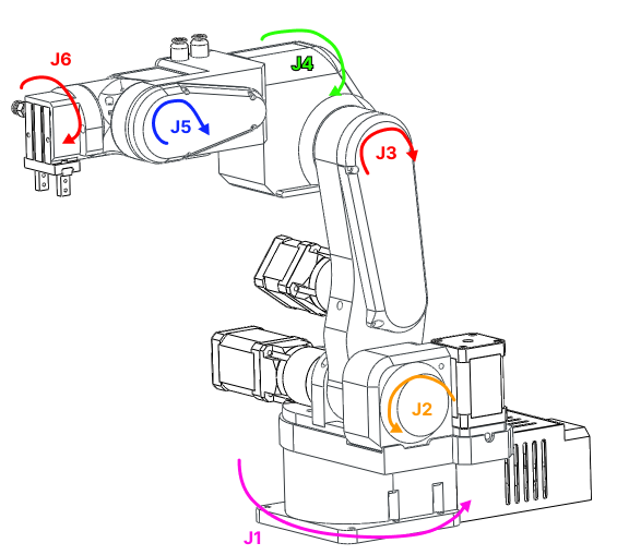
• DeltaPAROL6 falls in the category of vertically articulated 6 axes robotic arms.
6 axes means it has 6 joints in our case 6 rotational joints. Joints are connected with links.
![]()
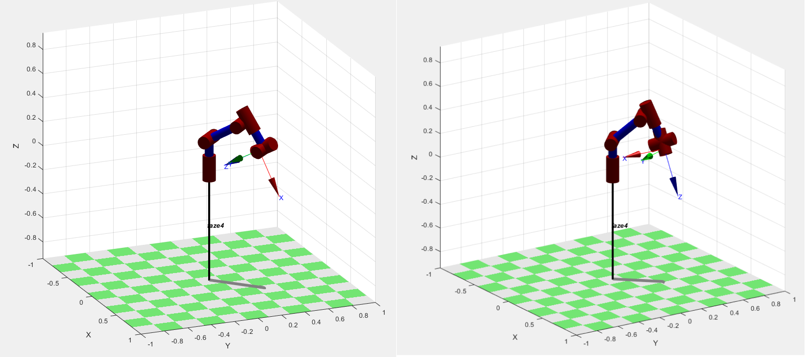
The advantage of robot arms of this type is that they can get to the same position in space with different orientations. Both pictures show the arm at position x=0.3m, y=0.3m, and z=0.2m but as you can see orientations are different. Robot's pose in 3D space is described by the position and orientation ( rotation) of the robot's end effector in 3D space.
![]()
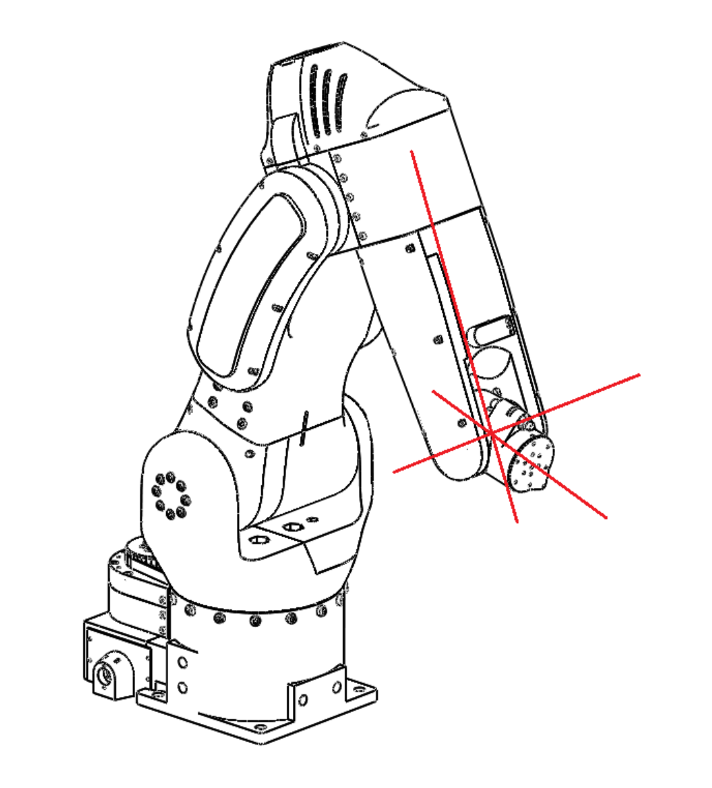
The first 3 axes are used to position the end effector in cartesian space while the last 3 joints are used to change the end effector orientation. PAROL6 uses a popular configuration where the axes of rotation of the last 3 joints intersect. That configuration is called a spherical wrist and is one of the most common configurations you will see in industrial robots. A spherical wrist allows for much easier and faster calculation of inverse kinematics. You can see an example of a spherical wrist on the example of Faze4 robotic arm in the image below.
![]()
-
PAROL6 kinematic structure
08/11/2023 at 14:44 • 0 commentsThis project log will be a little bit longer and full of silly robot theories and facts that you should know if using any kind of robot!
A kinematic diagram of a robotic arm is a simplified graphical representation that illustrates the arrangement of links and joints in the robotic arm. It serves to convey the essential geometric and kinematic relationships between the various components of the arm without necessarily capturing all the physical details.
In a kinematic diagram of a robotic arm:
- Links: The links represent the rigid segments or sections of the robotic arm. These could be actual physical components or conceptual representations. Links are typically depicted as straight lines connecting joints.
- Joints: The joints represent the articulation points where motion occurs. These can include revolute joints (rotational) and prismatic joints (linear). Joints are often shown as small circles or symbols, with appropriate labels indicating the type of joint and possibly its degree of freedom.
- Degrees of Freedom: The diagram may indicate the number of degrees of freedom associated with each joint, which specifies the number of independent ways that the joint can move. This information helps in understanding the arm's overall motion capabilities.
- Dimensions and Parameters: The diagram might include dimensions, angles, and lengths of the links and joint axes, which are essential for understanding the arm's geometry and for performing kinematic calculations.
- Coordinate Frames: Coordinate frames or axes are often included at each joint to show the orientation and position of each joint relative to a common reference frame. These frames help in defining the transformations between different segments of the arm.
- Motion Arrows: Motion arrows or annotations may be used to indicate the allowed range of motion or direction of movement for each joint.
A kinematic diagram provides a clear visual representation of the robotic arm's structure and kinematic relationships, making it easier to analyze and understand its behavior without delving into complex mathematical equations or detailed physical designs. It's a valuable tool for initial design, analysis, and communication among engineers, researchers, and anyone interested in robotics.
Inverse kinematics is a fundamental concept in robotics that involves determining the joint angles or parameters of a robotic mechanism in order to achieve a desired end-effector position and orientation. In simpler terms, it's the process of calculating the joint configurations that will result in a specific pose (position and orientation) of the robot's end-effector (e.g., its hand or tool).
In a robotic arm, for example, the forward kinematics process involves calculating the position and orientation of the end-effector based on the given joint angles. Inverse kinematics, on the other hand, works the opposite way: given a desired position and orientation for the end-effector, it calculates the joint angles that will achieve that particular pose.
Inverse kinematics can be quite complex, especially for robots with multiple joints and degrees of freedom. Solving inverse kinematics involves finding solutions to sets of nonlinear equations that relate the joint variables to the desired end-effector pose. Depending on the robot's geometry and the specific task at hand, there may be multiple solutions, a unique solution, or even no solution.
Inverse kinematics is crucial for tasks such as trajectory planning, motion control, and object manipulation, as it allows the robot to determine how to move its joints to achieve a specific goal in its operational environment. It's used in applications ranging from industrial robotics and automation to animation and simulation.
![]()
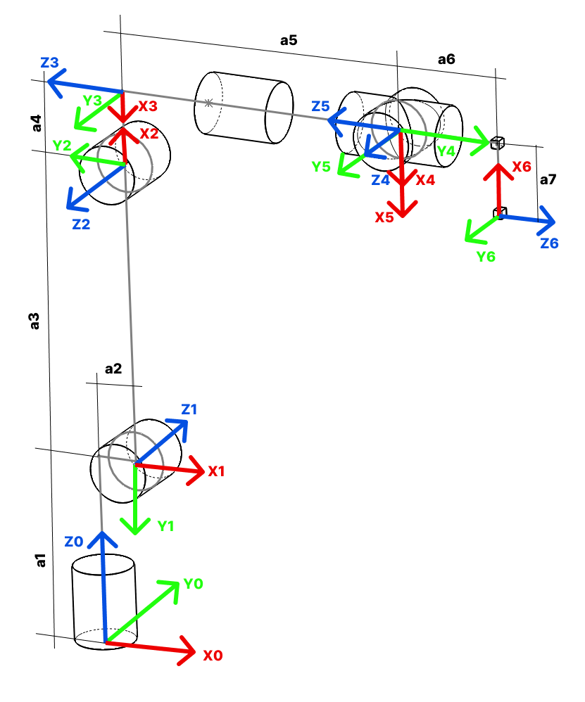
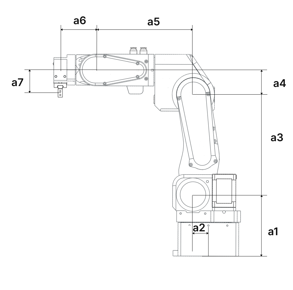
Image 1 - kinematic diagram of PAROL6 robotic arm.
![]()
Image 2 - kinematic diagram of PAROL6 robotic arm.
Link lengths!
a1 110.50 mm a2 23.42 mm a3 180.00 mm a4 43.50 mm a5 176.35 mm a6 62.8 mm a7 45.25 mm Denavit-Hartenberg parameters are a set of standardized parameters used to describe the geometry and kinematics of robotic arms and mechanisms. They provide a systematic way to represent the transformation between consecutive coordinate frames along a robot's kinematic chain. These parameters were introduced by Jacques Denavit and Richard S. Hartenberg in the 1950s and have become a fundamental tool in robotics.
The Denavit-Hartenberg parameters consist of four values associated with each joint of a robotic arm:
- Link Length (a): The distance between the common normal (perpendicular) to the current and next joint axes, measured along the previous joint axis.
- Link Twist (α): The angle between the common normal of the current and next joint axes, measured along the previous joint axis.
- Link Offset (d): The distance between the joint axes along the common normal, measured along the current joint axis.
- Joint Angle (θ): The angle of rotation or translation about the current joint axis to align the coordinate frames.
These parameters are defined for each pair of consecutive joints in the robot's kinematic chain. By applying a sequence of transformations using these parameters, you can calculate the overall transformation matrix that represents the position and orientation of each link relative to a reference frame.
The Denavit-Hartenberg parameters provide a consistent and concise way to model and analyze the kinematics of complex robotic systems, making them a widely used approach in robot design, control, and simulation.
Joint angle Link twist Link offset Link len JOINT LINK(n,i) θ THETA α ALPHA r,a [mm] d [mm] 1 Base TH1 -pi/2 a2 a1 2 Shoulder TH2 - pi/2 pi a3 0 3 Elbow TH3 + pi pi/2 -a4 0 4 Wrist 1 TH4 -pi/2 0 -a5 5 Wrist 2 TH5 pi/2 0 0 6 Wrist 3 TH6 + pi pi -a7 -a6
PAROL6 - Desktop robotic arm
A robot that can be used as desktop tool for small automation and education!