Mirko
Mirko-
Openthing 2 - RepTrap OUT NOW!
01/14/2025 at 13:48 • 0 commentsHey Friends of open-source stuff!
My Openthing 2 RepTrap Camera Sensor is now available on Tindie.
![I sell on Tindie]()
The device comes with a Camera Trigger Cable and a Trigger Extension Cable. I've got a Triggering Cable for lots of different cameras, you can find a list in the description.
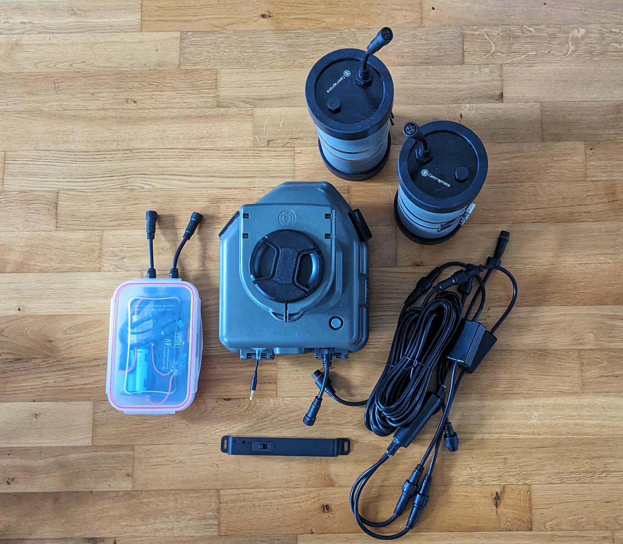
I also got myself a whole setup to secure my camera within an enclosure from
https://www.camtraptions.com/![]()
There are multiple different things which you can buy and they have a nice guide which you can find here. I went for the following list of items:
- Male to Male Waterproof 2m Cable × 1
- 6V Ni-MH Rechargeable Flash Batteries × 1 10Ah Capacity
- Camera Power Splitter × 1
- Flash Cables × 4 0.3 metre
- Flash to DC Socket Power Adapter × 2
- Male to Female Waterproof 5m Cable × 2
- Male to Male Waterproof Flash Cable × 2
- Waterproof Splitter Cable × 1 2-way
- Female Waterproof Enclosure Entry Cable × 5
- Tamiya to DC Socket Adapter × 1
- External Battery System for Cameras × 1 Nikon EN-EL15 / NP-F Adapter Included
- Flash Splitter Cables × 1
- Flash Hot Shoe Adapter × 1
- Ni-MH Compact Charger × 1 Ni-MH Compact Charger (EU Plug)
- Flash Housing × 2 Clear
- Z2 Camera Trap Zoom Flash × 2
- Camera Housing × 1
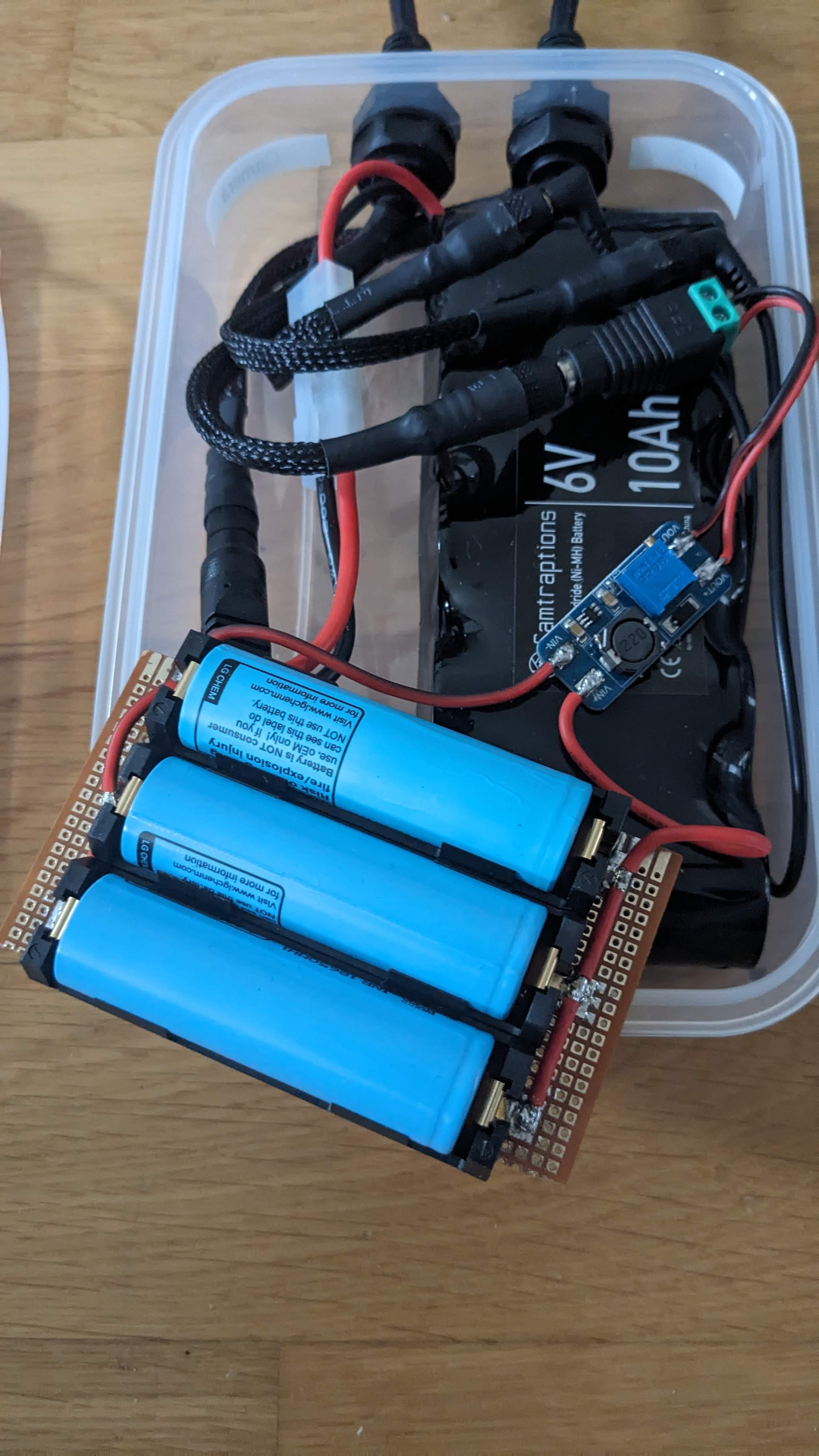
Instead of getting myself a super expensive external Batterypack for the camera, I made one myself with 3 x 18650 Batteries (~2300 mAh each, 6900 mAh together) and a DC to DC Buck Boost Converter bringing the 4.2V of the batteries up to 7V (depending on the camera and its battery type). With that setup I should get a runtime of maybe 3 Month or more?
I still need to find a way to also include the sensor into this battery setup, because the internal battery within the sensor will only last ~3 days.
![]()
The list above was around 1000€ which is super expensive and I believe there is a cheaper way to protect the camera from moist. On the other hand this project is supposed to run in a rain-forest as well. I was there - nothing survives the rain-forest. My wallet which was hidden deep in my backpack was growing mushrooms after just one month being there.
To make the enclosure a bit cheaper you can go with only one flash of course and reduce the amount of cables needed. You could think about using the normal cables as well instead of the waterproof versions. Then you would need to place one smaller battery together with the flash into its enclosure so the power is directly inside the flash-enclosure and the same you can do with the camera.
The cable for triggering has no real power in it so nothing can be shorted there, it does not really need to be waterproof (of course it is always better to do so). If it shorts because of water or corrosion it might stop triggering or falsely trigger the camera at some point but you could simply protect the connections with hot glue or something similar. That way you might save some money. A 5m normal trigger cable costs around 6€ and the waterproof version 20€. Also one flash costs ~106€ + the enclosure 48€ so using just one flash can safe you 160€ and a bit more.
I went with the waterproof versions because I hope it will last much longer.
-
I need help and a name...
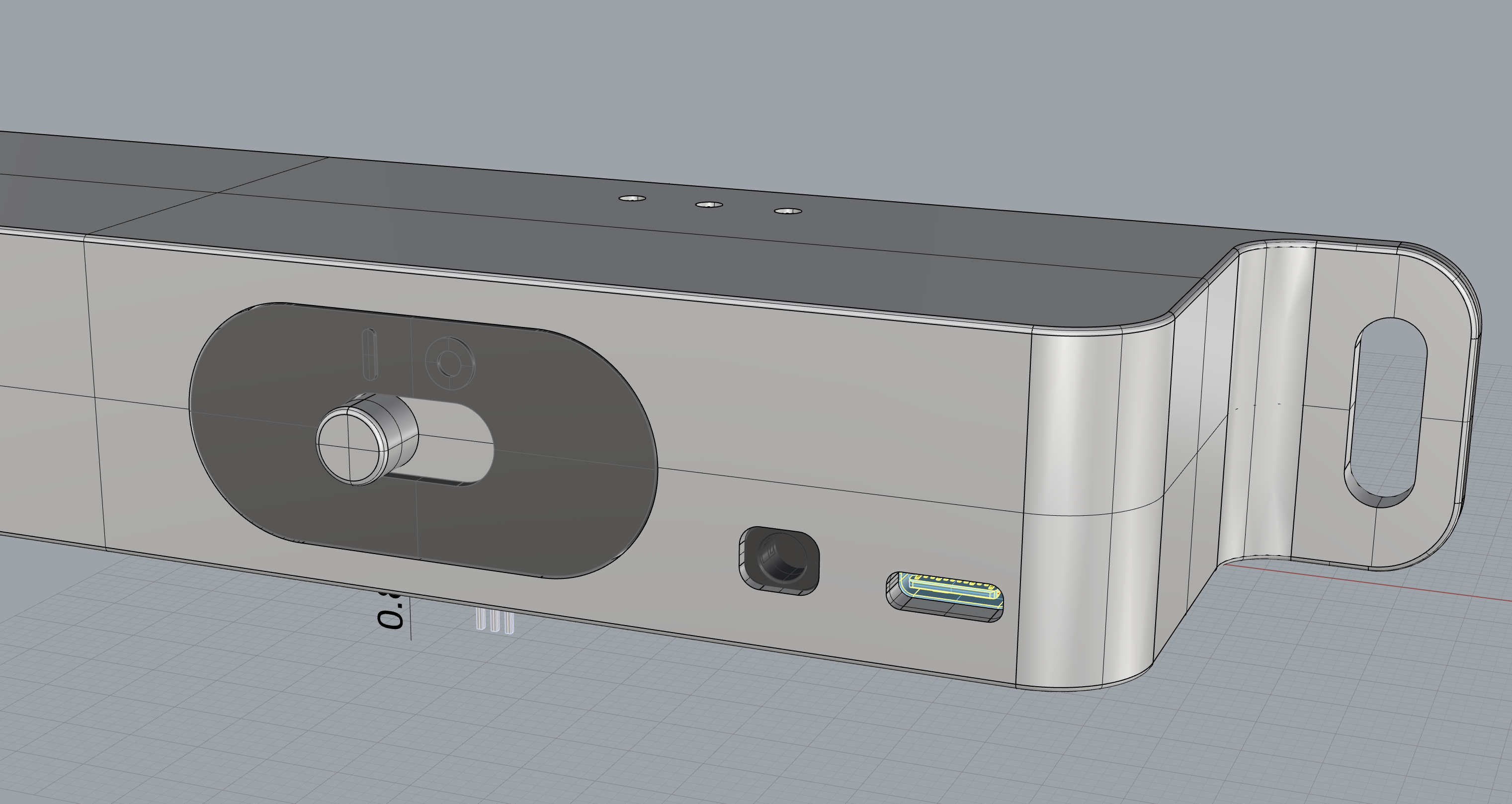
05/04/2024 at 09:10 • 0 commentsAfter quite some time, I've gathered everything for the entire device:- A CNC-machined aluminum enclosure (very nice and durable),
- an IR-filter cover glass,
- screws to mount the PCB inside the enclosure,
- the PCB itself! (very important),
- the code (written in Toit) including BLE OTA capabilities,
- the magnet switch.
![]()
![]()
![]()
I am not so happy with the name anymore but I can not come up with a better one then RepTrap. Do you have suggestions? Please comment them!
I also have trouble with the Firmware and the 4 ToF Sensors if anyone wants to help and try to figure out what the issue actually is please contact me.
-
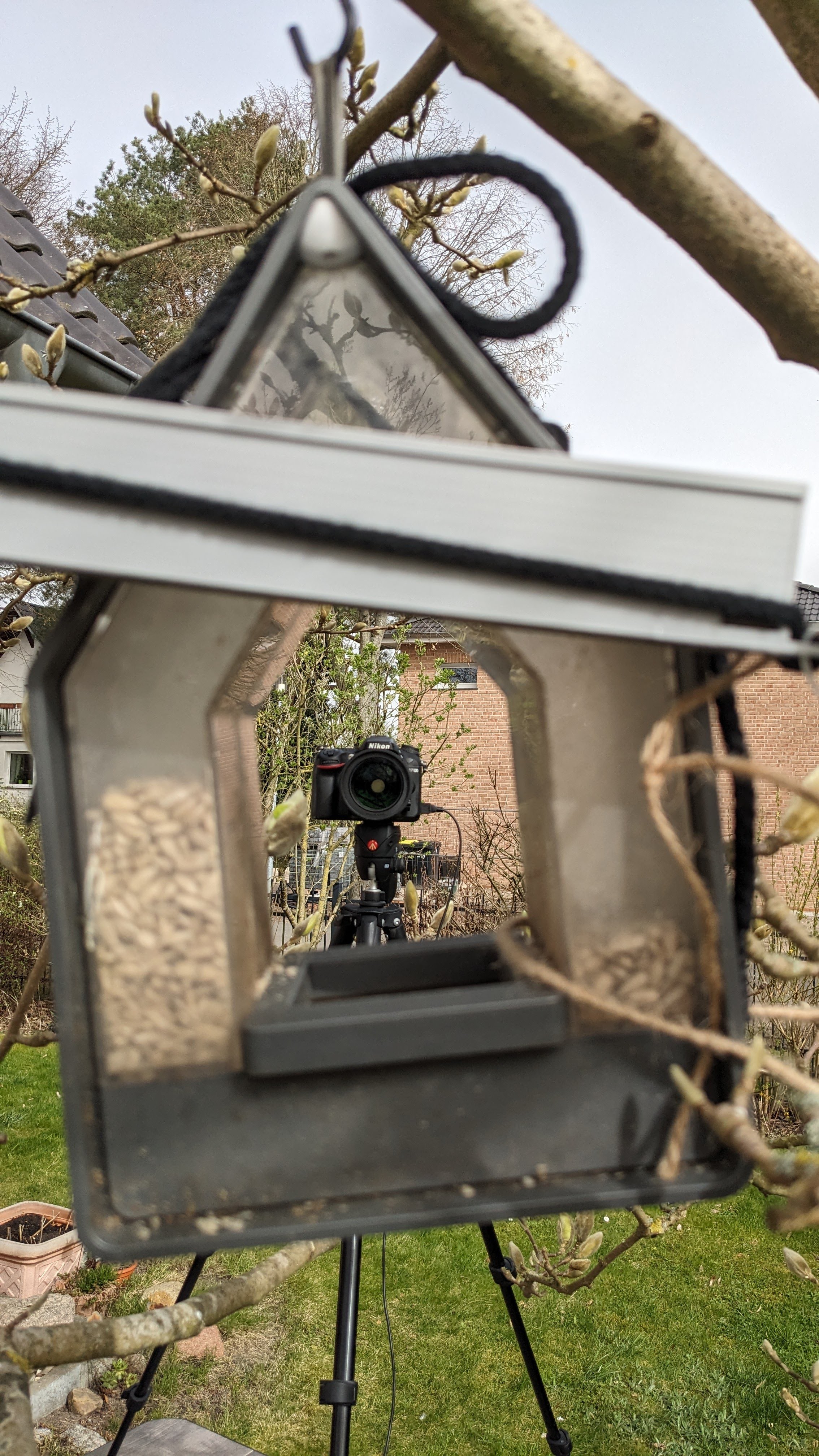
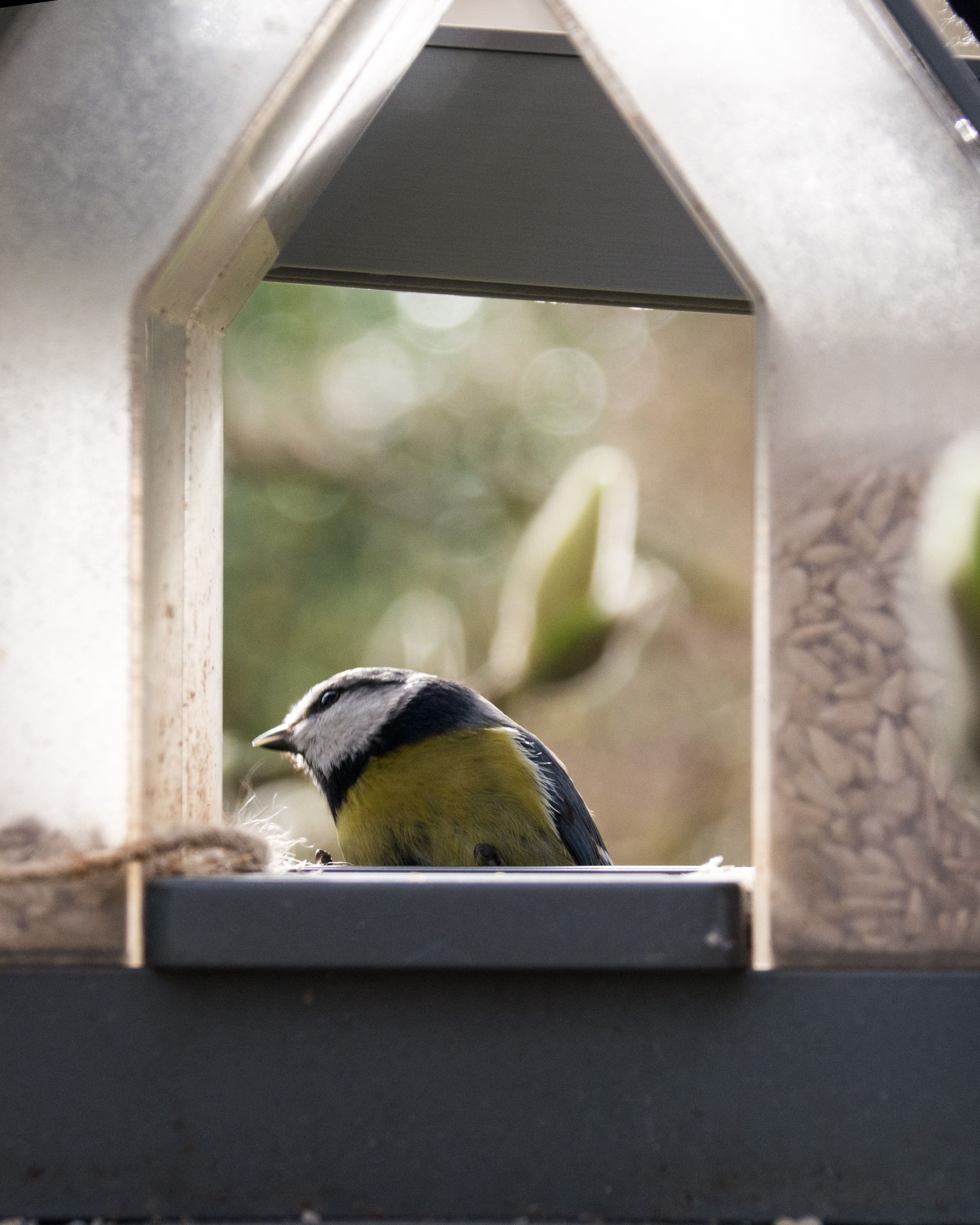
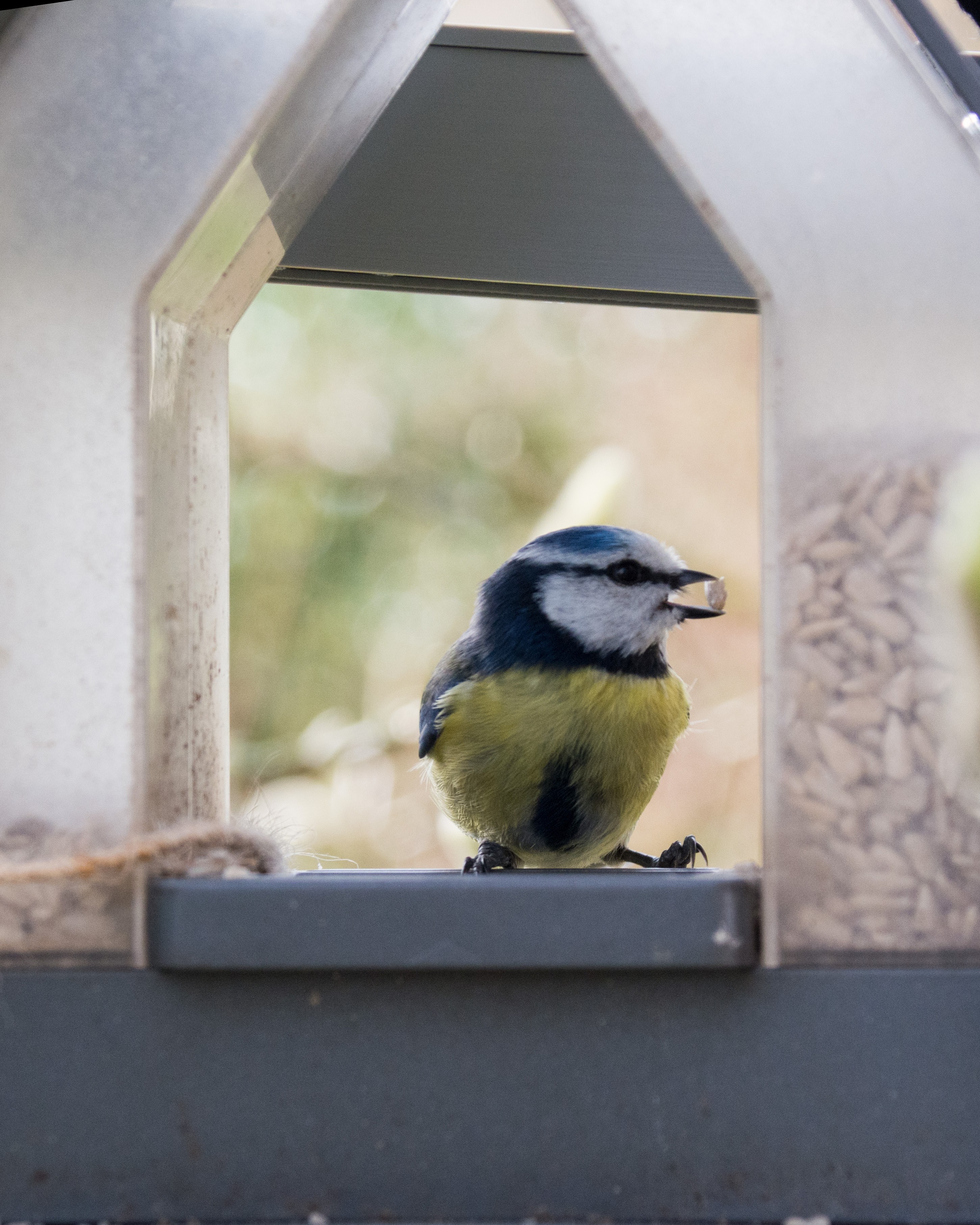
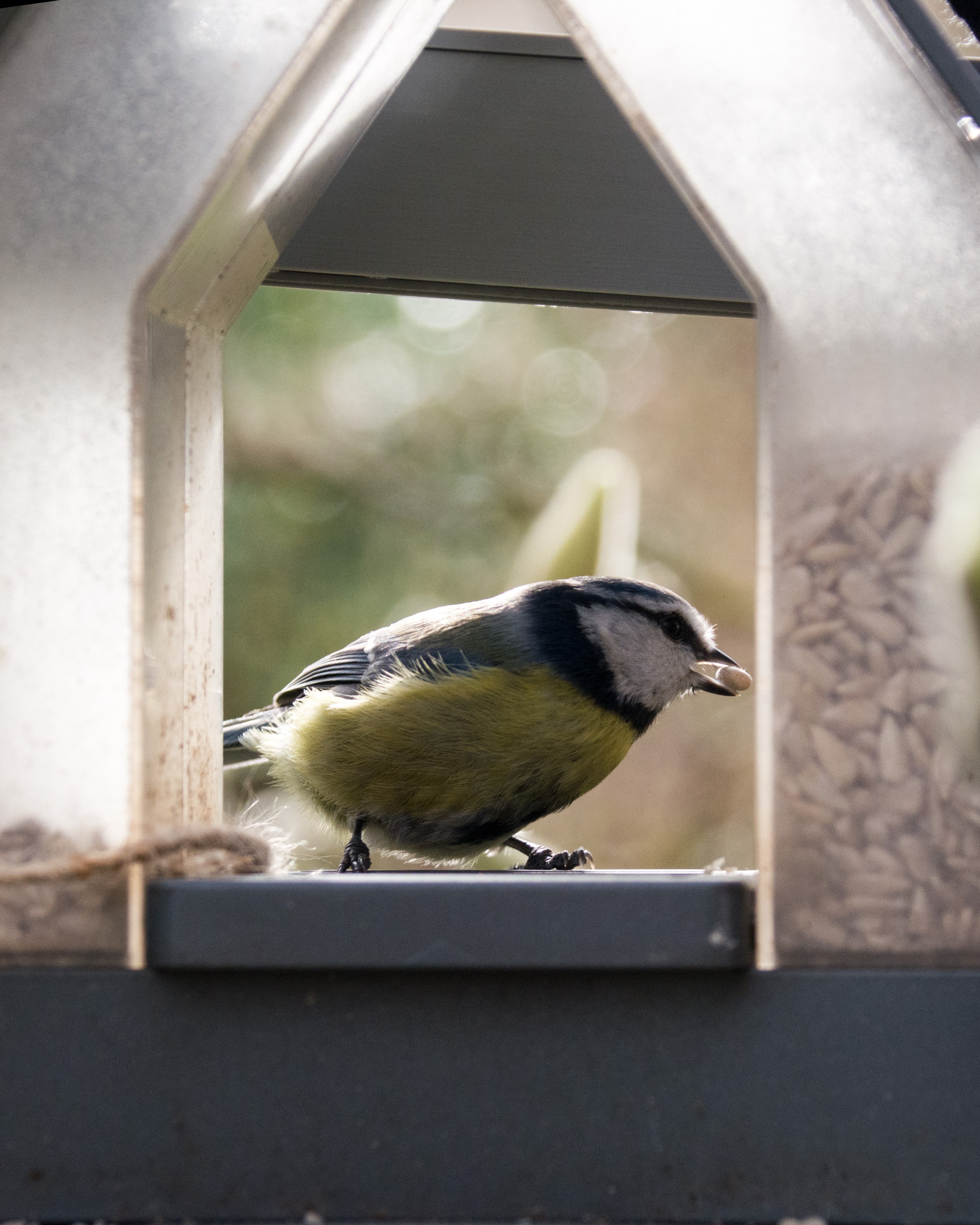
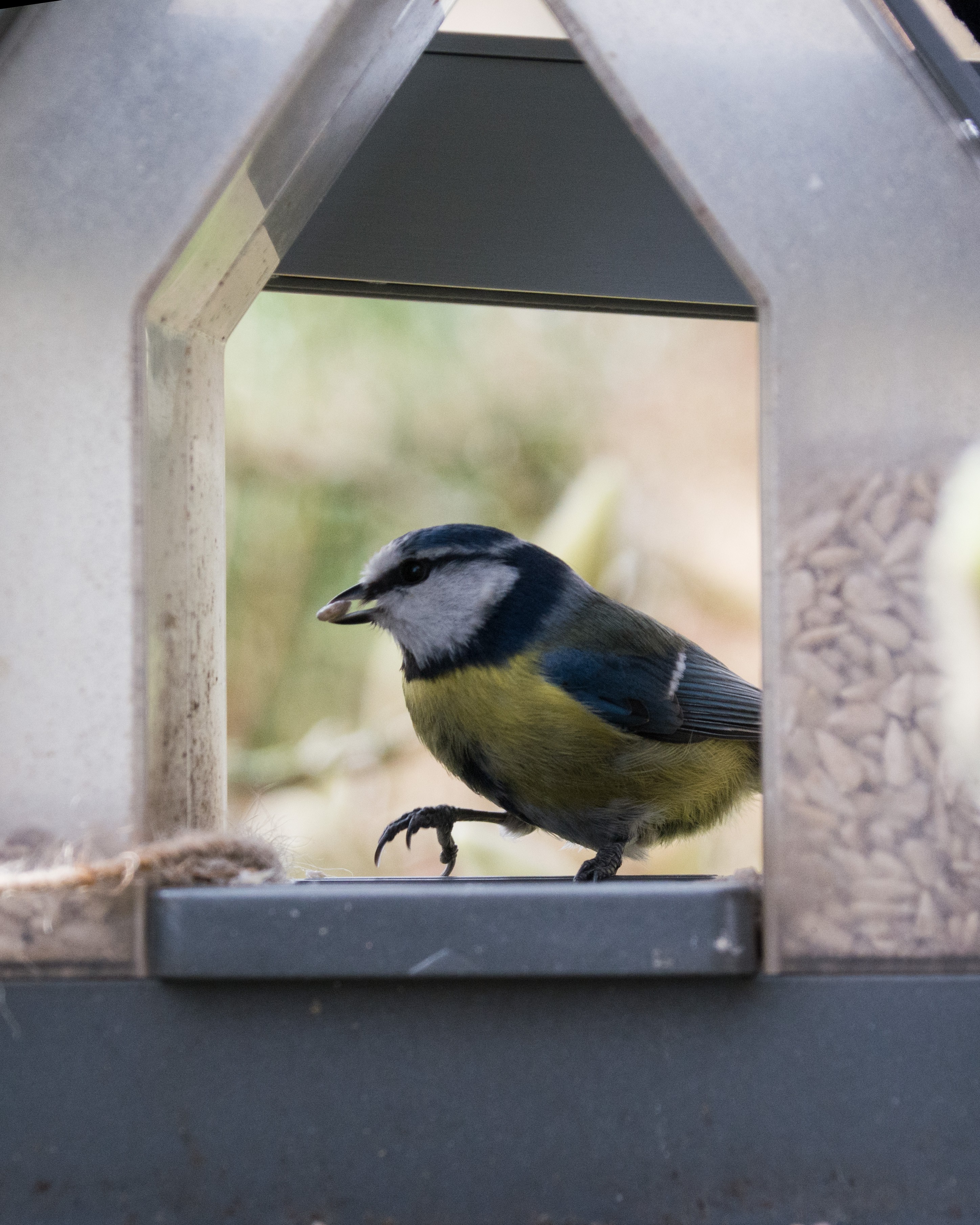
Happy Easter Photoshooting
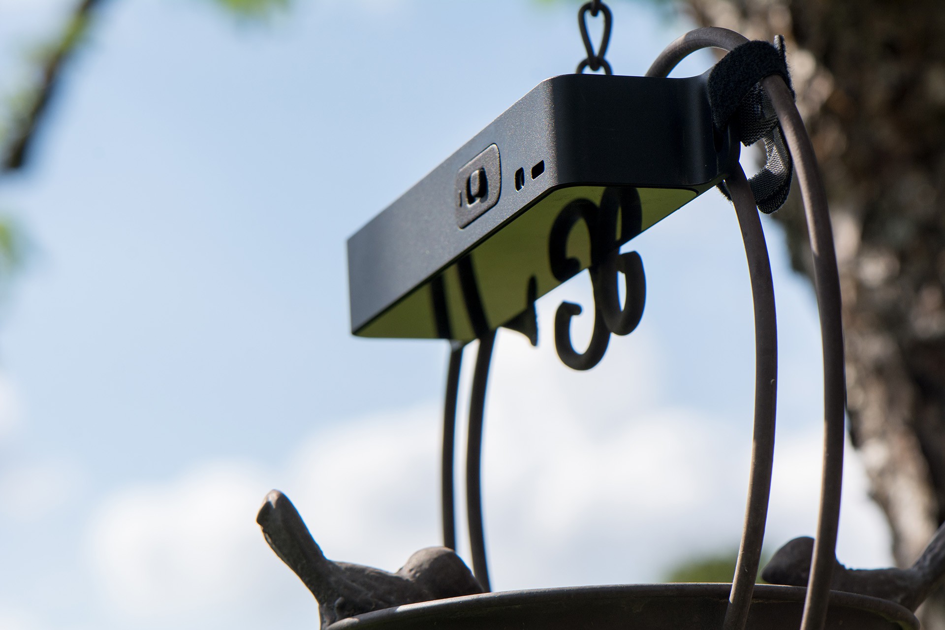
04/01/2024 at 08:12 • 0 commentsI took the RepTrap out for another round. I got 80+ Images of birds in total in 11h! I can't wait to use the new sensor version with the beautifull enclosure which will make it also much easier to attach the sensor somewhere. I used ropes and wires to attach it but it was terrible.
![]()
Lets talk about the camera settings!
I used my Nikon D7100 with a Sigma 18-300mm f/3.5-6.3. For the sensor and the camera to work nice and fast it is best to set everything to manual. The sensor does trigger the focus as well but in most cases it takes too long to take an image with. Also the shutter should be done as fast as possible to get nice and sharp images.
- Nikon D7100
- Sigma 18-300mm f/3.5-6.3
- I used ~170mm for a good compoistion
- aperture 6 to increase the focus area. I also tried 8 and 11.
One very nice feature of this sensor is the detection area which is like a wall! It basically represents the depth of field of the camera. You can set the focus of the camera to this exact "wall" and everything which will break the wall will get detected within the depth of field and end up sharply on the image later. I think that is a big plus.
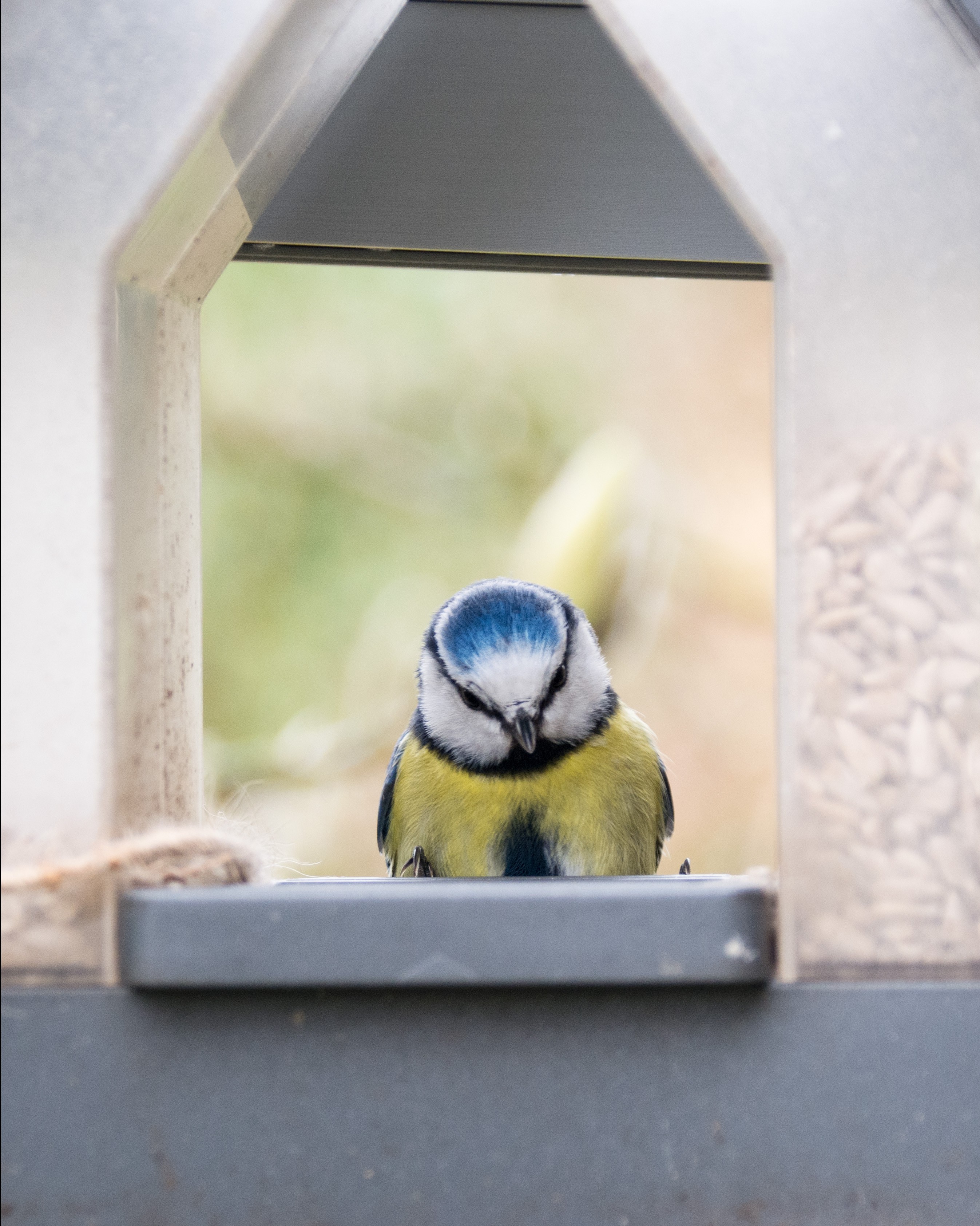
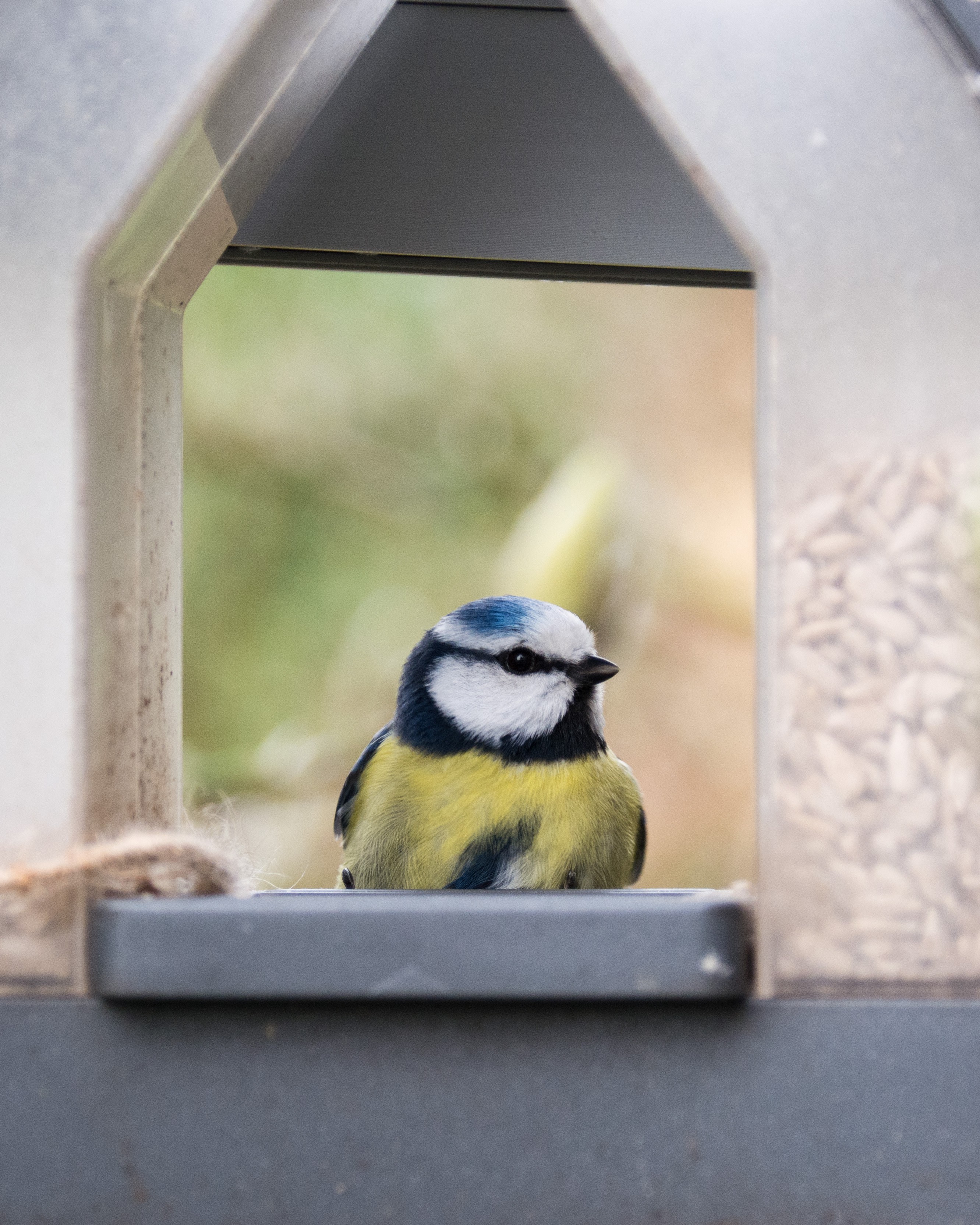
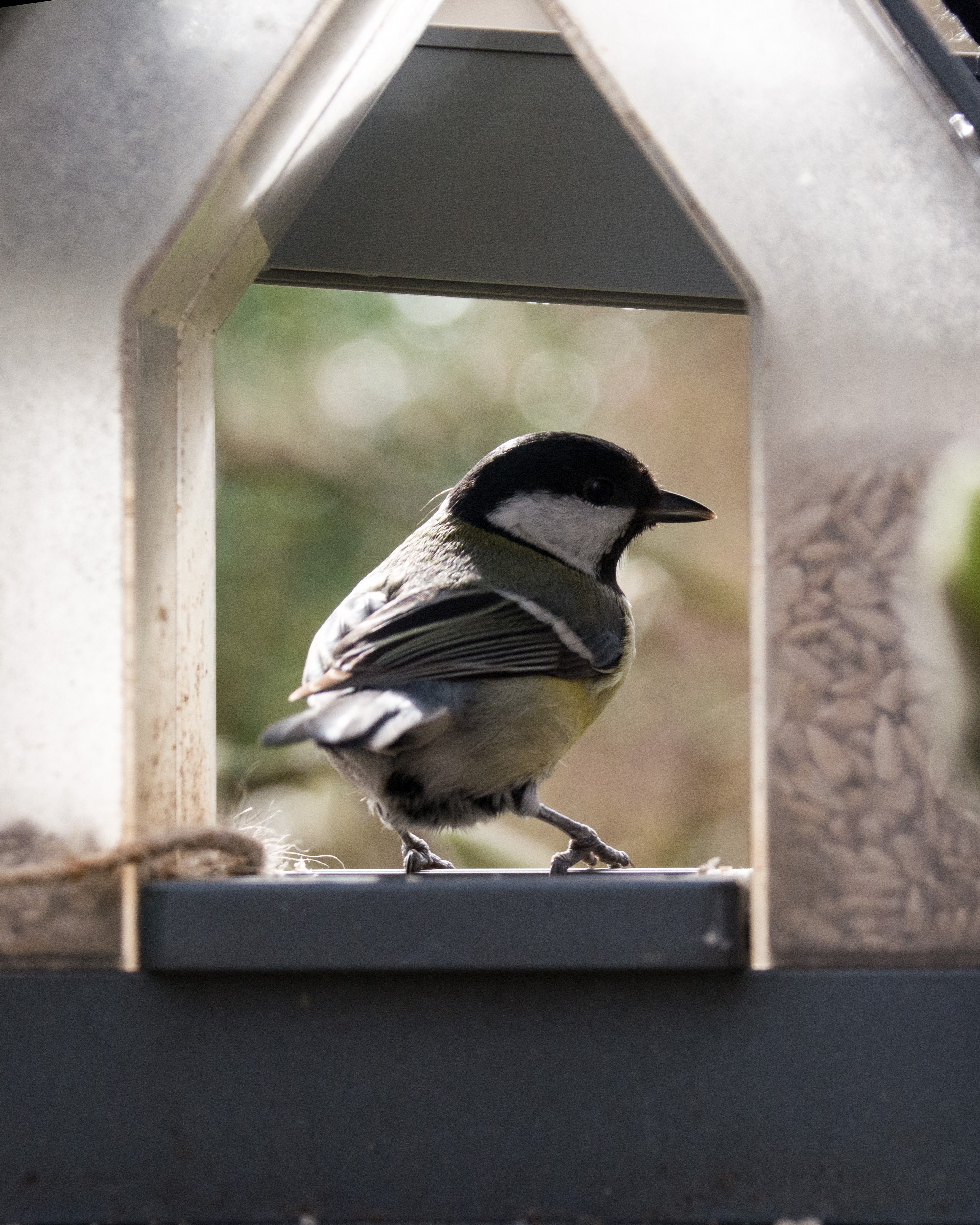
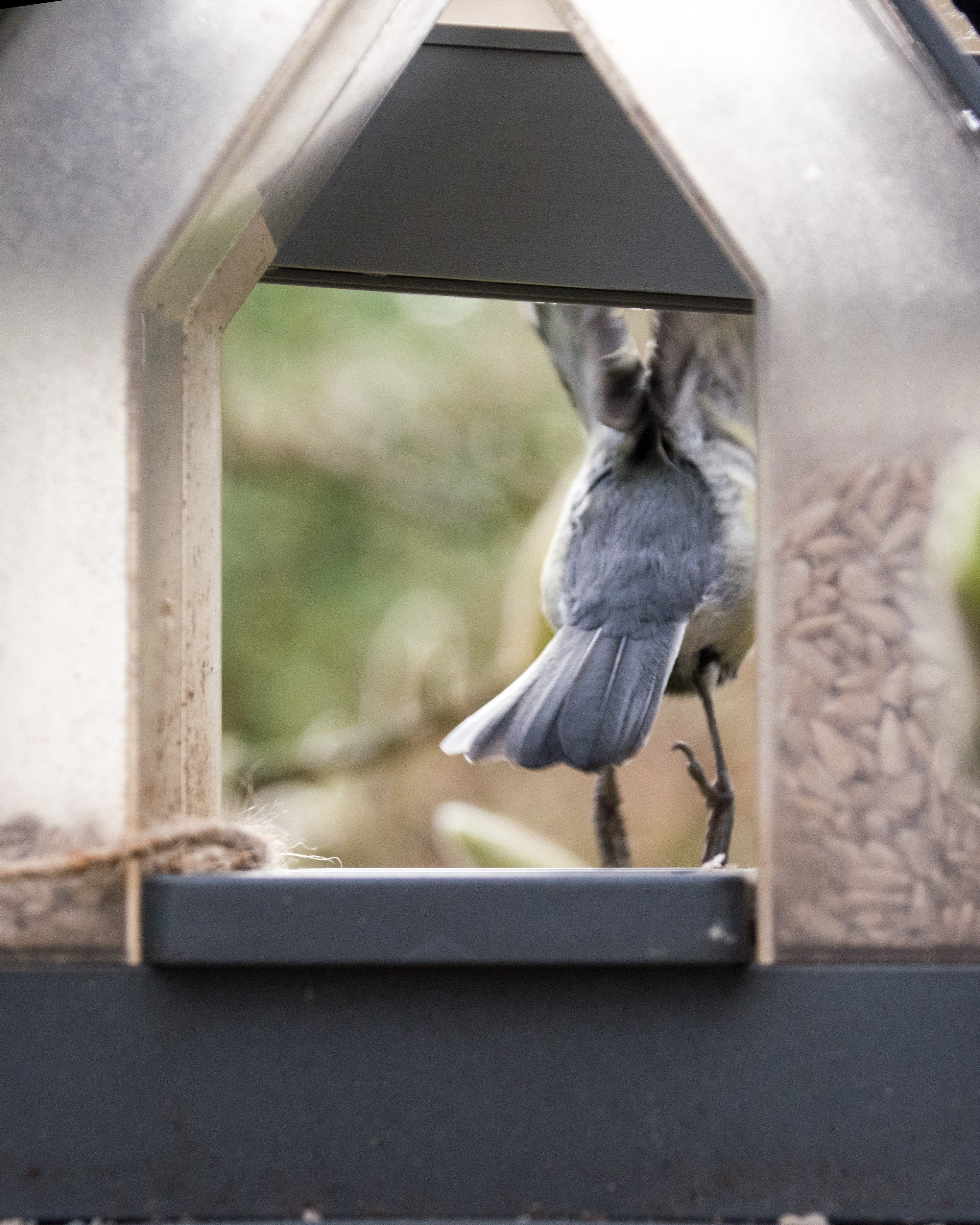
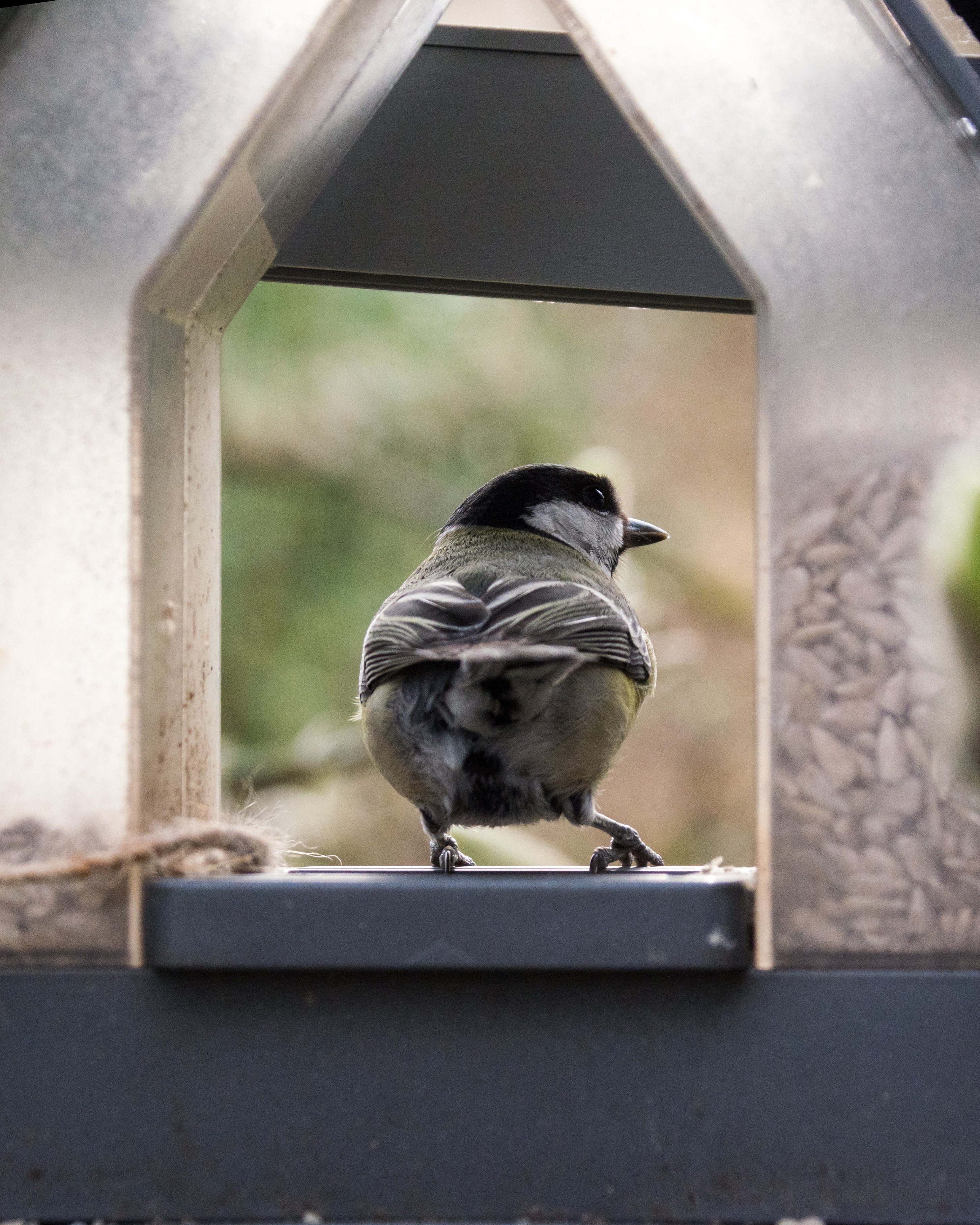
Here are some of my 80+ images I took
![]()
![]()
![]()
![]()
![]()
![]()
![]()
![]()
![]()
-
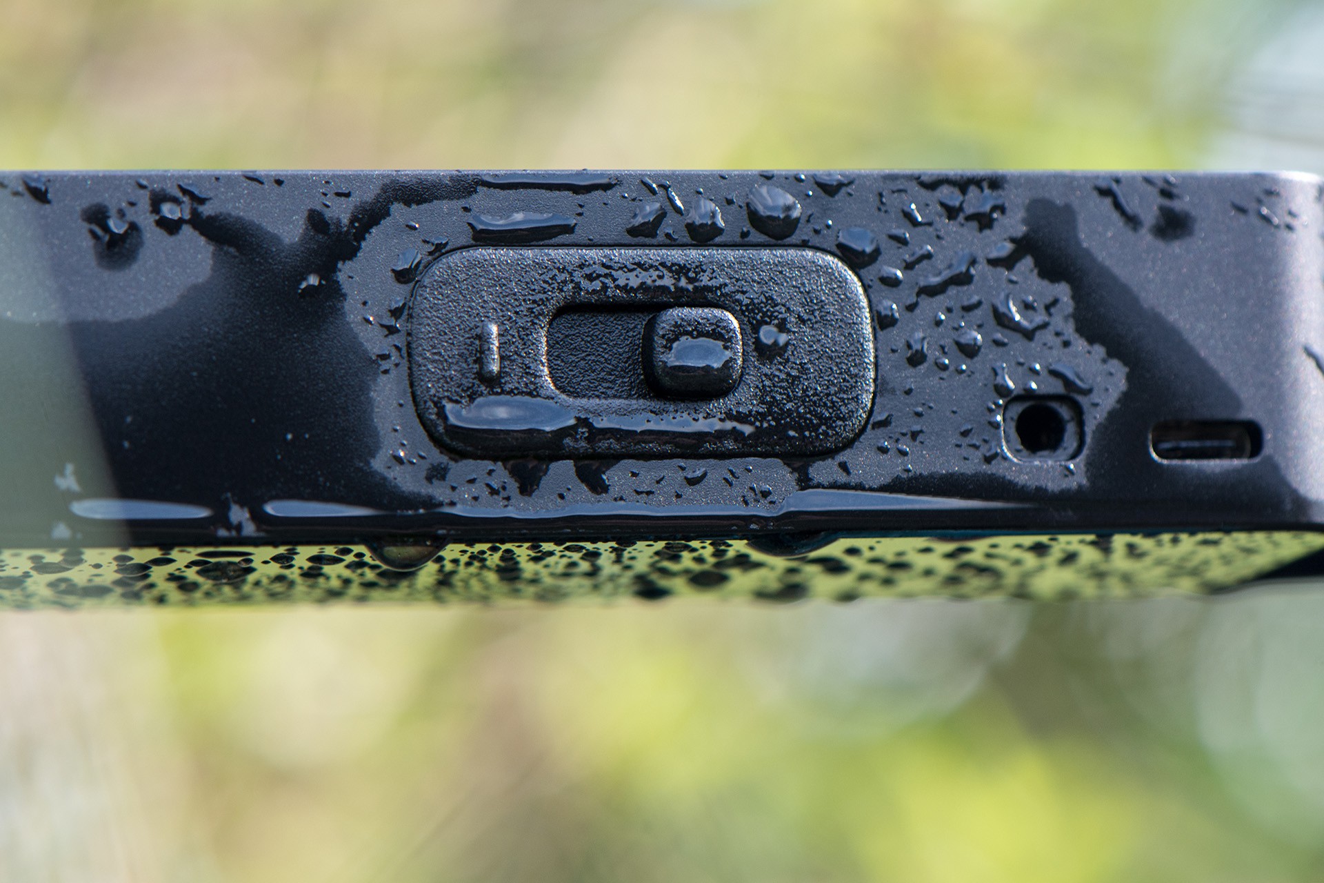
The waterproof magnet-switch
03/18/2024 at 11:35 • 0 commentsFor my project, I sought switches or buttons to control the device's power while ensuring its protection against moisture in wet conditions. Despite my efforts to find IP68-rated switches and buttons, I encountered a challenge: the available options were either prohibitively expensive or excessively bulky, designed to handle amperage far beyond the requirements of my project. After several hours of research, my disappointment mounted, leading me to explore alternative solutions. That's when I discovered the DRV5032 digital switch.
The DRV5032 sensor is capable of detecting the presence of a magnet and toggling its output accordingly. It presented the ideal solution. Moreover, the DRV5032 is known for its extreme low power consumption, which perfectly suited the energy-efficient demands of my project. However, I faced a new question: how could I integrate a switch on the exterior of my device that not only functioned like a traditional switch but also housed the magnet internally, while maintaining aesthetic and tactile qualities?
Turning to my friend Fabian from Formfjord for assistance, I tasked him with designing the enclosure and devising a method to incorporate the magnet seamlessly into a switch-like interface. Initially, he proposed two concepts: a circular switch and a ball switch (refer to images below).

Ball Switch 
Circular Switch The challenge lay in relocating the magnet away from the sensor to prevent detection while also incorporating haptic feedback into the switch. Neither of the initial solutions appealed to us. The circular design was too large, and we struggled to conceptualize how the ball-switch could function or provide the desired tactile sensation.
Fabian then proposed a novel concept: a conventional switch supplemented with two additional magnets to provide haptic feedback.
![]()
The light grey component represents the switch, while the green component denotes the magnet, which moves along with the switch. The red circles depict the two additional magnets that are attracted by the green magnet to generate haptic feedback. While this solution seemed promising, I harbored concerns that the sensor might inadvertently detect one of the red magnets permanently.
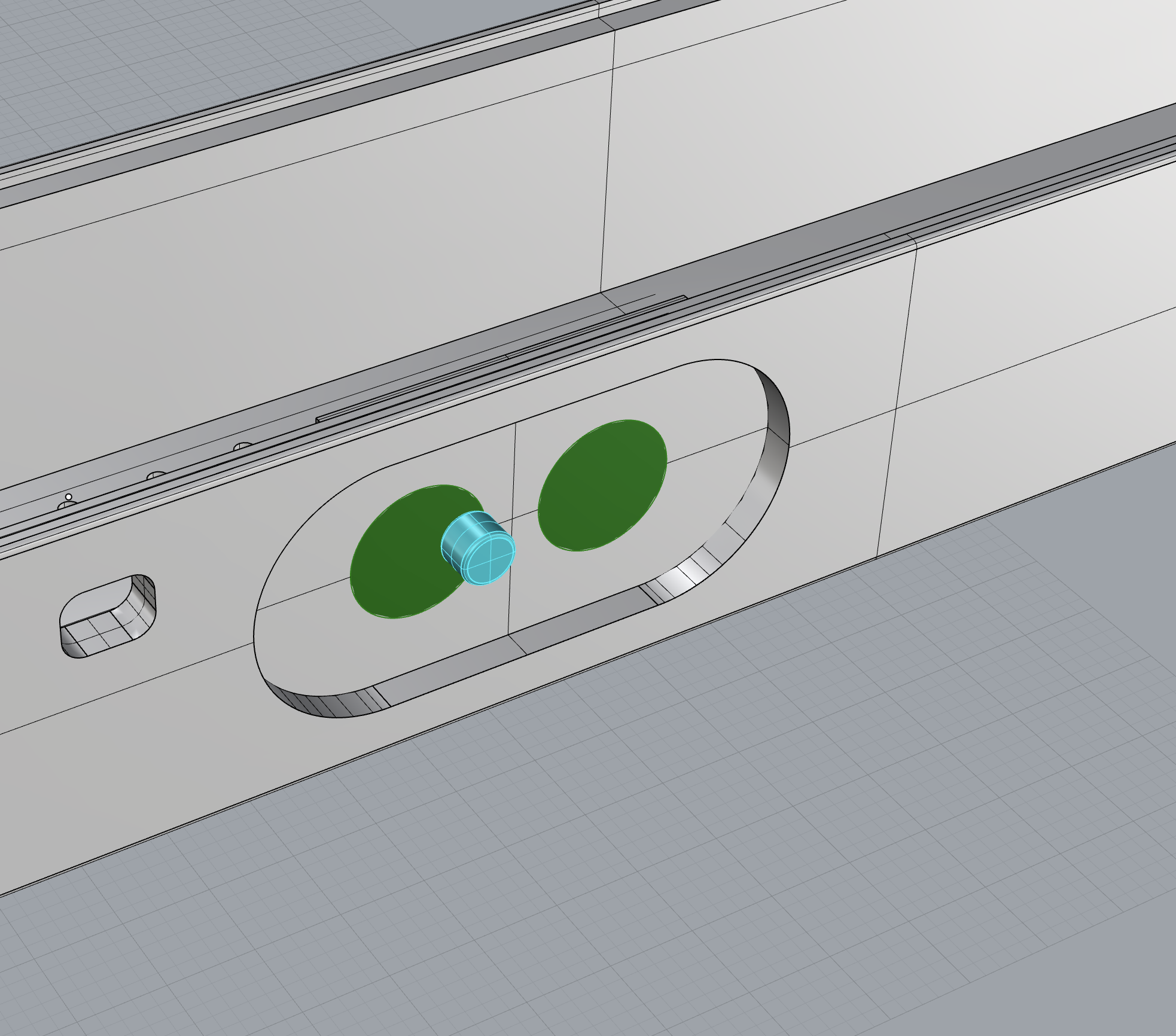
Then, an idea struck me: why not incorporate small metal plates on the left and right sides behind the switch? This design would enable the switch and the moving magnet to snap into position, potentially preventing the sensor from registering the metal plates as magnetic fields. With this in mind, we developed the following solution:
![]()
The green part are the two metal plates and the blue part represents the magnet.
![]()
With this concept in mind, we proceeded to create a preliminary prototype through 3D printing for testing purposes. The prototype comprises five components: the main enclosure with its insets, the movable switch part housing the magnet, a switch shell part designed to be affixed onto the enclosure to secure the movable component in place, and the metal plates for snapping into position. The resulting prototype appears as follows:
Conclusion
Despite the need for some fine-tuning, this solution has proven to be exceptionally effective! It offers a tactile sensation akin to a traditional switch while maintaining complete waterproofing, as there is no penetration into the enclosure. Moreover, the cost-effectiveness of the components is remarkable: the sensor costs approximately $1, the 3D printing process is straightforward and affordable, and the metal plates and magnet amount to just a few cents.
-
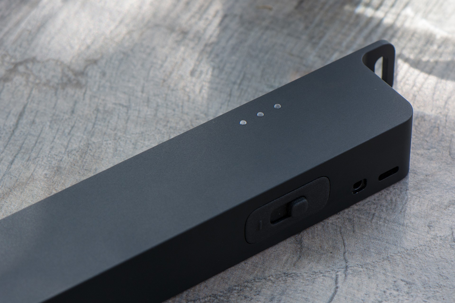
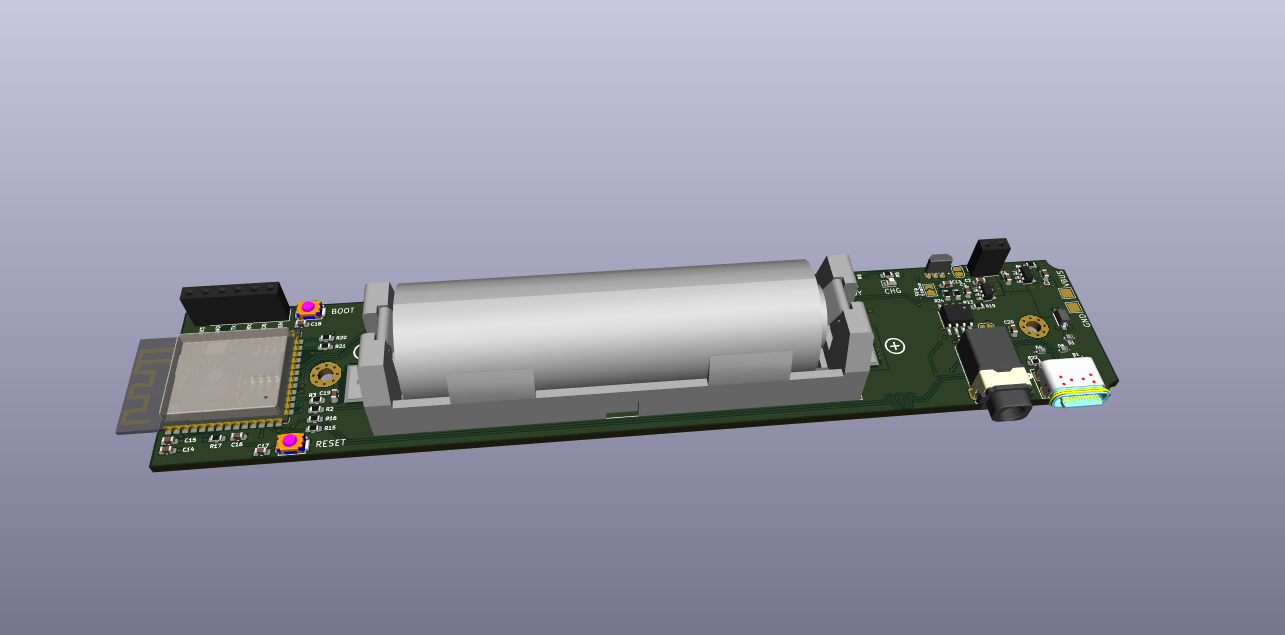
RepTrap ESP32-S3 Variant
02/12/2024 at 10:57 • 4 commentsI decided that I do not like the RP2040 anymore and exchanged it for the ESP32-S3. With the ESP32 I get BLE for this device, which can make it into a remote trigger as well but mainly it will be possible to set configurations for the sensors sensitivity!
The power consumption of the ESP is also lower in deep-sleep where I was not able to get the RP2040 into a very nice deep-sleep tho. Another benefit is the OTA functionallity I am getting which makes the device updateble very easy.
I also added a USB Detect to see if a USB is connected or not, that way I can handle the code differently for examply only start BLE advertising if USB is connected or checking for a specific WiFi to download firmware updates.
I also fixed all issues I found with the first Version, moved all connectors to one side to make it easier to be added into an enclosure, I added mounting holes to secure the PCB and I even left some space to add another output to be triggered which could trigger two different cameras at the same time. The connectors are now also on the horizontal sides of the board to free the short side of the device for mounting options like holes on the enclosure etc.
Another very experimental change was a Hall effect sensor DRV5032FB as a switch for the device! I want to achieve a IP68 waterproofnes with this device (I also exchanged the USB and the other connector to be IP68). The idea is instead of a classic switch or push-button which needs a hole in the enclosure I add a hall sensors and put a mechanical switch from the outside including a magnet. It hopefully will feel like a real switch but has no contact to the PCB - that way this switch will be 100% waterproof! and the only gaps I have are for the USB and klinken connector. Lets see how that idea works out.
The device also got a RGB LED to show its different states it can be in or show errors. The USB Port is also connected to the ESP32 USB which can be benefitial later.
If you read this please comment +1
-
Looking for support
10/12/2023 at 07:14 • 0 commentsHello there!
I'm conducting research to gauge the level of interest in this project. To achieve this, I'm in the process of gathering email addresses to compile a list. This list will help me maintain an overview of individuals who are interested and whom I can also directly update on project status.
If you'd like to support the project and stay informed, please consider adding your email address to the list by visiting this link: https://www.open-things.de/thing-2.html#subscribe
Thank you for your interest and support!
-
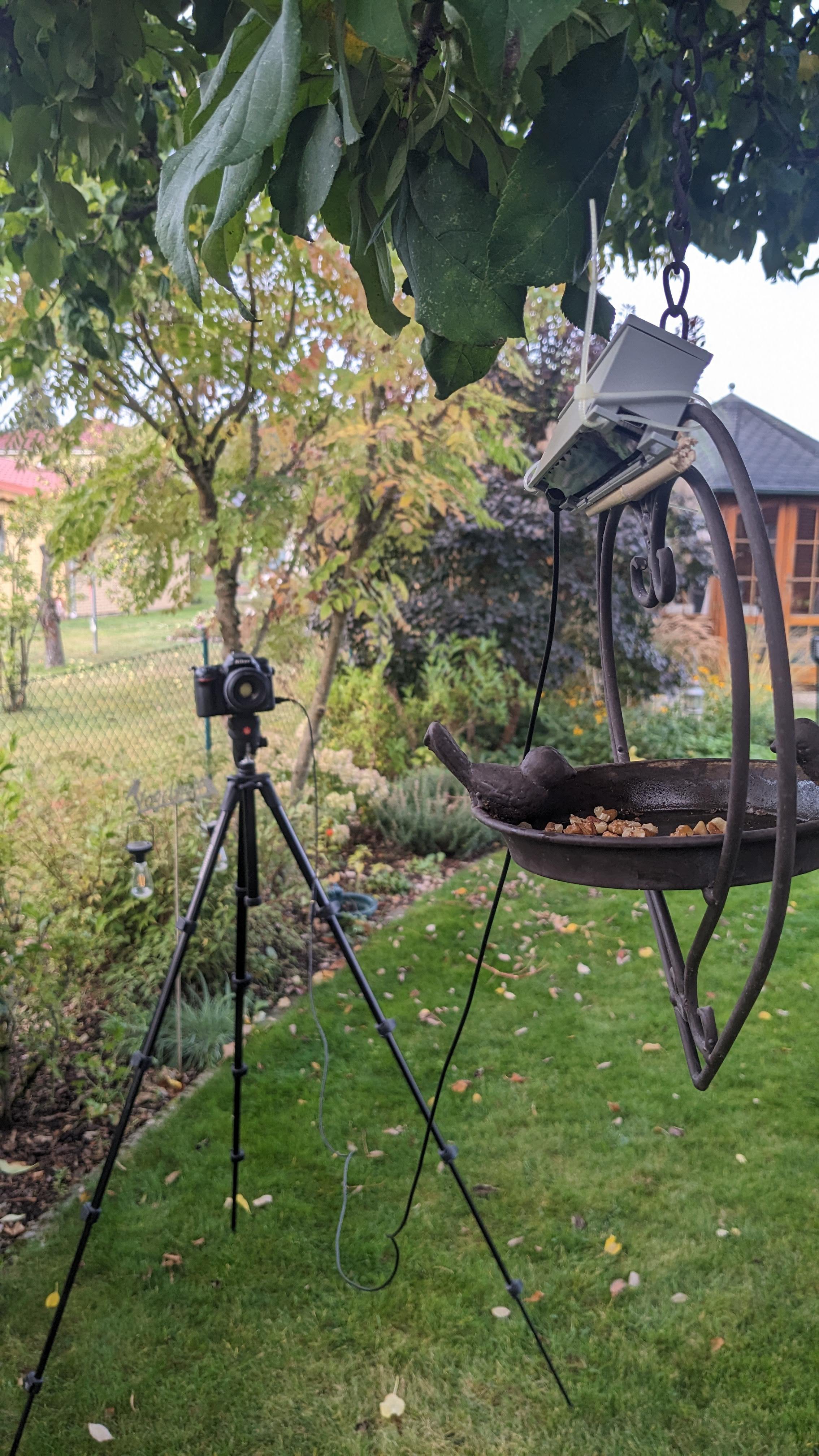
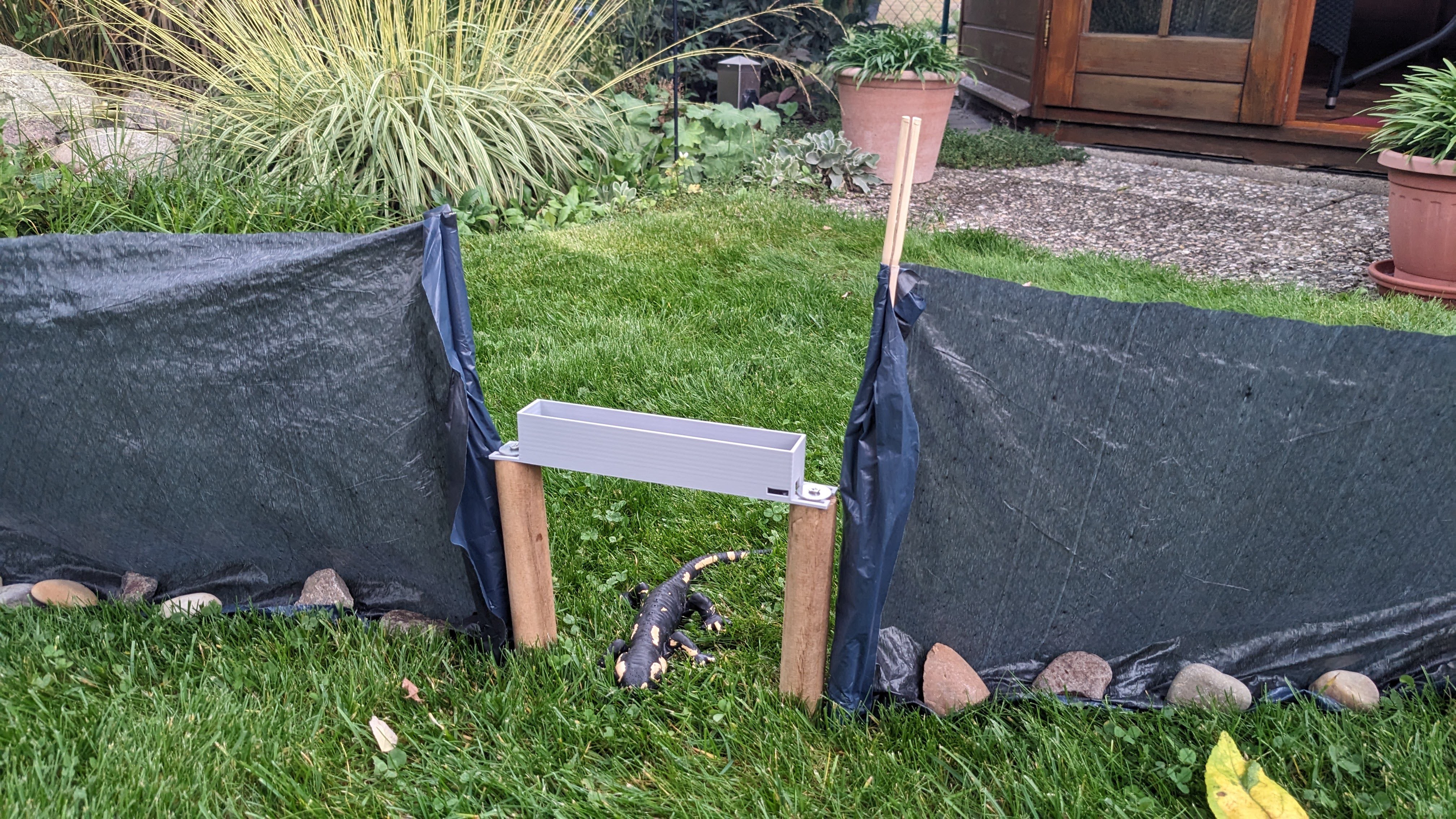
Field Test
10/08/2023 at 07:58 • 0 commentsLast week I printed a smaller case for the RepTrap and tried to set it up how it should be setup. Unluckily I did not catch any animals with it. I tried to set it up to catch some birds because they are more likely to appear, but had no luck. I witnessed some birds approaching the bait but I think they have been just scared due to the camera and the sensor. They have been close and one should have been inside the field of view but was to quick. It actually needs some time for the sensor to detect an object, the settings are 80ms measurment and 100ms sleep (which is already pretty fast and not very battery friendly) my initial setting was 100ms measurment and 300ms sleep. It is getting cold already outside and so there are not many animals to be photographed.
But here are some images of the setups

The sensor can be setup to monitor the entrance to a home ![]()
Also bird watching can be managed with it but this little guys are super fast! ![]()
LOOK! A LIZARD... yea okay.. it is a fake one. One day my friend! one day! -
Prototype Adventure
08/15/2023 at 14:39 • 0 commentsI received all components including the 0402 parts (which I never soldered before) and on Monday I also received the PCB (made by Aisler).. so it was time to test my soldering skills and eyesight.
Spoiler: both are crap! But I made it! After a couple of houres I got the first prototype of my RepTrap in my hands. I will let the images and video talk for themself. Second spoiler: it was working on the FIRST try! (almost)


and it is PUNCHING FAST!
Mistakes I made (of course there are some)
- forgot to add pull-down for the LDO enable pin
- connected the status LED to BATT+ instead of VBUS (which made them glimming even if the edvice was off)
- the optocouple was not working with the 220R I added to prevent to much current to flow. But somehow even 100R did not trigger the camera... I removed them and then it fully opened the coupler. Not sure if that is the right way.
- the 18650 Battery Holder was made for the extended version of an 18650 incl. protection circuit but I don't have such a battery and also realised that they are super expensive.
Everything was fixable! and now it already works super nicely! But now I have to do some more coding.. but I am very proud of that thing. I hope I can test it soon in the real world to see if it really does what it is supposed to do! Stay tuned
Openthing 2 - RepTrap
Openthing 2 RepTrap is a detection device and camera trigger for capturing images of relatively small animals, including lizards, frogs etc.