-
LT3751 DC DC Converter - 12 V to 245 V!
05/19/2024 at 15:25 • 0 commentsWorking on the custom DC to DC converter. I made an EVB for the LT3751. This board will take 12V from the battery, and convert to 245V to charge up the high voltage battery in the Camry.
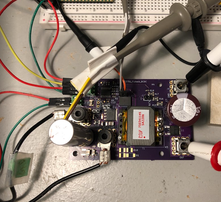
Here is the board built up on the bench. The main inductor is a Wurth 750341145, and the transistor is a SIJH5800E-T1-GE3. I set the maximum current to 2A using a 0.05 Ohm sense resistor. The feedback to set the output was 3, 200k 1206 resistors in series, and then the divider resistor was 3k to ground (i.e., 245 V * 3k / 603k is 1.21 V). The high voltage rectifier was a wolfspeed silicon carbide C3D04060E.
![]()
Because the transformer is only 1:5, the VDS expected is approximately 12V + (245V / 5) or 61 V at the highest during the switching. I'm going to look at the Wurth 750310355 transformer (1:10) so the max VDS isn't so high.
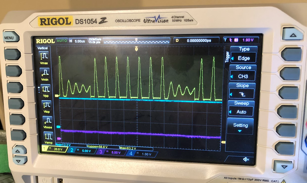
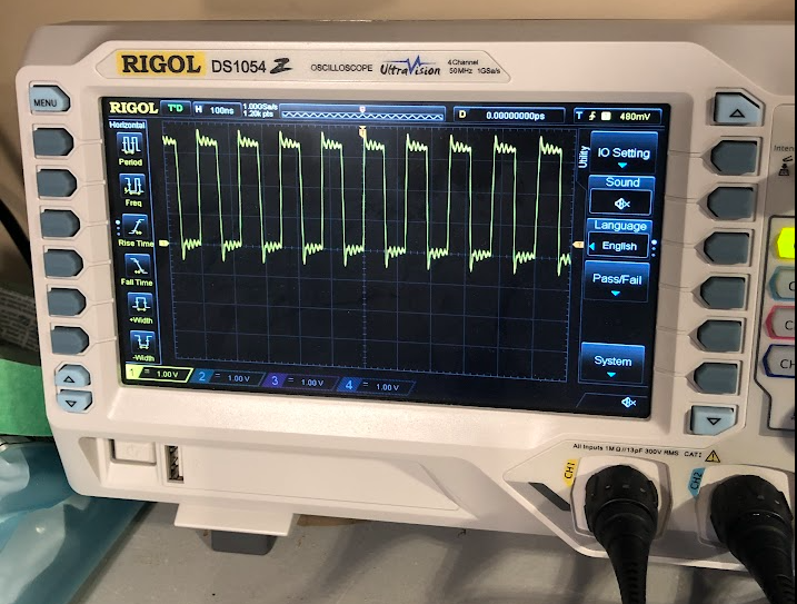
Here are a few traces on the scope. Ch1 (yellow top) is the VDS. It reaches up to ~63.2V. The input 12V seems to be holding up monitored on Ch2 (blue, middle), and the fault seems to be okay on ch3 (purple, bottom).
![]()
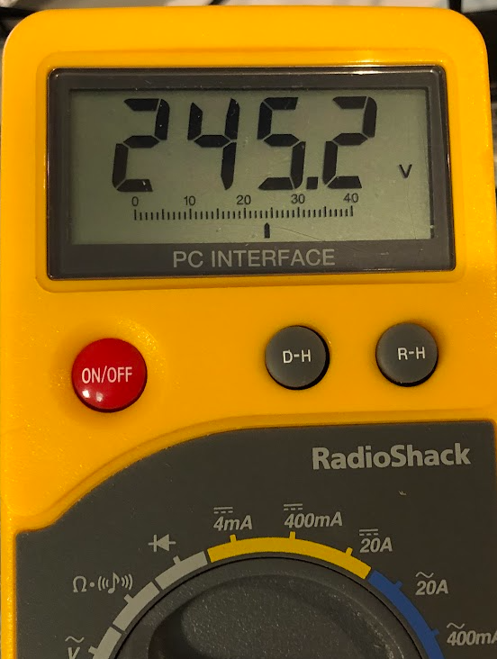
Lastly, the basic DC meter at the output, 245 V! Yippee.
![]()
-
Home Electrical Transfer Switch
05/17/2024 at 20:46 • 0 commentsIn order to power my place, I installed a transfer switch. I went with the Reliance Controls 310CRKNC from Costco. Below is what I did. This is for information only - always consult an electrician/have inspections done/etc.
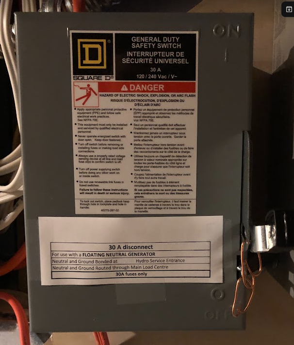
First, I installed the 30A inlet box for outdoors. Drilled a hole in the wall, and secured the wiring in the box. Note the "floating neutral" sticker. The neutral and ground are ultimately connected together at my service entrance, so I configured my generator as "floating neutral".
![]()
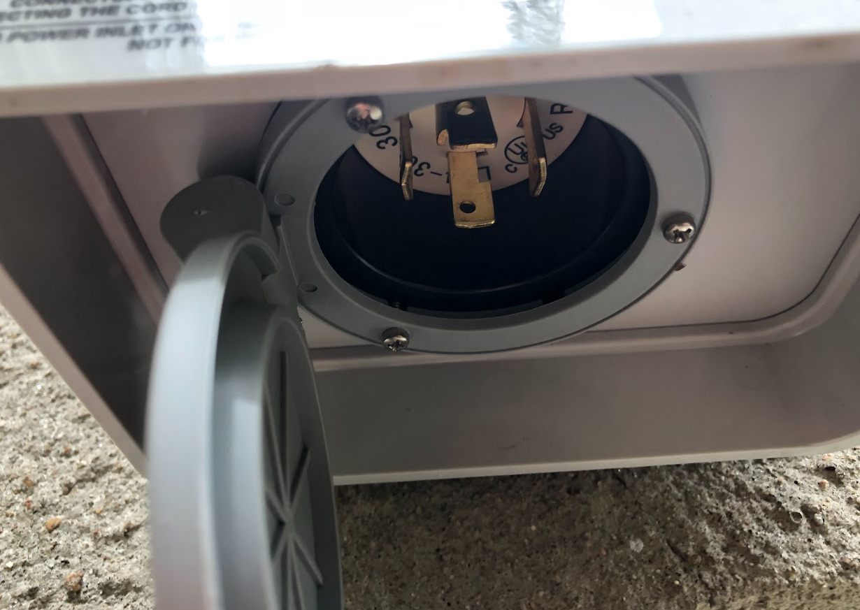
The receptacle is actually underneath, with a little cover.
![]()
For inside the house, I brought the wiring into a disconnect switch. This is over and above local code, but it made for a nice demarcation for how the lines, ground, and neutral are connected.
![]()
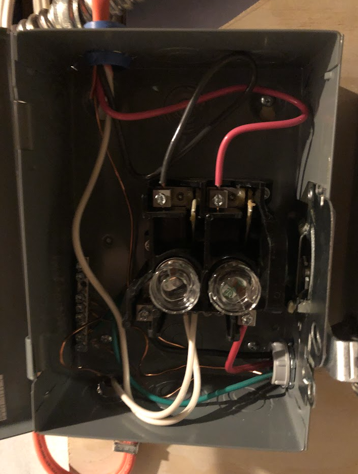
Inside the disconnect box, the generator wires are at the top. The two "lines" go to the 30A fuses, the ground goes to the ground bar, and the neutral goes to the isolated neutral bar. The ground and neutral go back to the main panel, and ultimately to the service entrance where they are connected together at the one point. The two lines and ground go to the transfer switch on the right.
![]()
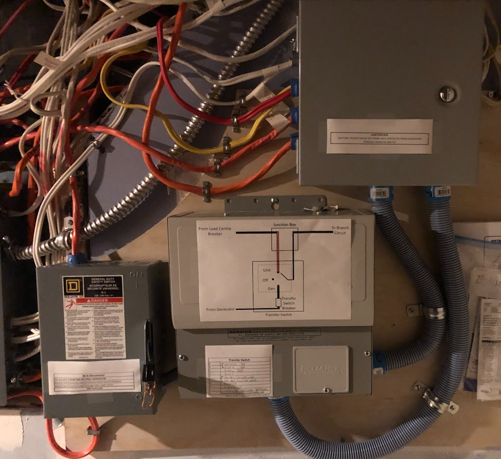
The Canadian Electrical Code is a little different than the US, so I can't make the transfer switch connections inside the main load center. So, I used a giant junction box (BUD industries JBH-4960-KO) to bring the connections for each circuit to the transfer switch.
Below is a picture. The generator power comes from the disconnect at the bottom left. Each of the breakers from the main load center go into the junction box (connected to the "red" wires from the transfer switch). Then, you go through the transfer switch, back to the giant box (the "black wires" from the transfer switch), and then out to the branch circuits. I put a sticker on the giant junction box indicating power is fed from potentially two locations.
I used two whips - one for the "red" wires, and one for the "black" wires, to keep things easier to manage. The transfer switch comes with a metallic whip, but the carlon nonmetallic is little easier to flex.
![]()
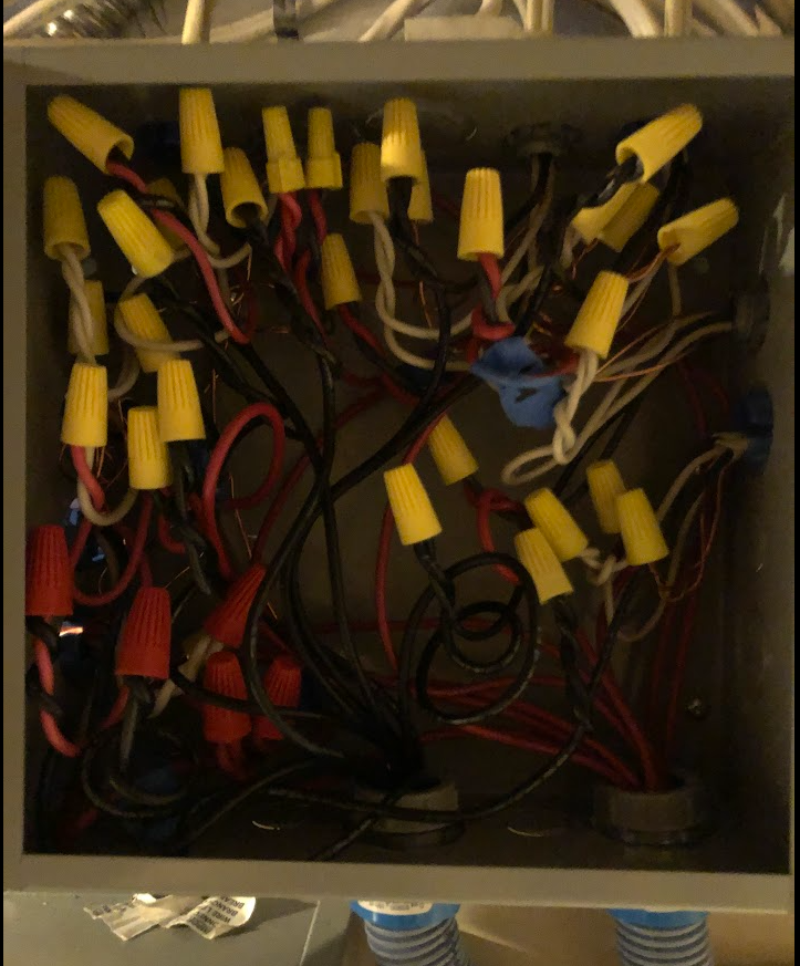
Inside the junction box, it is a little busy, but manageable. I got the whole thing inspected too - joy!
![]()
-
Half Bridge Driver
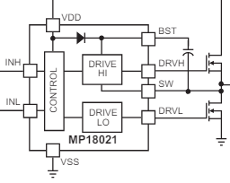
04/25/2024 at 03:22 • 0 commentsBuilt a half-bridge driver based on the MPS MP18021. I like the MP18021 because the SW pin is tough. It can go to -5 V, in case there is something pulling down the switch voltage. Also, it has the diode built in for the VDD to BST path, so that saves a part.
![]()
![]()
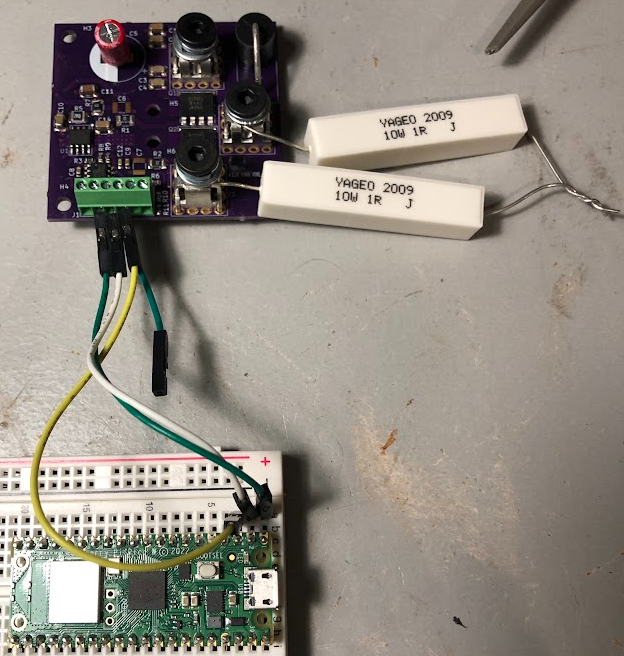
I drove the INH and INL from a raspberry pi pico (PIO programmed), and tested it with 2 Ohms of resistance. The 8x8 powerpak transistors have quite a lot of gate capacitance, so you can drive a few hundred kHz, but beyond that the MP18021 starts getting kind of warm. A few MHz and it will go into thermal shutdown.
I am debating a full bridge versus a flyback design for the DC/DC converter, and I think I'll probably go with the flyback, but building the half bridge is kind of fun since you can re-purpose them for other projects like motor drivers. At the bottom was a TC620CVOA for checking the board temperature, and that worked as expected. It is a super simple chip - if the temperature passes a setpoint, it outputs a voltage. That is the third wire going to the raspberry pi pico for monitoring (the TC620VCOA is powered from 12 V, so there is a voltage divider at the output to match with the 3.3V of the pico).
-
High Current Isolated Switch
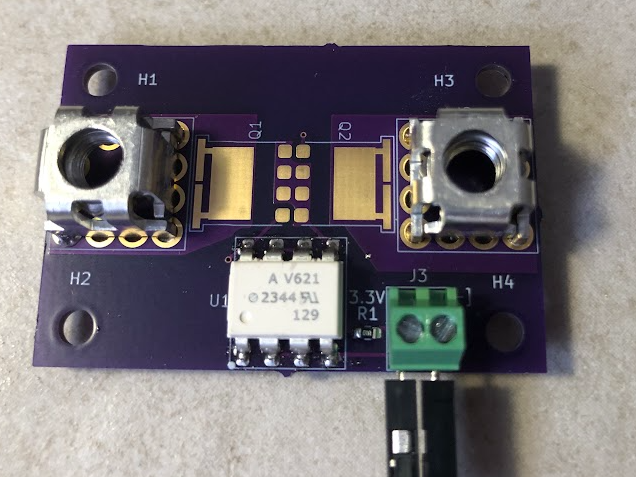
04/08/2024 at 03:11 • 0 commentsI wanted to build a high current isolated switch, and also test the footprints for the switching mosfet (Vishay SQJQ130EL, 445 amps) and the Wurth S93513 press fit screw terminal (192 amps).
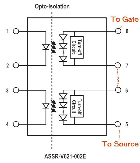
It is based on a Broadcom ASSR-V621 dual channel photovoltaic MOSFET driver. You bias the LED on one side of the driver package, and on the other, the photodiodes generate ~7 V for the mosfet gate source voltage. In my circuit, I chained together the photodiodes so that you get ~14 V for Vgs, to reduce the on-state resistance.
![]()
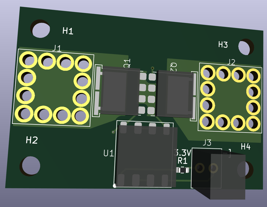
The mosfets are placed source-to-source to prevent the source-drain diodes from conducting.
![]()
Here is a photo of the board with no mosfets (to double check the polarity of the gate voltage, and check the fit on the press terminals).
![]()
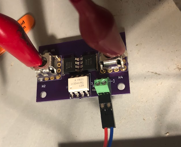
Here is the board with the mosfets populated...
![]()
With the 3.3 V applied to the one side of the switch board, and 2 k resistor to ground, I measured the delay/rise time to turn on the fets. At about 7 ms, and an expect capacitance of 40 nF for the mosfets, this is about right.
![]()
Turn off time was about 262 us, which was a little better than expected.
![]()
-
Code for the raspberry PI pico, AMC130M03 evb
04/06/2024 at 20:08 • 0 commentsI have posted the code for the raspberry pi pico that interfaces with the AMC130M03 evb. Please see github.
-
High Voltage Isolated ADC - AMC130M03 - Alive!
04/06/2024 at 02:54 • 0 commentsGot my AMC130M03 eval board from oshpark. Assembled the board and...yippee - it worked.
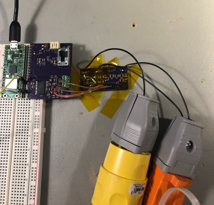
Here is the setup on the bench. I ran extension cords from walls plugs that were on different lines (i.e., L1 and L2) from my house mains. The extension cords plug into the resistor chain voltage divider. It has 5x100k resistors, and then 1k resistor to neutral (so, V_out = V_in * 1k/(1k + 500k)). The reduced voltages are fed to ADC0 and ADC1 of the AMC130M03.
![]()
The AMC130M03 has an isolated DC-DC converter that you feed a 8 MHz signal to. So, I created a PIO on the pico that outputs the 8 MHz tone.
![]()
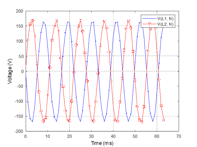
After programming the AMC130M03 through the SPI, I can then capture ADC samples every millisecond from the L1 and L2 voltages. From the ADC samples, you can calculate the actual voltage knowing the PGA gain of the AMC130M03, and the resistor divider, so you get the plot below.
![]()
Each line is ~170 V peak, and the two lines are out of phase as expected, joy!
So, now I can measure high voltages with an isolated ADC! The full scale range of the ADC is +/- 1.2 V, so +1.2 V with the voltage divider would be 601.2 V, so plenty of range for the Camry pack voltage (expected to be around 300 V).
-
Code for the Hall Effect Current Sensor
03/30/2024 at 18:04 • 0 commentsThe code for the hall effect current sensor has been posted on github. It is a micropython file for executing on a raspberry pi pico w.
The main idea of the code is that a timer executes every 1 millisecond. Each time the timer executes, it will take an ADC measurement.
There is a simple wireless webserver, so you put the sensor wherever you want, and then ask it to take some measurements, and then download them.
To ask it to take the measurements, you can use a browser and set the URL to ?GO_ADC?
![]()
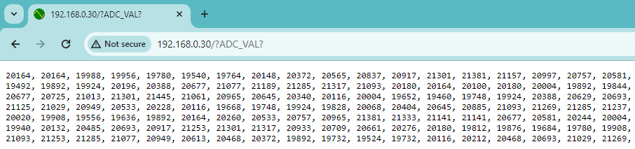
Then, you can get the measurements (256 samples, spaced at 1 millisecond) with ?ADC_VAL?
![]()
Then, you can copy and paste into your favorite plotting tool.
I also added a triggering function so that, when activated, it will start taking data if the ADC reading is above or below a threshold (you can ask for the values with ?TRIGGER_HIGH_SET? and ?TRIGGER_LOW_SET?, and set them, for example, with ?TRIGGER_HIGH_SET=25000TRIGGER_HIGH_SET?
The code also supports serving up webpages, pictures, etc. For example, I created "favicon.ico" (which is just a .png file called favicon.ico that is stored on the raspberry pi pico.
![]()
-
The $2 Hall Effect Current Meter is Alive, and can measure +/- 426 Amps
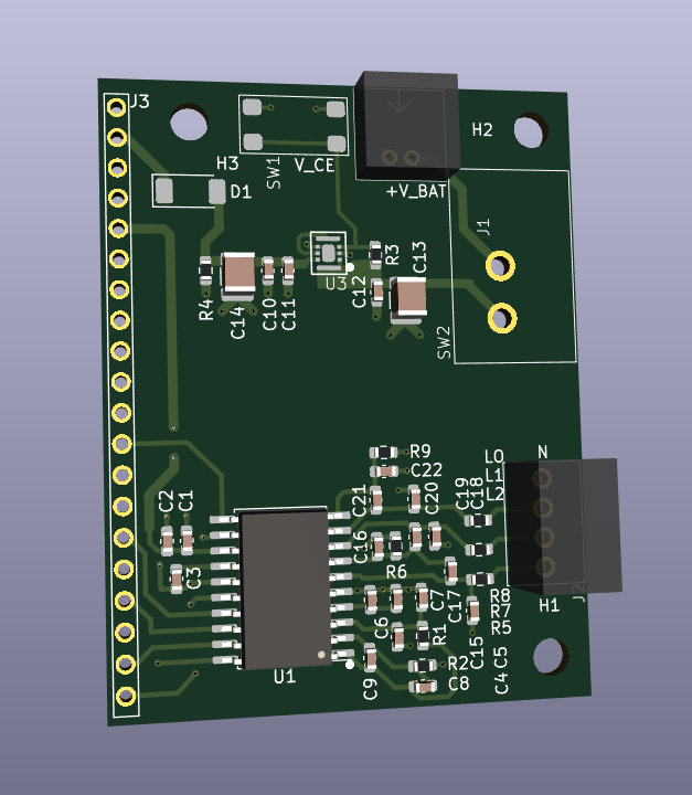
03/30/2024 at 17:48 • 0 commentsGot the hall effect current meter PCB back from OSHpark, tested it out on my AC mains, and it worked!
So, I wanted to be able to measure the current in the Camry and other parts cheaply, and without contact. TI makes a nice bipolar hall sensor with high bandwidth, TI DRV5053. So, I created a simple PCB and got it made at OSHpark.
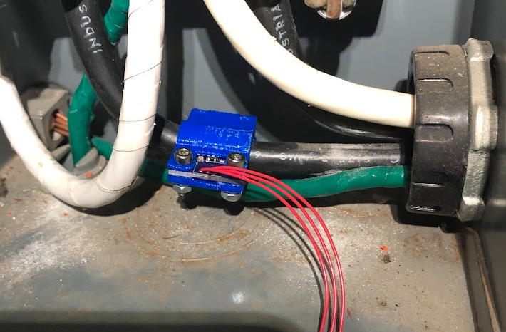
I assembled it and snapped it into a 3D printed holder, and clipped it next to my L1 mains line.
![]()
The hall effect sensor is held approximately 8 mm away from the center of the conductor. At that distance, 1 Amp in the wire will give rise to 2.61x10⁻⁵ T at the sensor. For an online magnetic field calculator, see Hyperphysics. The ADC was a raspberry pi pico, with a reading of 0-65536 from 0 to 3.3V. Luckily, the TI sensor will output 0 to 2 V, so within the range of 0 to 3.3 V. For no magnetic field, you get 1 V out of the sensor, for 2 V that means a magnetic field of 0.011 T, and for 0 V, that means a field of -0.011 T (sensor is bipolar). At 0.011 T, that would be a current ~426 Amps. Pretty good for a $2 sensor. :)
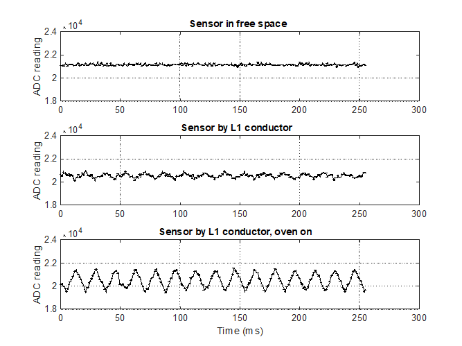
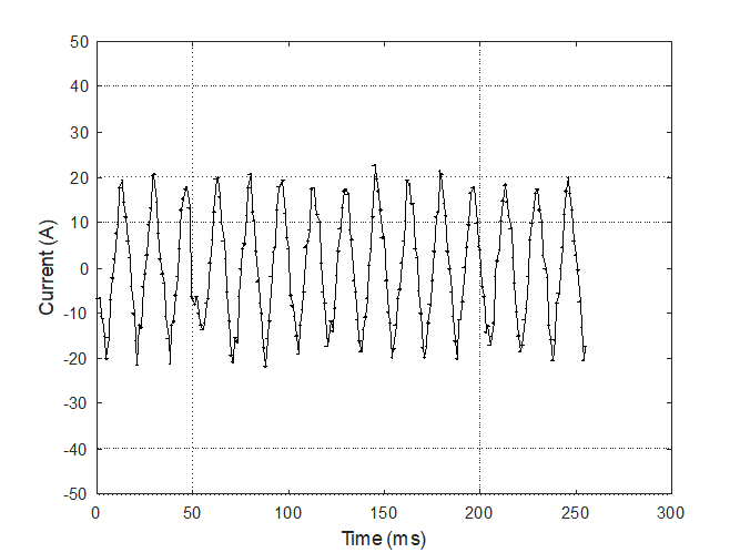
Here is a plot of the readings. The top figure shows the sensor reading for the sensor in free space. The raw ADC reading is about 21000 (i.e., 1V in). The next reading is the sensor by my mains L1 conductor, with the small background load of the house. The bottom graph is when I turned my oven on.
![]()
Converting raw ADC values back to Amps in the cable gives:
![]()
So, roughly 40 Amps peak to peak, or 20 Amps peak, or 14 Amps RMS. 14*240 = 3360 W, so pretty reasonable for the oven.
-
High Voltage, High Current Measurement
03/17/2024 at 04:53 • 0 commentsBefore jumping in and buying the Camry, first I wanted to reproduce the high voltage and high current measurements in the US Department of Energy document. So, I need to measure ~300 V for the hybrid battery pack, and about 130 Amps for discharge, and -100 Amps for charging.
First, I need a big resistor divider that can withstand that. A single resistor will break down, so I'm going to try with the snake of 1210 resistors so that no one resistor gets a large voltage. Testing will be done on my regular AC, because I have a split plug, I can get 240 RMS, or 339.4 V pkpk between the phases...
![]()
Here is the isolated ADC test board - ready to be battery powered so completely floating for the high voltages and transients.
![]()
For measuring current, I was going to try a TI DRV5053 placed right beside a current carrying conductor, and just measure the tiny field surrounding the cable...
![]()
Toyota Camry Hybrid Glow up To Save The World
That's right, the Toyota Camry Hybrid is going to save the world. Don't believe me, follow along as an old 2007 transforms into awesome.