-
The Mighty Power Reduction Register
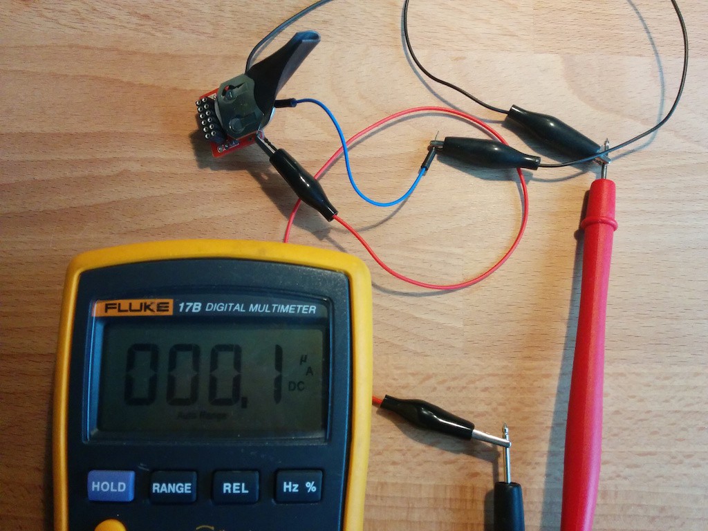
01/30/2016 at 20:31 • 0 commentsThe ATtiny85 is a really wonderful chip, it presents an array of features (timers, interrupts, watchdog, ADC, PWM...), but makes it challenging to use with a relatively low pin count, flash and SRAM. The fun doesn't have to end there though, once the code is running another challenge is to reduce the power the project is drawing. On the emitter I got it down to the lowest spec in the datasheet: 0.1uA, pretty good, but what about the receiver? It has to run all the time in order to catch the emitter messages...
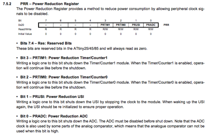
The ATtiny has a couple of ways to reduce its power usage: some peripherals like the ADC and timers can be disabled or turned off completely. The Power Reduction Register (PRR) allows to turn off the timers 1 and 0, Universal Serial Interface (USI) and the Analog to Digital Converter (ADC) - datasheet p.38.
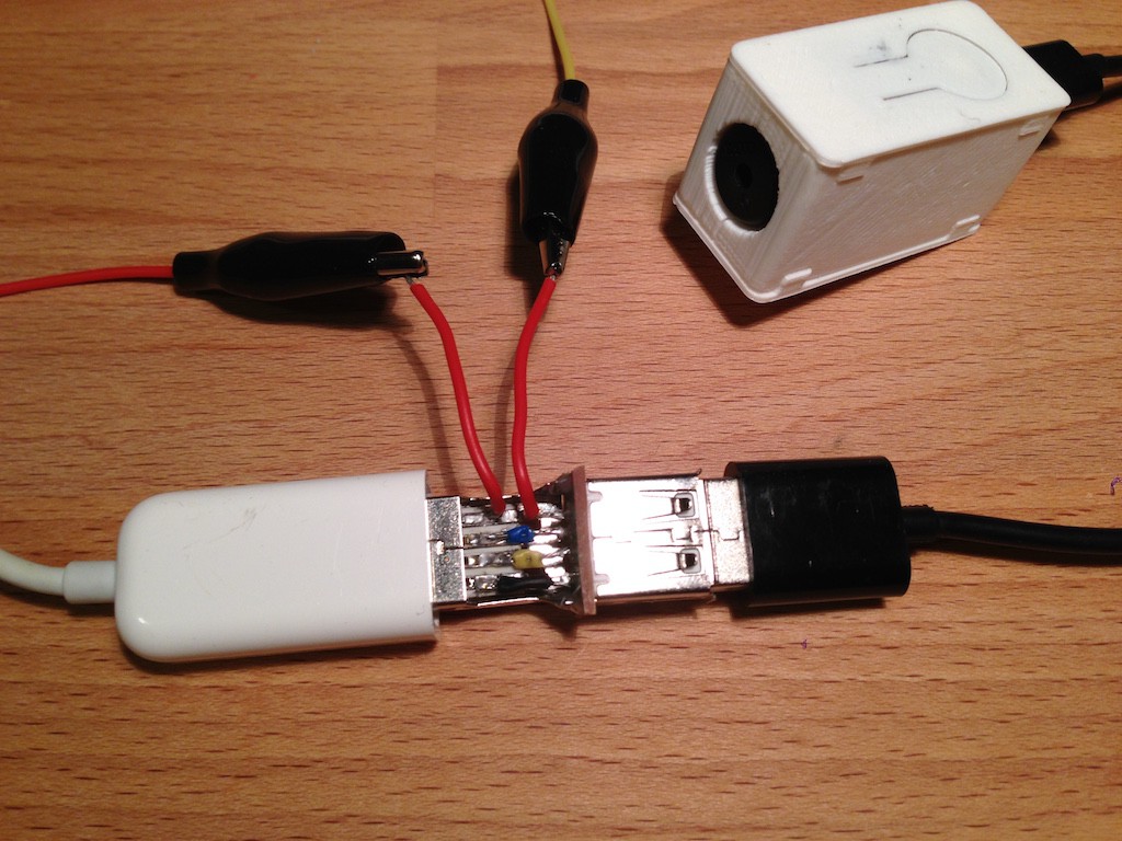
I tried to see the effects on the current when disabling the unneeded peripherals on the receiver (ADC and USI), the difference was a notable 2mA, lowest consumption achieved was 19.5mA at 5V, a full 10%! Just for kicks: this is about 850Wh per year when run constantly, at 0.2CHF/kWh it costs 0.17CHF to run the receiver for a year. Disabling the unused peripherals saves 0.017CHF per year.My current measurement setup involved some crude, self-made tools. -
Show me the code!
01/30/2016 at 09:13 • 0 commentsI tend to develop projects in parallel and some get priority over others depending on how interesting they are to me. This project was pushed back of the list for some time (I started it in the end of 2014), but I always try to publish my whole project files/sources sooner or later.
So here it is: the GitHub repository for the Snail Mail Notifier. It contains the circuits for the emitter and receiver, in perfboard, etched and PCB formats. There's also the code for both ends and some pictures. The current documentation on Hackaday.io is sufficient for now I think.
Fun fact: the compiled code on the receiver is just 2 bytes shy of the total available flash memory.
-
Programming the emitter
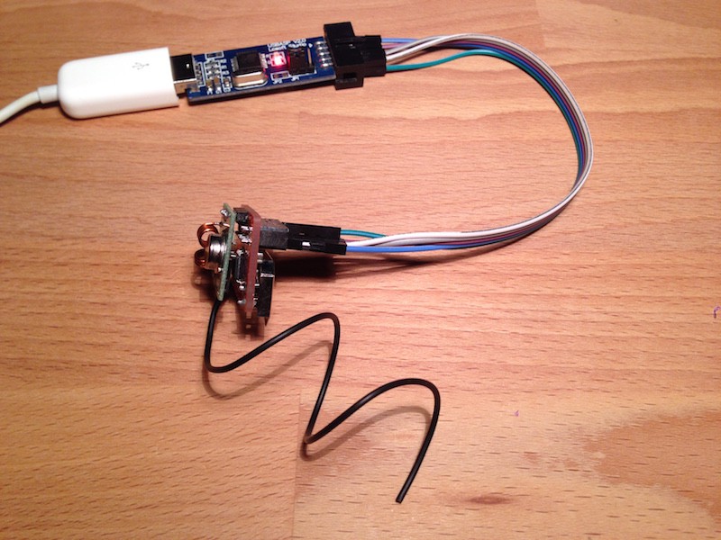
01/23/2016 at 10:32 • 0 commentsThe emitter does not need USB, actually adding USB would probably increase its power usage, so instead if using micronucleus bootloader, which adds unnecessary overhead, it will be programmed using an ISP programmer like USBasp.
To program the emitter follow the instructions on High-Low Tech to add support for the ATtiny on Arduino IDE.
The emitter needs the VirtualWire library. Download it from here (link in the middle of the page) and stick it in the ~/Arduino/libraries/ folder.
The receiver uses a special version of VirtualWire library (modified to work with micronucleus) in its own library folder, this new one will be in conflict with it (since they have the same name), to solve this issue rename the downloaded folder to VirtualWire_emitter. So instead of having ~/Arduino/libraries/VirtualWire you should have ~/Arduino/libraries/VirtualWire_emitter now. You also need to do it for the VirtualWire.cpp file, VirtualWire.h file within this folder and finally in the VirtualWire.cpp file you need to change the include from VirtualWire.h to VirtualWire_emitter.h. This way there won't be any conflicts between the two libraries.
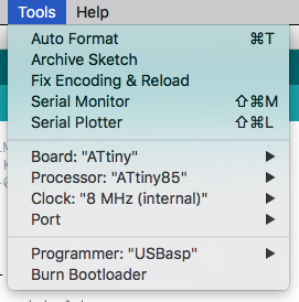
Restart Arduino so it loads all the libraries and select the configuration to program the emitter:
Select the ISP programmer you have at hand. Note that you cannot upload the program using the Upload button, you need to select Sketch->Upload Using Programmer.
-
Programming the receiver
01/20/2016 at 07:21 • 0 commentsThe receiver is a blatant copy of a Digispark with a format that suits this project, therefore it can be programmed the same way.
The latest library version has a required fix for this project, but it don't seem to be working very well with Arduino IDE, so follow the official Digispark tutorial on installing the libraries via the board manager in Arduino IDE and implement the fix yourself. I used Arduino IDE 1.6.7 at the time of this writing.
The needed fix is one line in the VirtualWire library that comes with Digispark. Find the VirtualWire.cpp file (on OSX it's located in /Users/[user]/Library/Arduino15/packages/digistump/hardware/avr/1.6.5/libraries/VirtualWire/) and on line 273 add "const" at the beginning, otherwise the compiler will bitch about it (and tell you exactly where the issue is). It should look like this:
const uint8_t prescalers[] PROGMEM = {0, 0, 3, 6, 8, 10, 12}; /* Must be outside the function */Before the microcontroller can be programmed from Arduino IDE via USB it needs to be loaded with the micronucleus firmware. I installed the 1.11 version. The Digispark library comes with the micronucleus uploading tool for 1.x firmware, it does not work on 2.x ones.
Download the Github files for micronucleus firmware and extract them wherever. Connect the ATtiny to your computer via your trusty ISP programmer (I used USBasp) and upload the firmware using the following command.
avrdude -c usbasp -b 19200 -p t85 -U flash:w:micronucleus-1.11.hex -U lfuse:w:0xe1:m -U hfuse:w:0xdd:m -U efuse:w:0xfe:mFinally it seems the Digispark libraries have some authority issues on OSX, the uploading tools have a missing executable flag, so add it manually:
chmod +x /Users/[user]/Library/Arduino15/packages/digistump/tools/micronucleus/2.0a4/launcher
chmod +x /Users/[user]/Library/Arduino15/packages/digistump/tools/micronucleus/2.0a4/micronucleus
Now you can upload files comfortably form Arduino IDE via USB. You need to unplug and replug the device after clicking the Upload button in Arduino IDE each time though.Take a moment and marvel over what has been achieved here, USB protocol if a fussy one that requires impeccable timing, now it runs on an ATtiny which, in addition, can reprogram its flash memory and execute a bunch of other things... that's some very sexy optimisation right there.
-
3D printed something something...
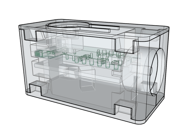
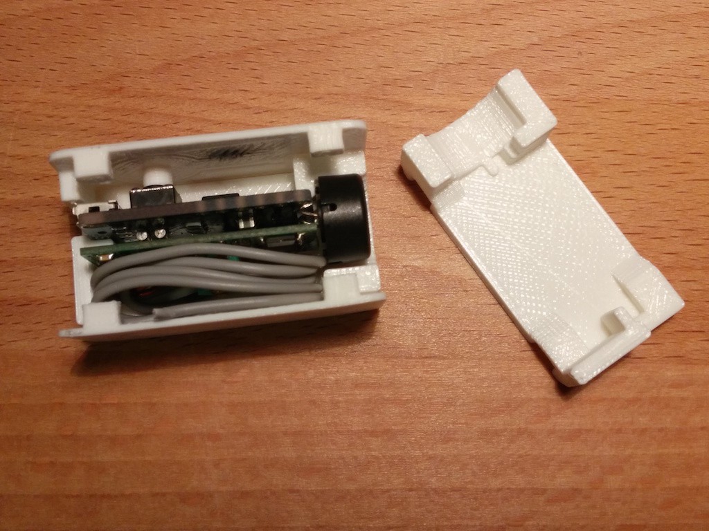
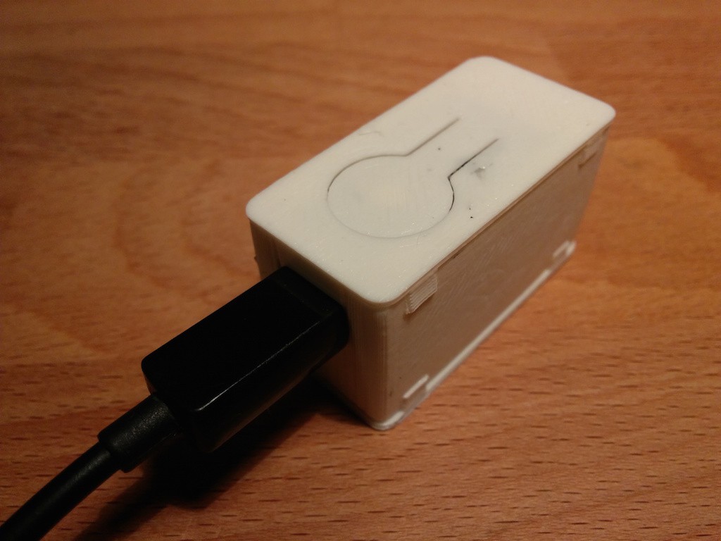
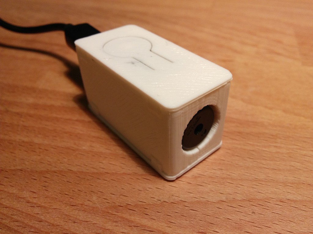
01/27/2015 at 18:49 • 0 commentsI printed an enclosure for the receiver using SketchUp, it has 4 interlocking parts and no glue is required to assemble it.
It has a flexible part on top that allows the user to click on the button which currently serves as a reset button. When the receiver gets a transmission it stops accepting messages for 1 hour, the button resets that timeout.
I didn't want the antenna to protrude from the enclosure so I tucked it inside. At first I only had about 2m transmission distance, I swapped the 1/4 length antenna (~17cm) for a 1/2 length (~34cm) which didn't improve the reception. The solution was to tune the small coil on the receiver, I guess by changing anything on the antenna will require some tuning, so I'd recommend anybody having transmission distance issues wit these modules to rip off the red lacquer and start turning the thingy until it works.
-
The life of the battery...
01/24/2015 at 14:48 • 0 commentsNow that I have the hardware the project is fun again and it's advancing much faster than I anticipated :).
I have tested the ATtiny85-20SU and ATtiny85V-10SU for power consumption in power-down more on the emitter, they're basically the same, so I can remove the technically more power efficient V-10SU-type from the parts list and use two 20SU-types.
At first I wanted to use the V-10SU-type because it can still reliably work at 1.8V, but I forgot that the transmitter also needs decent voltage to be able to emit something (it's actually rated between 3 and 12V), also the 3V coin-cell battery would be pretty much deceased at 1.8V, even with some remaining voltage when the transmission would begin the voltage would probably fall to 0, so two 20SU it is.
As written in the datasheet the ATtiny uses 0.1uA in power-down mode, that's what I measured, this is quite incredible and a 200mAh CR2032 battery would last 228 years! Now to be more realistic the transmission takes about 7mA for a fraction of a second which is not negligible, even if only about once per day and the weather conditions and battery self discharge also play a role in battery life. But my goal was 1 year of battery life and that's probably satisfied.
I have also implemented a one-minute waiting period after the message has been sent so that multiple messages, and thus excessive power, wouldn't be used when different things are inserted in the mailbox. In Switzerland, and Europe in general, the mailboxes usually have 2 compartments: one for the letters, closed with a key, with an lid that moves inside the mailbox and another one, for small packages, with a little door that opens outside. The mailman will drop the letters in the letter compartment one by one and will this trigger the system multiple times requiring this setup.
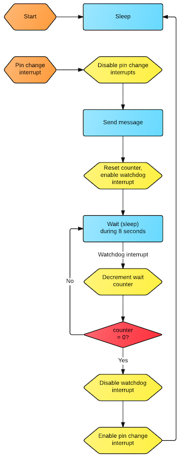
During this one-minute waiting period the MCU uses 4.3uA as it uses the watchdog that sleeps for 8 seconds, decrements a counter, and continues to sleep until 8s*8=64s have passed, then it disables the watchdog and returns to power-down mode (0.1uA).
 I drew a state machine of how the emitter works using Lucidchart:
 The reason to not use a reed or a light sensor is evident here: an active sensor needs power (>1mA), but why use an active sensor when a passive uses absolutely no power whatsoever? That's why a simple lever-switch is the best kind of "sensor" in this scenario.
 -
Steady...
01/23/2015 at 16:02 • 0 commentsI have tested the wireless communication and it works really well even with a discharged 3V coin cell on the emitter (~2.5V). I'm currently squeezing an enormous amount out of the ATtiny85 on the receiver side and that's exactly what I love about this project.
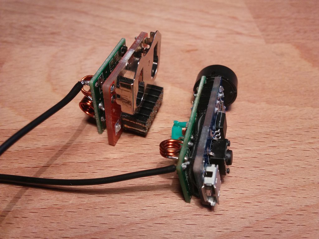
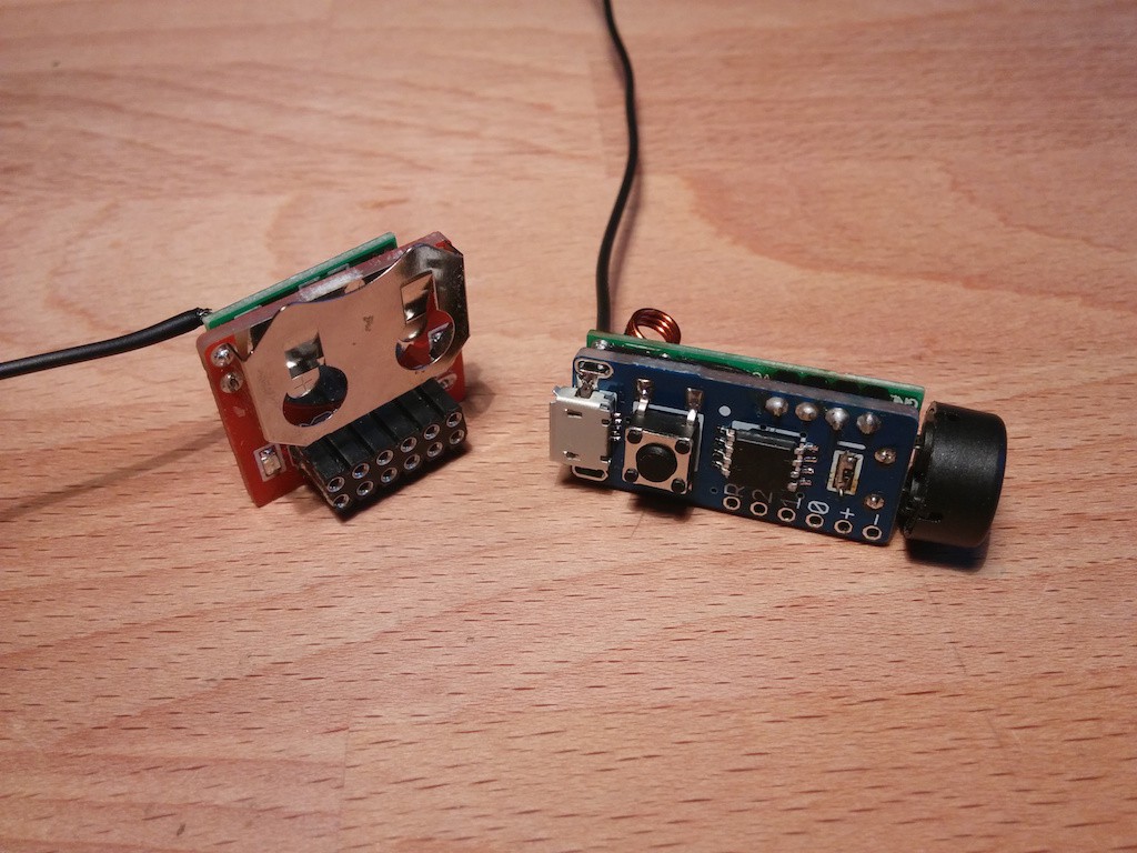
The receiver board basically copies Digispark which has mainstreamed the USB connectivity with the ATtiny. USB is horrible as the protocol timings are critical and the smallest deviation will make the computer barf and ignore the device, the amount of effort Digispark has put into making the ATtiny speak USB is massive and I'm really glad I can use it.
The MCU is a fighter: it's communicating with the computer via USB, makes a sound via the buzzer or fades the LED (depending on what's soldered), takes input from the user via the on-board button and all that while listening to the emitter and decoding the data. I'm almost using all the available flash memory right now.
On the receiver board the receiver module is way too close to the PCB and not very well fixed so there's a chance of shorts happening when one squeezes it too hard. That wasn't a chance I was willing to take so I inserted a piece of a broken bicycle inner-tube between them, this should prevent any issues for now.
I plan to 3D print a case by the end of the project so the inner-tube won't be necessary later-on.

I've been having transmission reliability issues, even with additional antennae (~17mm for 433MHz): for some reason I was only able to transmit at about 2-3m before I stripped the red lacquer from the green coil and adjusted it. Now I can reliably transmit 10-20m, through walls (with less than 3V!).
Another thing I've been busy with is how to interpret the data coming from the module to the computer. Since the easiest solution is the use the Digispark libraries and the only way to communicate with the computer, without having to make any drivers, is the declare oneself as a human interface device (HID), like a keyboard, I did just that: send keyboard commands to the computer.The receiver sends a user defined shortcut combination and from there the computer simply interprets that. On a Mac there's a thing called Automator (comes with the OS), one can make a service that displays a notification, then in the keyboard settings instruct the computer to call that service when the shortcut combination is entered, voilà: a desktop notification for snail mail. The Automator can also send e-mails ;).
I won't be using my Mac as a receiver though, I have a Raspberry Pi media center running 24/7 that will handle that, but that's one possible approach.
Next I need to check the power consumption on the emitter side, with different types of MCUs, and build the switch for detecting the mailbox lid state.
-
It's not a defect, it's a feature!
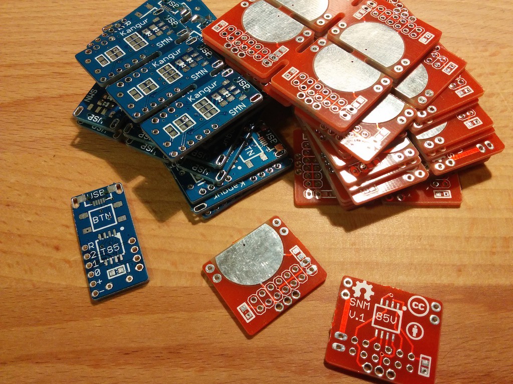
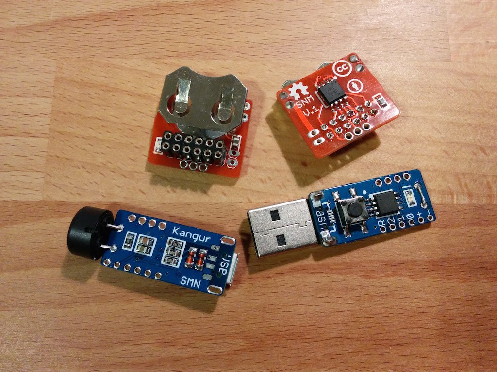
01/20/2015 at 19:04 • 0 commentsThe PCBs arrived a while ago, but I didn't have the motivation to assemble and document right away. Now that they're assembled I started screwing around and programming all sorts of useless stuff... I'm not good without a deadline.
So far I have only tested the receiver board, without the receiver module. I routed the lines the same way as Digispark so that I wouldn't have to mess around with the Digispark libraries (that was quite annoying with my prototype boards), eventually this project should be easily reproducible so that's a plus.
I routed the passive buzzer, 1K current limiting resistor and LED in series, thinking that by toggling the pin slowly I could make the LED blink and when toggled fast the buzzer would make some noise, unfortunately the buzzer is a piezoelectronic type which means it's effectively an open circuit... why didn't I test it before >_<?!? The good news is that by mounting the buzzer OR the LED and shorting the missing element they work separately. Not as pretty as I would've wanted, but eh...
The receiver board works fine and looks quite good, the emitter hasn't been tested yet, but will be whenever I feel like it. On the emitter boards I soldered an ATtiny85-20SU on one and an ATtiny85V-10SU on the other to see how they perform power-wise when in power-down mode, maybe I could cut the V-10SU from the parts list and go with the 20SU-type on both sides.
 Since there are 2 types of footprints for the USB connector (uUSB and USB-A) I soldered one of each on the boards, the same with the buzzer/LED.
I think I'll have way too many boards left over so if anyone's interested...
Now I'll be slowly, on and off, working on the software side of the project for the next couple of months.
-
New PCB order
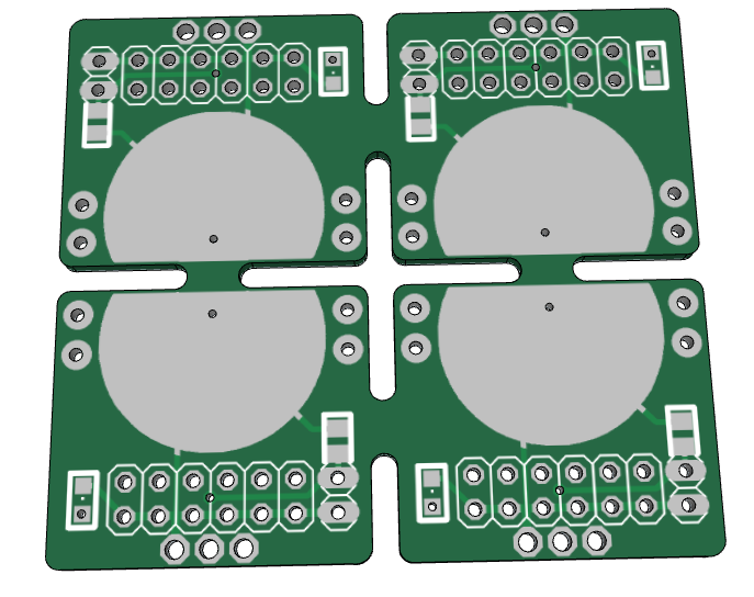
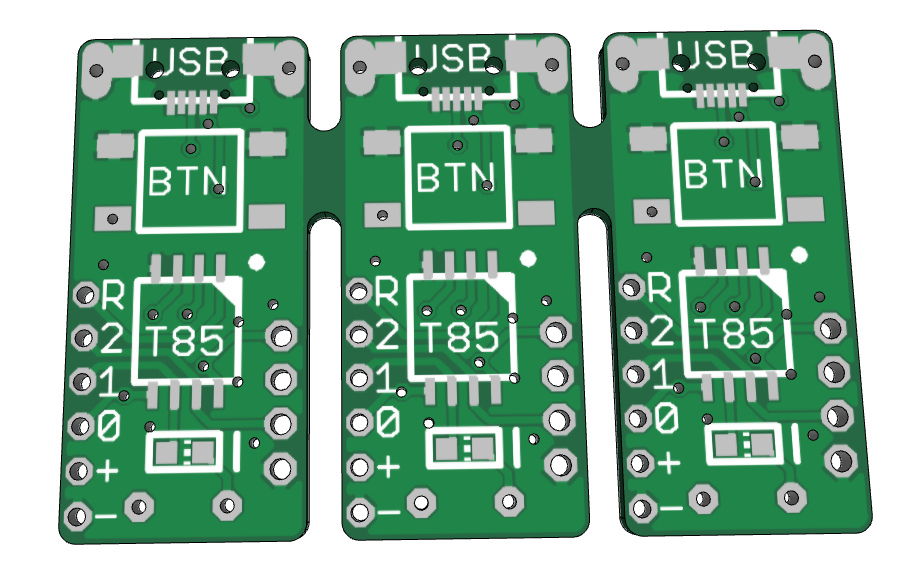
11/23/2014 at 23:24 • 0 commentsThis time I ordered 2 PCBs, I panelized the circuits since they're so small. The limit for the cheapest PCB size is 50x50mm so I crammed 3 receivers and 4 transmitters on them. From Elecrow it's still cheaper than from DirtyPCBs with shipping ($26.32 vs. $28), the actual manufacturer is probably the same anyways
-
Too cheap, denied...
11/21/2014 at 18:27 • 0 commentsAs Elecrow, and basically all other Chinese PCB manufacturers, state: only one PCB design per order. So my order was naturally refused in the end, but in rare cases it passes inspection, so I tried to be too cheap and failed.
