After all these months, the rotor is no longer just a digital CAD design.
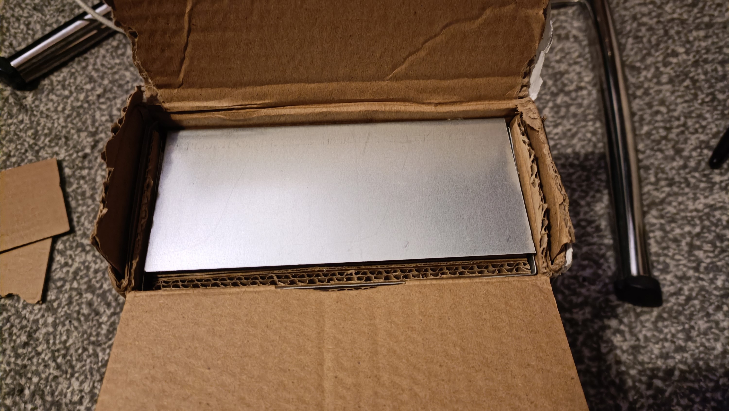
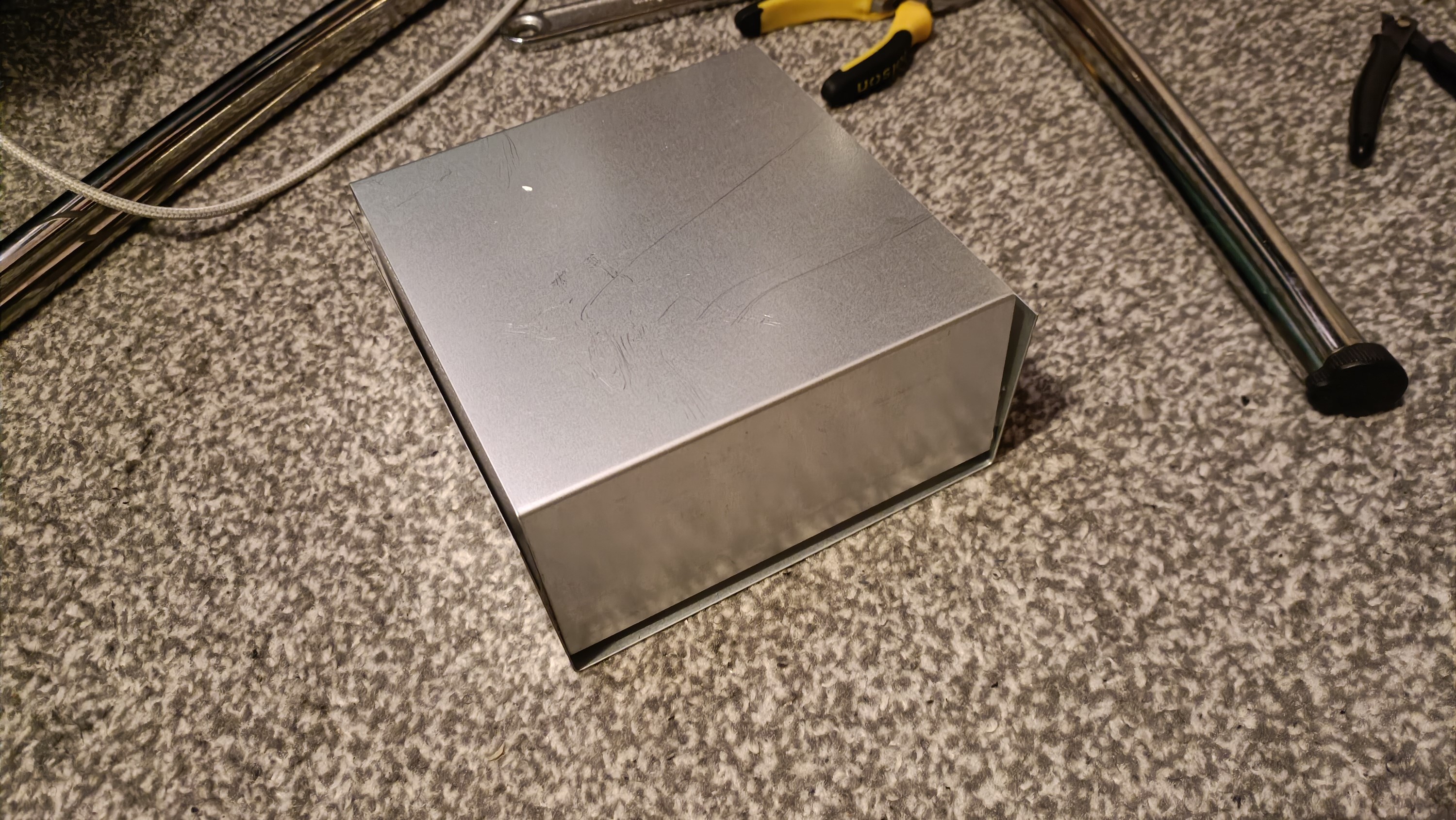
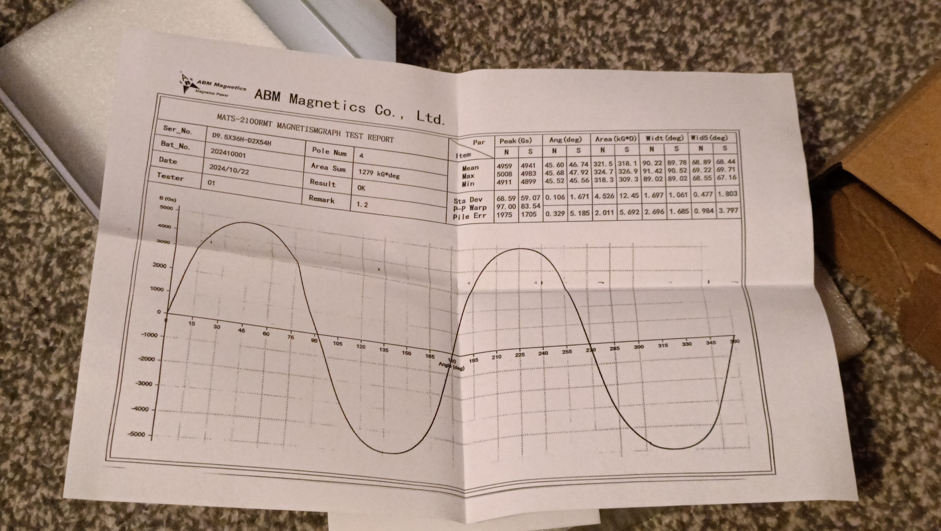
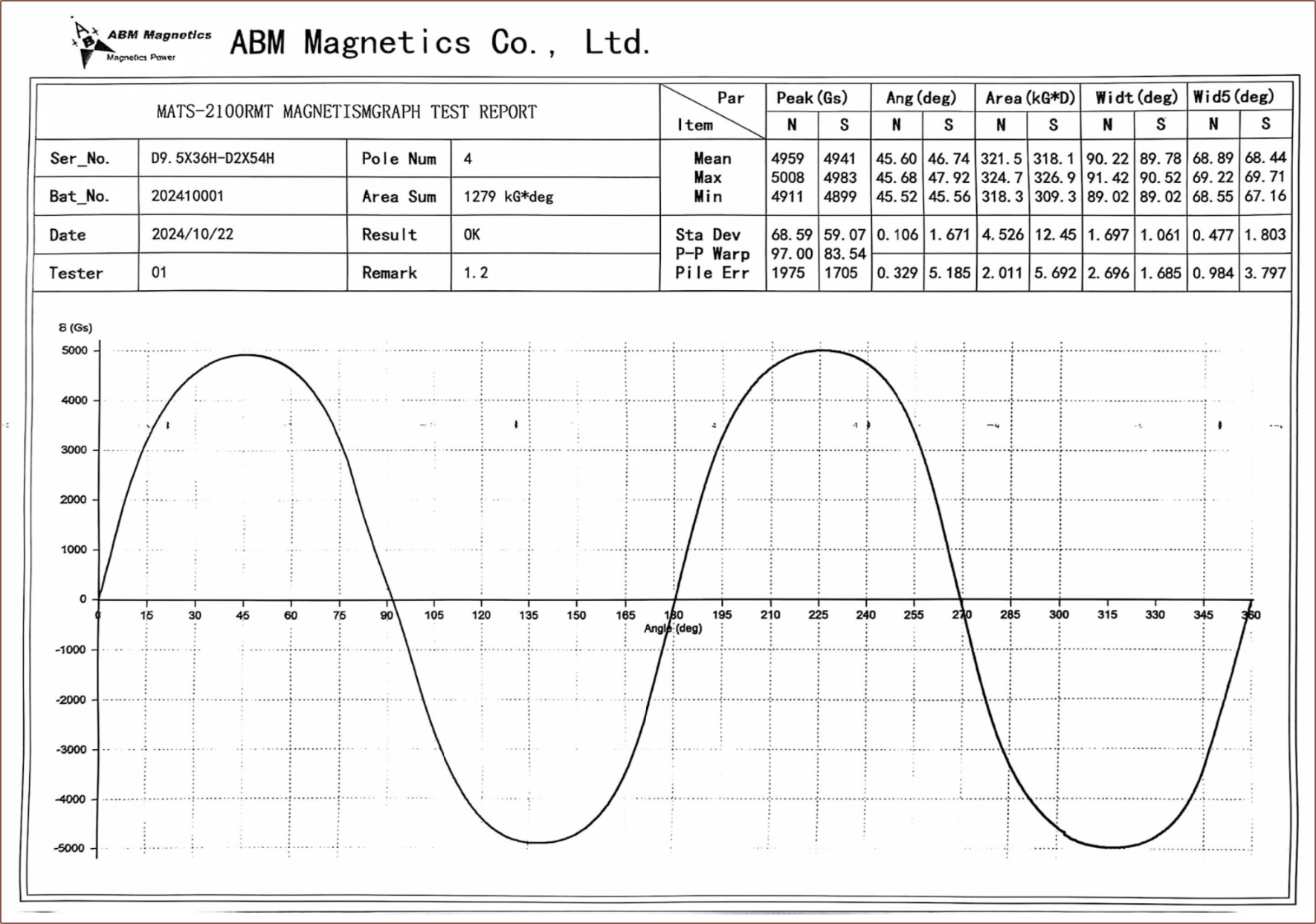
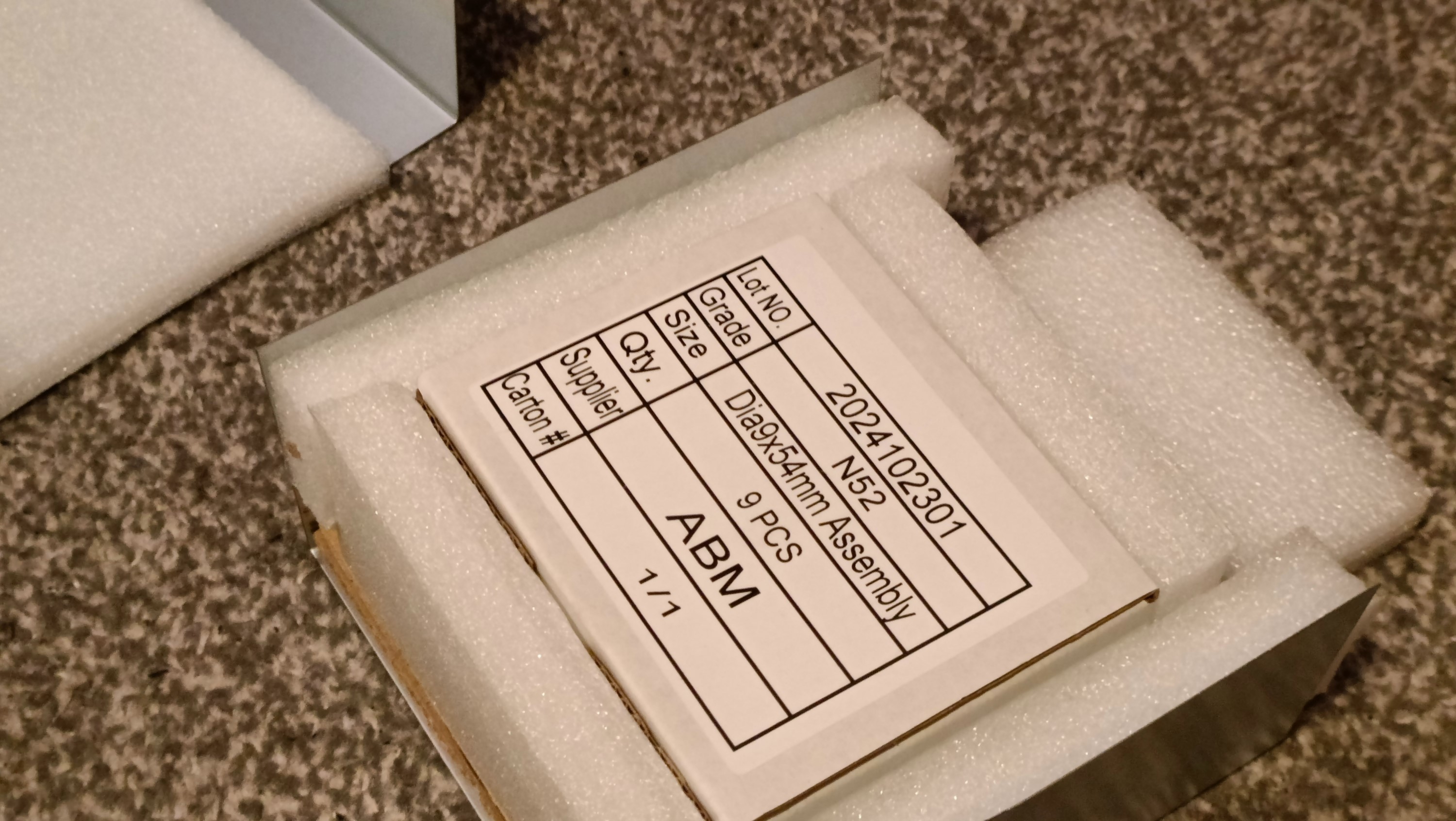
Looking at the stickers, it seems the package was delivered by 4PX and Evri, so it's unlikely that a courier is going to send a scary letter 4 weeks from now. ABM put a lot into the packaging, using metal U shape pieces inside. There were also documents relating to the rotor measurements, such as a gauss graph over 1 revolution.
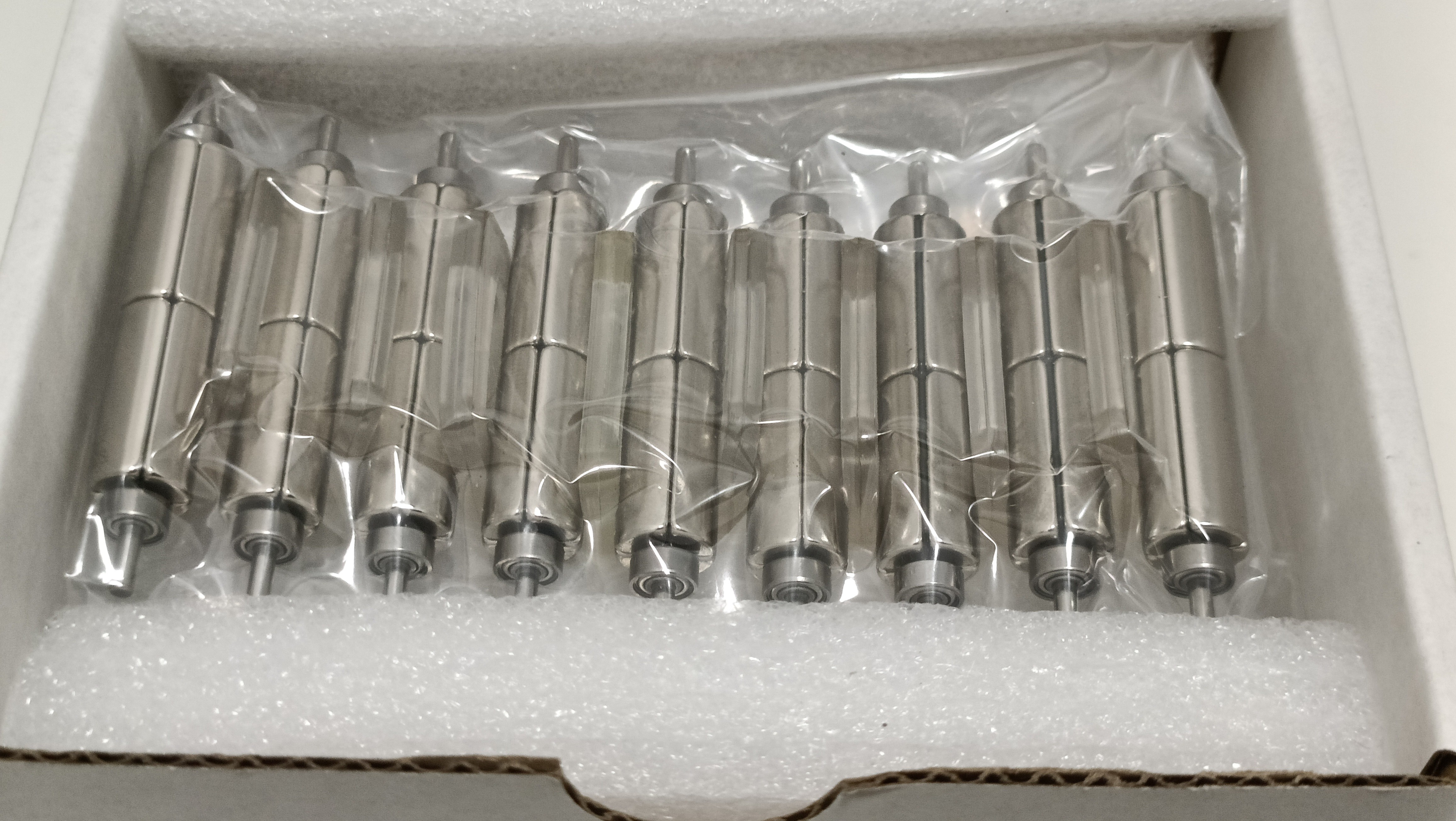
Below is a collection of images I took of the unboxing:
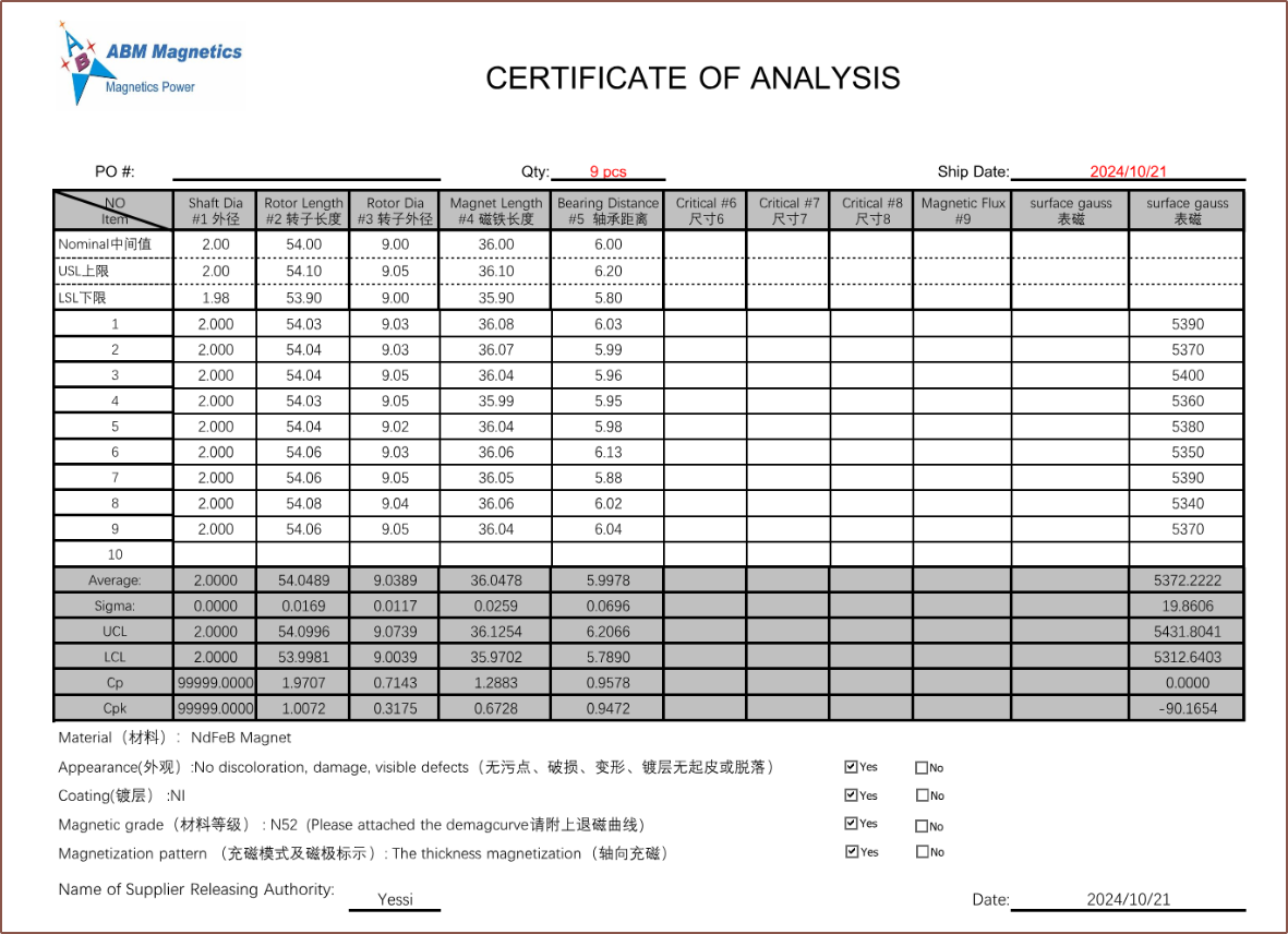
Both of these docs have a few bits of data that I don't yet know the meaning of ( e.g. kG*D, Cp, Cpk) but I can gather the geist of what these docs are talking about, so I don't think I'll need to be talking calipers to the rotors.
Me whilst looking at the contents, feeling like I'm engineering like an enterprise:
All these formal documents! All these intricate metal assemblies!
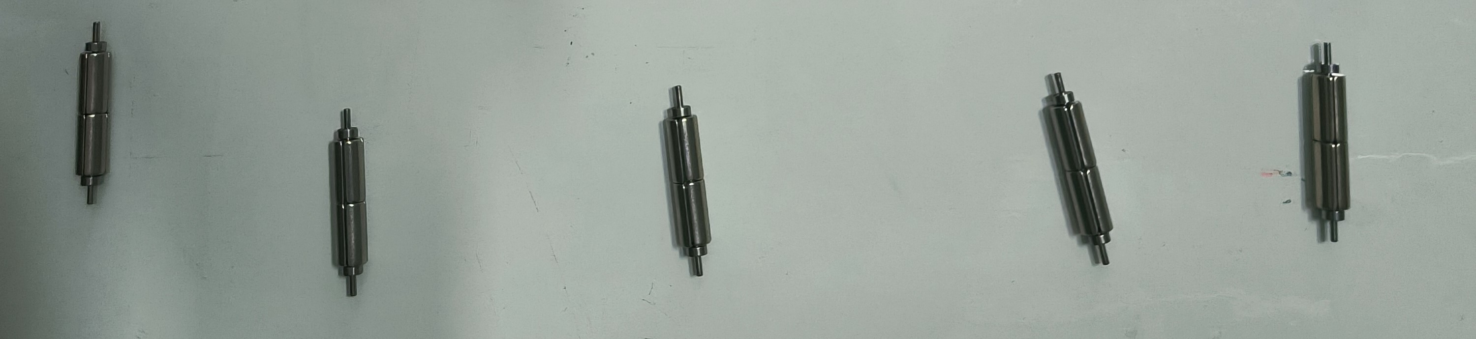
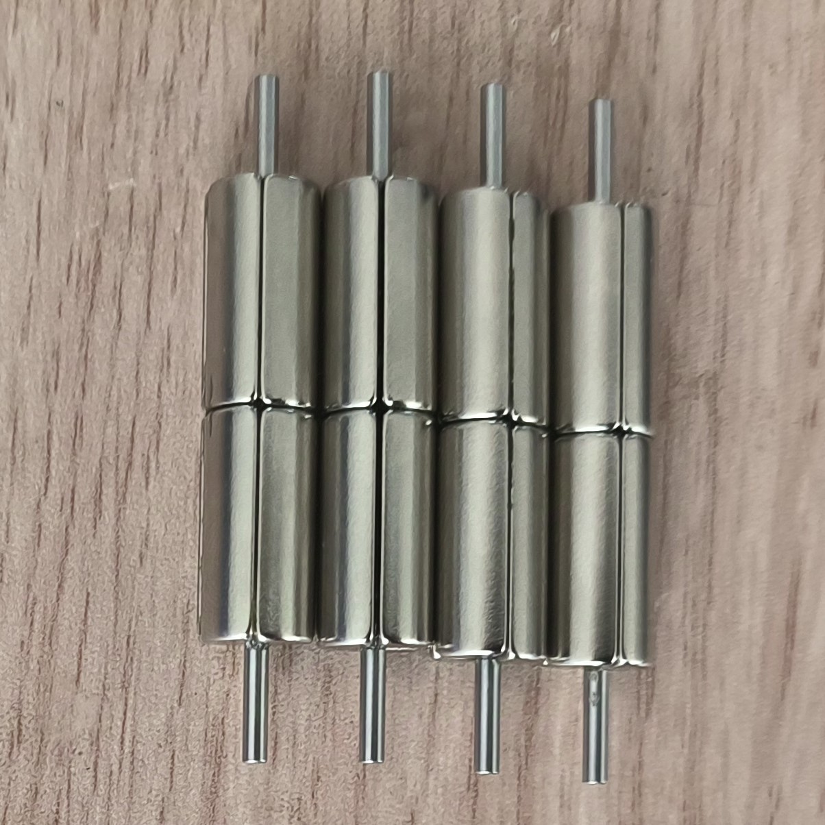
I've recently gotten some images to confirm that the rotors have been successfully manufactured:
I guess they're going to send the best 9 since that's all I ordered?
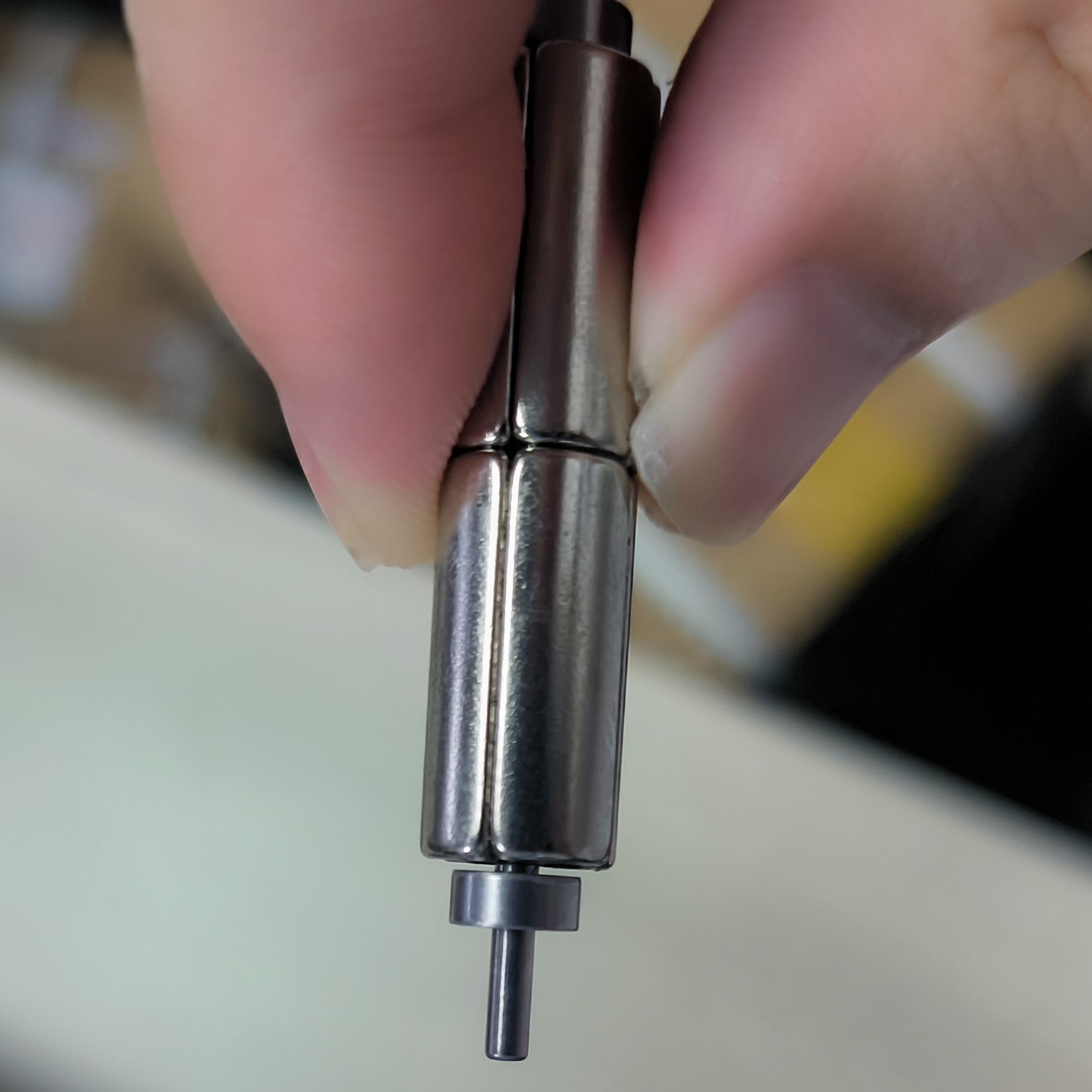
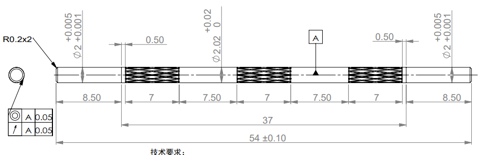
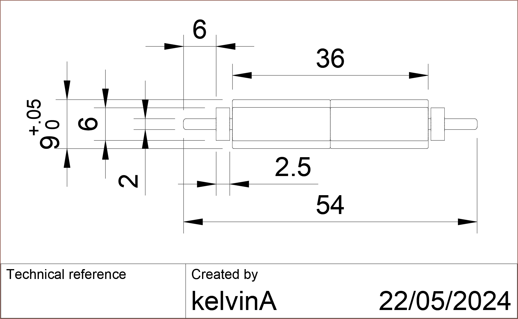
The shaft has a lot more going on than it initially appears:
The tolerances are really tight. I'm told that the ID of the bearing is 1.998mm and the shaft becomes 2.020mm OD at 0.5mm before the start of the magnets (as mentioned in the drawing I sent to them). Then, those 7mm-long knurled sections are to improve bonding between the magnets and the shaft.
Paypal auto-currency conversion
Anyway, I've been expecting some unexpected costs to occur between the rotors being made and them being in my hands, and PayPal drew first blood when I paid the remaining balance.
Unlike business to customer sites like AliExpress, on a business to business site such as Alibaba, it's typical to pay the order in 2 parts. What I didn't know (and have now disabled) is that Paypal saved Alipay as some "pre-approved" payment thing (see image below). Unlike usual, where pressing the button to pay with Paypal would show a popup where I can see and change settings, the transaction surprisingly went straight through.
I don't even know how it picks and chooses because PCBWay, for example, isn't a "pre-approved" payment.
This was an issue because I specifically changed the transaction currency to USD because my bank gave a better rate (£59.xx vs £58.50 respectively). However, £61.06 was charged seconds after pressing the button, meaning that Paypal's relatively-pricey 2.5% rate was used instead.
This is Paypal's default and you need manually change who handles the conversion for every single transaction (ie the PayPal popup) and pre-approved company (see image below). I can only assume Paypal doesn't give a global option to never use their converter because that eliminates an opportunity for a % bonus facilitating a transaction.
I'm going to mention pitfalls like these since, as explained, customers usually don't buy on Alibaba, thus online articles are usually written from a dropshipper (or other business) perspective and not some maker that needs a few pcs of a bespoke/customised part.
I must've been intoxicated with hopium if I thought I could get away with not having a stiffening tube over everything. The toroid, coils, and overmould are all flexible components around the magnet, yet finger force is applied directly ontop of the motor.
Conveniently, AliExpress has just the tube I need:
I've modelled in a 49.5mm tube so that I've got some cutting tolerance:I'd also like to avoid needing a semi-circle cutout for the silicone PCB assembly, but I don't have confidence I'd be able to get away with it. Oh, but I wouldn't be able to do that anyway or else I'd block the BT signal entirely.
Anyway, the current strategy is friction fit, potentially heating up the tube to expand it slightly before assembly.
I'm really not a fan on how tight all the tolerances for this motor are becoming.
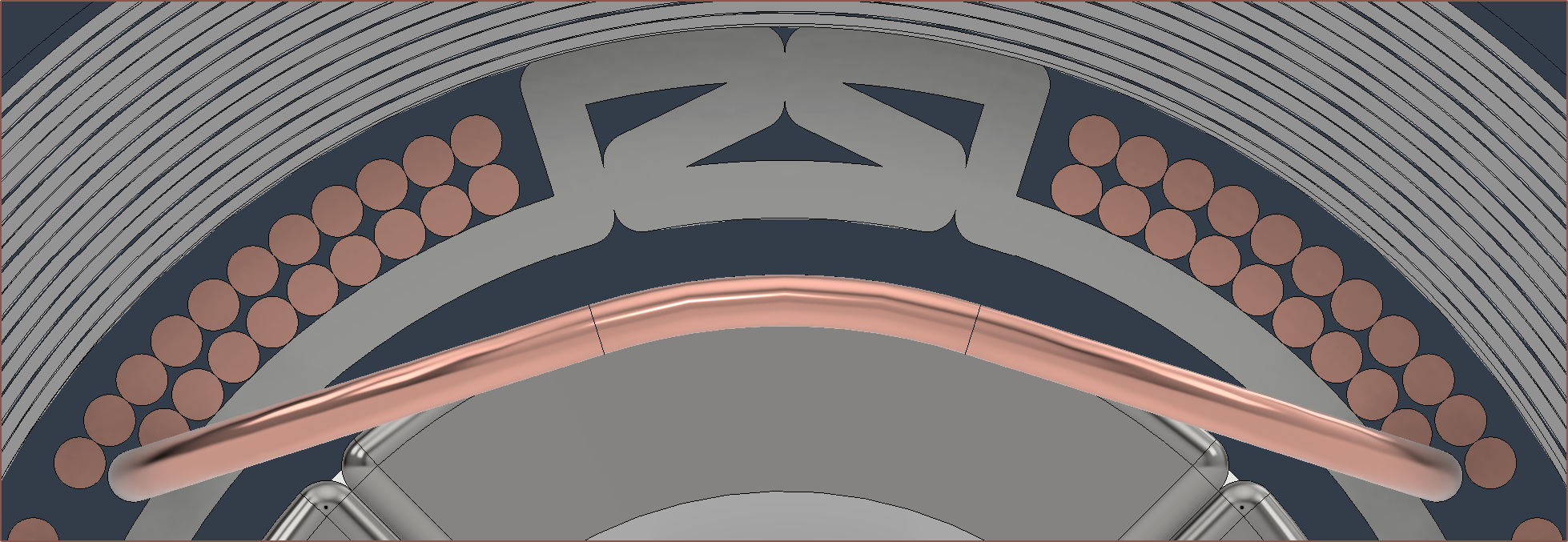
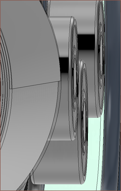
The rotor's looking pretty cool.So I've gotten some images and updates of the rotor being manufactured at ABM Magnetics. As I somewhat worried, but dismissed / suppressed the thought at the design stage, the bearings are being attracted to the strong magnets, as can be seen in the image above.
They've made a few and the quality seems mostly consistent. They certainly look good enough for a "we have a brushless motor at home" attempt.
As you may understand from the Excel calculations and Fusion CAD, there's unfortunately not a lot of wriggle room to just move the bearings and give them more space from the magnetic force.
They proposed that the were going to remake the shaft (on their dime 😀) and I said that was fine, but asked if they had tried having a thin washer between them, like the 2515 waterproof motor I saw on AliExpress.
A few days go by and the engineers tried but unfortunately wasn't going to work so we're going with the first proposal:
Our engineers looked for gaskets made of many materials, such as brass, ceramic, and stainless steel, but none of them were found.
Because the thickness is only 0.5mm, our friends can't make it.
Therefore we plan to produce the shaft and magnet again for assembly. But the delivery date may be in October.
We updated the production drawing of the shaft again and planned to increase the tolerance of the bearing position, so that the distance between the bearing and the magnet can be 0.5mm.
Because now the magnet will attract the bearing, making the bearing in close contact with the magnet. According to our engineers' experience, if we send the product to you now, it will not work.
Technically, fully ceramic bearings could also be an option, but they're £2 per bearing last time I checked.
I'm just so glad that I unintentionally found a manufacturer that could fabricate the rotor in its entirety instead of having to do the engineering thousands of miles away from the factories and have to pay for prototype and postage every time I need a respin (like the #Coaxial8or [gd0144] heatblock).
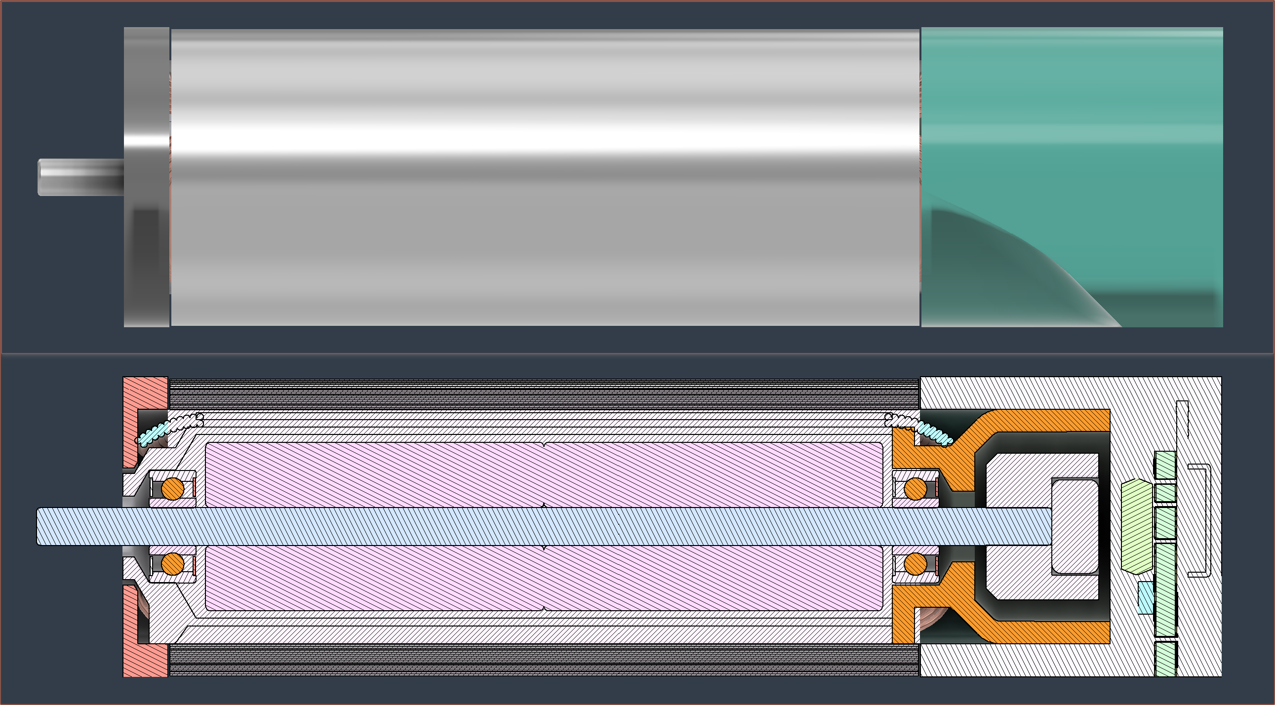
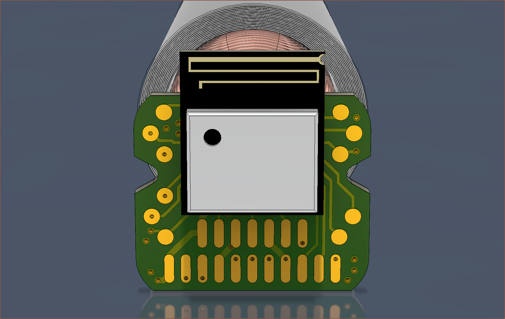
I've finished modelling the front cap (chalk red), the front of the overmould, the back bell (orange) and the silicone moulding that holds and protects the PCB. Somewhat surprisingly, mounting the PCB is easier because of water ingress protection.
I searched for a silicone mould kit and the first result had a nice colour so I used it in the model:
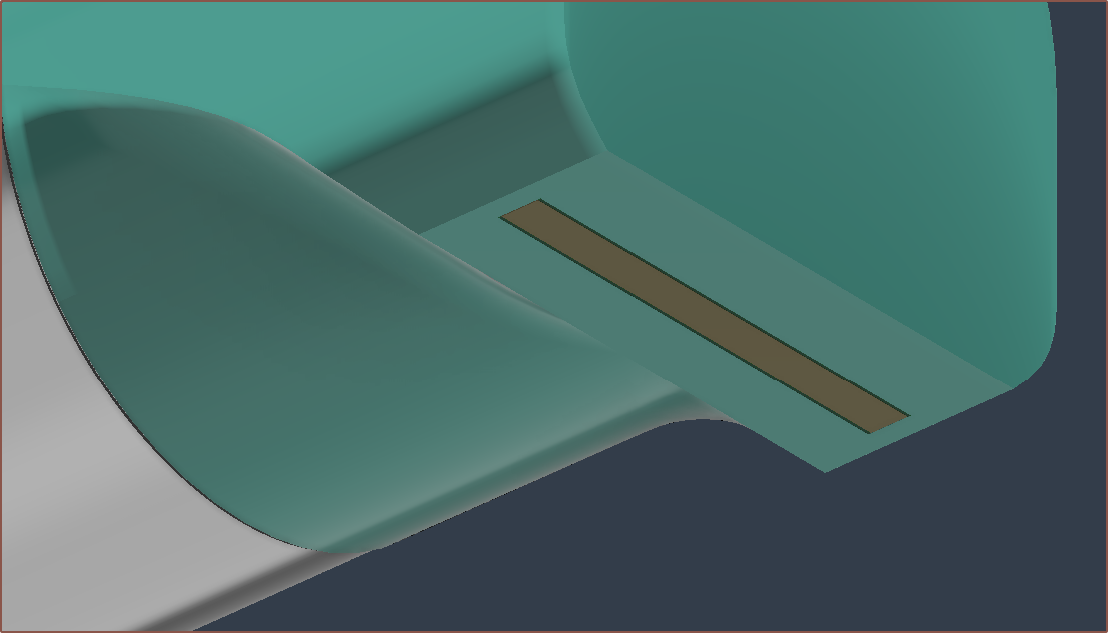
There is a small gap on each side of the bell to allow the thin wires to get to the silicone mould:
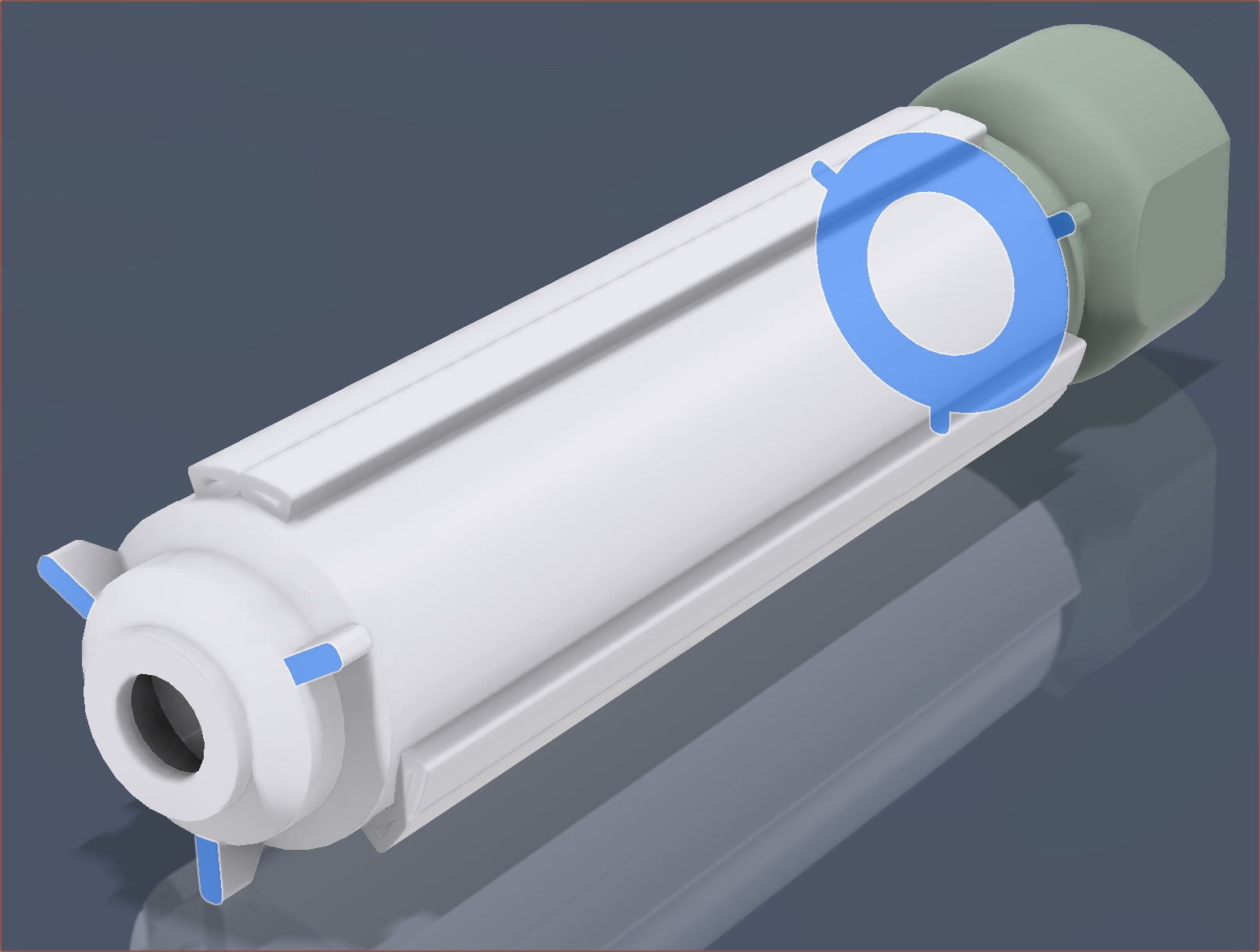
The bell and overmould have 3 spokes that help align to the toroid and front cap respectively:
I also confirmed that FR-4 does not absorb water, so I should be fine in the bottom of the PCB being exposed:
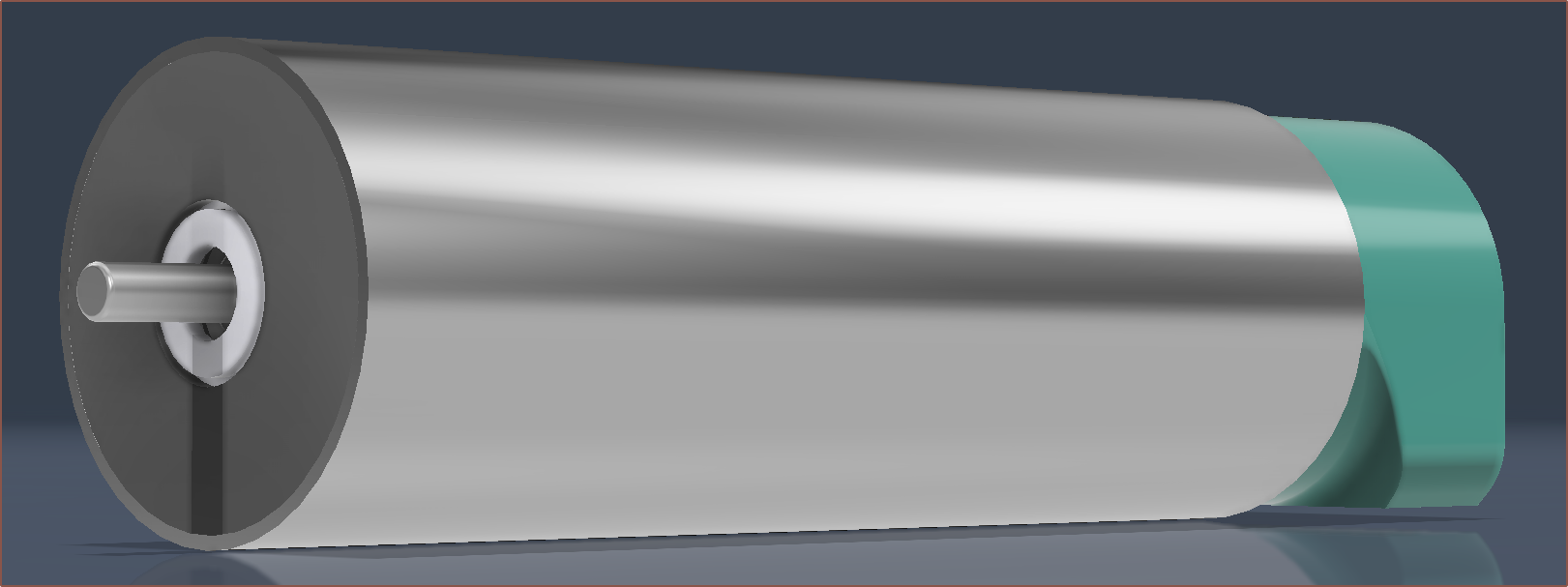
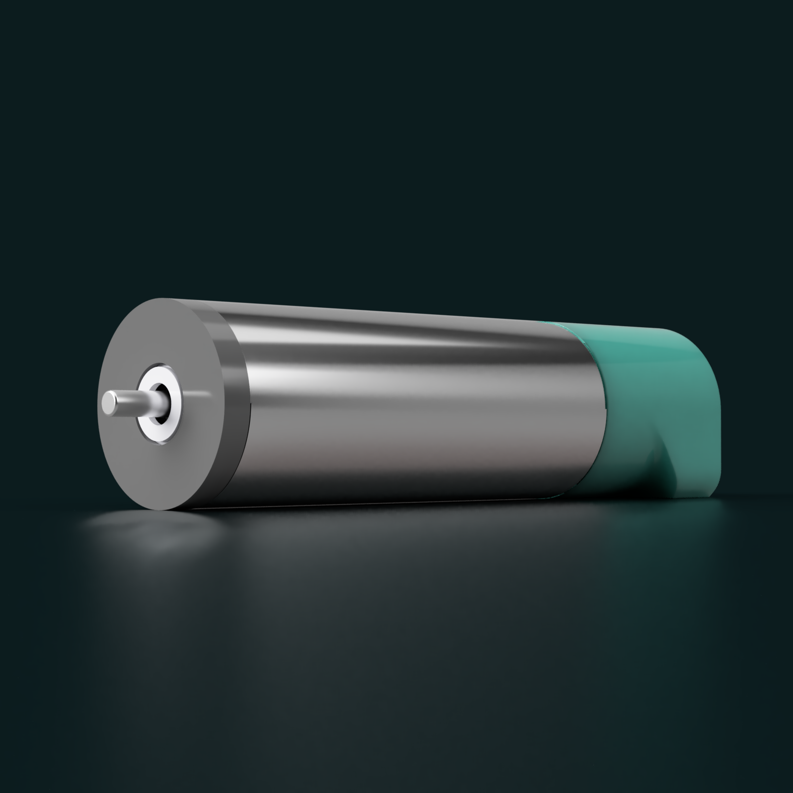
I like that the final result looks like it's just a standard servo inside a manufacturer's product catalog:
The entire length is 63mm, with the exposed shaft being 4.6mm.
Next steps would be to create the buildables for the servo.
.3MF files that can be used with vase mode
Silicone mould jig, perhaps adding draft angles
JLC assembly files
etc
In other news, I received a progress update from ABM Magnetics:
We have completed the production of rotor samples.
However, the tolerance of the shaft was increased during production, resulting in the outer diameter of the product reaching about 9.20mm after the magnet was assembled, which exceeded the tolerance of the drawing.
Our plan is to re-produce the shaft for production, which will be around August 25th.
Essentially, the range of diameters was between 9.00 and 9.20mm but the tolerance specified in my drawing was 9.00 - 9.05mm. The reason for the tight tolerances is because
changes in diameter affect the torque constant, and
the rotor needs to be able to spin freely in the overmould.
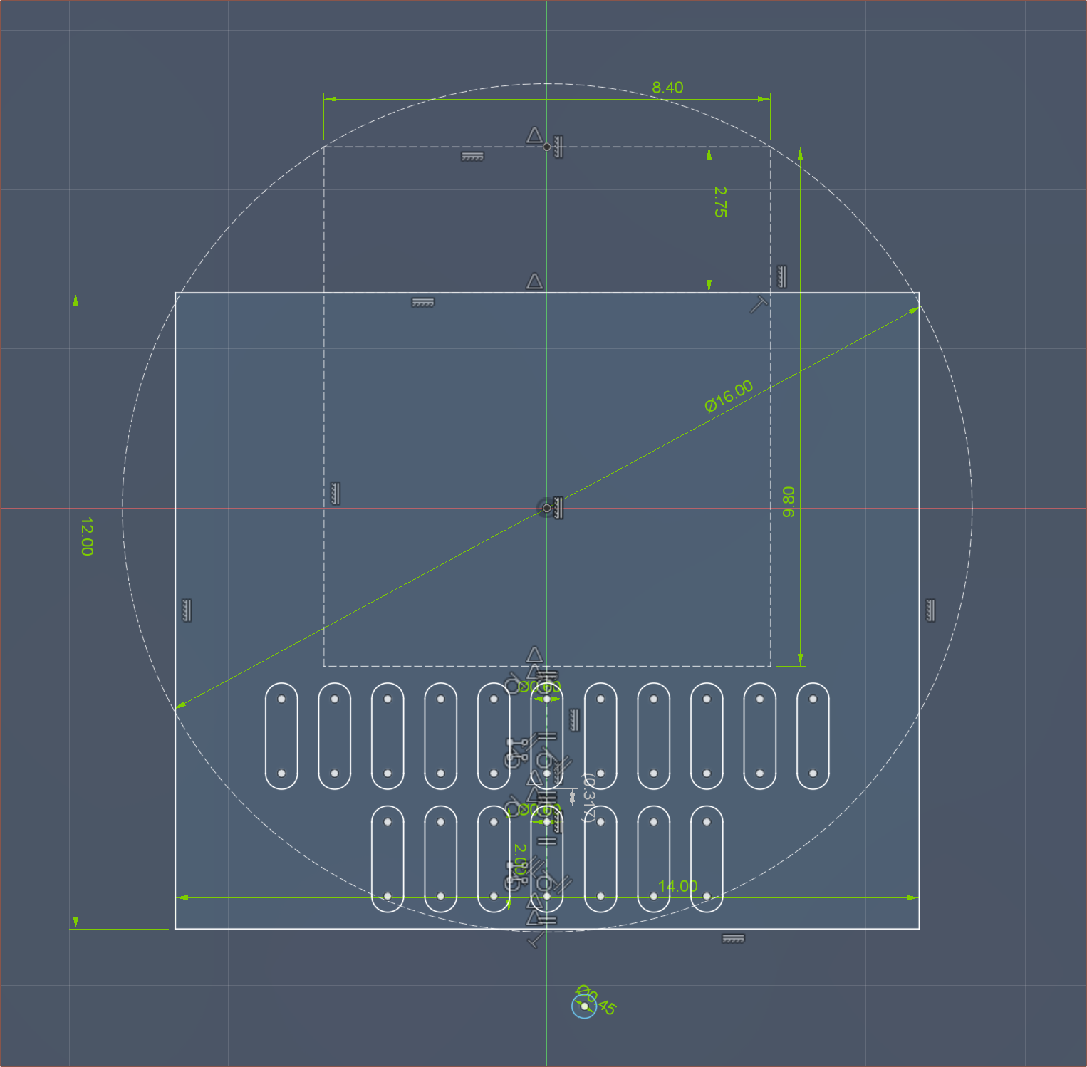
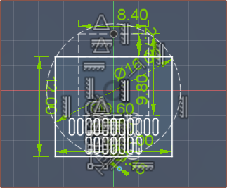
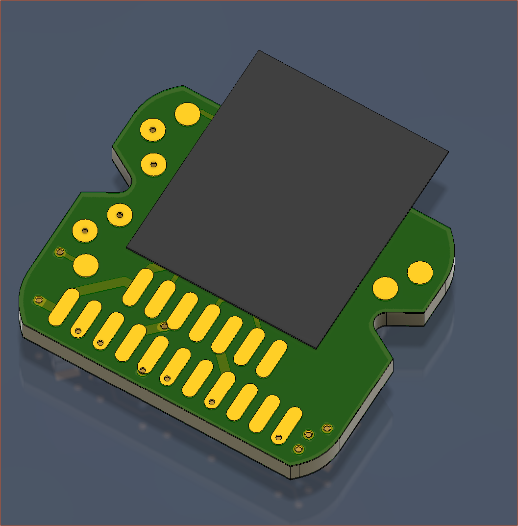
I've been working on the brushless motor PCB for the past 4 days. I'm starting to write this log when its not completely finished (I've still got the power nets to connect and the UWV pads to place), but it's to a point where I can say that a 14 x 15mm controller PCB is probably possible:
Planning the PCB size and placement
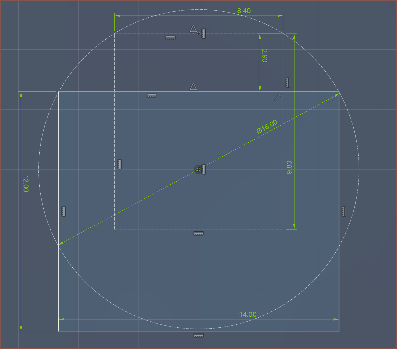
My expectation since the start of June was that I was going to have the 11 pin connector on the left and the 7 pin on the right, with test pads in the lower right. The 11 pin FCC should be 12mm, so that's what I set the height as. Additionally, I was thinking that the microphone was just going to complicate matters with waterproofing so I decided against it.
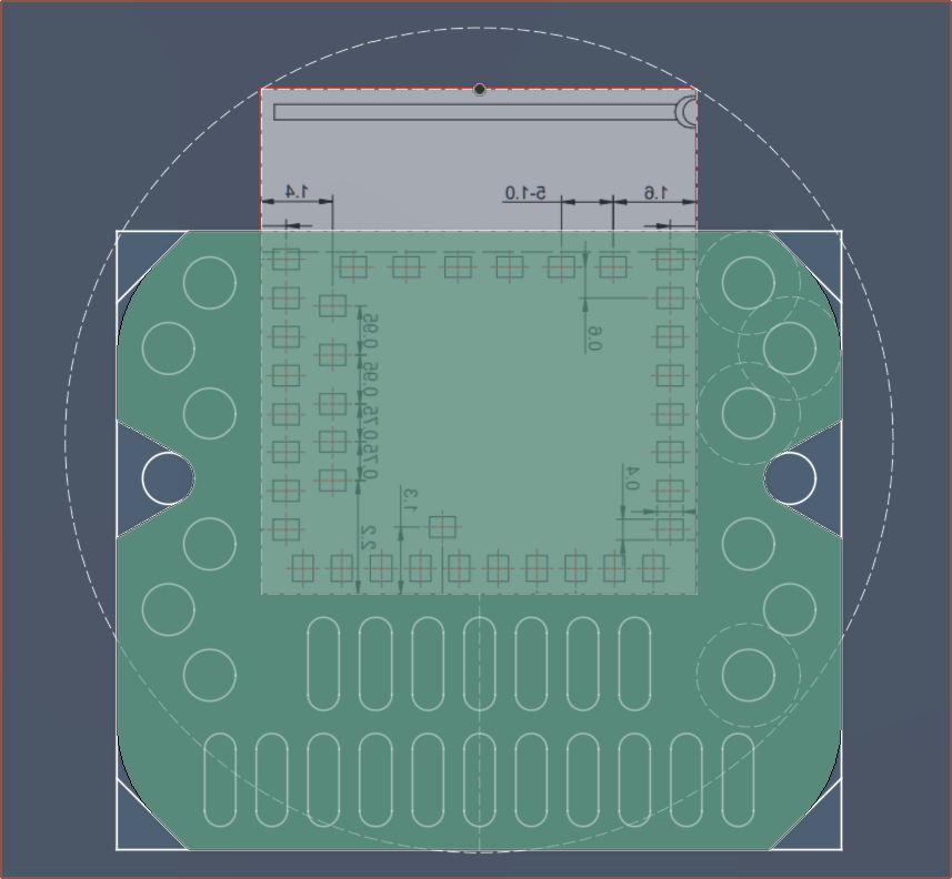
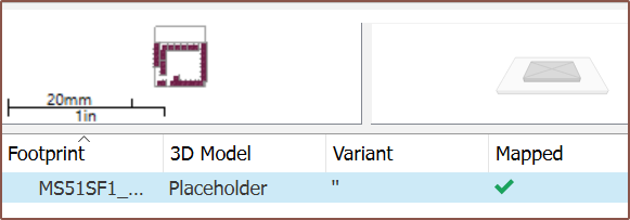
However, when I drew the dimensions of the MS51SF1, I saw 2 things:
The edges of the PCBs are on the 16mm curve of the motor, conveniently enough
There is a lot more space between the bottom of the module and the bottom of the board, potentially meaning that I could have both FFCs (flexible flat cables) coming out from the bottom (similar to the placement of wires on other BLDC motors).
That 0.45mm circle is the size of a via, for a point of reference. The pads are 0.6 x 2mm.
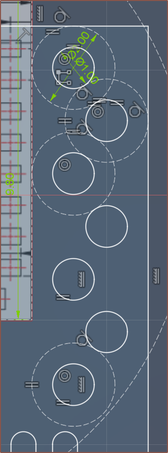
The 2nd point was even more important as the motor and gearbox bearings go edge-to-edge, meaning that the FFCs would stick out.
I zoomed out till the PCB was 1 : 1 scale and decided to reduce the height of the pads from 2mm to 1.8mm.
Then I had a think about how these cables were actually going to route out, and if the 7P was on the bottom, it would only be able to terminate on the other side of the motor. If I put it on the top, I could terminate on either side. It also had other benefits, like the FSR pin being neighbours to an analog input pin, or being able to fit a testpad array:
The vertical spacing between each pad is 1.27mm (as breadboards / through-hole pins are 2.54mm standard). I looked up the standard testpad size and one article went with 1mm ( 40 mills ). Conveniently, a 14mm wide board and 1mm spacing between pads means that the pads perfectly fit in the space.
There also needs to be a mechanical way of keeping the PCB in place, so I converted the 4th-pad location into a 60 degree V cutout:
I did tweak the chamfer so that the bottom edge was 12mm. In this image, it's a bit less than 11.5mm IIRC.
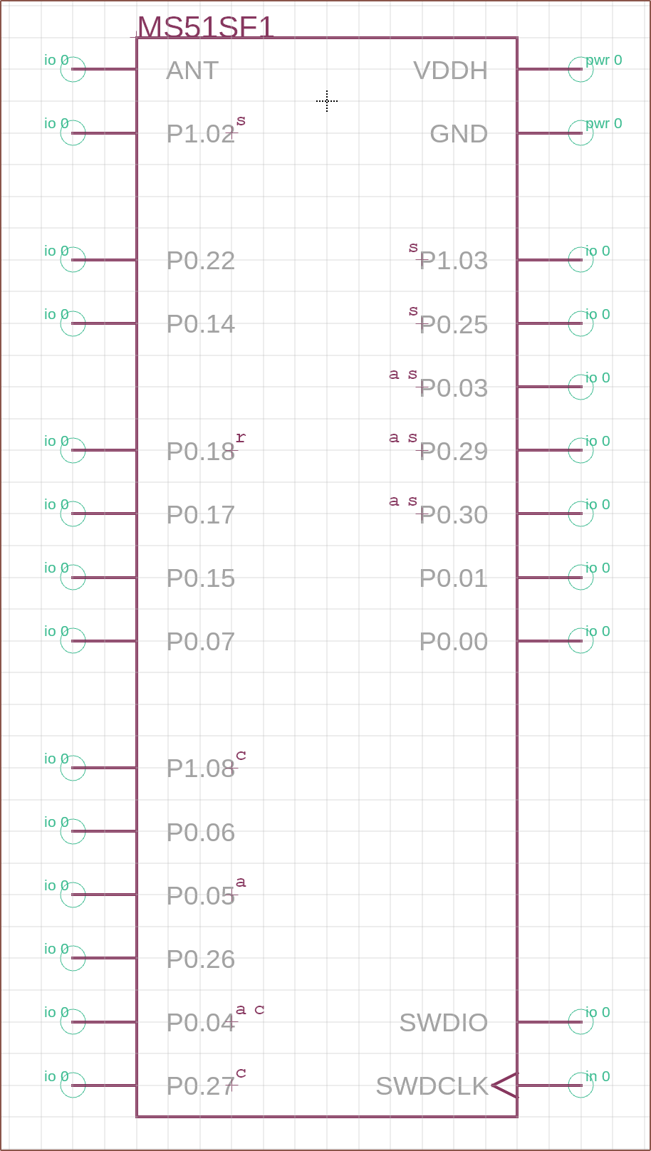
Creating the MS51SF1 schematic component
So I drew all the pins and labelled them, but then scrolled down in the nRF52833 and found out that there are 3 different packages for it and they each have different pins that are slow or are recommended for the SPI clock. I looked in the SF1 schematic and deduced that they were using the WLCSP variant, which has a lot more "low frequency I/O" pins than the aQFN I was initially looking at.
A = Analog, S = Slow, C = SPI Clock, R = (configurable as) Reset.
I'm hoping I don't actually need that reset pin. I don't think I do:
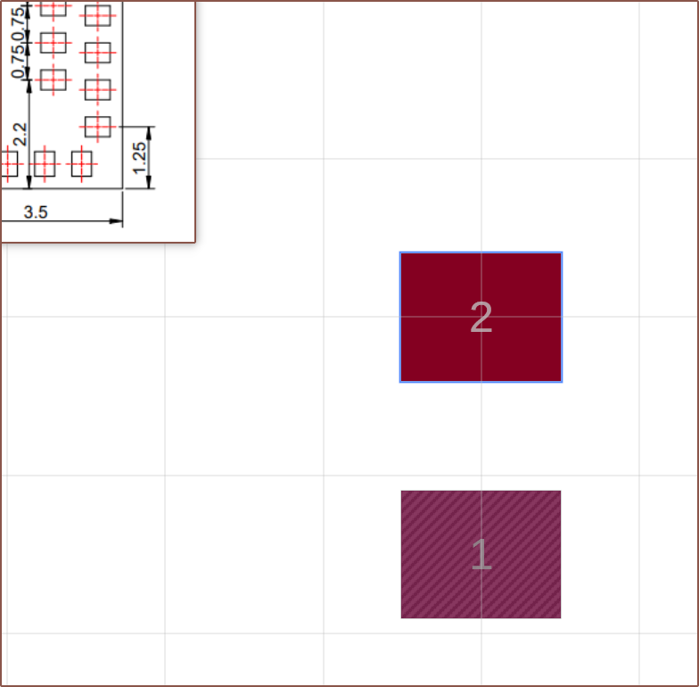
Then I started the tedious process of placing pads. It didn't take long to see how KiCAD did things, but it doesn't look like grass is greener on that side. It's just a lot of addition and data entry to get the pads in the right places, and the reason why I decided to keep everything in the positive-quadrant instead of trying to make a footprint centered around the origin.
I turned on mirror mode before doing anything, because the image shown is the dimensions on the actual module, not the footprint.
After making the footprint with the correct pad numbers, I duplicated it and deleted the pins I knew I wasn't going to use (USB and VDD):
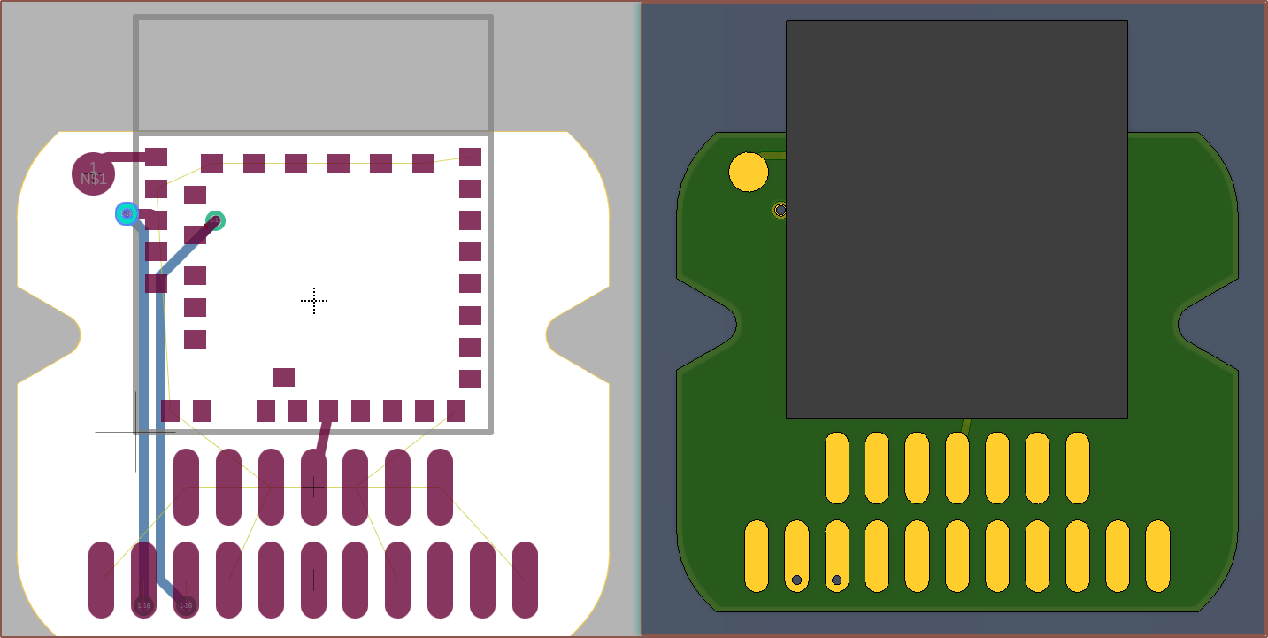
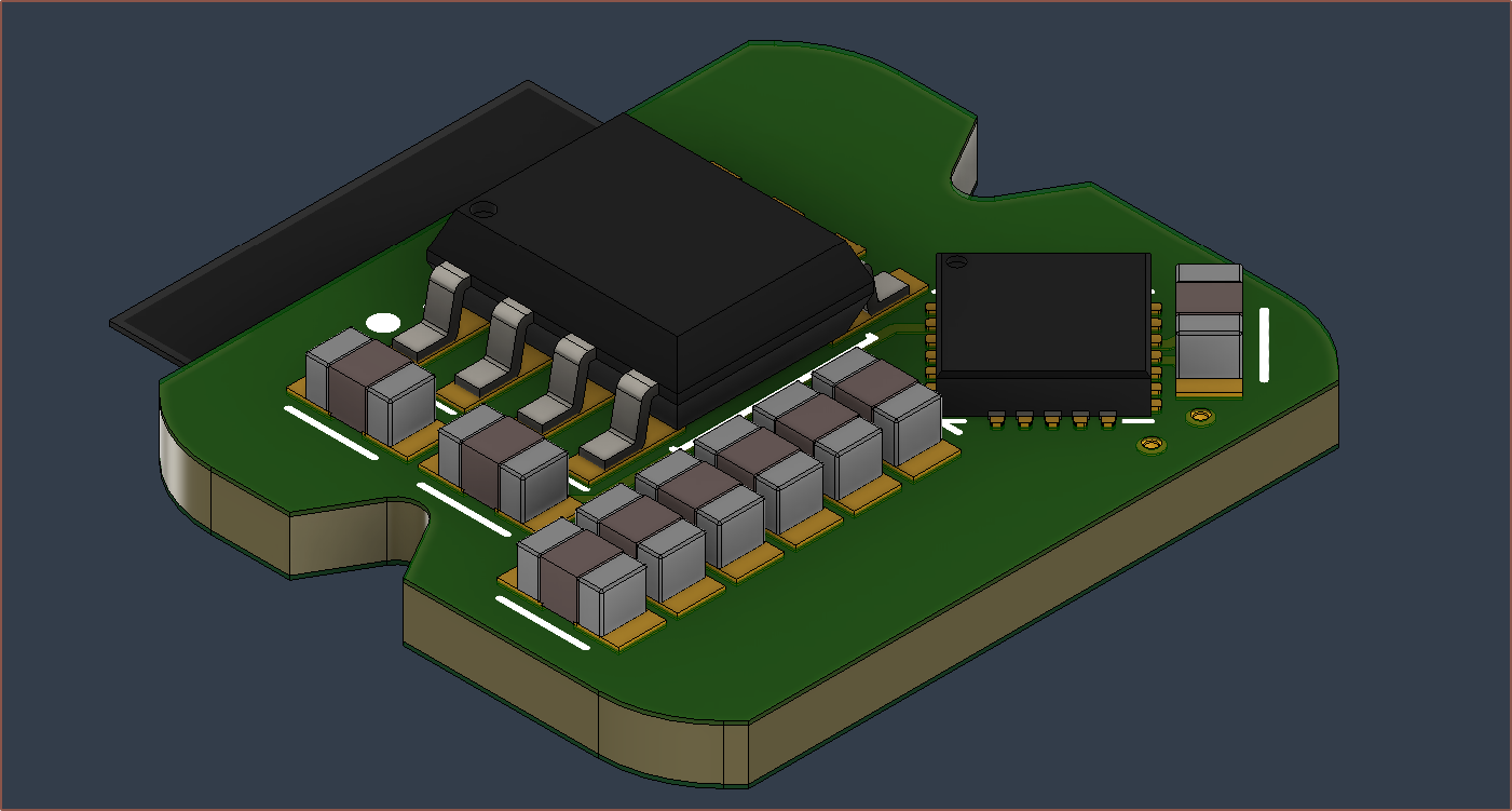
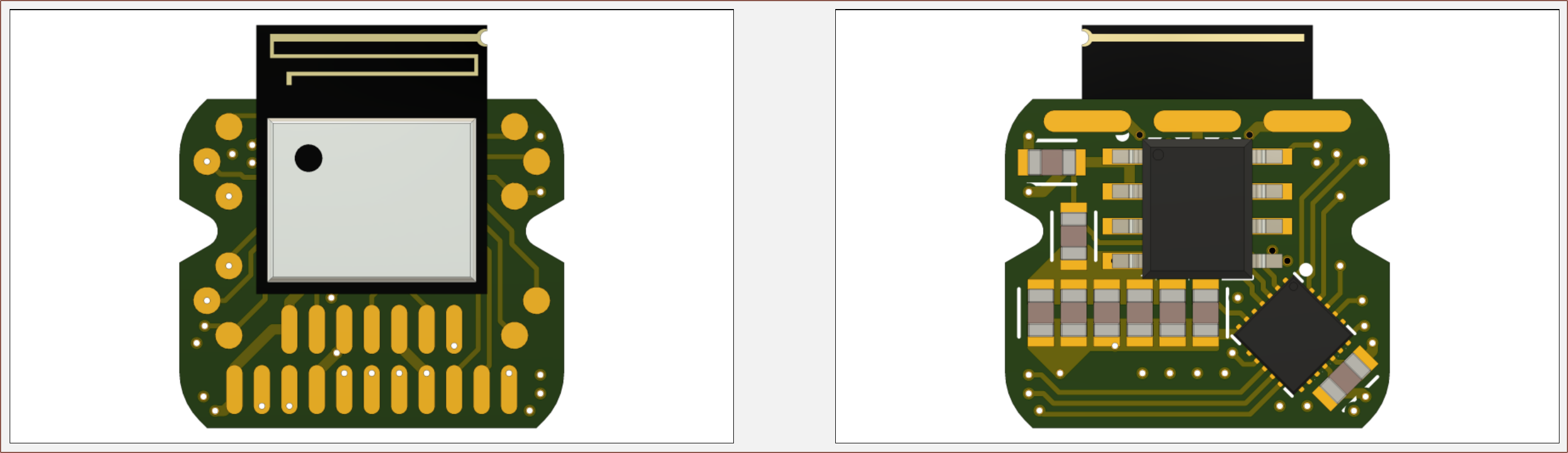
Then I placed some starter gear on the board to confirm everything actually works like how it was planned:
This time, I decided to keep the BT module on the "Top" layer.
The DRV8311P (BLDC controller) and MT6701 (magnet sensor)
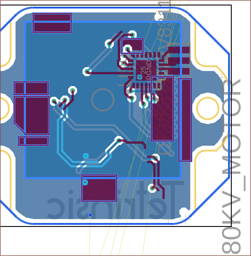
For some reason, I can't just copy part of the old schematic and place it in the new one, so I had to "Insert Electronic Design" and then delete the other parts of the schematic. This also imports the PCB apparently:
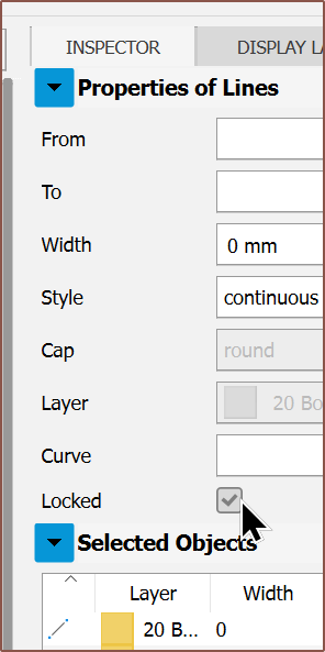
I had to first unlock the lines before I could delete them:
Additionally, I still felt like the 8SOP version of the MT6701 would be better than the smaller 16-QFN because the pins would be more spaced out.
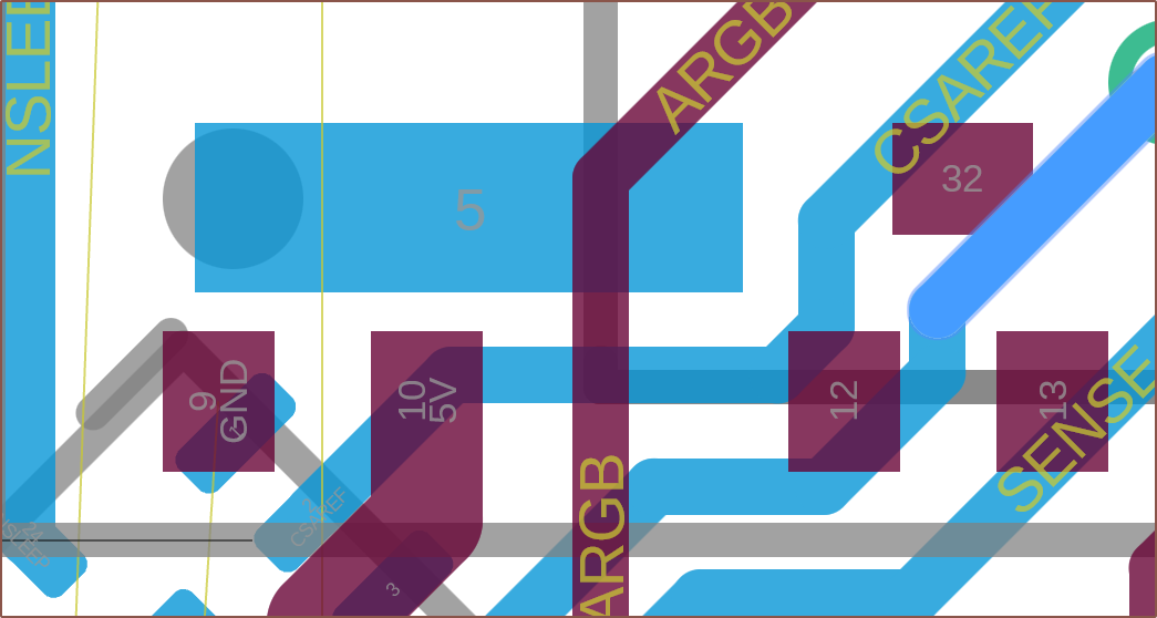
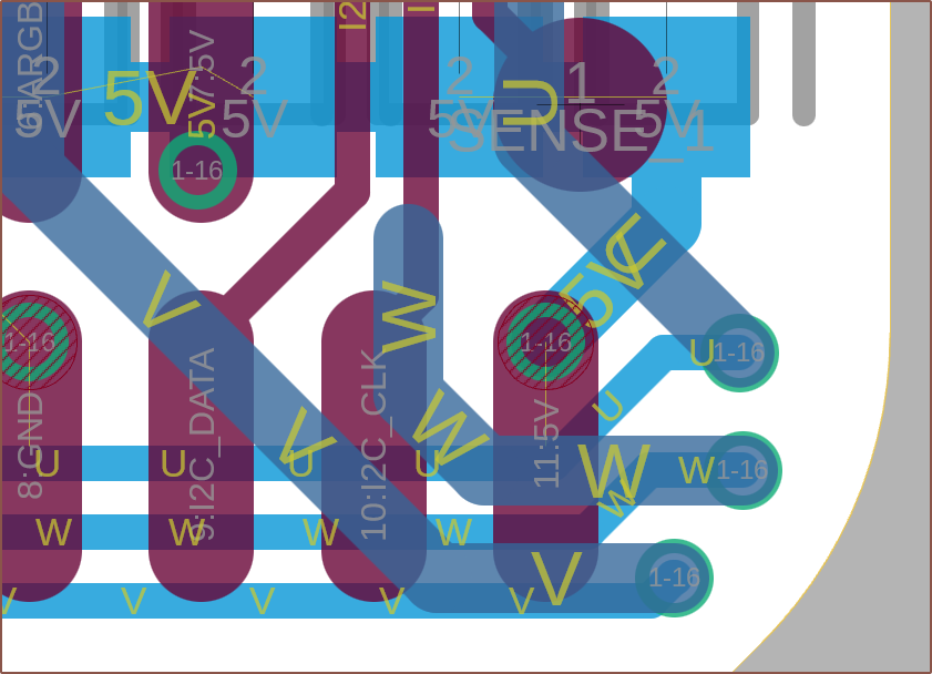
So then I had to move the DRV and it's bundled passives around to find a solution which I could tap out. After exhausting the search space for 90 degree options, I looked into diagonal placement and that's when a solution existed. The magnet sensor also needs a capacitor and an optional protection diode.Continued routing and was having space issues, and then I noticed that I wasn't using pin 5 on the 6701 for anything (it's the PUSH output) so I removed the pad:You can also see here that ARGB was easily routable because the VDD pin of the SF1 module was omitted.Unfortunately, I still didn't have enough space to place this via where I wanted it.Other than that, the PCB was looking like it was coming together nicely.
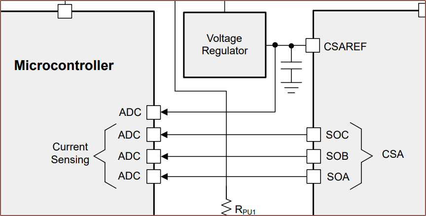
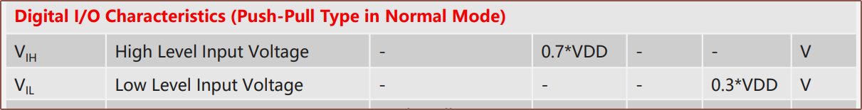
Something that I didn't see when I made the first PCB was that the CSAREF pin actually needs a reference voltage source and read by the ADC:
I decided to connect it the the 3.3V LDO, as well as the 6701 since its IO logic levels are derived from it:
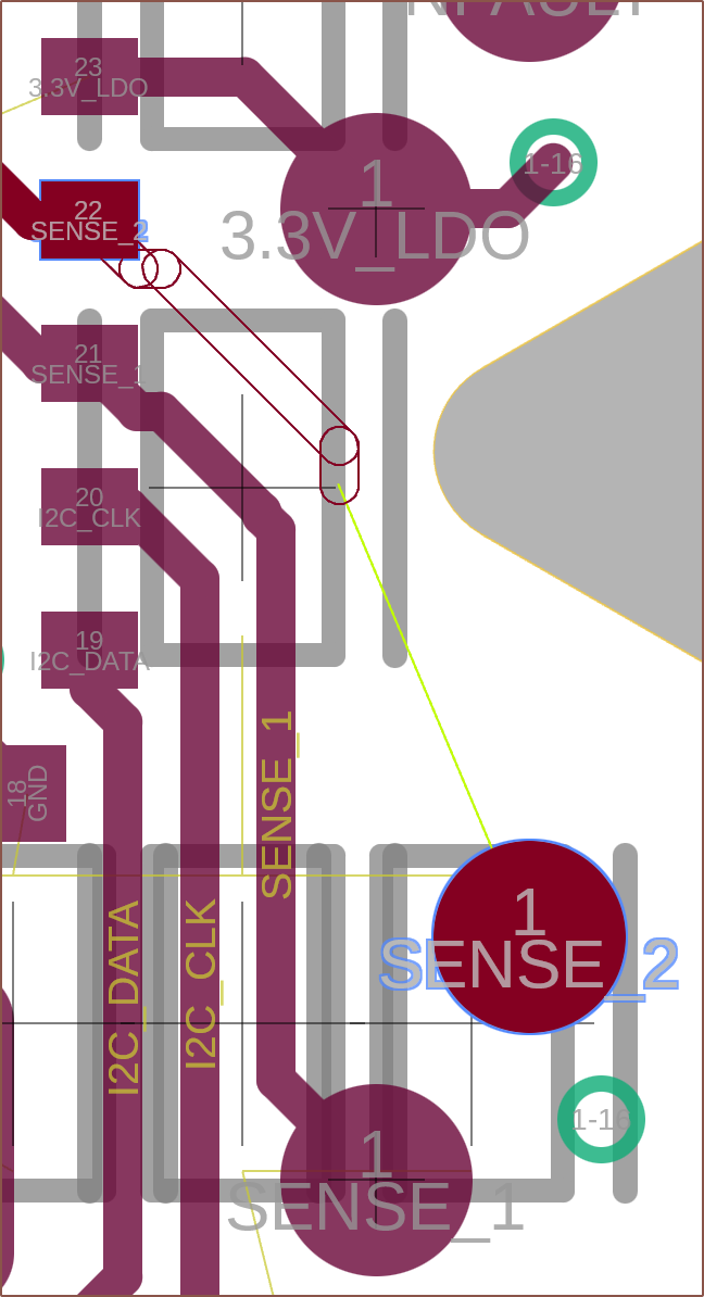
Routing pads
I had the idea of adding a spare "XTRA" pad since pin 25 on the SF1 was unused and right next to a potential pad location.
There wasn't enough space to route, so I initially used 0.16mm traces here. However, I decided to increase the radius of the cutout curve from 1 to 1.2mm and that was enough to fit 0.2mm traces:
Notice how I've tried to keep traces far apart if possible.
I was also able to improve the routing (and aesthetics) by moving the vias of the 11P to the top:
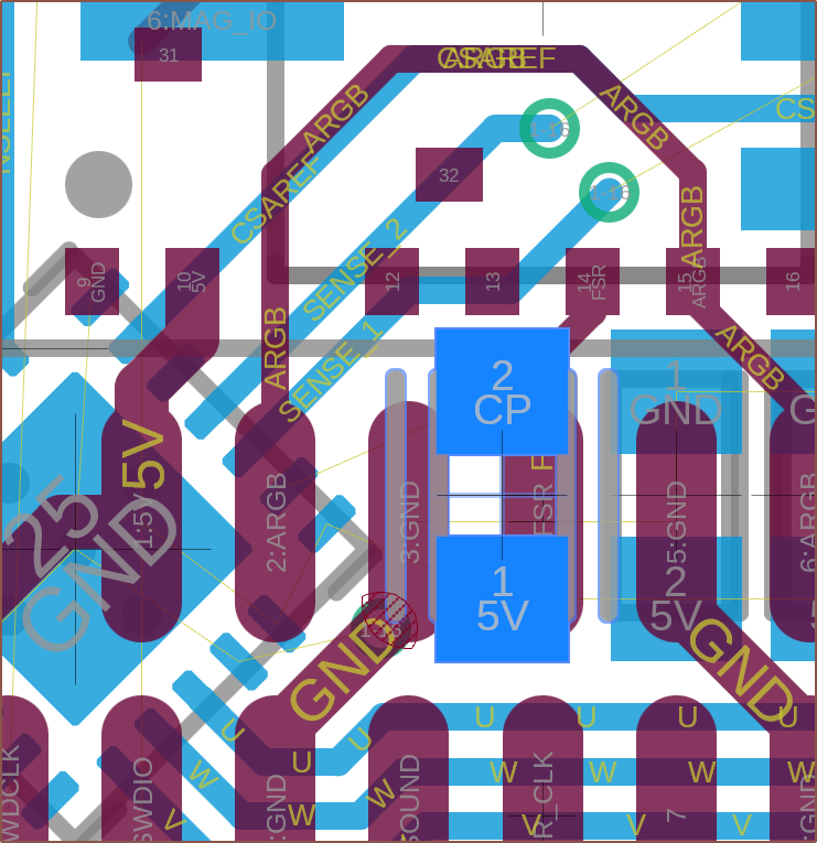
Lastly, I rotated the topmost capacitor and moved the topmost ground via down so that I have as much space as possible to add the UWV pads. Why "U, W, V" not the alphabetical "U, V, W"? Well W looks like double V's yet is called "double-U" in English, so it's like the blend of U and V.
Next Steps and Conclusion
Design UWV pad
Connect airwires
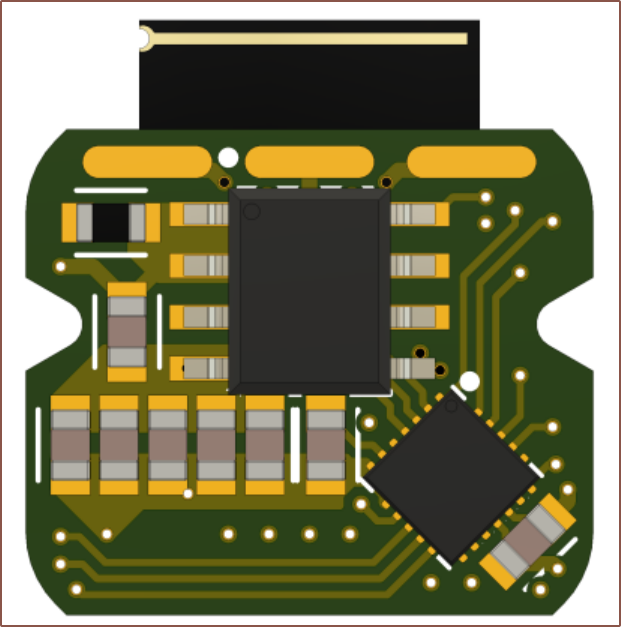
I think it's kind of nifty how a bluetooth BLDC controller could probably enter into the Square Inch Challenge and look aesthetically designed at the same time:
It's almost like one of those artistic PCBs I've seen in the past:
Flex of placement skill.
[14:15]
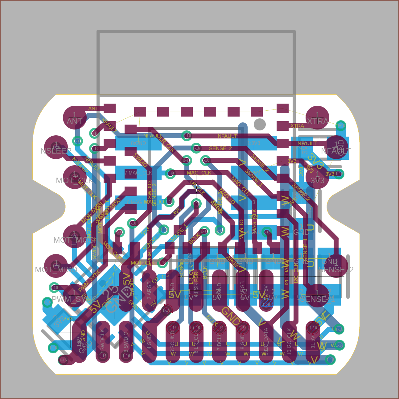
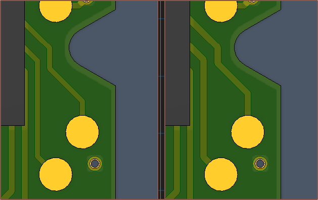
Fully traced and copper pours added
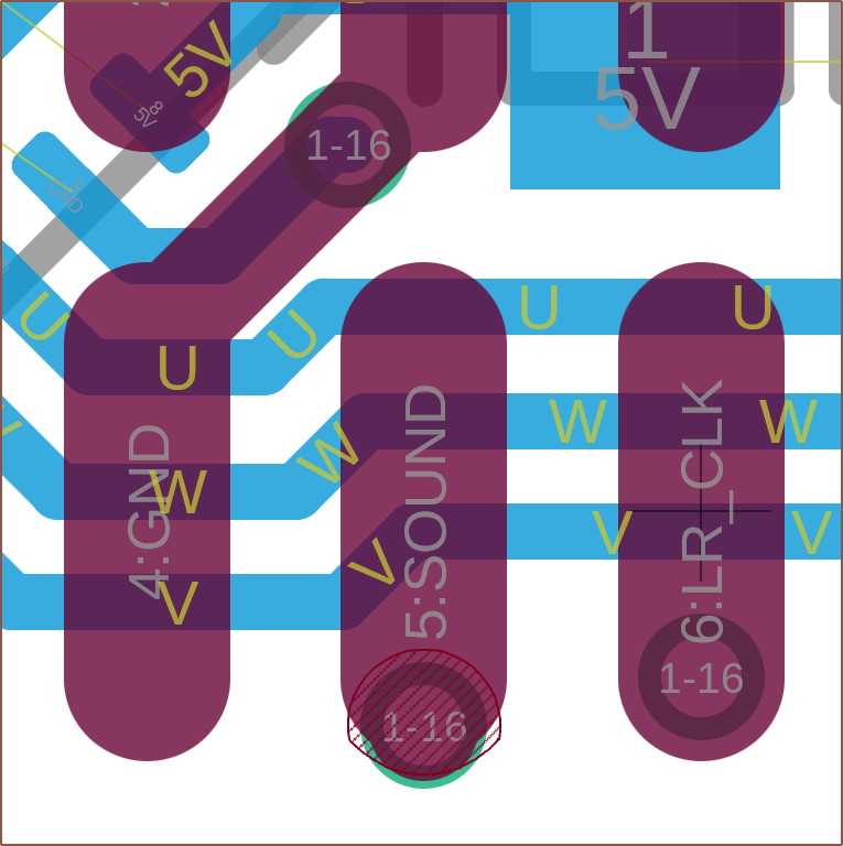
The pads are 3.2 x 0.8mm and are spaced 4mm apart. It's hopefully enough space to solder the 0.35mm wires. It isn't ideal that these pads are so close to the PCB antenna, but they look nice.
[Aug 3]
I've had to do some slight tweaks, such as
moving the silkscreen dot of the MT6701 off the UWV pad
spacing the CP capacitor from the 5V ones to prevent shorts during manufacture
replacing one of the 100nF 3.3V capacitors with a 5.1K pullup for nFault (recommended in datasheet)
It made little sense that two bypass capacitors were so close together, which would likely change the frequencies filtered out.
changing LR_CLK to use P0.18 as I found out that its frequency is dependent on the sound sampling frequency (e.g. 44.1kHz).
I looked into it, and the "low frequency I/O" note for the nRF52 is actually a caution for the radio, not the pin in question. From what I understand, the pins with the note are very close to the radio circuitry and frequencies higher than 10kHz could diminish performance of the radio. The GPIO will work completely fine.
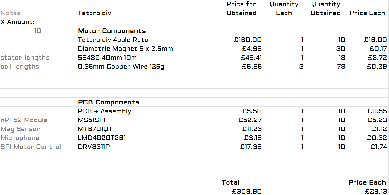
I still don't know how much shipping is going to cost, so I've just assumed that $16/motor + taxes = £16/motor. I've also just assumed that 10 PCBAs (including passives) would be £5.50 for now.
The motor part costs £20 and the ESC circuitry costs another £9. Looking at prices for the latter, it's probably respectable considering the feature list.
For ease of assembly, I've gone with a seemingly decent -26dB microphone from JLC's part list. It also costs 60p more, but I'm going to use the QFN package of the magnet sensor for the time being for the best chance of everything fitting.
I am also researching into O-rings and asking if the rotor bearings can be made waterproof. Why? Because Tetent and Tetinerary are expensive and I can't just RMA it or Amazon up a new one if a spill happens, nor do I want to have to live a life of babying the device.
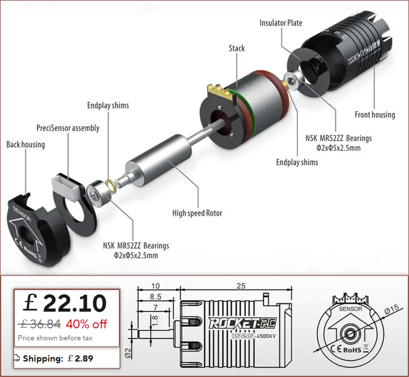
I happened to find a 15mm diameter BLDC that is used for RC cars. The other 15mm I found is called the 1410 and it's a similar size but the winding offerings are slightly different. The exploded view at least gives me some confidence that my motor design isn't doing anything out of place. The rotor is only 6mm diameter by 14.5mm long, however, as well as 2 pole.
Tetoroidiv-16 gets a Quick Stop force of 20.7mN, which should be enough to create virtual walls at speed.
I've gone through all the 16mm brushless motor datasheets to find the constant that converts Kt to KV, and this is the data I have so far:
9.375
9.4125
9.425
9.4257
9.5625
9.5583
9.5468
9.5523
9.4572
9.4589
9.4674
9.4174
The average here is 9.47 which converts between mN.m to V/kRPM. To convert to V/RPM, the constant would be 9470.
Due to the existence of 5PH belt, which should be 8mm wide, and 15mm wide FSRs, I did look into the possibility of using 5PH317 along with a 15mm diameter motor that has a 46mm rotor length. This length was chosen so that I could potentially use 50mm wide SS-430 foil.
However, because those 15mm wide FSRs have a 10kg range instead of a 500g range (implying lower resolution for sensing forces from 0 - 300gf) and because of this paper finding out that key spacing down to 17mm does not seem to affect typing speed, but 16mm, I don't think there are suitable benefits to try for a 15mm x 150mm Tetrinsic.
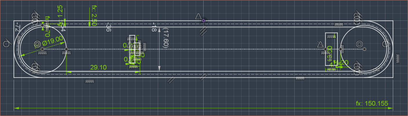
The following rotor design has seemed rather stable over these past few weeks so I've sent it to the rotor supplier:
I like how a few notable dimensions are divisible by 9. The rotor inertia is 1.65g.cm^2.
The XIAO Sense boards manage to fit a microphone, and since I'm looking into ANC for Tetinerary, it makes some sense, especially since the Tetrinsics are planned to be infront of the ear.
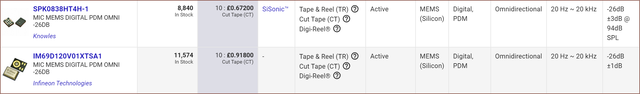
I wasn't able to find anything decent for a decent price on JLC's part library, but I have found 2 sub-£1 options on Digikey that have the full 20 - 20,000Hz of range and relatively high SNR ratios along side a -26dB sensitivity. According to the Infineon datasheet, this allows capturing the full dynamic range with 16-bit PDM, which is the max the nRF52833 supports. Coincidentally, the 833 samples at 16kHz, just like the proposed speed of the Field Orientation Control loop.
Digikey's XENSIV page was the first thing I found on my search and the IM69D120 does seem like the best option, with a 69dB SNR.
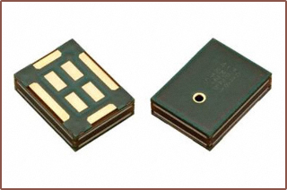
The SPK0838HT4H is cheaper and has a 64dB SNR, which seems more typical as most others I've seen are 60, 63 and 64dB. It also has the mic port on the top instead of the bottom, and unlike most, doesn't seem to have a shield and seems to be made out of PCB:
There's also the IM70D122 which has a similar but not identical footprint and has IP57 water resistance.
These microphones need 3 pins, meaning that the PCB would need 19 / 20 available GPIOs.
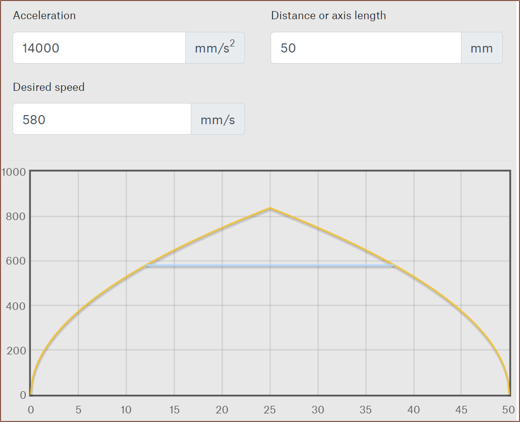
So I had the idea to actually create a simple PowerPoint animation where the orange bar would slide up and down 50mm with a smooth start/end transition to account for acceleration. Then, the time duration of both the animation and the transition to the next slide would be changed so that it looks like my finger is actually moving the slider. I found that a 0.12s animation and 0.14s slide transition achieved this without my finger doing any particular effort.
Then I finally used the SUVAT equations in the real world for once and I got an accel value of 13.89m/s^2. Since all these measurements are kind of rough, I stuck with 2 significant figures thoughout, thus I used 14m/s^2 for my calculations.
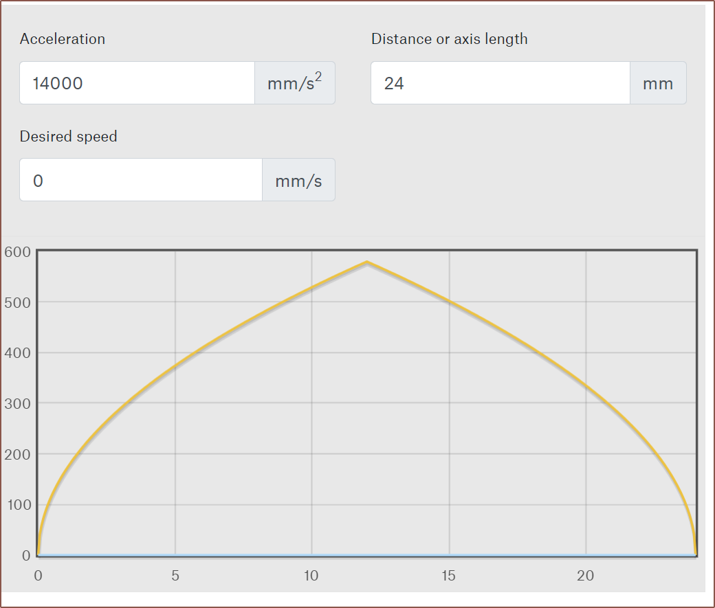
I then used Prusa's calculator to graph out the speed profile when doing the expected max typical movement of 24mm (each column in the Tetent layout is 6mm apart):
I confirmed that it was 580mm/s. If you're wondering, the peak finger movement from end-to-end was 833mm/s.
Dividing this by the circumference of the 16mm pulley, converting to RPM and then multiplying by the gear ratio and I got 5000RPM to 2sf.
This is a bit of a problem because I still need to be able to generate a virtual wall force at these speeds, such as if the finger starts to accelerate and then hits the virual wall halfway through the movement.
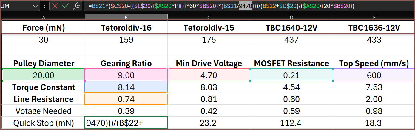
After spending a while deriving the correct equation, it's not looking good at 5KRPM:
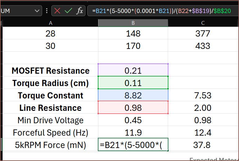
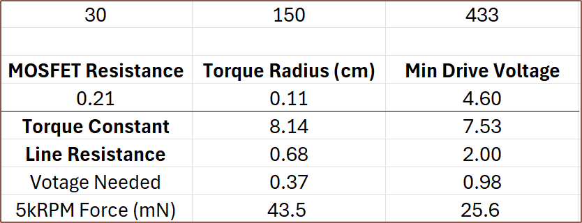
The equation used. A more complete equation is further down in the log.First row is rotations per second whilst still providing 30mN and the second row is the force applicable to the belt at 5kRPM if positive.
Understandably, negative values all coincide with all motors with a torque constant over 10. For example, I needed to go to the TBC1636-12V to get a non-negative force of 37.8mN and that configuration uses 44% more power than the 24V variant.
Finding the max turn count
10 > 13.77x / 38
380/13.77 > x
27.6 > x
Turns need to be 27 or less.
I did also consider just having a higher drive voltage that would sidestep all of this, such as running the motor at 9V, but that may complicate electrical matters (not like running a motor on the same 5V rail as logic circuitry is a smooth sailing idea either) since it would be nice to have everything fully contained on Tetoroidiv.
Actually, as I'm typing this, I'm checking motors to make sure everything is all correct, and it's not. For starters, a 1656 motor snuck into the data. Additionally, assuming 0 voltage drop on the 5V rail is likely inaccurate. All this happened way past when I usually go to sleep because, as they say, "I don't need sleep, I need solutions!"
Anyway, 0.25mm wasn't going to make it, and since I can only have discrete coil heights, it meant that I started looking at the 0.3 / 0.35 / 0.4mm wire options. I was going to write this log talking about how power consumption has gone up 180mW just so that I could get a configuration that still had torque at 5kRPM, but I guess the sleep assisted because I've just tried a 0.35mm 21T option:
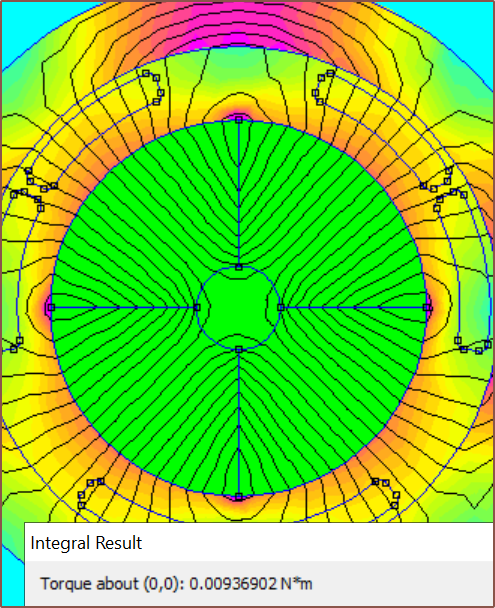
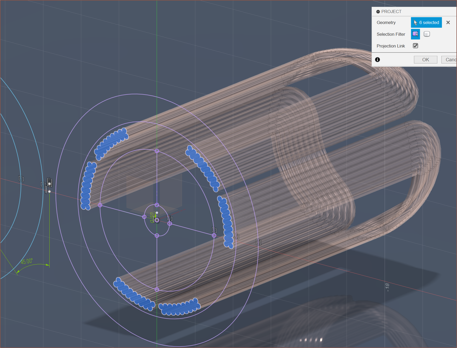
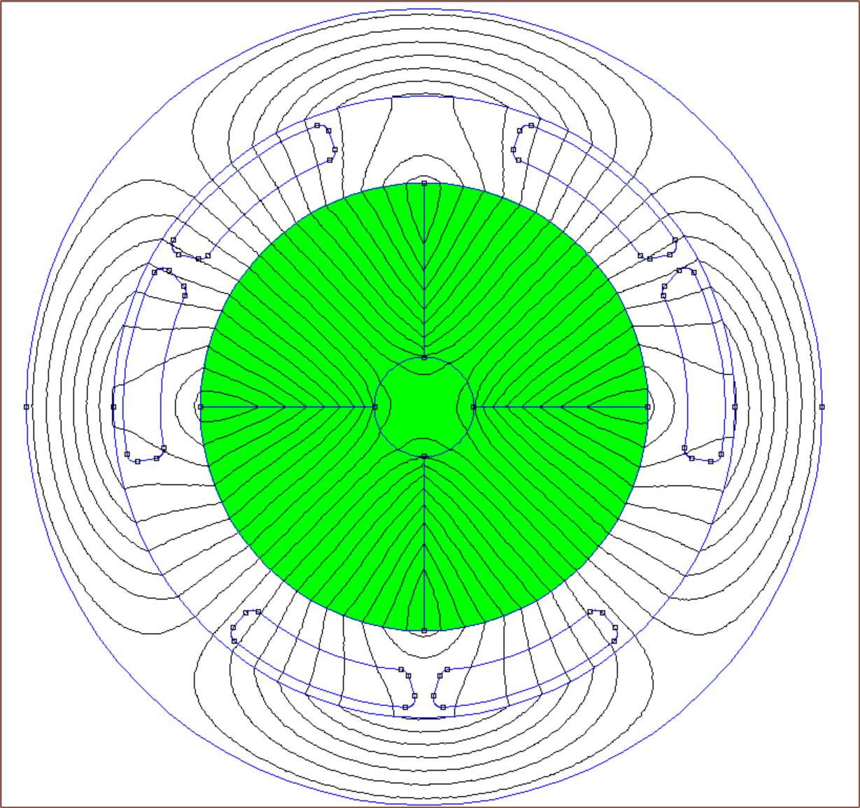
For 0.3mm and above, there are only 2 rows of wire CSAs, meaning that I don't need to extrapolate how many turns will fit.Simulation with 9mm rotor and 21 turns, and the other magnet oriented to maximise the KV of the motor.Toroidiv against the TBC1636-12V
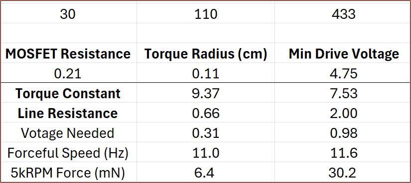
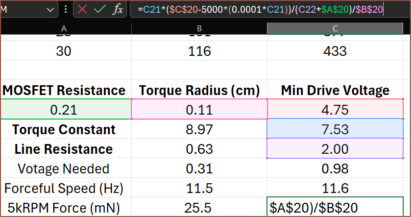
110mW is the all-time lowest power consumption I've witnessed. Considering my fingers would likely be in (what the enthusiast 3D printing group calls) "sensorless homing mode", 6.4mN should be enough to set a speed limit and decelerate my finger enough to reduce the EMF enough so that the motor can apply the full torque. I'm not going to risk it though and would rather use 20 turns; the max power goes up by 6mW but the max force on the belt goes to 25.5mN at 5kRPM.
A more complete equation to calculate the force exerted on the belt. It calculates the back-EMF at 5kRPM, which is subtracted by the minimum drive voltage. This is then divided by the total resistance to obtain the current. Next, this current is multiplied by the torque constant to obtain the torque generated by the motor. Finally, this is divided by the torque radius to get the force on the belt.
I believe that a 580mm/s speed limit would probably go unnoticed:
The finger should spend about 45 milliseconds at that max speed. This is about 1/3rd of the entire motion time, with the acceleration / deceleration taking 41ms. In total, it's 127ms.
I checked all configurations of the brushed 1640 and none can provide torque at 5kRPM, meaning that the 1742 is the only brushed option at the moment. Currently, none of the commercial options are even close to the custom-designed solution, with the explanation for the BLDC options likely being because they only have a single pole pair.
Green is brushless and copper is brushed.
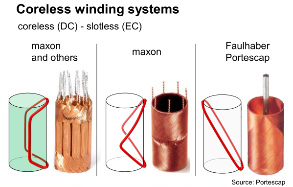
Another explanation is because these motors are usually made with windings such that they're self supporting, but it means that the wires themselves usually don't run perpendicular to the movement of the permanent magnetic field thus only a component of the total actually creates torque:
It's still more likely to be the pole pairs though. For example, if the TBC1636 had 2pp instead of 1, the power consumption would theoretically be 108mW.
[May 21]
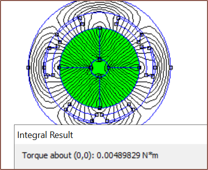
I found out that the simulation is somewhat unreliable, in that changing the spacing between coils by tiny amounts would affect the torque integration substantially. For example, I'd get 6.76, 7.37 and 5.3 for 3.8mm, 3.6mm and 3.4mm respectively. It did seem though that values typically decreased on either side of 3.6mm.
I tried things like modelling with a more accurate CSA (see below), and got 9.7 for 19 turns but 2.3 for 18 turns, so there was certainly something mysterious going on.
So then I tried an ultra-simplified CSA, where I got 6.8 and 4.9 for 3.6mm and 3.61mm respectively. The stars aligned when I used
This is spacing of 3.61mm
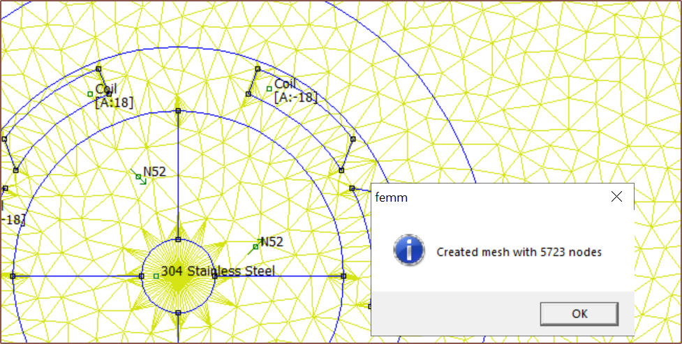
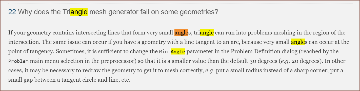
I looked into my problem settings and started tweaking values to see if anything made a difference, and min angle certainly did:
Minimum Angle = 1Minimum Angle = 30
So I looked it up and this is what I found:
That might explain why the BLDC tutorial dropped the min angle to 20, which is what I had it set as.
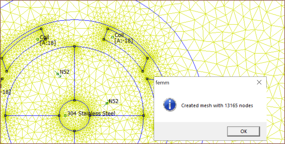
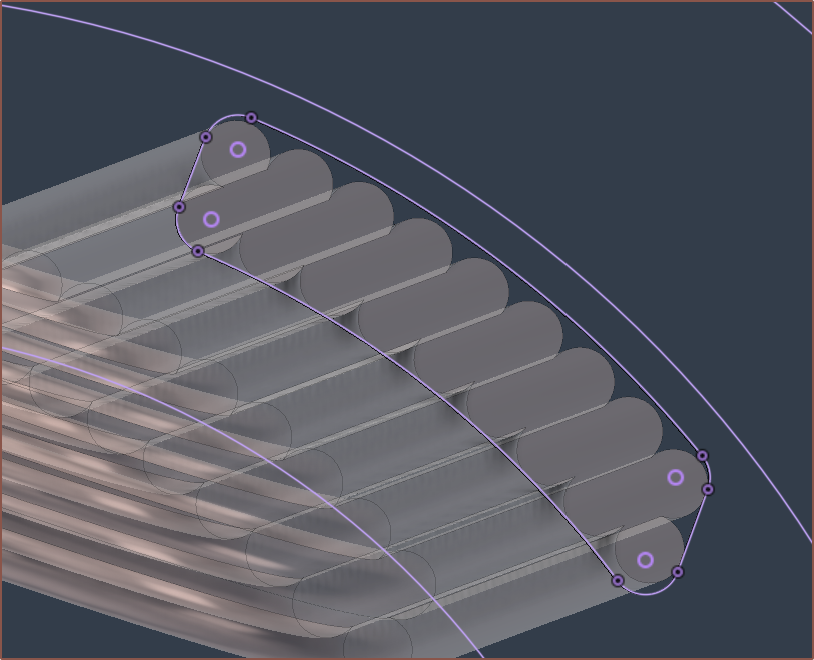
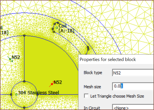
Thus, I went back to a rounded-edge CSA and started trying out different mesh settings for the air (inside the motor) and yoke, and I found that a mesh size of under 0.1 gave results that were reliable enough (+/- 0.1 torque constant).
Rounded edge CSA. I misread the "line tangent to an arc" part because of the "put a small radius instead of a sharp corner", but it seems fine enough.Experimenting to see if larger or smaller sizes get a finer mesh.Mesh size of 0.08 for the air and SS-430.
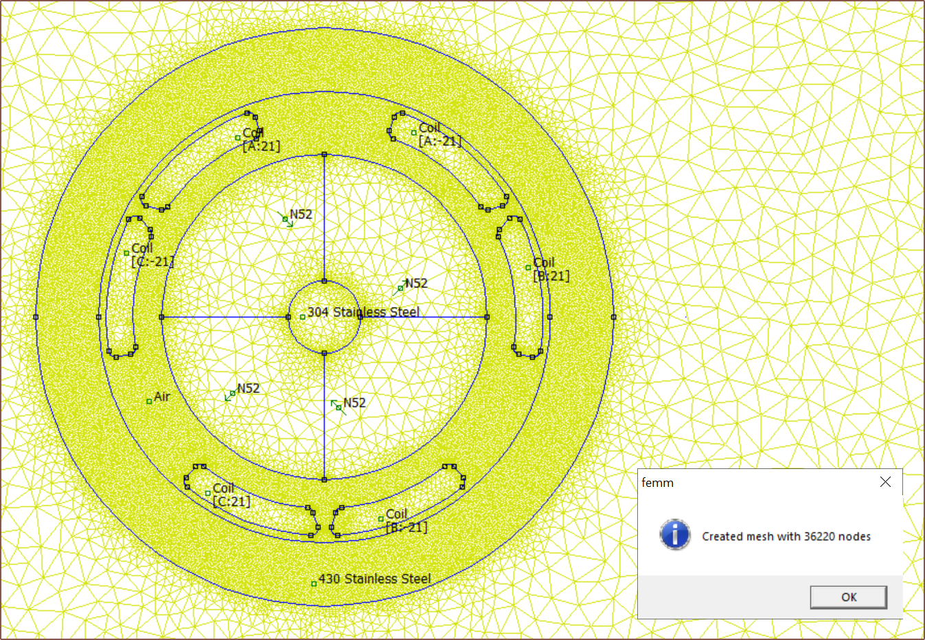
I also learned that I didn't have to generate the mesh before solving, as FEMM does that automatically. That means that I don't have to deal with the performance penalty of displaying so many nodes. Alternatively, I could always toggle "Mesh -> Show Mesh" in the top bar.
The solve takes maybe an extra 5 seconds but the flux lines look much smoother and, as mentioned before, the result is more stable.
This is with 21 turns and a torque constant from a simulation using a 0.05 mesh size. Since the USB spec usually allows down to 4.5V, I've calculated with 4.6V minimum drop. The higher the allowed voltage drop, the smaller a bulk capacitance I need.
 kelvinA
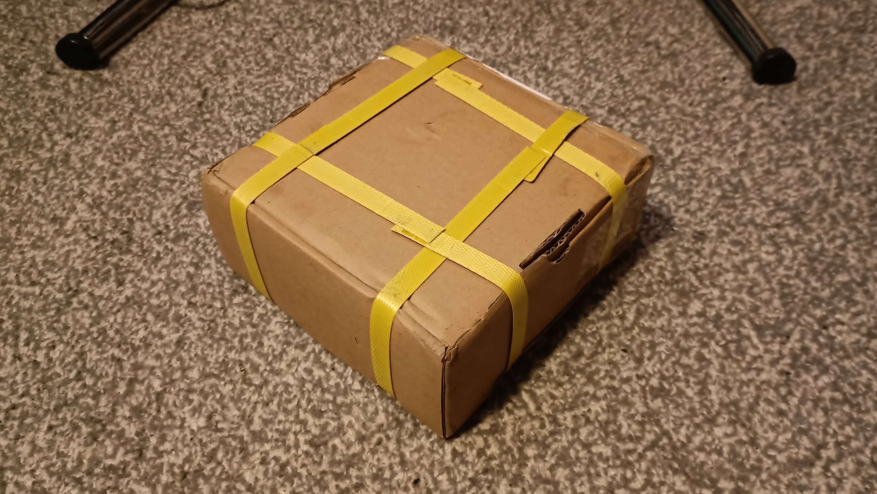


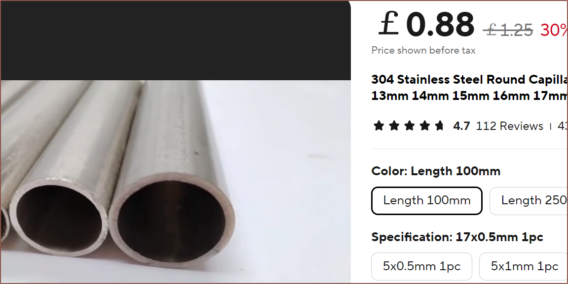 I've modelled in a 49.5mm tube so that I've got some cutting tolerance:
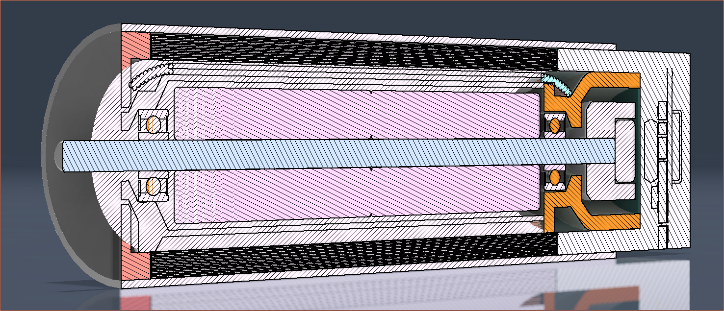 I'd also like to avoid needing a semi-circle cutout for the silicone PCB assembly, but I don't have confidence I'd be able to get away with it. Oh, but I wouldn't be able to do that anyway or else I'd block the BT signal entirely.
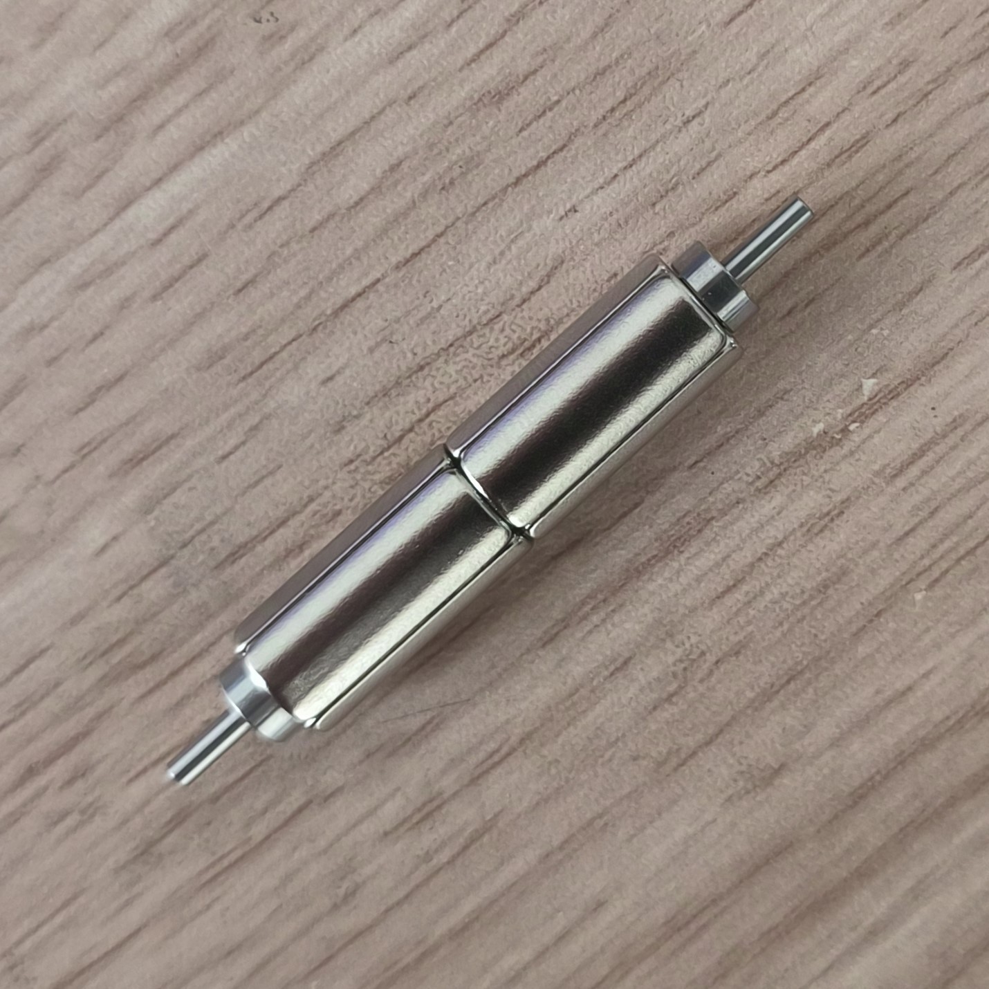
 I've finished modelling the front cap (chalk red), the front of the overmould, the back bell (orange) and the silicone moulding that holds and protects the PCB. Somewhat surprisingly, mounting the PCB is easier because of water ingress protection.

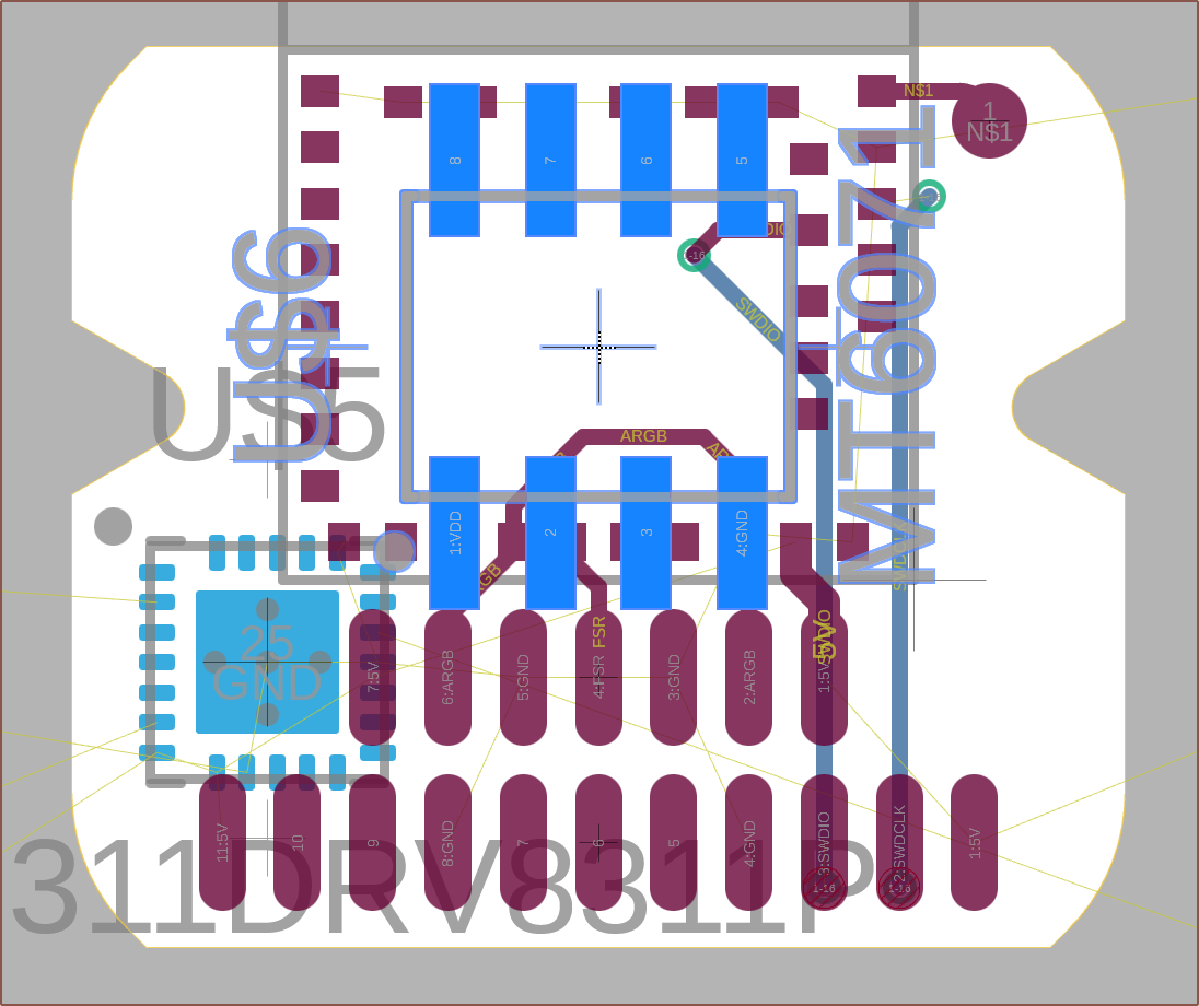 So then I had to move the DRV and it's bundled passives around to find a solution which I could tap out. After exhausting the search space for 90 degree options, I looked into diagonal placement and that's when a solution existed. The magnet sensor also needs a capacitor and an optional protection diode.
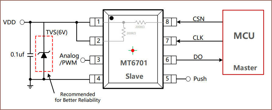
 Continued routing and was having space issues, and then I noticed that I wasn't using pin 5 on the 6701 for anything (it's the PUSH output) so I removed the pad:
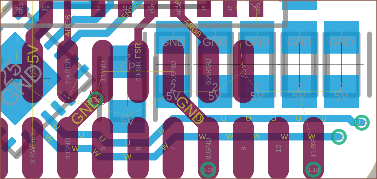

 I still don't know how much shipping is going to cost, so I've just assumed that $16/motor + taxes = £16/motor. I've also just assumed that 10 PCBAs (including passives) would be £5.50 for now.
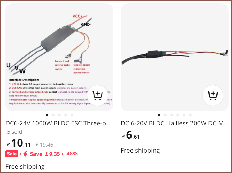
 So I had the idea to actually create a simple PowerPoint animation where the orange bar would slide up and down 50mm with a smooth start/end transition to account for acceleration. Then, the time duration of both the animation and the transition to the next slide would be changed so that it looks like my finger is actually moving the slider. I found that a 0.12s animation and 0.14s slide transition achieved this without my finger doing any particular effort.