 Elbert
My family has a few hours of super 8 film of my youth and before. I would like to digitize them. OK, there are already some project to digitize super 8 film reels. But this method I am already thinking of for more than 10 years now. The method: I use an USB microscope to make a picture of every frame in the real and use stepper motors to forward the frame.
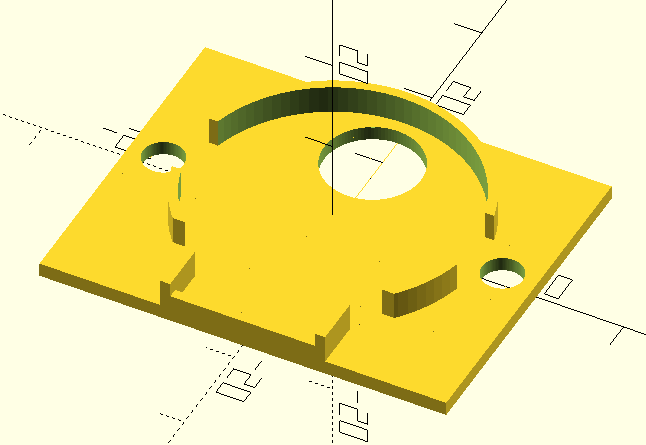
My first prototype was made a long time ago with wood and some (fake) Meccano. This was too inaccurate for its purpose, so the project halted. After I got my second 3D printer for larger prints, I started to think to revise this project. Although 3D-prints are more accurate, still some parts had to be more precise. I used the metal parts from a manual film viewer/editor in combination with stepper motors.
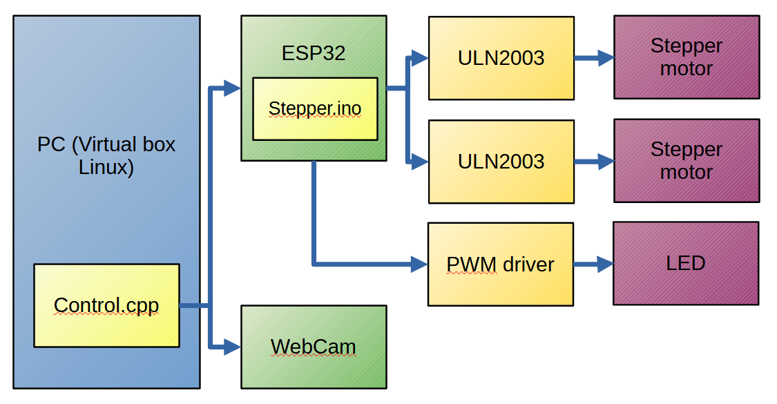
These stepper motors are controlled with an ESP32 connected to an PC, which also reads the USB microscope. The individual pictures are converted to a movie clip using ffmpeg.


 GOAT INDUSTRIES
 Aaed Musa
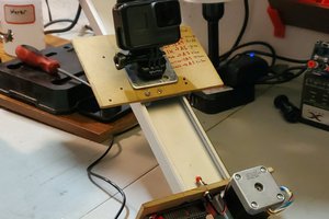
 Victor Frost
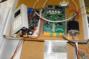
 Duane Degn
Do you take multiple images of each frame to HDR the film?