Martynas
-
Testing
06/23/2024 at 17:17 • 0 commentsMy test setup with Analog Discovery 2.

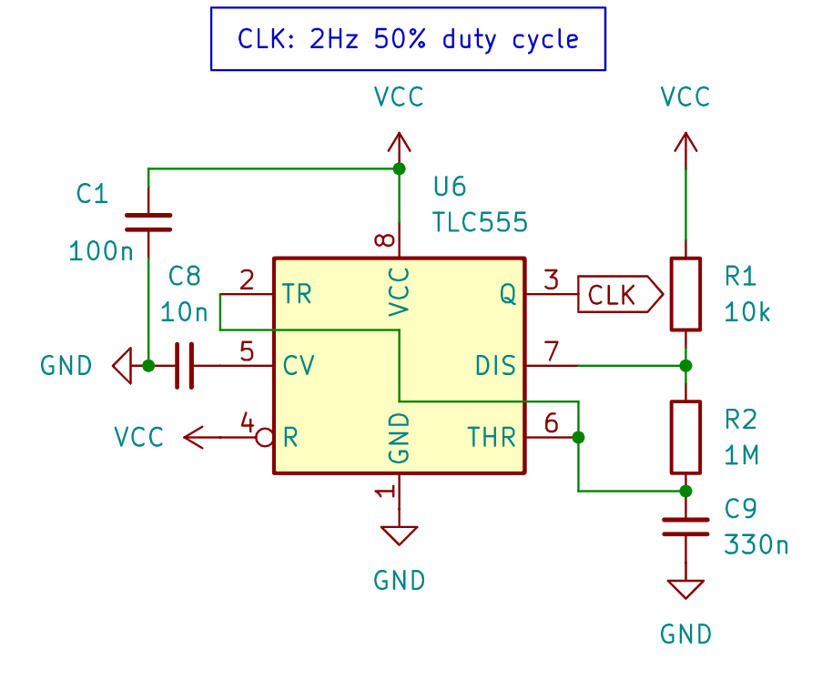
Measured CLK frequency is 5.75 Hz and duty cycle 50.4%
Current consumption from 5V power source (without any load) on average was around 2mA.
Video shows circuit operation with different loads:
- On-board LED
- 5V LED strip
- 12V neon bulb
-
Assembly
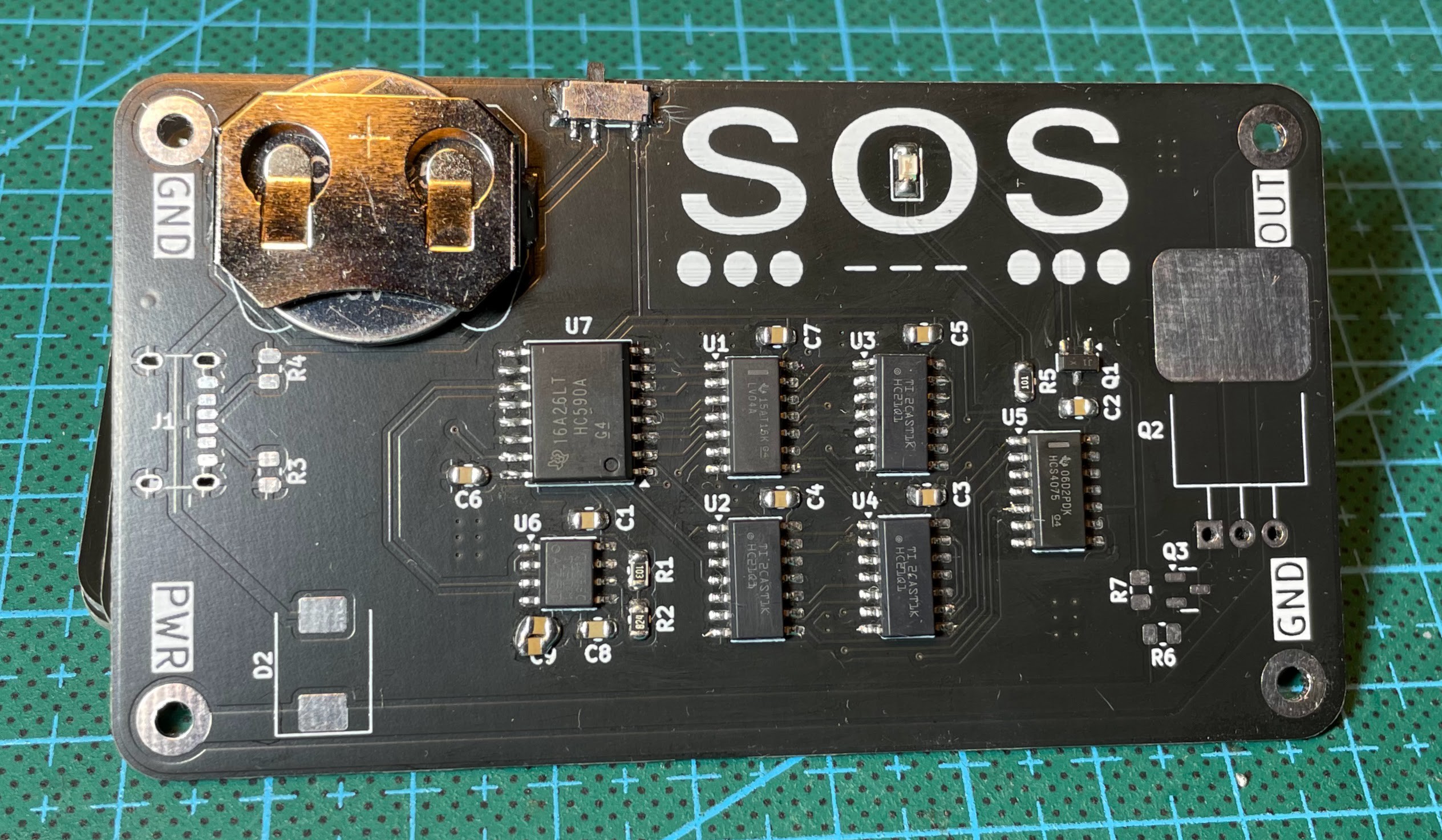
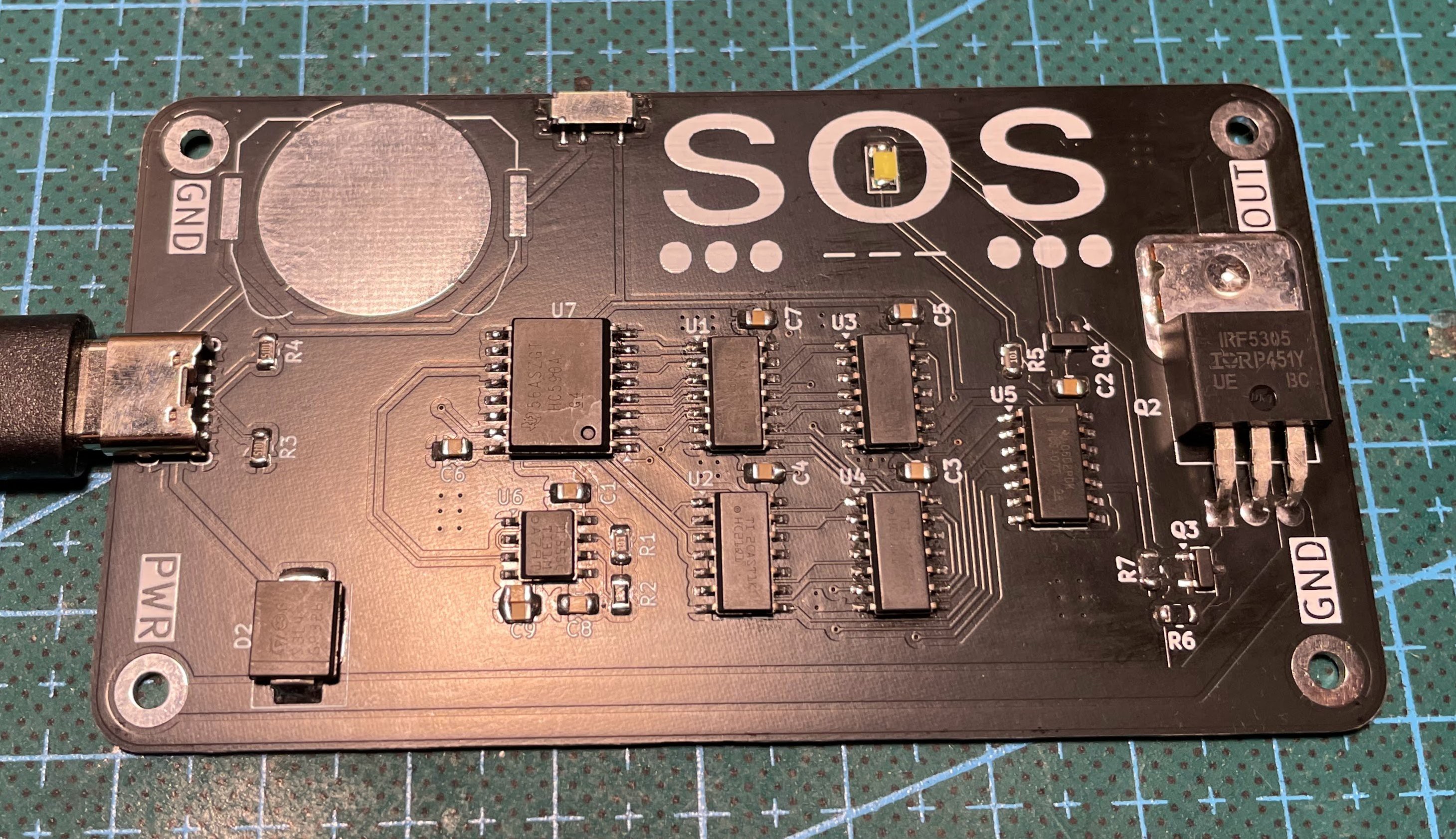
06/21/2024 at 09:51 • 0 commentsPCBs finally arrived.
Noticed some issues while soldering:
- Coin battery holder should be flipped. It is difficult to insert battery if USB-C socket and CC line resistors are soldered.
- Turns out I don't have any 330nF 0805 capacitors at hand for C9 and no 1M ohm resistors for R2. It is needed for setting 555 timer frequency to 2Hz. I soldered two 100nF in parallel for C9 and 620K ohm resistor for R2 instead. This should give 5.8Hz frequency.
- I don't really know why I chose 2.5mm holes for corner connections. I think 3mm holes would be better.
I have soldered two PCBs. One powered by coin battery and driving small green LED.
Another powered from USB-C and driving brighter white LED with possibility to connect external load.
Board thickness is 5.7mm (PCB 1.2mm + TO-220 4.5mm).
-
Project Cost
05/31/2024 at 21:01 • 0 commentsMost of the components were ordered from DigiKey, some from LCSC and some I already had.
I added single component prices from DigiKey to BOM.csv file.
All components needed for one board totals to ~12$.
I ordered PCBs on JLCPCB service with minimal quantity of 5 and all standard features. Total price was 2$.
So one business card costs around 14$, this doesn't include shipping cost and taxes. -
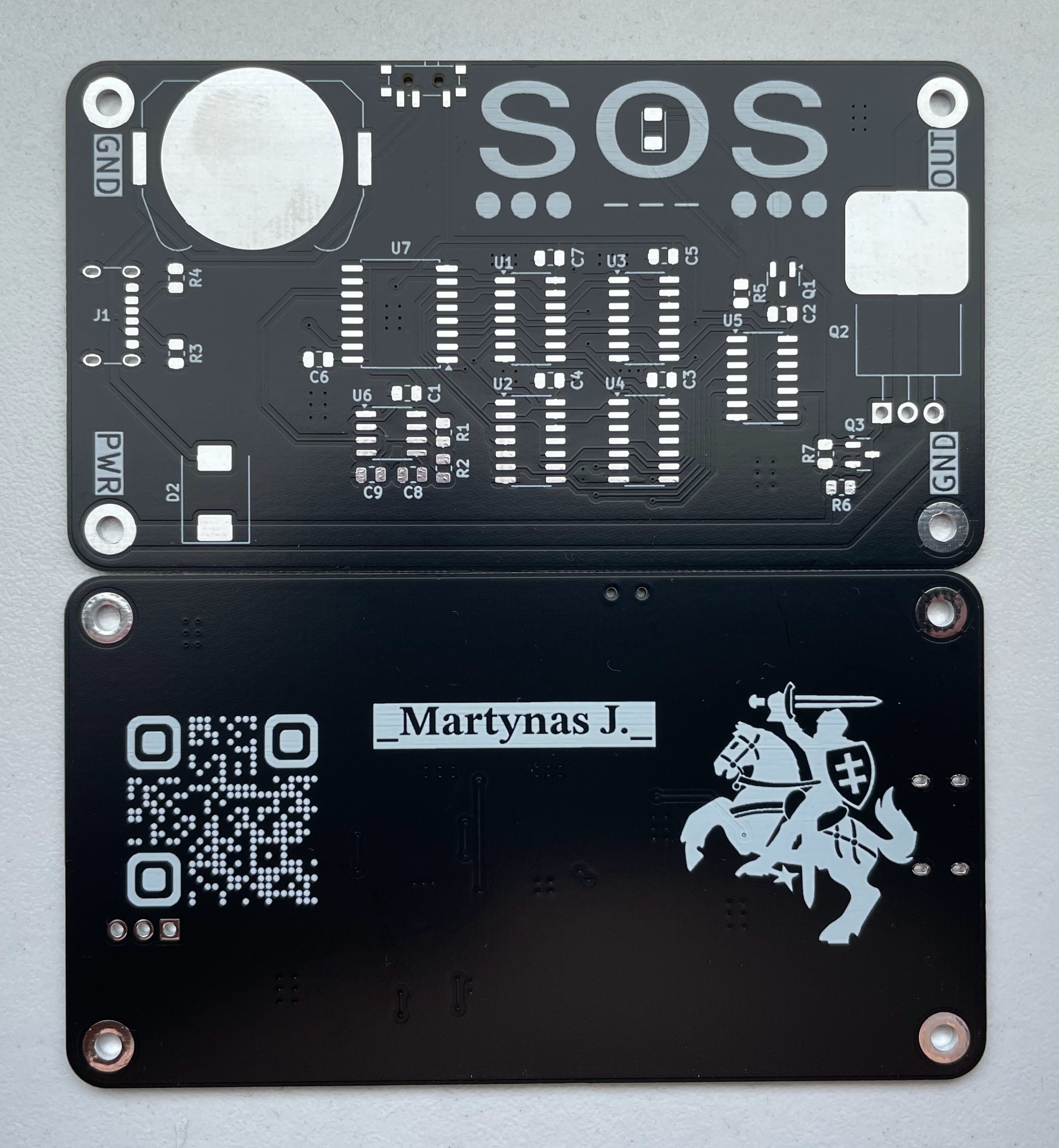
PCB Design
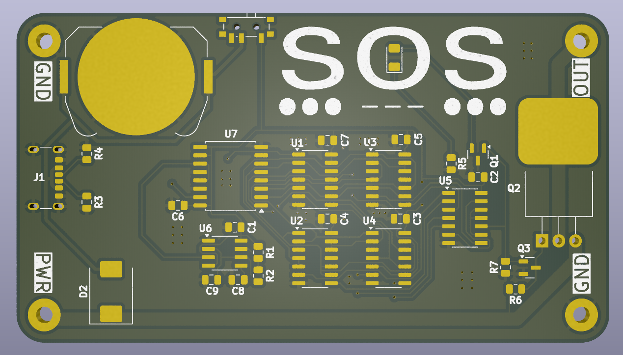
05/31/2024 at 20:50 • 0 commentsPCB designed using KiCAD. I tried to use SMD as much as possible, for ICs - SOIC package and for discrete components - 0805 size package.
Check schematics.pdf for full circuit schematics. There are some custom symbols and footprints used in this project. Those can be imported from this github repository.
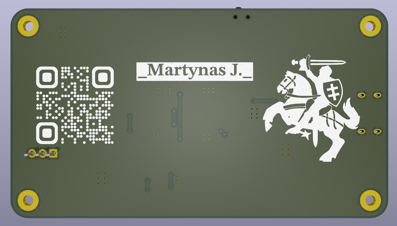
PCB is dual sided with most of the traces on top layer. Bottom layer dedicated for business card stuff - name, barcode which points to my github and artwork.
I ordered PCB on JLCPCB with black soldermask and board thickness of 1.2 mm.
-
Power and Output
05/31/2024 at 20:34 • 0 commentsCircuit will have 2 power options:
- CR2025 coin battery
- USB-C 5V@3A
USB-C socket CC lines are connected to ground via 5.1K ohm resistor. This tells power source to supply 5V on VBUS line. Most ICs I chose have maximum supply voltage of 6V.
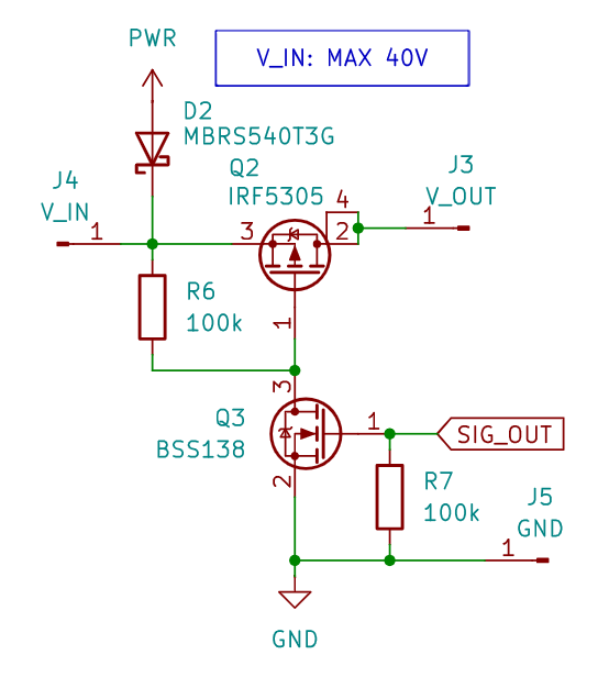
The circuit will have a small on-board LED for SOS signal output. Additionally, a high-side PMOS load switch can be connected to a larger load, such as a 12V lamp. An external power supply with a maximum of 40V will be needed for this.
-
Clock Circuit Design
05/31/2024 at 20:15 • 0 commentsFor clock signal I'm using 555 timer. There are lots of tools online for calculating 555 timer circuit parameters. I used 555 Astable Circuit Calculator for this.
General rules are:
- choose R2 value much higher than R1 for 50% duty cycle;
- C9 sets clock frequency. 330nF capacitor will generate 2Hz signal. To increase frequency, decrease C9 value.
For generating 5-bit logic circuit input signal we'll need binary counter. It will divide clock signal frequency by 2/4/8/16 and so on.
Full circuit simulation with 555 clock generator, binary counter and logical circuit was done using Falstad. Click here to access it.
SOS Business Card
Business card that generates Morse code SOS signal using discrete logic components.