-
Latest resources
07/02/2024 at 13:30 • 0 commentsHere are the latest resources we've used:
LED 8x8 Dot Matrix MAX7219 Arduino Tutorial - Elegoo The Most Complete Starter Kit (youtube.com)
How To Configure and Pair Two HC-05 Bluetooth Module as Master and Slave | AT Commands (youtube.com)
Pixilart - Free online pixel art drawing tool
MAX7219 LED Matrix Display Arduino Tutorial (4 Examples) (makerguides.com)
Matrice LED Max7219 : tuto avec exemples de code Arduino (passionelectronique.fr)
Configuration du module bluetooth HC-05 pour arduino - Retro et geek
Your Arduino communicates with the HC-05 module • AranaCorp
How to Wire and Program a Button | Arduino Documentation
Arduino Turorial: How to use a button with Arduino Uno (youtube.com)
-
Bluetooth insted of radio
06/14/2024 at 12:31 • 0 commentsTo communicate between the different arduino we first used radio modules. The problem was that the distance to send information was not long enough, and some interference with the motors was possible.
We finally decided to choose the bluetooth module HC-05. For that we need two of theses modules, one master with the controller, one slave with the robot. We first configure the differents modules. The wiring can be seen in wiring diagram called "bluetooth module communication diagram".
The bluetooth module beside giving more range to our controller it gives more stabillity to our communications.
-
Power supply problem
06/12/2024 at 13:34 • 0 commentsThe four motors needing a lot of power needded to be appart from the supply for the other components. This needded to be done because of the interference from the motors to the radio transmitter and receiver that made then not receive the orders from the controller.
To do that we implemented an other power source with a battery, the battery gives the energy to the other components like the radio transmitter and receiver, the buzzers and the led screen for exemple.
-
Losing my head
05/30/2024 at 07:20 • 0 commentsI had to think of a way to attach the head to its body now. Again, it was quite the struggle to find a suitable idea mostly I wanted to keep the half sphere design I made of the head.
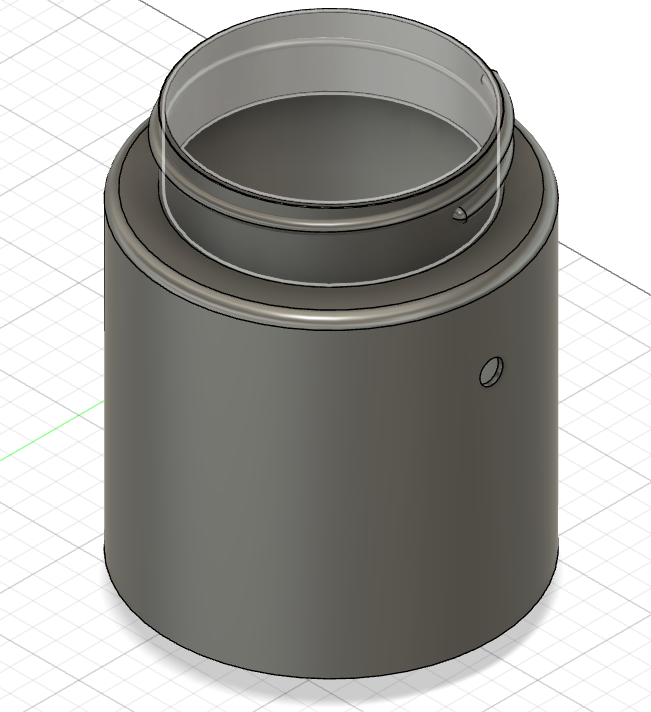
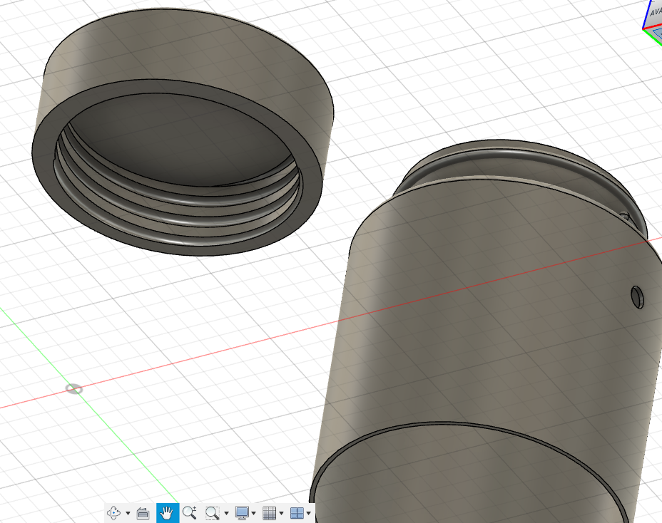
At the end of the day, I came up with the idea of using the "Thread" function (filletage) to attach the head to the main body. Basically, the head would be the equivalent of a bottle cap.
In order to do so, I had to design to cylinder that would be the body and the bottle cap together, which I did by following this video :
The particularity of this tutorial is that it doesn't use the fillet function but rather the spire function around.
It eventually came out like this :
-
When things started to get complicated
05/30/2024 at 01:20 • 0 commentsAt this point of my design, I wasn't really following any plan nor was I thinking of the final resulat of my model where I would have to print it, while also taking into account every other details such as incorporating the electronics components or assembling the parts together. I just had a general idea of what the model would look like but obvioulsy, I knew my job wasn't just done already like that. But by doing that, it helped me visualize the lookalike of our project's result and also gave an approximation of the mass of the object that I was going to print out.
Now I had to think more in details while taking the constraints into account. The scale, the measures of the components, how should I assemble the differents parts of my robot, how should i attach the wheels to the legs. All that needed to be thought of.
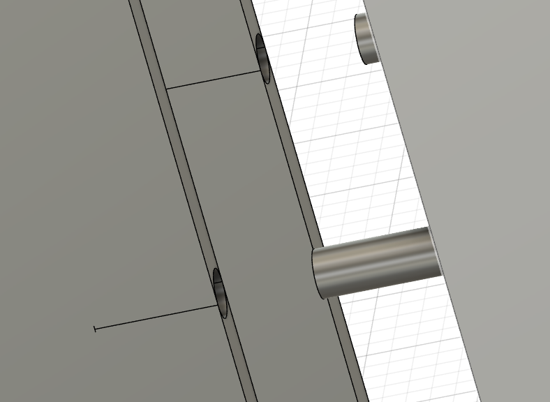
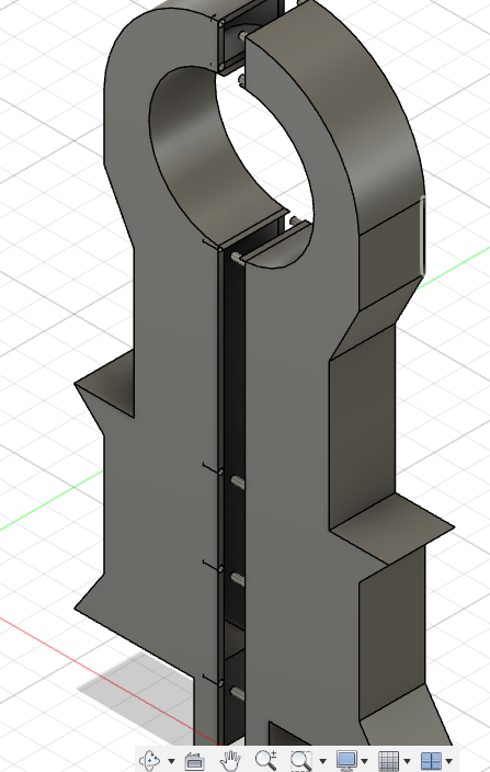
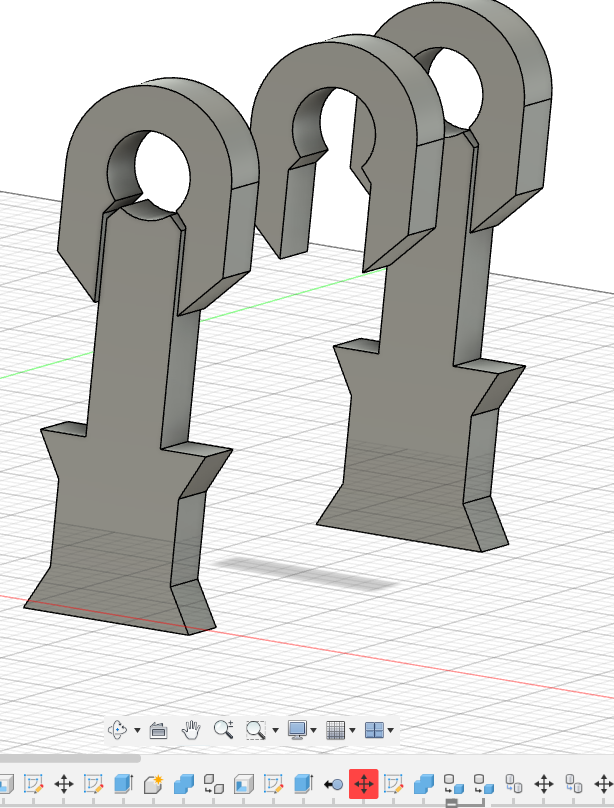
I started off by revisiting through all of our components and their dimensions, and how they'd be placed in our robot. And one of the main issue was to think of a way to attach the wheels and the motors to the legs. I first thought of simply cutting a compartment in order to fit the motor with the wheels attached to it but the combination of these 2 objects created a shape that was just quite impossible to design so that it can fit through. I struggled for quite a while to find an idea to place the wheels and finally i came up with the idea of splitting one leg in 2 creating some sort of coffin that would the motor in place. A picture is worth a thousand words so here's what I imagined and how I designed it :
I also found a video that explained how I could split the body in 2 and then create an assembling method by "clipping 2 bodies" using a male-female assembling method.
-
Starting to modelize the differents limbs of our droid
05/30/2024 at 00:42 • 0 commentsI divided R2D2's body into 3 main differents parts that I would have to design :
- the arms/legs (or whatever limb it is on a droid)
- the main body (which is basically just a cylinder)
- the head (which is basically half an empty sphere)
(plot twist : it wasn't that basic after all ... obviously ...)
Separately they were pretty easy to design.
Those were the legs that i designed by drawing a simple sketch that I found resembling enough to R2D2, and then simply extruded them.
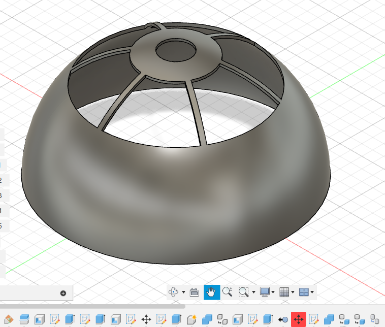
I then managed to design its head by following a simple tutorial on Youtube. The idea was to create a sphere that would cut in half and then draw a sketch that you would extrude bu cutting through the other half of the sphere to create these patterns.
For the main body, I simply created a cylinder.
-
First weeks of my attempts to modelize R2D2
05/30/2024 at 00:07 • 0 commentsThe first 2 weeks were mainly dedicated to research and documentation on the internet in order to visualize what kind of objects and shapes I was going to design. I watched many videos on how people would start off their modeling, and after watching most of them, I just realized that I would never be able to recreate what they did simply because it was too detailed. And tbh, we're not looking for designing the most detailed R2D2 we've seen, as long as it is recognizable enough. Here's an exemple of the videos I watched.
Even though the tutorial itself didn't help me much, I was still able to use the file linked in the description that allowed me to have an overview of what I was aiming for, and as well as something to compare my later design with.
That's how I started my design, without following any tutorial, but only my gut and my intuition. I started designing the different parts of the robot. I knew I'd had to design the parts separately cause the idea was to print the differents separately, then add the components inside those parts and then finally assembling them.
-
Sending and receiving orders: sending coordinates to the robot.
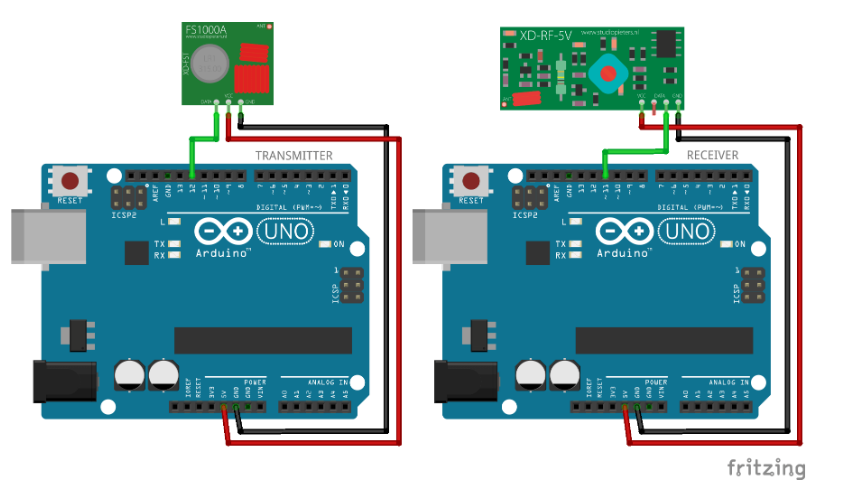
05/29/2024 at 23:15 • 0 commentsSo we're using the RF433MHz module with the VirtualWire arduino library to transmit and receive joystick coordinates to steer the robot in the desired direction.
We've followed the wiring diagram below:
![]()
-
Taking control of our robot: creating the joystick.
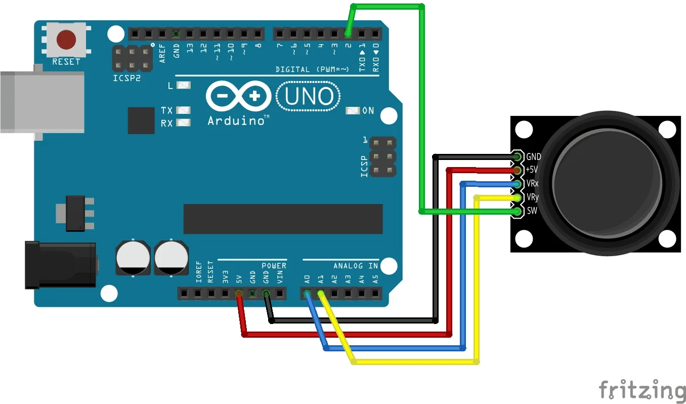
05/29/2024 at 22:53 • 0 commentsTo control our robot when it's in “manual” mode, we had to design a joystick to manage its movements. We started by connecting the joystick, following the instructions and wiring diagram below:
https://arduinogetstarted.com/tutorials/arduino-joystick?utm_content=cmp-true
![]()
We just didn't connect the SW pin (used to read the status of the joystick's built-in button), as we don't yet see any use for it in our project.
Next, we studied the different ways of communicating between several arduino boards in order to send the joystick coordinates to the board located in the robot. We opted for radio transmission and reception, which we felt was the most appropriate solution for our project.
-
The engine starts up: it's finally moving.
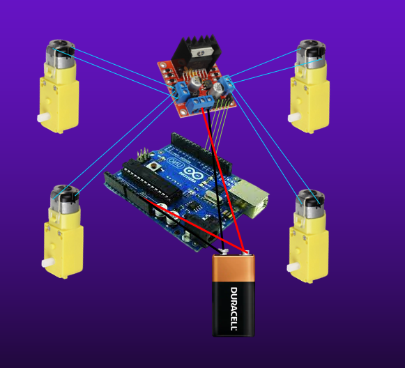
05/29/2024 at 22:40 • 0 commentsWith the structure ready, we put together the electronic assemblies and codes to set our robot in motion for the first time.
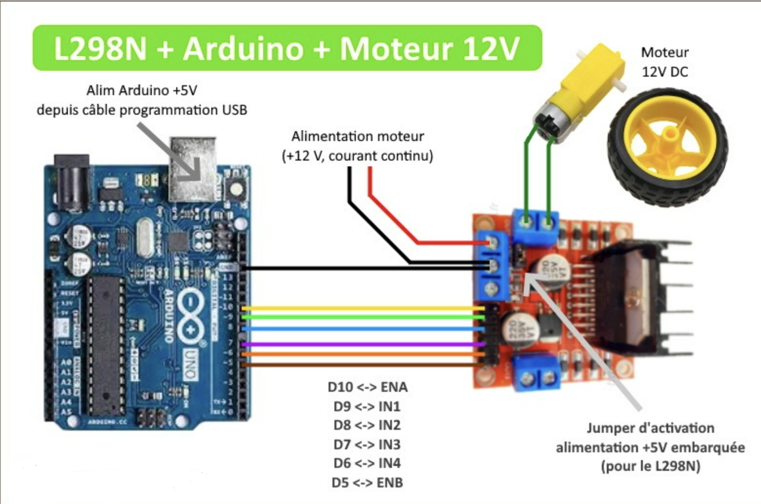
So we're using four DC3V 6V Dual Axis Gear motors, with the four respective plastic tyre wheels, and to control them we needed an H Bridge Motor Drive Tech, L298N Motor Driver.
To make the assembly, as well as the code, we looked at various datasheets and followed several tutorials such as:
https://www.st.com/en/motor-drivers/l298.htmlTutoriel L298N : fonctionnement, branchement, code arduino (passionelectronique.fr)
Finally, our robot managed to take its first steps with a simple “move forward” function coded for testing !
R2D2 & Mars Rover Robot
The ultimate robot with Arduino: a faithful replica that captures the magic of the movies, featuring both manual and automatic modes.