Close
0%
0%

Macintosh SAO

It's the 40th anniversary of the original Macintosh. Why not recapture the magic in an SAO?

Similar projects worth following
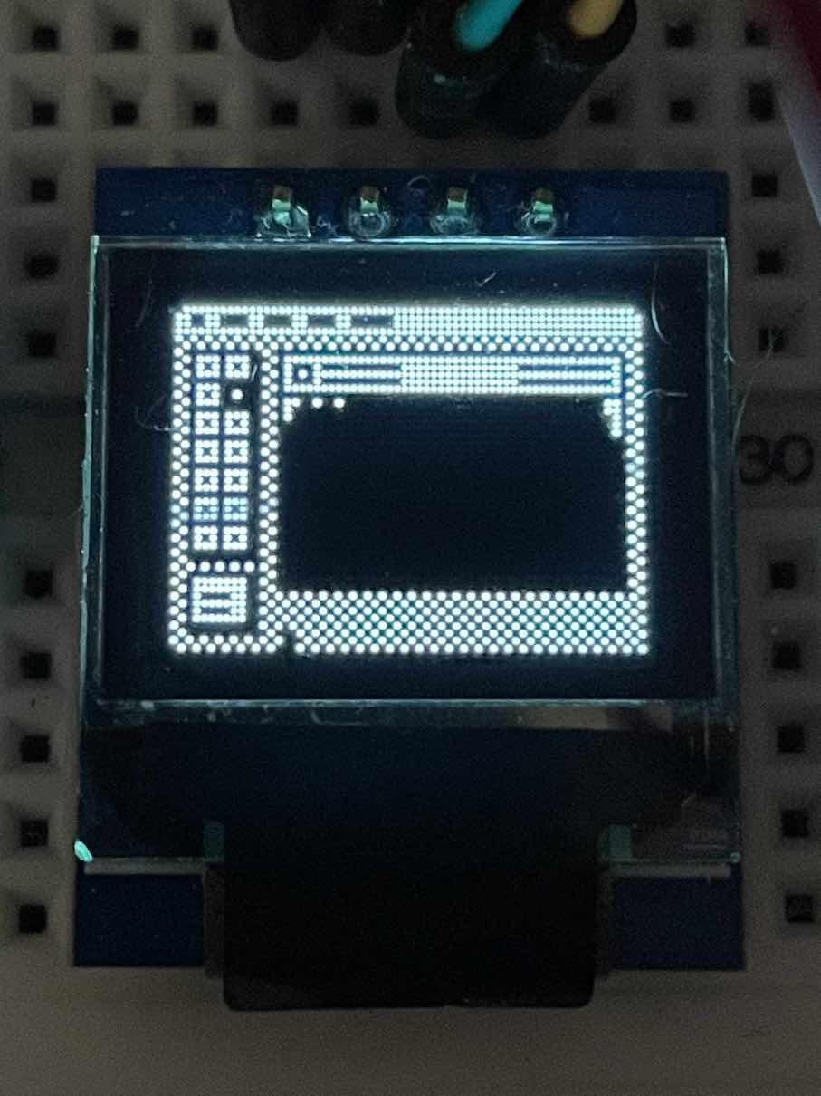
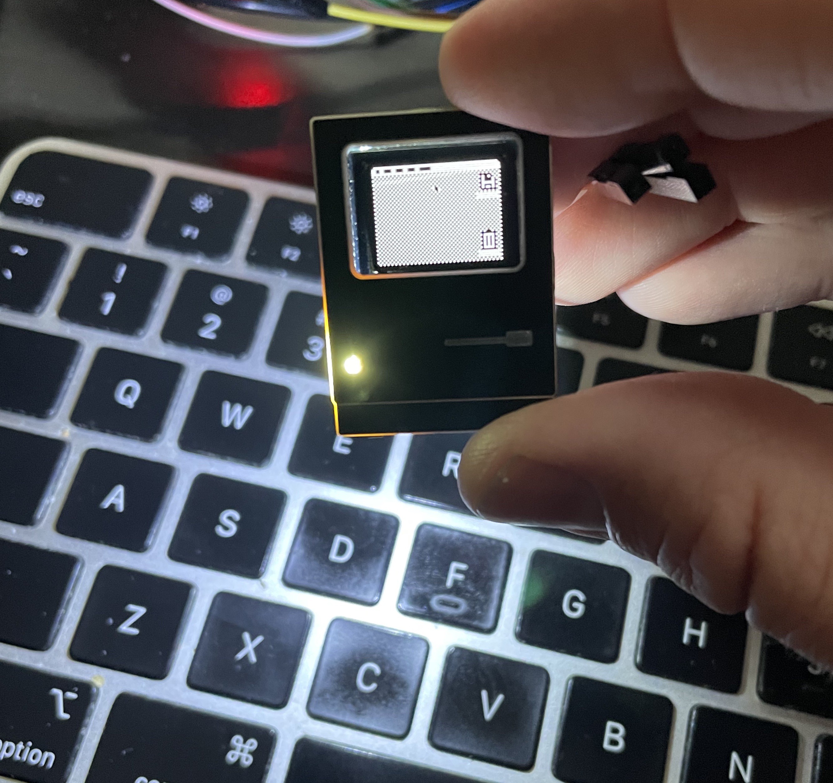
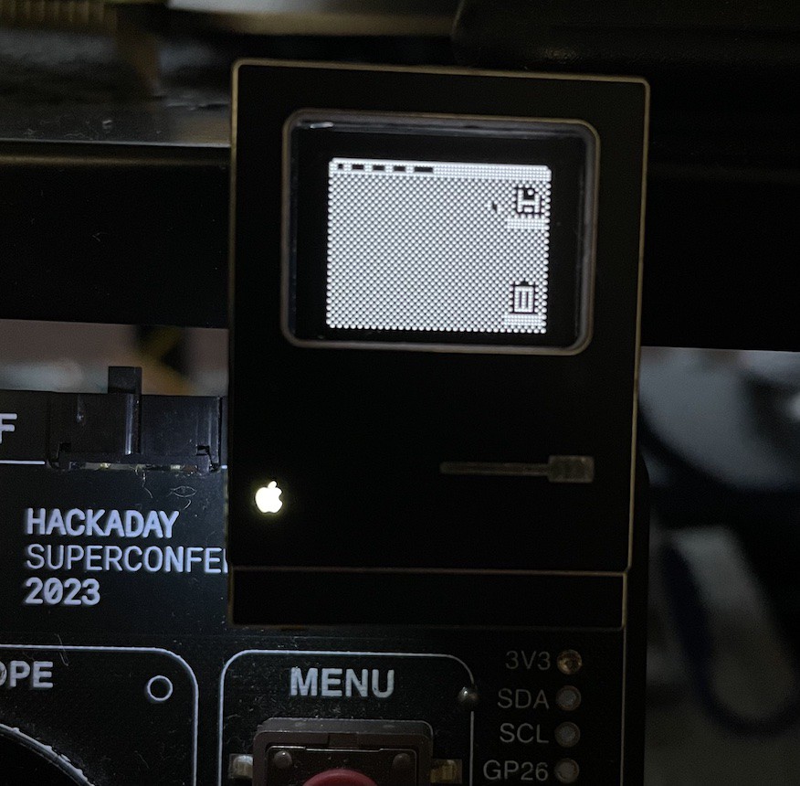
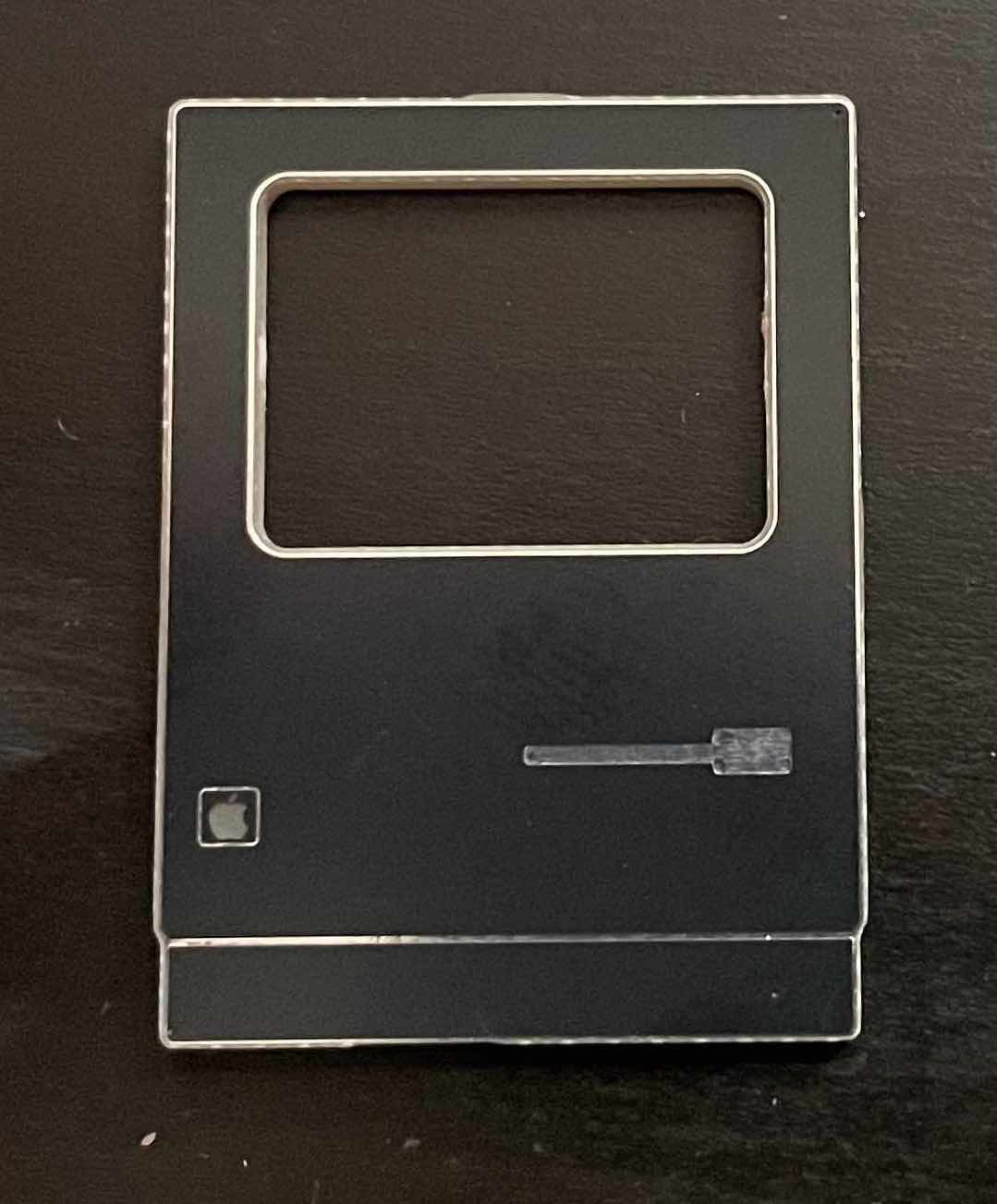
To celebrate the the 40th anniversary of the introduction of the original Macintosh, this SAO will... look like a Mac. And maybe act a little bit like one too.

Instructions on use and documentation will be available at aeiche.com/macsao.

This project uses the following components: 

  • CH32V003 J4M6 (the 8 pin SOIC)
  • An SSD1306 64x48 px OLED display (white)
  • A Fremont Micro FT24C64A EEPROM 8KB
  • A Side-shining LED 
  • A Panasonic EVQP7J01P right angle SMD button
  • A resistor for the LED
  • Two capacitors for noise reduction on power signal.

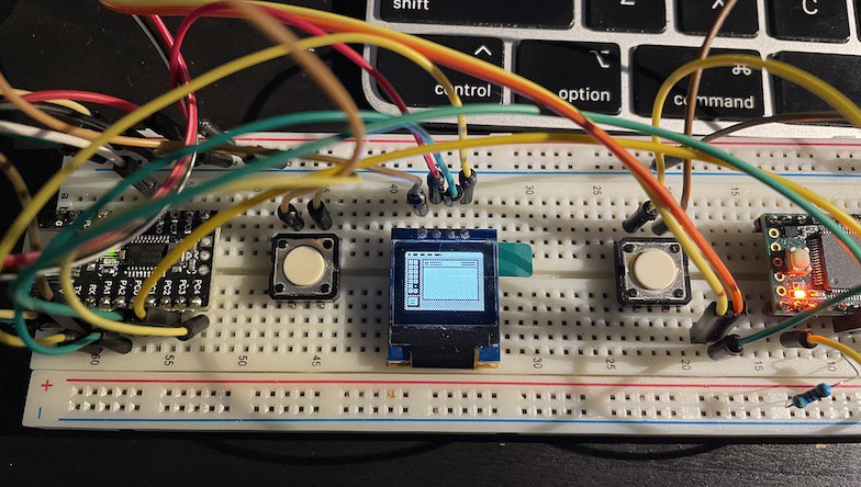
In addition to the I2C interface on the SAO, GPIO1 can be used to program the CH32V003 with the WCH SWD protocol. GPIO2 acts as a 2nd entry point for the button. So if you don't feel like pressing the button, you can use that pin.

How do I draw something on the screen?

The API is still a work in progress, but the short version is this: You send bytes to the SAO and those get interpreted as drawing commands. Here is an example of a command you could send: 

0x01  // Control byte 1 - write this to the display stack directly
0x01  // draw the desktop
0xFF //  END background
0x10  // Mouse to 
0x07 // x coordinate: 7
0x28 // y coordinate: 40
0x01  // again, draw the desktop
0xFF //  END background
0x10  // Mouse to 
0x37 // x coordinate: 55
0x1E // y coordinate: 30

This will draw the mouse going from (7,40) to (55,30). Once the animation is done, the mouse will go back to (7,40) because the whole thing starts over again. It'll repeat endlessly. These bytes are written in hexadecimal, but you're just sending numbers anyway, so keep in mind that when you write your code you can probably just use decimal.  Full documentation on the commands will be available soon. Among other things, I hope to provide a nice set of Mac-like stuff in the API as well as just simple drawing commands, if you just want to draw to the screen using a basic graphics library.

  • 1 × CH32V003 J4M6 (8-pin SOIC)
  • 1 × SSD1306 64x48 0.66" OLED display (white) 4 pin i2c variety.
  • 1 × Freemont Micro FT24C64A EEPROM (8K)
  • 1 × Panasonic EVQP7J01P Right Angle SMD button
  • 1 × 1K ohm Resistor (for LED)

View all 8 components

  • Oh no!

    Aaron10/30/2024 at 15:13 1 comment

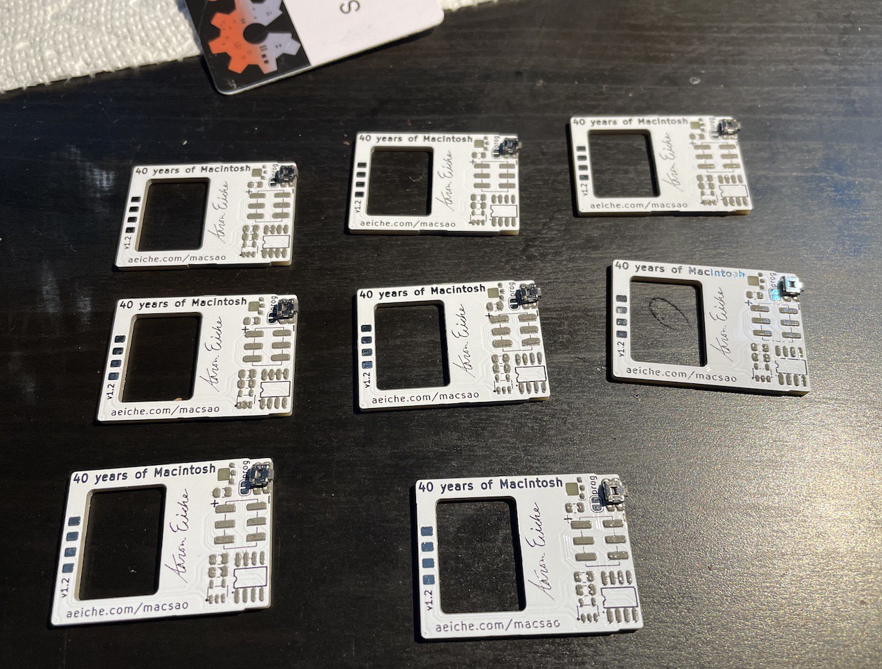
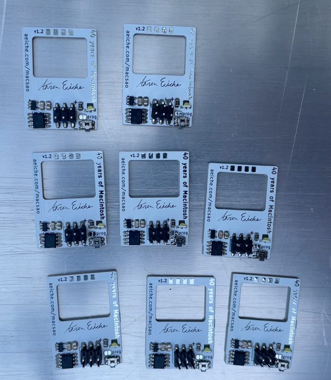
    This is far less of an "oh no" than it is an "Oh, rats". First, I had a production problem: I made 8 white MacSAOs, and cranked the toaster oven too high: I burned them. While I was hoping that it might give a kind of nice Beige color like the original Mac, they really just look like they were in the oven too long (which they were). Fortunately I had enough extra PCBs to make my goal (50) so I did another batch of the white. 

    Regular, and extra crispy

    The biggest limiting factor on how many I can make is the number of i2c displays. I only ordered 55 total, so I had a few to lose. After all is said and done, I expect to have 51 SAOs total.

    The second 'oh rats' came when I took a picture of the final product to post here, and I noticed that the detail line that breaks up the top of the Mac and the 'foot' somehow did not make it into the final product. 

    Left: New, no detail line. Right: has Detail line.

    It's purely aesthetic, and I didn't notice it until after working on it for 2 weeks. So I'm just kind of bummed about it.

    I've got 40 white MacSAOs made, and 2 Black (I'm making 9 more). 

    Supercon is just a couple of days away at this point, so we're in the final stretch!

  • Helpful tools

    Aaron10/18/2024 at 19:32 0 comments

    Now that the hardware is proven, and assembly has begun in earnest, I'm left with the list of todo items for the firmware to allow users to draw what they want to draw. 

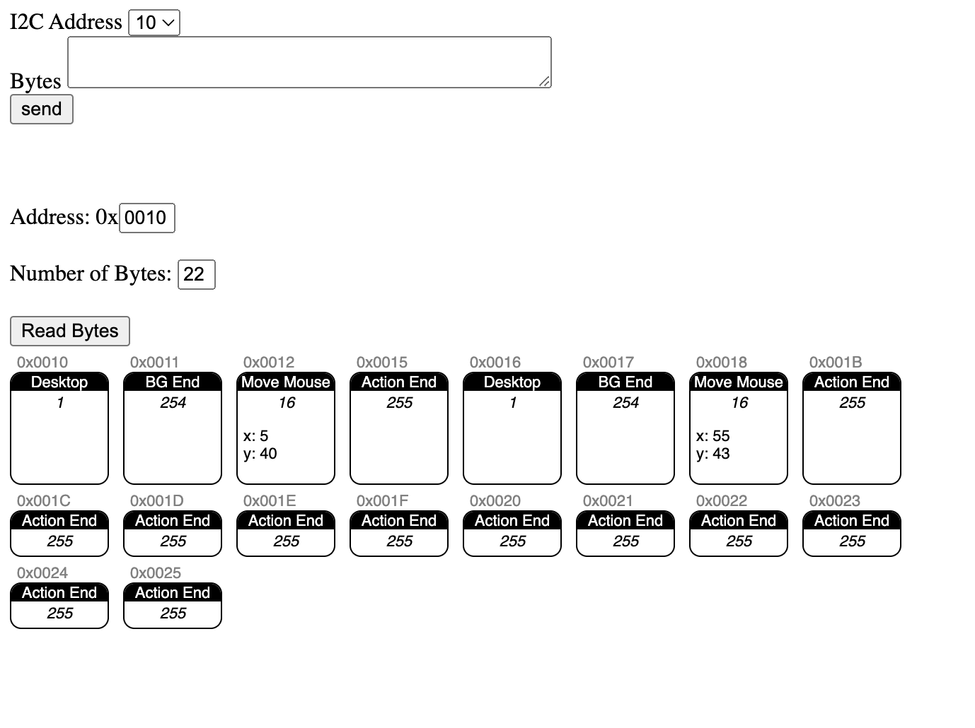
    The testing cycle for a number of these items can be kind of rough, and i've begun building tools to help things go smoother. A couple of weeks ago I started serving a webpage on a Raspberry Pi Pico that would take form data and send I2C commands to the Mac SAO. I have constantly hacked away at it and after adding an interpreter, it's allowing me to find where problems might be

    This is my helper app. The send feature is still relatively simple, but the read bytes feature will pull down the bytes from the SAO, and interpret them. Depending on the command, it may read additional bytes for arguments (such as the Move Mouse command taking an X and Y coordinate). It tracks the address for a given command so you can see what you're looking at.


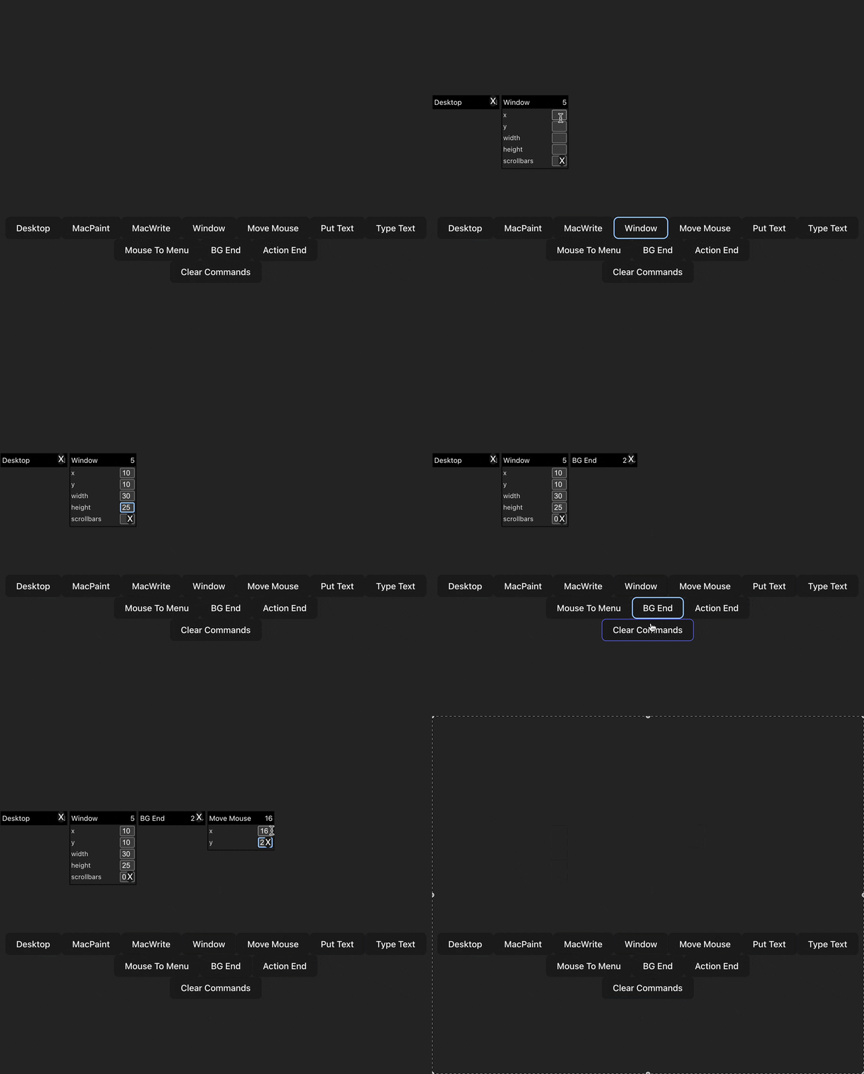
    My current plan is to have a version of this alongside the documentation - and hopefully with a command sequence builder. While some people would have fun reading through docs and figuring out how to assemble their own sequences, sometimes a helper tool gets you where you need to go.

    Here's an early version of a React-based app - which is programmatically far more complex but also a lot better at managing state than my handcrafted Javascript:

    My current functional version (which largely includes just fields for typing in bytes) is on a Pico W - making it convenient to write both the web app and the master i2c component in a single piece. Since we don't yet know what is onboard the Supercon 8 Badge, I've been giving thought to the most convenient approach.

    It turns out that Chromium-based browsers are capable of communicating over a Serial port. There's some permissions of course, but it's reasonable to assume that you could hookup to a browser, open the port, and then start sending messages. I had some misgivings about sending the bytes over UART and then translating them to i2c - but the web server version is already doing that. This is just a different comms mode. 

  • Production runs

    Aaron10/12/2024 at 01:18 0 comments

    I just did a test run of my  production process, pretty smooth!

    A few weeks ago the Hackaday.io Bits newsletter had a little blurb about this project and said “We can't decide if it looks better with white or black silkscreen!” That pushed me to include a few black boards in the PCB order alongside the white version. 

    My production setup includes a paste stencil jig, which is made up of a platform to mount the board, a space for the stencil, and some magnets to hold the stencil down. I may end up trying to make a hinge-based solution so it’s easier to lay-down and pick up the stencil, but for the time being this worked pretty decently.

    Paste-applied, placing the button

    My first solder paste test was done in a toaster oven. This time around I decided to use a hot plate (it allows me to film, and is easier to see the reflow.) Many years ago a friend and I put together this setup. He had gotten us copper plates to act as a heat spreader. I can’t find that plate, but I have this piece of sheet aluminum that did the job fine .

    Reflowing

    So far I have 8.5 white Macs, and 2 Black. The 0.5 was my hand-applied solder paste version where I didn't have enough paste on the pads for the button and it popped off. It'll go into the "fix it" pile.

    So far I'm very happy with how they're turning out. I haven't tested all of them because I haven't put together a programming setup more than the loose wires of the CH32 W Link. And the firmware is not yet finished.

    As a final note - you may have noticed I put my signature on the board. Eagle-eyed readers may notice that when fully assembled, its hidden behind the display. This is a reference back to the original Macintosh. As the machine neared production, Steve Jobs decided the Mac team should sign their work, as all great artists do. While I don't think of myself as a great artist, it's my homage to the signatures of the Mac team were debossed into the case of the first Macs.

  • Jiggery-Pokery!

    Aaron10/09/2024 at 23:34 0 comments

    My new boards arrived! After a bit of eval, I'm feeling very confident that they do what I want them to. Also, cutting the additional square out for the Apple logo looks very nice, and I'm pleased with how it turned out. 

    Most of the components on the board are SMC, so I'll squeegee some solder paste on, place the components and either bake in an old toaster oven or use the hotplate I got for the purpose. 

    The thing I can't do via reflow is solder on the display. As previously noted, I stumbled into the idea that I could just wick the pins onto the contact pads with a bit of solder, but aligning the display was going to be an issue.

    Of the many benefits to the home enthusiast 3D printing has bought, one of them is custom jigs. A simple tool custom made to help you accomplish positioning or accuracy. 

    I wasn't entirely sure how to put mine together. I needed to position the display, and the PCB, make room for the button which is at the bottom, and of course leave the top open so I could actually solder the thing. 

    I made a lot of jigs. I eventually settled onto a fold-over setup. The bar that sets the position rests on the placement of the SMD resistors 

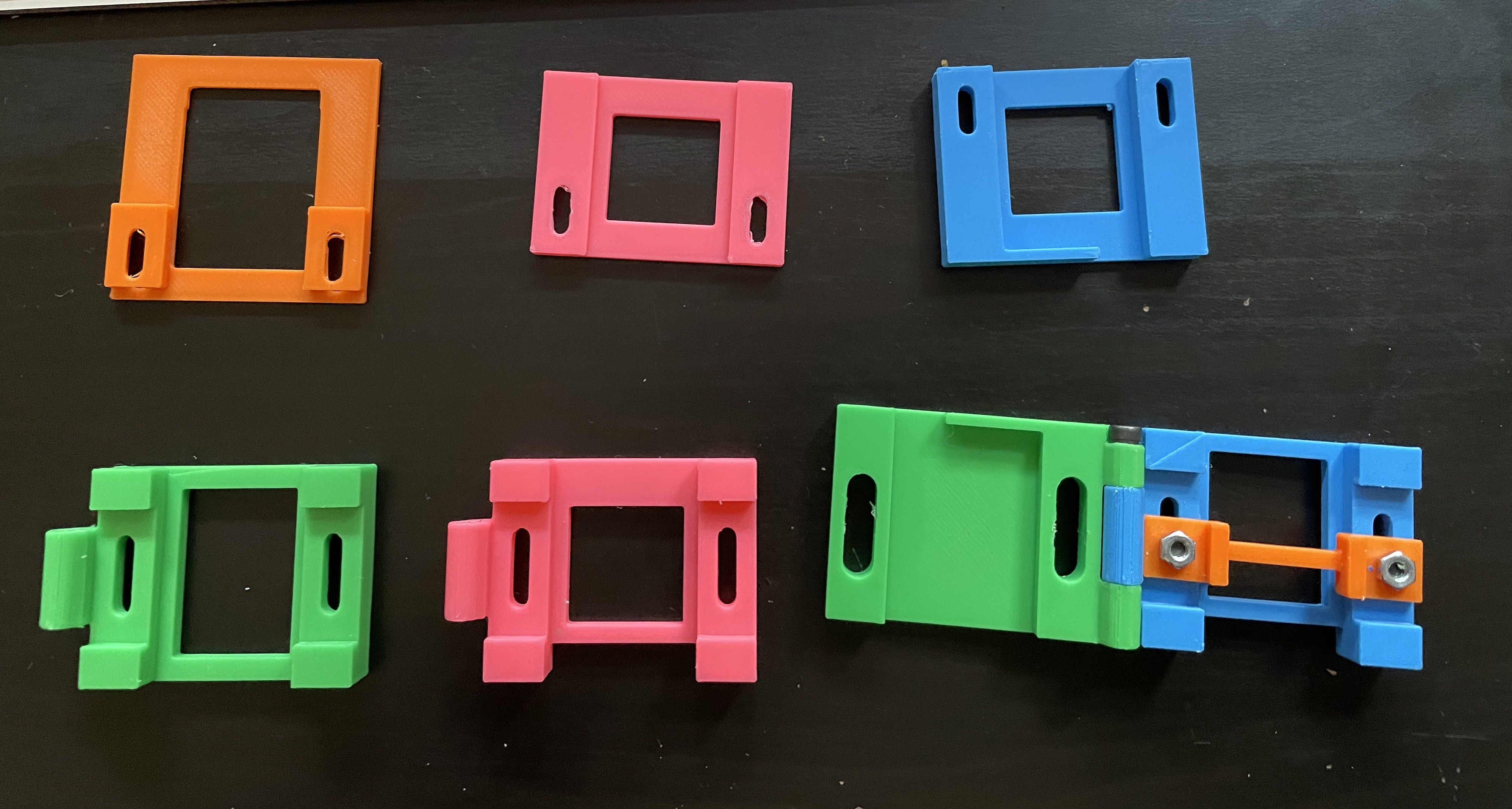
    Left to Right, my various attempts at a jig

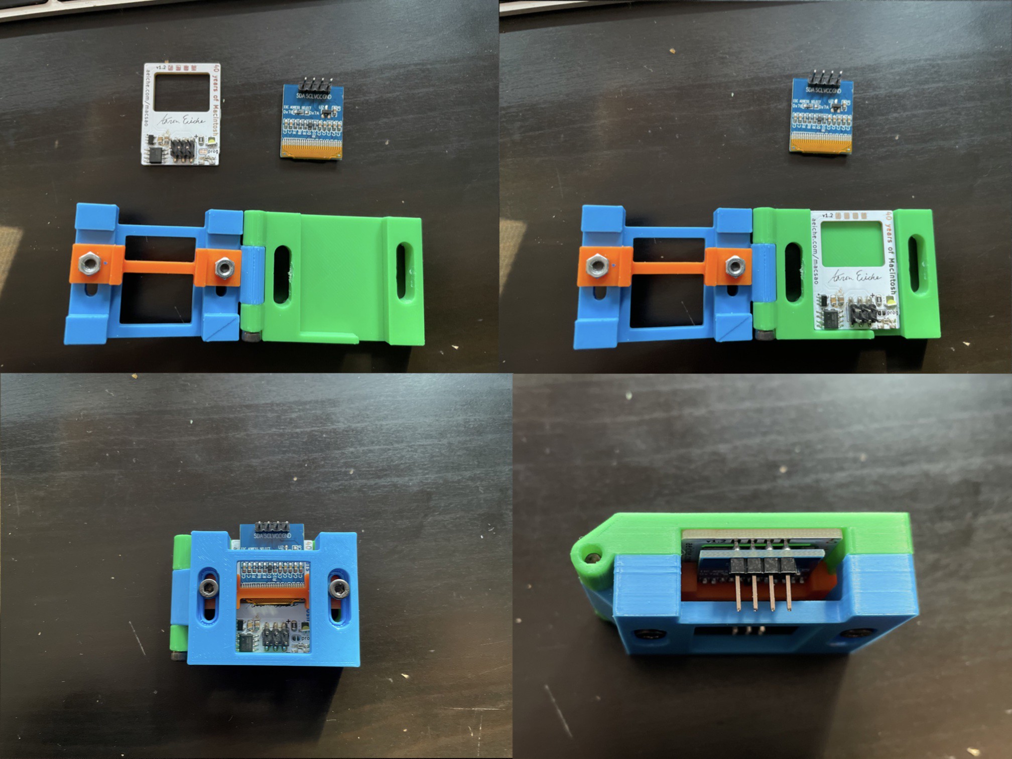
    Eventually I managed come up with a working design. The operation is pretty simple. Put in a reflowed board, close, slide in a display. Solder the pins. 

    The second display I've tried to place with this fit very snugly in the orange display-positioner. So I can also pre-place the display. I'm tempted to make one more run of the green base, cutting open the back so I can check the display from the front-side, but if I've tightened the screws right it should be repeatable.

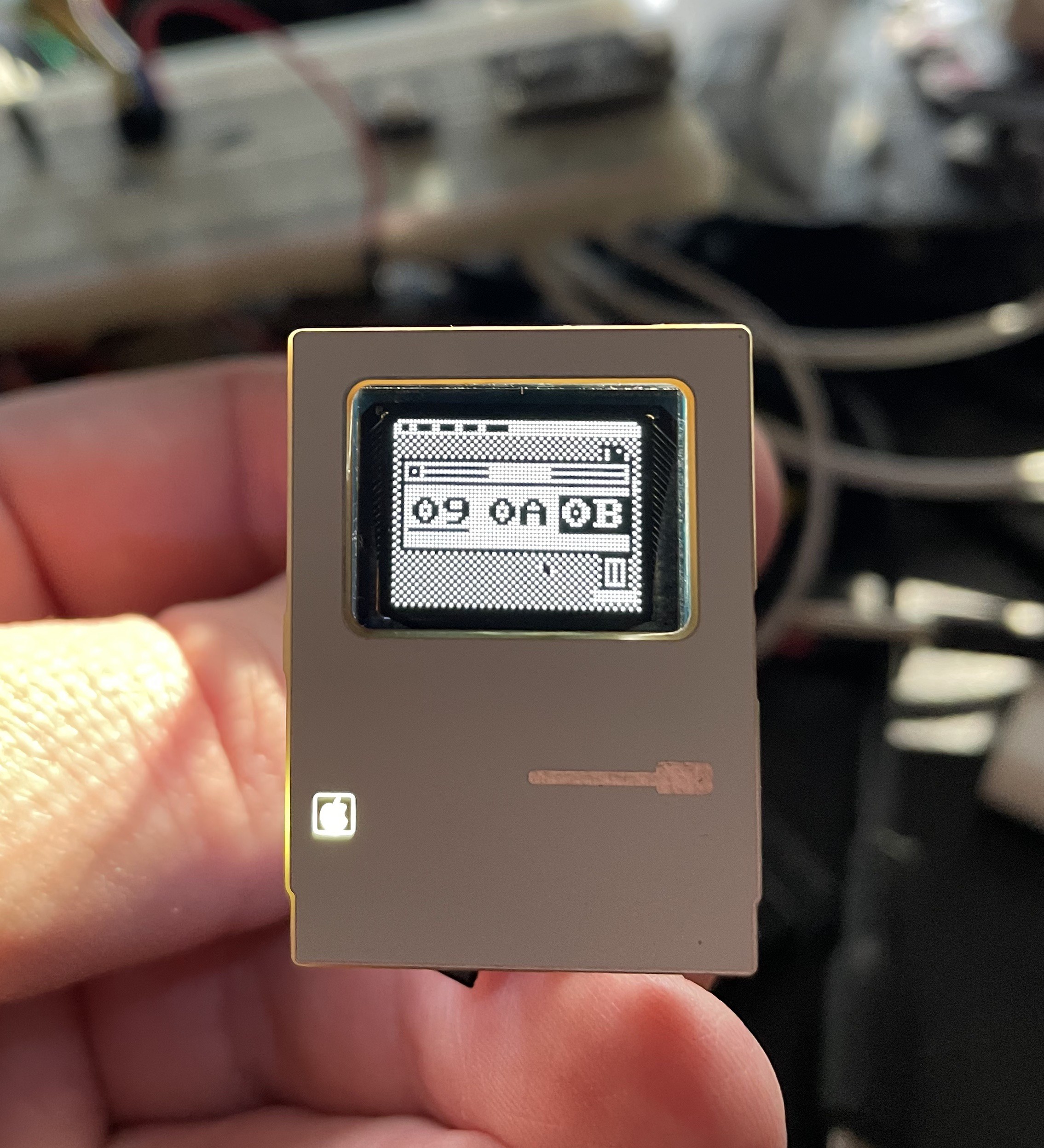
    And here is the first product: 

    The logo doesn't look as intense in person

    Gotta finish the firmware. Gotta complete the documentation.

    “Jiggery pokery!” said Harry in a fierce voice. “Hocus pocus — squiggly wiggly —” 

  • "Painting" in MacPaint

    Aaron10/05/2024 at 19:23 0 comments

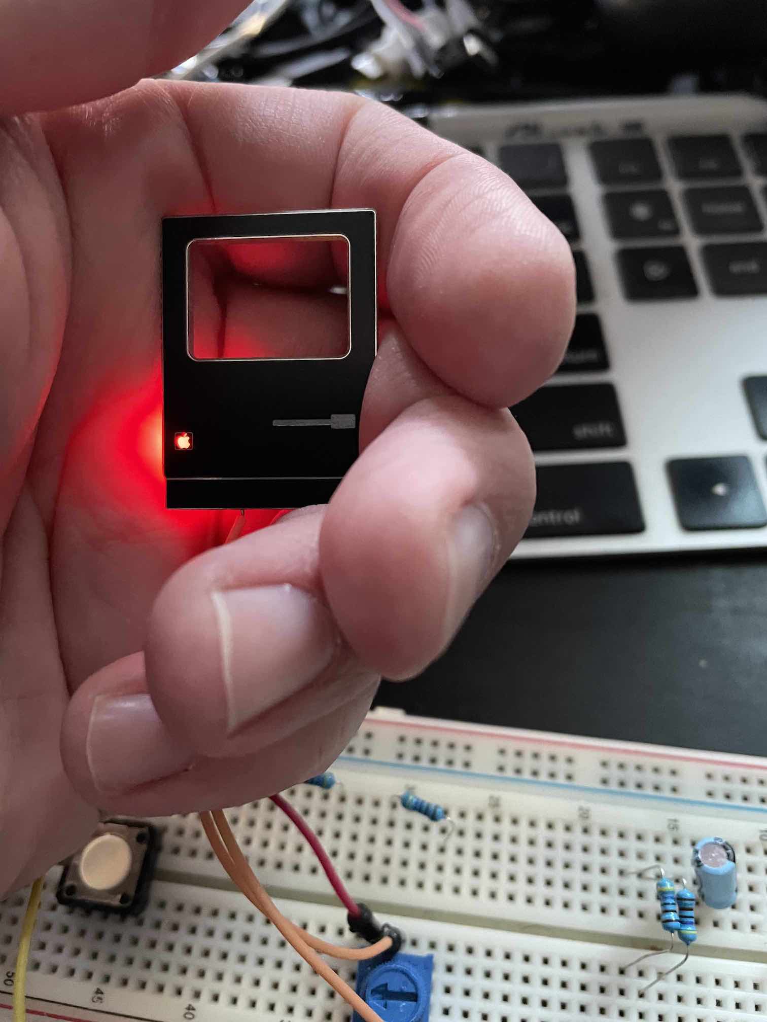
    While I wait for the final (fingers crossed) boards to arrive, I had to figure out the appropriate resistors for the LED. In addition to the white LED, I did a test of red and it turned out really nice - the picture here does not do it justice. I think I'll make a few with red, and the rest with white. Additionally, I'm contemplating getting some opaque black hot glue to act as a light baffle. I really don't like the way the light bounces out the back.

    I'm in the middle of reevaluating the command processor, because I'm testing the limits of its practicality and I want it to be as easy as possible for a user to make the thing they want to make. And do lots of different things with it. 

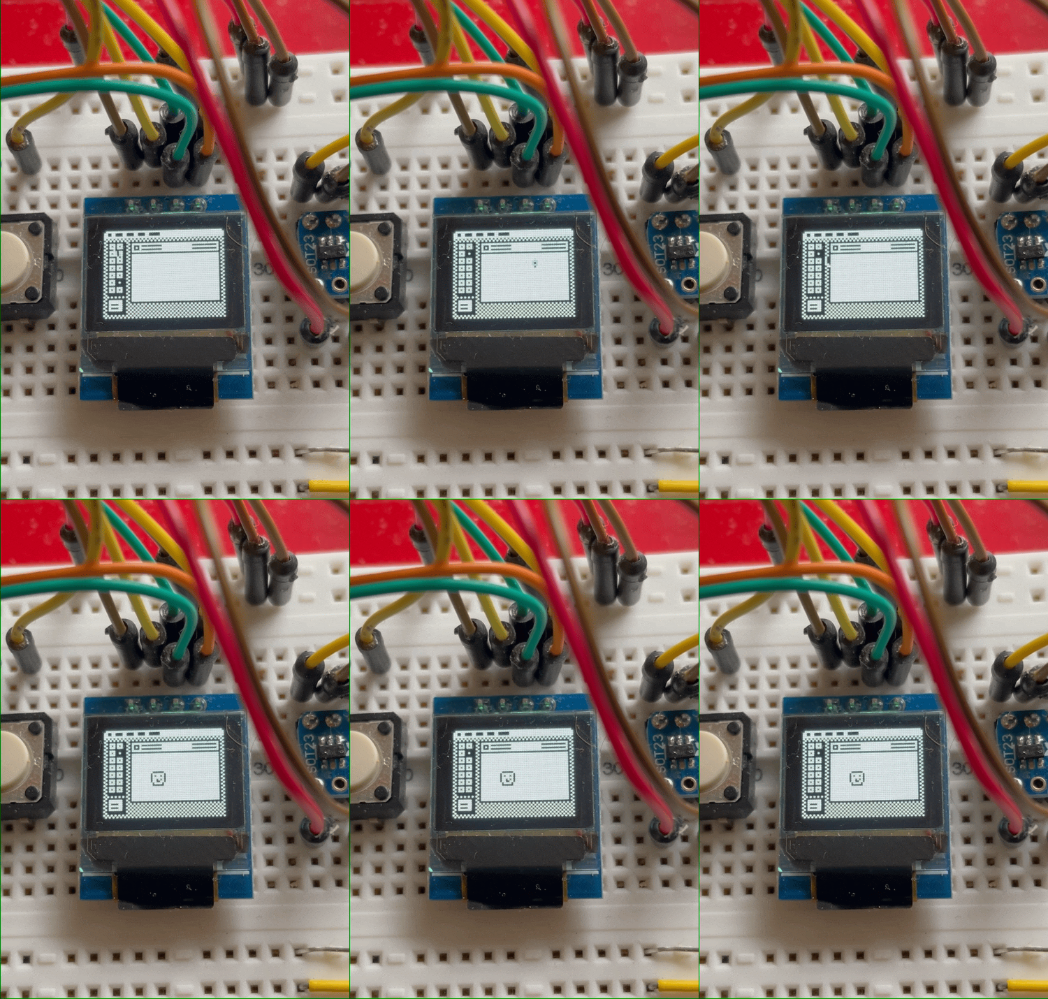
    Anyway, I've added a buffer to MacPaint so you can draw on it and it persists between drawing screens and animating the mouse and whatever on top of it. This is really exciting to me because its critical for one of the big showpieces I wanted for the MacSAO (I don't know if I'll reveal that here before Supercon)

    Figuring out the buffer

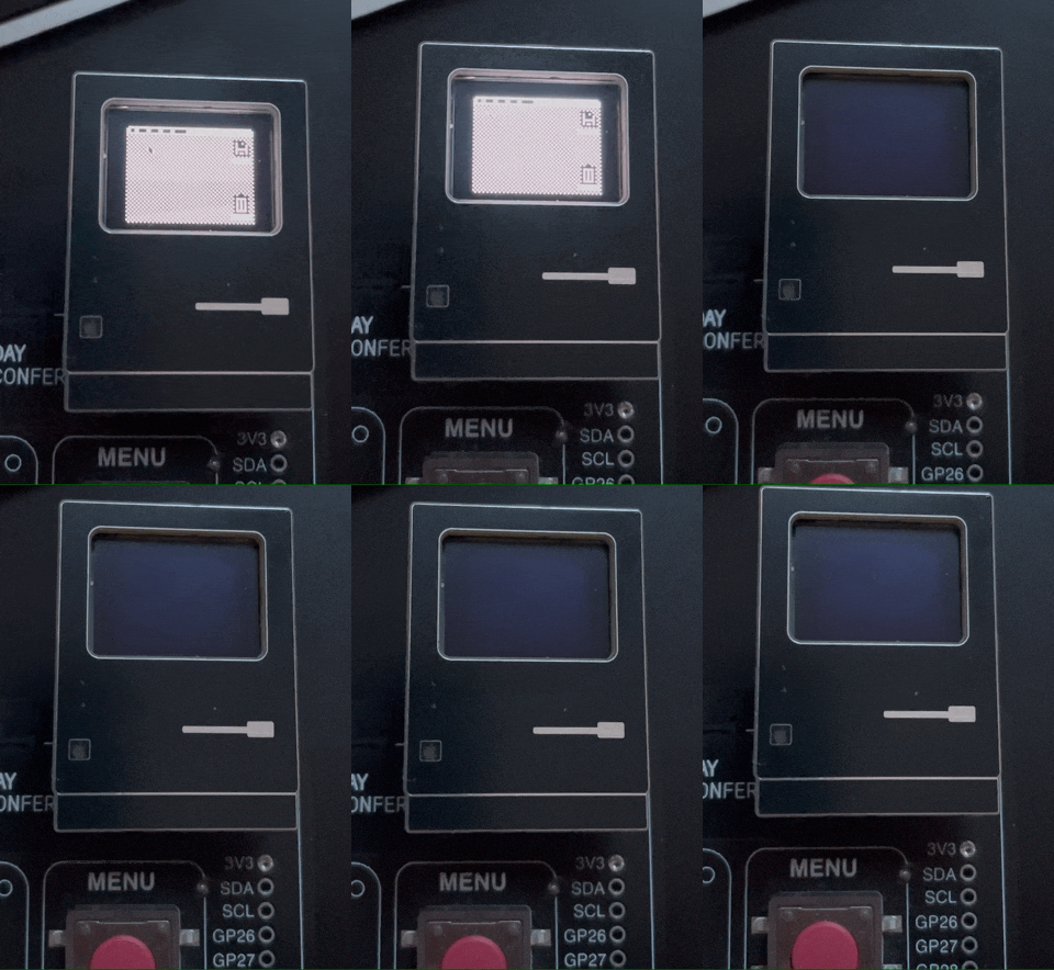
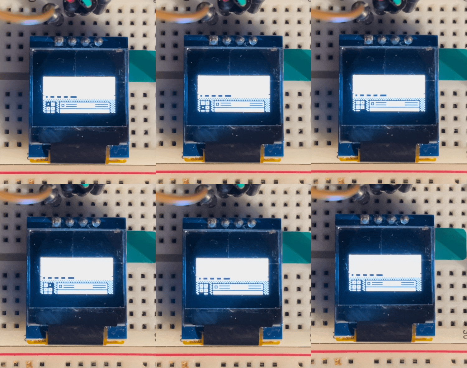
    The next big thing to tackle is the command structure. Right now before any action (like animating the mouse) you have to redraw the background. That makes sense, but the current system means you have to send a new command doing it again. So for instance in the gif below I have to explicitly draw the background before each step. I have a plan to handle this programmatically, but haven't gotten there yet. 

    The smile is a little lopsided due to bad coordinates

  • Characters and "Typing" in "MacWrite"

    Aaron09/29/2024 at 03:06 0 comments

    I've ordered the final boards for the Mac SAO and (provided I haven't made any catastrophic mistakes) I'm waiting for them to be manufactured and shipped. In the mean time, I'm tackling more firmware, and todays exploits were "typing out" characters in "MacWrite"

    The display on the MacSAO is only 64x48 pixels. The character font that is included with the CH32V003fun library are 8x8 pixels. Putting nothing but these on the screen will get you 8 characters per line, and only 6 rows top-to-bottom (with no spacing). 

    I started poking around for a font that would be sufficient. There are a few 4x3 fonts out there, but I didn't want to worry about licensing, and I did want to be able to distribute the source eventually. I found a great font in Romeo Van Snick's Creep, which is a 4px wide font.

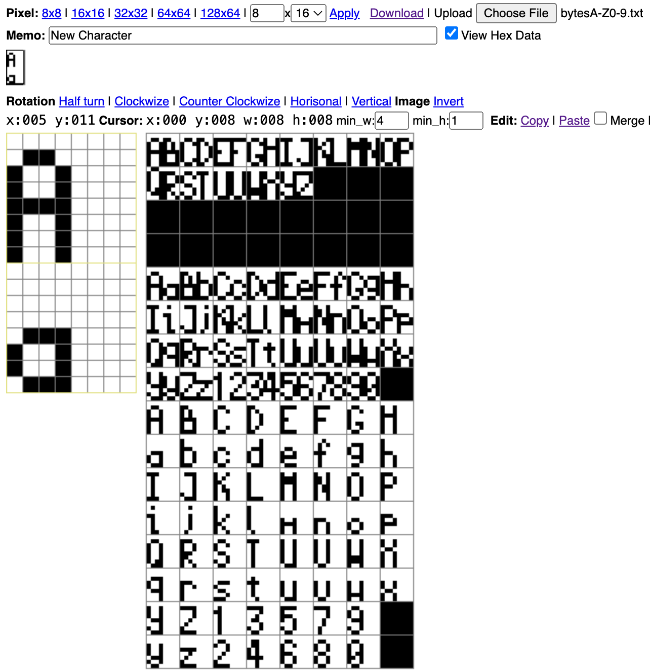
    I couldn't find any way to simply extract the bits from the font file, so I ended up reconstructing them in Emutyworks' Bitmap editor. While I was doing this, I ended up altering some of the characters more to my liking.

    As you can see from the bitmap, I tried a few different approaches. There is a world out there where I managed to get the combo Capital/Lowercase-in-a-single-byte to work, but in the name of getting things done, I just put each character in its own byte. If I start running into flash issues, I may try to solve this. As an aside, working on a project at this resolution and this size really emphasizes how much you can rely on the human brain to fill in the gaps of an experience. Some of these characters are only recognizable because you know what their much bigger, much better-defined representations are. The lower-case "m" and "w" are particularly suspect.

    One of the frustrating problems I had was getting the characters to display in the way I wanted them to. There is the way that you store the data, and the way that you read the data. I was frequently getting mirrored characters, or characters rotated 90 degrees. The right way to handle this would be to have a good understanding of how the bitmap interpreter moves through the data and build according to that. Instead, I just leaned heavily into Jasper Van Loenen's image2cpp and trial-and-error'd my way to success. 

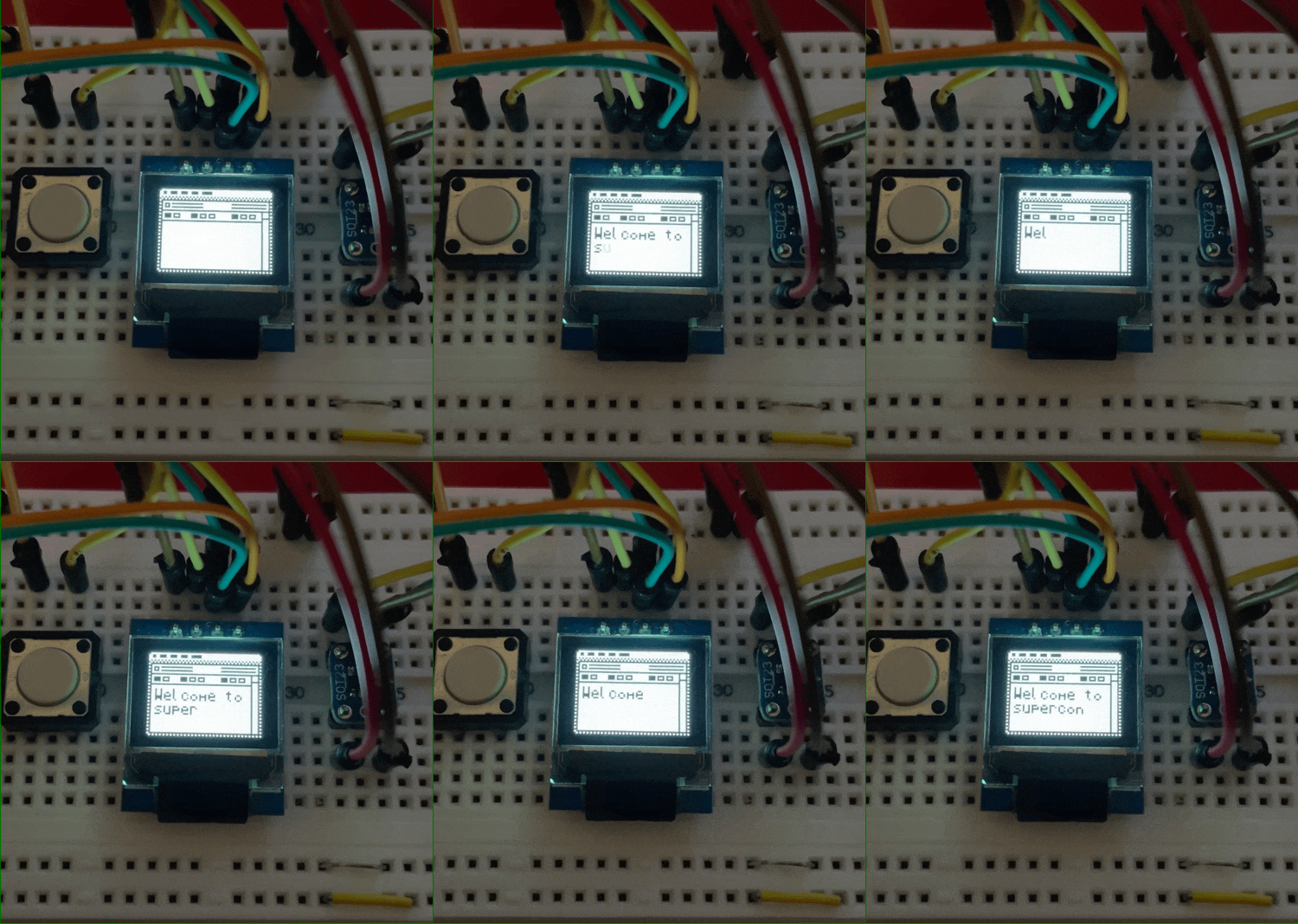
    With the characters taken care of, I started working on displaying the characters. I wrote an ASCII map to transform character codes into actual characters on the screen, and a method of animating them.

    I probably need to figure out a scrolling feature, but maybe I'll leave that up to individual users. 

    Glancing at my the statistics on the build, I am creeping up on the limits of the CH32V003. I have just 4k of flash left, and 196 bytes of ram to work with. I'm sure there are opportunities for creative efficiencies.

    I'm pleased with the result. I can fit 3 lines of text in the MacWrite window. There are 10 characters of space per line with a single pixel between characters. Some characters being narrower than others, you might be able to fit 11 or 12.

    At any rate, I'm having fun and I'm very pleased with how it's looking.

  • Memory and Light

    Aaron09/18/2024 at 03:37 0 comments

    I got in the EEPROM and the LEDs for the apple logo, and hand soldered them in place. The pads are not intended for hand soldering - that said, I managed to make it work.

    Perfect!

    This is the LED at 3.3V with a 0 ohm resistor. It is shockingly bright. If someone needs a flashlight this will serve very well. Suffice to say that I need to figure out a more appropriate resistor. Through a happy accident, I found what I think is the right brightness level.

    I plugged the board into my Vectorscope - which happened to have low batteries - and the LED brightness was just about right. I just have to measure the voltage, and do the reverse calculation to get the proper resistor value.

    Even with the brightness toned down, it presents another problem. If you look up at that first picture, there's a lot of light bleed out the left side of the Mac. The LED is putting light through the PCB, and the translucent fiberglass center of the PCB acts as a light-pipe.  The fix for that was simple, if a little hacky. I took a black sharpie and ran it over the edge where the light was bleeding.  

    When I get these boards made in white, I'm not sure the same solution will work as well. With the black soldermask, it's not really noticeable. With the white soldermask, even though its on the side, it'll kind of stick out. One wild (and expensive) solution would be to edge plate the board, so that there's a metal edge around the outside. It'd be pretty, but is only available in gold (ENIG) and I prefer the look of Lead-free HASL.

    EEPROM Woes

    I have run into another issue as I've been writing firmware. The EEPROM was not reliably writing or reading data. It would work 1 or 2 times out of 5. At first, I thought it might be too much resistance on the I2C lines. I removed the pull up resistors on the lines and of course realized that they're in parallel. If anything, they were lowering the resistance on the line. I thought it could be a timing issue - but no dice on that front either. 

    While thinking about how I2C works, it occurred to me that maybe my EEPROM calls were getting muddied by calls being sent to the display. I2C doesn't do anything to prevent the master from interrupting itself. And neither was I. Calls to the display are fired every loop, and the signals coming from outside the SAO can happen at any time. Since I2C data is relatively slow compared to the rest of the work the SAO was doing, it's a reasonable assumption I was tripping over my own shoelaces, so to speak.

    I added an I2C 'reset' to the start of my EEPROM handler, and everything has smoothed out.

    Finally, I found the point where my SAO stops working:

    2.58V. It sure does try though.

  • v1.1 Assembly test drive

    Aaron09/14/2024 at 02:12 0 comments

    My second test run (version 1.1) showed up in the mail today. Version 1.1 fixes and moves the SAO connector to the center, adds an EEPROM and an LED behind the Apple logo (thanks for the idea Tom!). The EEPROM and LED are still coming in the mail. 

    Protoype in Black, just for fun

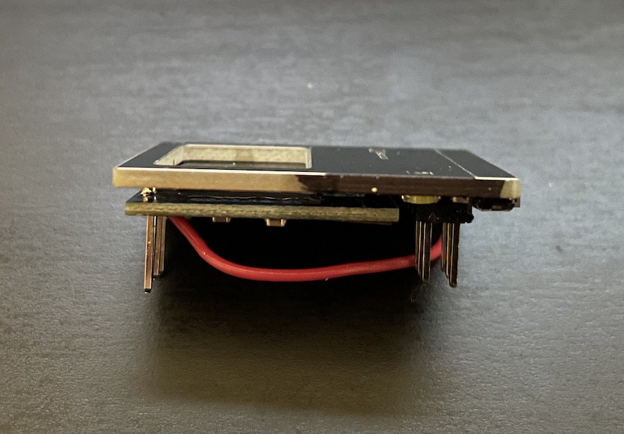
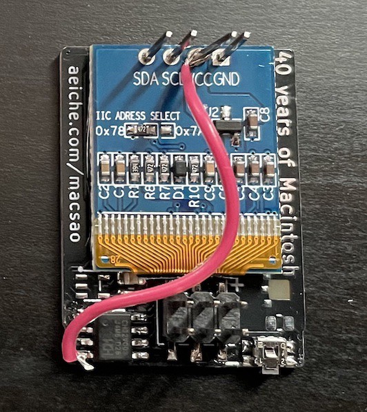
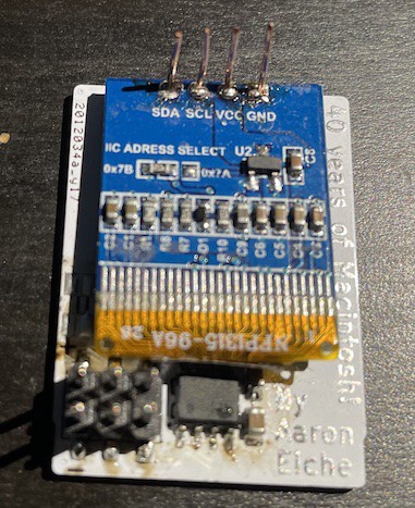
    One of the challenges I'm facing is how to attach the display to the main board. Because real-estate on the board is so tight, a typical surface mount header wouldn't work. I didn't want a through-hole header because I wanted the front of the SAO smooth. 

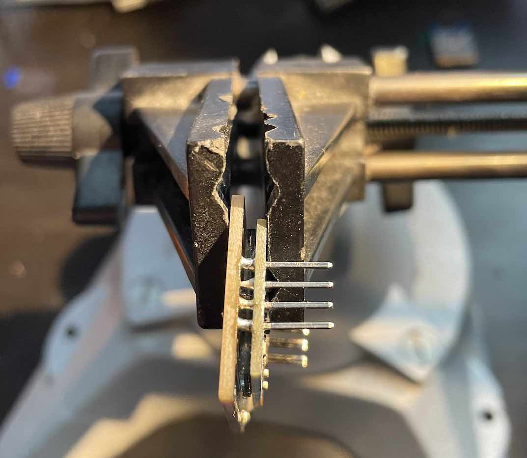
    The weird solution I'd come up with was to cut short lengths of copper wire and solder them to the pads on the back. It required desoldering the headers already on the board (and clearing the holes), sliding through the copper wire, bending them to the right position, and soldering in place. 

    I tried this a couple of times and in both cases, I accidentally ripped a pad off while bending the wire. This wasn't looking good. I have a few more test boards, and some extra displays to experiment with, but I didn't want to start losing parts to a hare-brained scheme. 

    Looking at the displays I'd bought - which again, had headers soldered in place already - I wondered if I could get away with just soldering the pins to the pads and just letting the surface tension wick the solder across the gap. As it turns out that solution worked really well, and is far easier to do.

    I proved the concept using the board I'd already damaged

    It's a tight spot to solder in, but the included tip of my PINEcil did it without issue The solder pad and pins do the real work. When I actually get to assembling en masse, I think I'll design a 3D-printed jig to properly position the display and the board relative to each other.

    Of course, given the pad I ripped away, I had to hack together a solution. Fortunately the contacts were easy to reach. When the EEPROM and LED show up, It'll take a little effort to get them soldered in place.

    I'm pleased to say that my software uploaded without issue on the first try. It even runs on last year's VectorScope badge. I was a bit surprised at this because I put rechargeable batteries in which are nominally 1.2v. The datasheet of the CH32V003 said that it wanted a 2.7v minimum. My multimeter tells me that the battery output of the SAO port is currently at 2.65v (that's freshly charged.) I'll have to see how long it can operate at that.

    There has been a bit of scuttle on the Hackaday discord about the startup state of this year's badge GPIOs. If you have the pin plugged into the SAO header, it may trigger programming mode. (Specifically, it was Tom Nardi's Cyberdeck SAO with the ATTiny3224, but I believe the CH32V003 basically uses the same protocol.)

    I have a board version in KiCad right now that adds a jumper for enabling programming via the header. With that, instead of bridging it with solder I would add a pogo pin to my programming setup and just have it connected which inserted. 

    I'm this close to being locked in on the hardware. Firmware is coming along. I'm working on the EEPROM storing and retrieving sequences.

  • Inside Macintosh

    Aaron09/04/2024 at 00:27 0 comments

    As near as I can tell, SAOs have largely been "flair". Something to stick on your badge to give it a little more personality. 

    Originally this project was going to be just that. A little display for me to do some fun things on. Once the focus on SAOs was announced for Supercon this year, my plans started expanding. Instead of just drawing some pictures on the screen, I decided that I wanted an API that anyone could use to draw on the screen. 

    After a week or so of hacking away at it, I have the beginnings of an API. A few "screens" and moving the mouse. The API is great because not only can other people who have it draw Macintosh stuff to the screen, but it makes all the things that I wanted to draw a lot easier as well. 

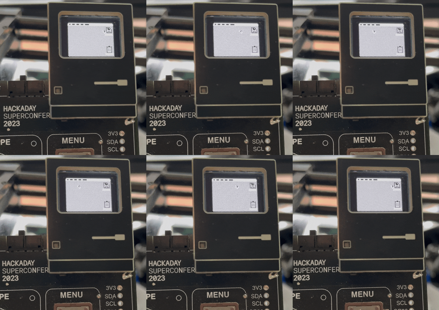
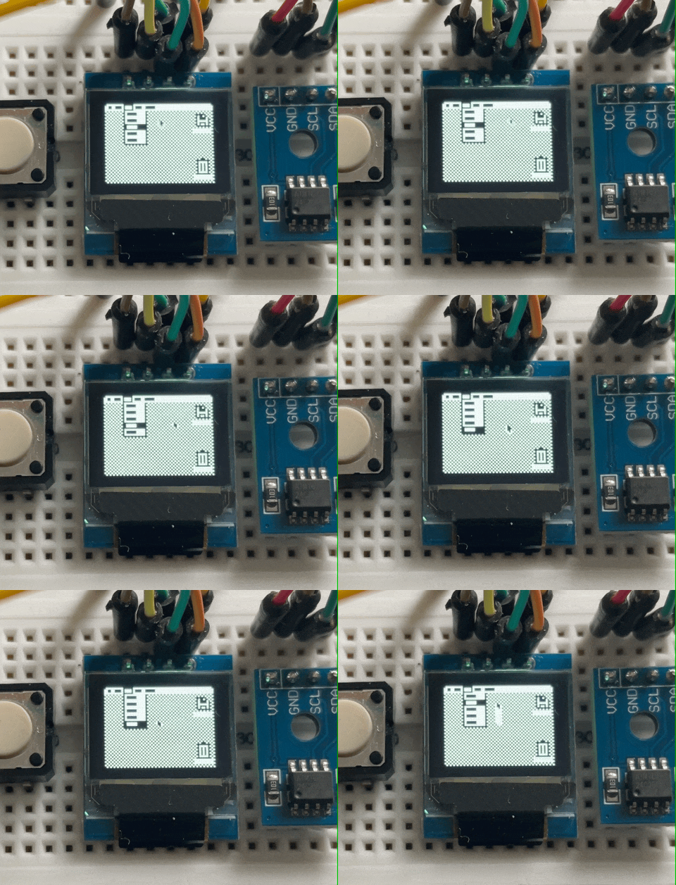
    The above animation is just a test of what I was working with - namely showing different selected menus and moving the mouse around. Previously I would have written a function that would draw these things. That's still true, but now with a layer of abstraction. I just send a series of bytes to the SAO and it stores and decodes them. The animation here exposes a bit of the stage magic though - the mouse and the menu aren't actually interacting.

    The API feels obvious to me now, but it was a while before I had a clear picture of how it would work. I settled on a structure that alternated between the background and the "animation" layer.


    The user could send a series of bytes to draw the background, and then an animation command that would draw the mouse moving around. The bytes are commands and arguments for those commands. They look a bit like this: 

    0x01 0xFF 0x10 0x0A 0x14 0x01 0xFF 0x10 0x1E 0x14
    
    // A break down of the commands: 
    
    // 0x01    0xFF 0x10    0x0A 0x14 0x01    0xFF 0x10    0x1E 0x14 
    // Desktop STOP MouseTo 10   20   Desktop STOP MouseTo 30   20

     The Desktop command draws the desktop. The STOP says "stop drawing background". MouseTo will animate the mouse from its current position to the coordinates provided, in this case (10,20). Once the mouse reaches (10,20), we move onto the next pair. We basically do the same thing but draw to (30,20). Once the whole set is completed, it loops back to the beginning. One of the neat things about this that the mouse doesn't care about where its coming from - So this would make the mouse move up and down and back again.

    As I've developed it, I've stumbled into amusing situations like the following, where I accidentally "paint" on the desktop with the mouse cursor: 

    Closer to Supercon I'll start working on documentation for how to write custom display animation. I still have a few firmware things to square (namely button interaction, and the i2c Address selection) before I can focus solely on the "Mac" parts of the project. And I still need to order new PCBs.

    Overall, I'm really excited about how it's all coming together. A couple of months ago this was a very different project, and I'm thrilled at how its turned out. 

    Inside Macintosh is the name of the developer documentation written by Caroline Rose that was provided for 3rd party developers when the Macintosh was introduced. 

  • From plus to minus, and from minus to plus!

    Aaron08/26/2024 at 06:14 0 comments

    I was a bit of a ways into working on this project when the announcement for this year's Supercon dropped, and the encouragement to bring your own SAO. As mentioned previously, I've become interested in both driving the display via i2c and receiving commands from the badge its connected to... via i2c.

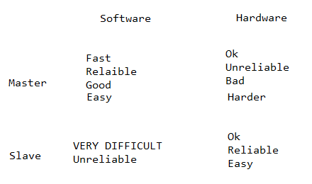
    Initially, I was sure the right way to do it would be to have the hardware i2c stack drive the display and the software stack to act as the i2c target for the badge. This appears to be exactly the wrong approach. Knowing far more about i2c than I do, Charles Lohr offered this helpful chart: 

    In short, when at all possible you should use software for the master and hardware for the target (slave) device. 

    Fortunately, that meant I didn't need to do a lot of work. I could use the CH32V003Fun implementation of hardware i2c to interact as a target, and a software library to serve as the master to drive the display. 


    After a few days of hacking around with it I managed to draw data to the display, but it was offset by a couple of pages (8 vertical bits per page) 

    This was odd because the hardware i2c version of the code that I'd written didn't show this problem, and the display setup was identical. Eventually I found that the software setup I'd replicated was designed for displays that were either 64 or 32 pixels tall. Mine is 48, and I needed to adjust the screen multiplexor to wrap at the right width for the right number of lines.

    The rest of the weekend I hacked together a proof of concept for running both i2c channels and it's working! 

    The prototype and a Teensy for testing

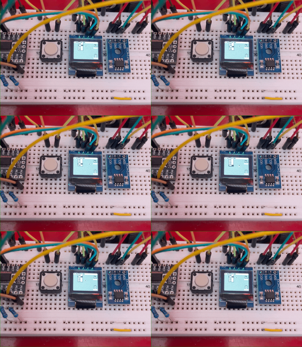
    This version is the display running off the CH32v003 on the left (Software I2C) and a Teensy 3.2 (on the right) is sending a packet (CHV32003 Hardware I2C as Target) to draw which tool is highlighted in this MacPaint window. It's an early test, but the proof of concept works. I have already rerouted the signals on the board.

    Lastly, the displays arrived. To my chagrin, they already have headers in them. This means that I'll need to desolder the existing headers and setup new ones. Because of my preference for a surface-mount connection, I also have to add my own headers to the board.

    I bought some AWG24 copper jeweler wire at a local craft store. Then I make a little bed, and hand solder. I haven't come up with a better process yet... 

    Hand-Crafted in the Pacific Northwest

    Next steps: 

    • Make sure Button interrupt works
    • Protocol for sending commands
    • New PCB spin

View all 20 project logs

Enjoy this project?

Share

Discussions

jeremy.geppert wrote 09/23/2024 at 01:43 point

Love the trick to hide the OLED pins!!! Brilliant! Mine are in the middle of the board unfortunately. There might be some liberal application of thick black automotive touch up paint to "hide" them. I hope you have the sad face mac screen on there at some point. :(

  Are you sure? yes | no

Andy Geppert wrote 09/04/2024 at 13:01 point

THIS IS AWESOME!!! Can't wait to see these in person!

  Are you sure? yes | no

Aaron wrote 09/05/2024 at 04:37 point
Thanks! I'm really looking forward to sharing it! I'll keep an eye out for you.

  Are you sure? yes | no

Gravis wrote 08/08/2024 at 13:07 point

What is an SAO?

  Are you sure? yes | no

Aaron wrote 08/08/2024 at 16:03 point

It's a circuit board you can plug into conference badges. They're often artwork made with different layers of the PCB. Sometimes they have LEDs or other electronics that make them interesting. It's pretty broad what they are.

Here are a few of links:

https://hackaday.com/2018/06/21/this-is-the-year-conference-badges-get-their-own-badges/
https://hackaday.com/2019/03/20/introducing-the-shitty-add-on-v1-69bis-standard/
https://hackaday.com/tag/shitty-add-on/

  Are you sure? yes | no

Tom Nardi wrote 07/05/2024 at 16:54 point

Love this idea. I've actually been thinking of spinning up a new run of the Cyberdeck SAO using the CH32V003, partially because I wanted to get some practical experience with it, but also because the ATtiny I used are ~80 cents a pop.

  Are you sure? yes | no

Aaron wrote 07/05/2024 at 22:55 point

Thanks Tom! I'm pretty happy with the 003 now that I've got my feet under me. Charles Lohr's libraries make it a lot easier. I look forward to seeing the next version :)

  Are you sure? yes | no

Similar Projects

Does this project spark your interest?

Become a member to follow this project and never miss any updates