Ayu
Ayu-
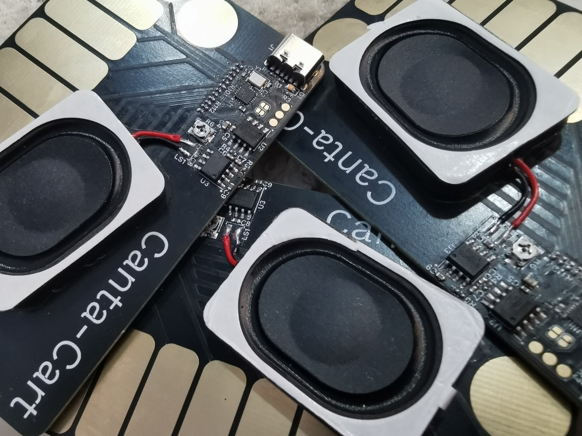
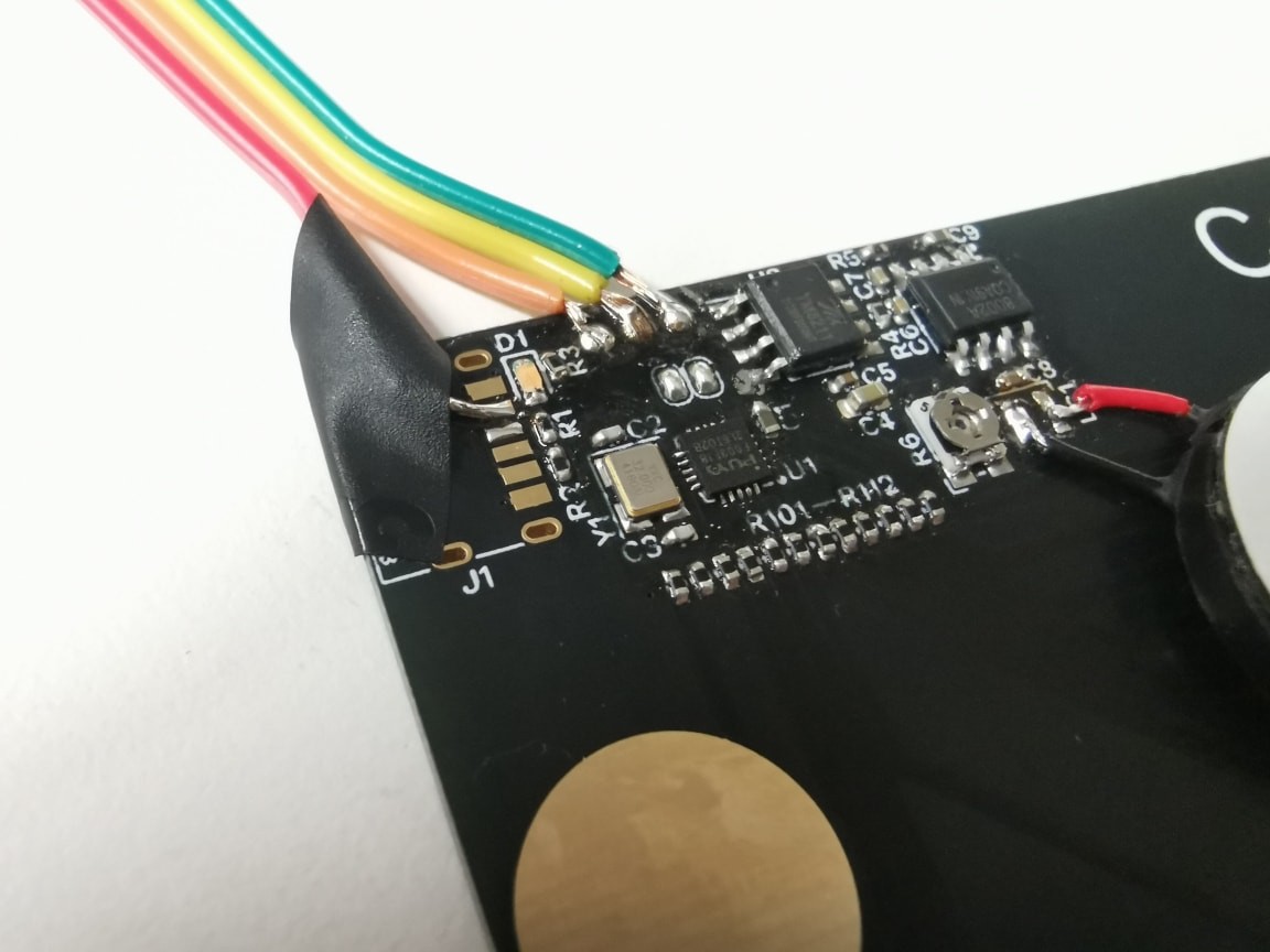
Speaker soldered
08/22/2025 at 13:09 • 0 commentsI finally allocated the time to solder this on. The enameled wire I've purchased was too thin, so I reached for the leftover clipped leads from through-hole LEDs.
 the speaker with wires soldered on; (2) the speaker soldered to the board.")
It takes some tweaking to get the length and angle right, but it is cakewalk overall (especially with a newly replaced iron tip ^ ^).

The speaker's single side of connection did not feel secure enough; it seemed that the soldering pads might get pulled off anytime soon. I finally resorted to electrical tape again, but I don't think this is the best way. I need some inspiration >_<
-
Canta CC
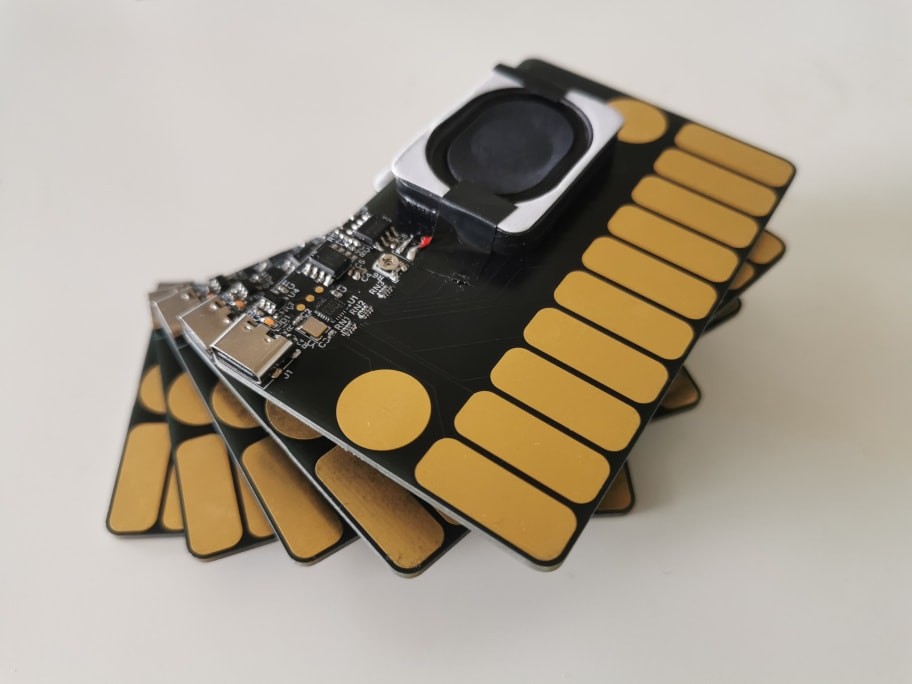
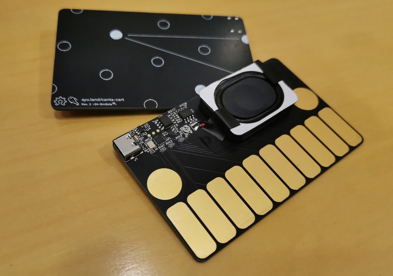
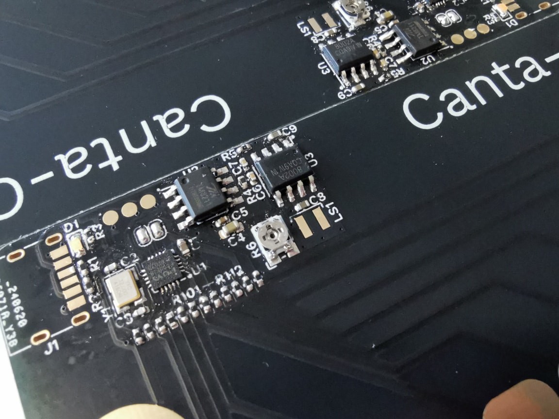
08/08/2025 at 14:53 • 0 commentsLet me introduce you to the new revision — Canta CC!

Among friends who have received the last batch (Rev. 2), there is this recurring curiosity that one day the user will be able to customize the instrument as they like. In this revision, I hope to bring that into reality.
The updated set of components were selected for USB connectivity and improved performance, while still maintaining a decently low cost. The microcontroller here is the CH591, a lightweight wireless RISC-V MCU by Nanjing Qinheng Microelectronics (also known as WCH). The audio amplifier is now the hobbyists' staple MAX98357, but in its tiniest WLP package.

The inner workings stayed the same. Touch pads are still sensed with the RC network despite our new MCU integrating a touch-key peripheral, as I hope to keep the code and hardware construction widely portable with minimal changes (in case of further reincarnations, right? >_^). The digital audio bus (I2S) is still emulated with SPI lines with a timer output nudged into lockstep by a string of nop's.
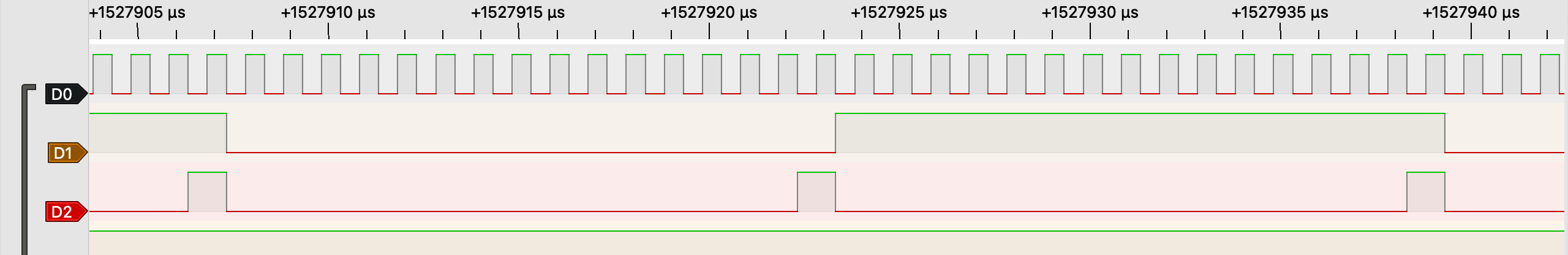
Probing I2S signals into such a tiny chip is impossible (almost), so there is a switch in the code that re-routes I2S to the exposed touch pads. The 16-bit 0x0105 pattern is a good one when wrapping my head around the timings.

Now that the MCU carries USB, we no longer need a separate debug connector. When a specific pin (PB22) is shorted to ground at boot, the device enters the factory bootloader which allows program upload through USB. Here, during normal operation, PB22 functions as the activity LED's cathode, so entering bootloader is as simple as clipping specific points on the board with a tweezer.

Now, what is CC, you may ask? It stands for anything — from Control Change to "Creative Customization", you name it. Canta stays the title, and the codename CC I leave up to the user to interpret. I'd like to see the USB customization working soon, whether by some simple parameter knobs or by full-on RISC-V code upload — the possibilities are endless, as I might conclude from my curious-minded friends.
For now, the music comes back alive. Until next time, have a fabulous late-season!
This revision's work-in-progress is at the cc branch.
-
Crossing the finish line
07/24/2024 at 08:10 • 0 commentsWith the curtain call of the contest, this project is also reaching a milestone!
![]()
Since the last update, I have mounted the LDO (the TLV702), which proved sufficient to eliminate the variance in voltage drop together with the noise, yielding a clean sound. I have also tuned the sensing algorithm to reduce accidental triggering and improve sensitivity in the case of a floating ground (e.g., a portable power bank); a benefit of using a microcontroller over specialised touch-sensing ICs is the ability to fine-tune the triggering thresholds and filtering algorithms, taking into account the electrode layout and application specificities (e.g., adjacent keys tend to trigger incorrectly), without having to replace physical components.
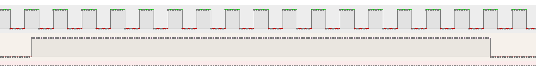
In the hope of improving robustness, I inspected the audio bus (LSBJ) with a logic analyser. It appeared that the signals were slightly misaligned, so I adjusted the timing offsets to achieve an ideal alignment among the signals. The inline assembly block also underwent a bit of rewriting, getting rid of an excessively long nop sequence.
Before (BCK vs WS; BCK vs DATA):
![]()
![]()
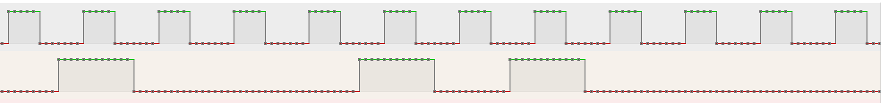
After (BCK, WS, DATA):
![]()
With all that done, here it is!
This ended up missing the Madman Muntz special mentions — I guess I need to get madder 😈 (But it did get featured on the Hackaday.io Bits newsletter! 🌟) The challenge really saw exceptional creativity in every aspect — please check out the winners’ announcement and all the projects in the challenge!Thank you for getting this far. I will make sure to update here whenever this gets further updates, but meanwhile, see you in the Tiny Games!
-
Revision 2
07/11/2024 at 12:53 • 0 commentsAfter a short pause, here comes a revision!
![]()
Shortly after the last update, I investigated the buzzing issue — its frequency was not constant (e.g., around 270 Hz with an Apple adapter, and variable with a power strip) and was present with some of the portable power banks, so mains hum cannot be the root cause. I eventually concluded that it was the supply noise of the USB 5 V, probably due to switching noise in the power supply devices. The frequency and intensity matched the 5 V bus noise on the oscilloscope.
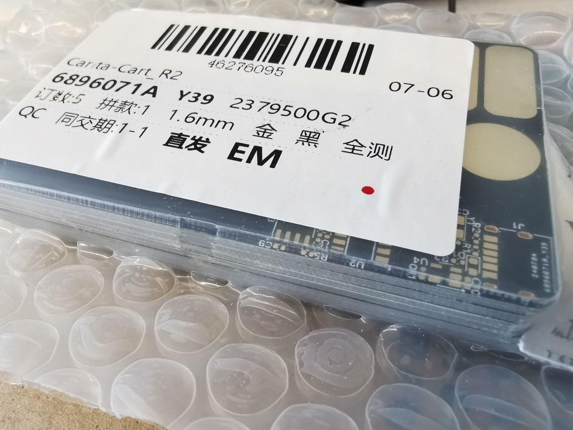
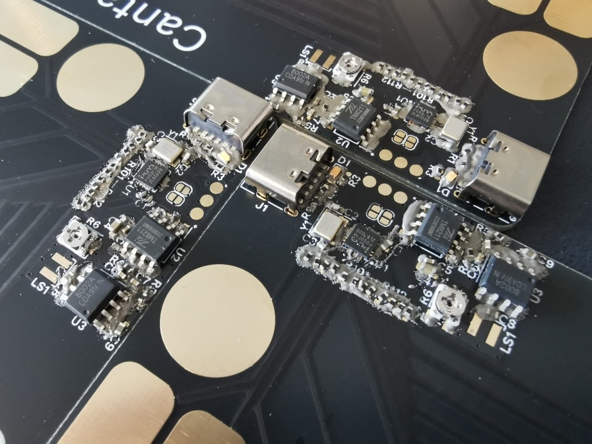
To get around this, I added an LDO (TLV70245) to obtain a low-noise 4.5 V supply line. I also replaced the individual 1 MΩ resistors with quad-0402 resistor arrays. Microcontroller pins were reassigned and tracks re-routed, both in order to further reduce broken signal paths. And this yields the second revision. — Wait, the house produced seven copies when I ordered 5?
![]()
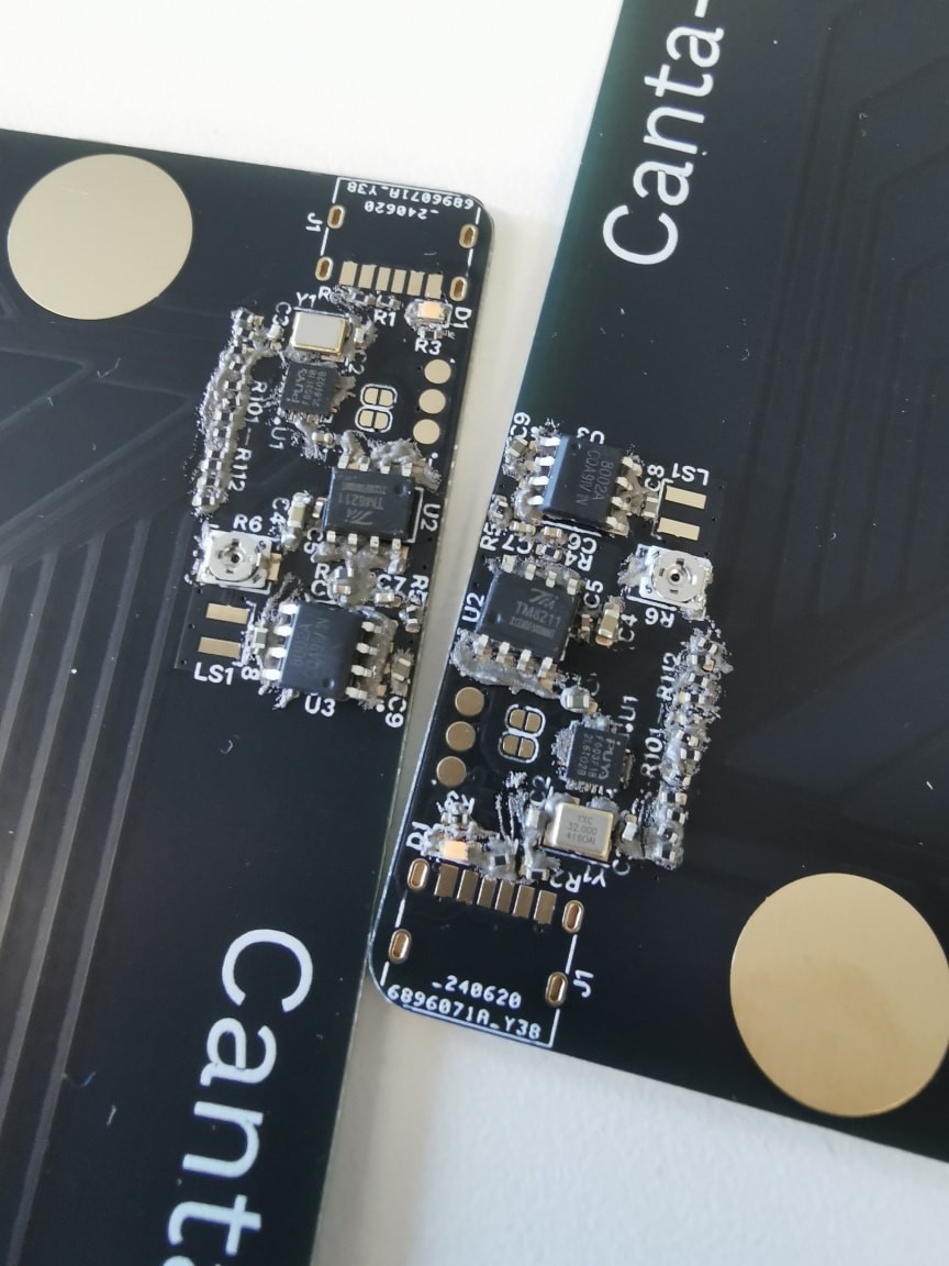
Assembly was largely the same. Resistor arrays are a bit easier to handle than individual components, but not by much — bridges and opens happen, and these can require quite some patience to repair after the speaker has been soldered on, as the plastic casing cannot stand high temperatures.
The twist this time is that I forgot to order the TLV702. The pinout was compatible with my stock SPX3819, so I used that instead. It gives 3.3 V, but that is sufficient for testing. After pin reassignment, the bit clock (BCK) signal is no longer supplied by the SPI clock and is instead generated by a timer (TIM17) running PWM at the same rate. In firmware, this needs another synchronising effort inside the inline assembly block, but it went rather smoothly minus a few detours caused by hidden soldering defects preventing audio signals from passing through.
It works, and the buzzing noise is indeed gone. However, there is now a hissing artefact during the attack/release phase of sounds (i.e., when the volume changes). I suppose this is due to variations in drop-out with output current. Insufficient input/output capacitance might be a problem here; I used 1 µF as is recommended by the TLV702 datasheet while the stand-in SPX3819 calls for >2.2 µF. It remains to be seen how TLV702 will perform.
That apart, the updated revision works quite well. I’ve been struggling to find a place to take a recording — in every quiet place, there will be people to be disturbed by sound. Strange, isn’t it? Even during this lonely time of the summer holidays, I still find myself always surrounded by the herd. Humans are gregarious animals, after all.
-
Fixed. Fixed…?
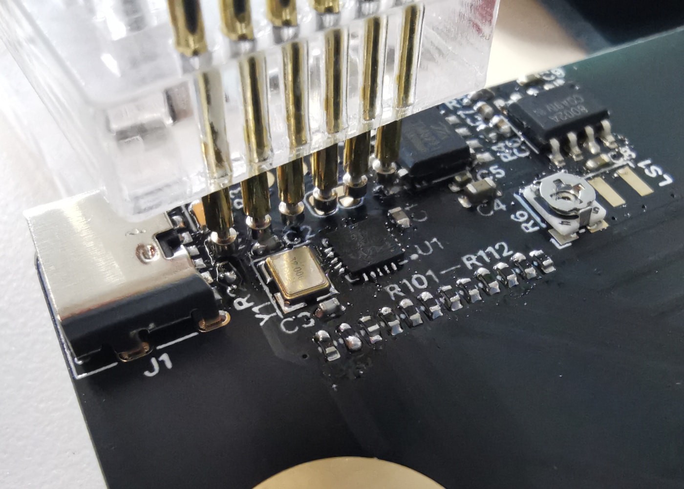
06/28/2024 at 19:09 • 0 commentsDebugging gets quite hectic without a correctly pitched probe header, rendering two hands and ten fingers inadequate, but the new probes I ordered several days ago has arrived this morning — what better day to make the final push?
Three more assemblies. This has become my first PCB prototype batch that all got assembled.
![]()
![]()
Instead of the original intended speakers, I went for ones of a larger type, also rated 8Ω 1W, but free from distortions at the desired amplitude. The sounds came out quite clear.
![]()
Spread some cleaning agent on the boards, and wash it away with water. Everything was good, except that the speakers all got stuck onto the board. It would not move a bit, failing all attempts with tweezers, jumper wire headers, and safety pins. I don’t know the exact reason, but I suppose it might be the organic compounds in the solution melting the plastic…? Maybe I can try re-applying the cleaning agent to see whether it can be removed this way. There is a Chinese idiom that goes, “to remove the bell from a tiger’s neck, it calls for the very person who tied it there” (解铃还须系铃人). Well, it may as well apply here.
That aside, now that everything seems ready…
One last remaining issue (for this revision) is that the device makes a continuous buzz if plugged into certain types of power sources (e.g., USB receptacles on power strips). A laptop’s USB outlet presented no problem. I can’t find my portable power bank, so that remains unknown, but I speculate that it should work fine and the noise comes from mains hum. But that is left to be checked against later!
-
Quick update: it's working
06/27/2024 at 18:38 • 0 commentsThings go on in life, but it's been quite smooth sailing regarding this little one.
Firmware development was a breeze — Puya provides a library package that is largely compatible with STM32's HAL in terms of concepts and conventions. I2S audio was emulated with DMA-driven SPI plus a timer outputting PWM. The entire instrument works as intended. I'll record a video soon!
One major setback is that the 20-mm 8Ω 1W speaker is proving inadequate, causing noticeable distortion in the sound — the issue disappeared when I replaced the speaker with a larger one rated 4Ω 3W. Seems like something to be thought over.
-
Hands dirty! But…?!
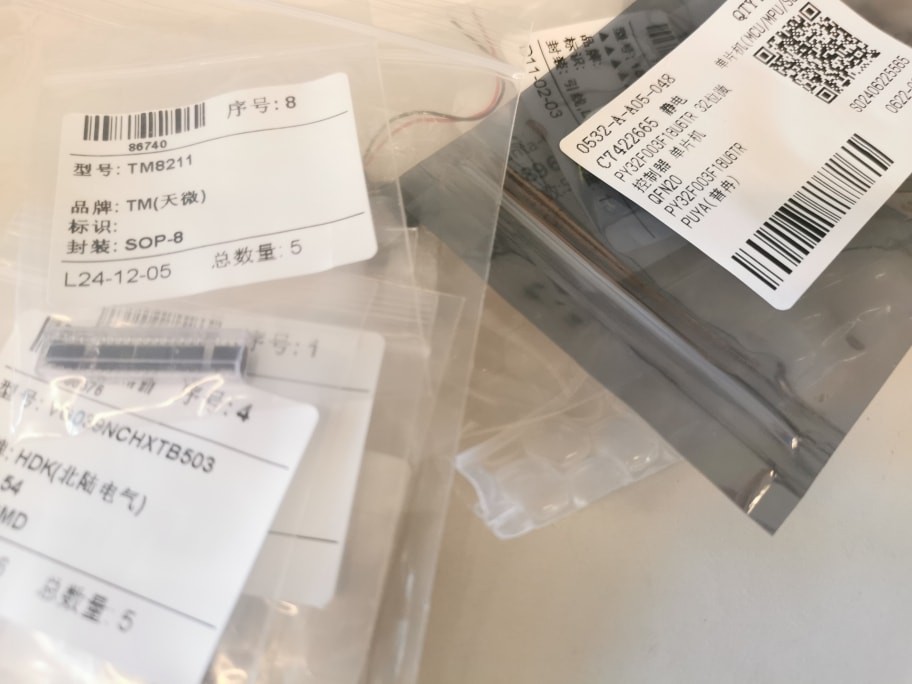
06/24/2024 at 17:51 • 0 commentsThe board and the components have all arrived!
![]()
![]()
Applying solder paste by hand. I did not rush to a stencil as I felt there were too many moving parts this time — all the ICs on this board I have never worked with before, so I’m actually expecting revisions before a finalised design.
![]()
Soldered everything with a hot air gun. 0402 packages are quite a bit naughtier than 0603’s, especially when you’re dealing with a row of black resistors being nudged around on black solder mask! I think I’d switch to a resistor array if I’m doing a revision.
Alcohol cleaning left some white traces of solder flux on the board, so I tried the cleaning agent for the first time. It smelt strange even through a face mask (stranger than any solder flux I’ve encountered), but worked out pretty well.
![]()
We’re finally ready to launch the MCU and start blinking!
Now comes the twist: I cannot find my DAP debug probe. I remember nothing about its location despite an exhaustive search. This got me stuck for two hours, I guess this is just part of my ordinary ADHD engineering experience. Well, that does not stop me by a least significant bit. Just flash a Raspberry Pi Pico with the debug probe firmware. Voilà! A new probe! Then solder wires to the test pads and the power line. Now there doesn’t even need to be a clip to hold the probes, as these jumper wires can be simply plugged.
![]()
I know, the orange wire fell off very quickly. Once it was fixed, I was able to run pyOCD and flash the firmware through the Pico probe. Does it work? There is no activity LED on this board, but the DMM looks at pin A0 — accessible at one of the touch pads — and says yes, it toggles.
That might not seem like much progress, but that concludes the day well anyway. How will things be going tomorrow? I’m getting curious as I practise on the simulator ^ ^
-
Getting started, with a simulator in the browser
06/24/2024 at 07:39 • 0 commentsHi all! This is my first project log on Hackaday.
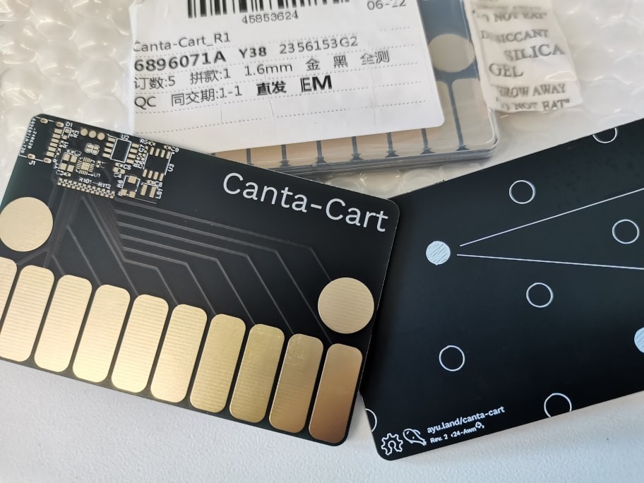
This project, Canta-Cart, is a card-sized musical instrument with touch keys — to be an entry to the Business Card Challenge. It comprises 10 keys that make sounds of a diatonic major scale (spanning a tenth interval) and 2 transpose buttons for accidentals and overall transposition.
The design of the electronics has been completed. While they are on their way from the factory/warehouses, I have implemented a simulator on the desktop computer (also ported to the web browser) as a testbed for synthesiser and interaction design. It worked out quite well — tunes can be spelt out without friction on this keyboard; harmonics and musical textures are achievable, especially on the smartphone touchscreen, which is free from the limitation of key conflicts.
This simulator is now live at https://ayuusweetfish.github.io/Canta-Cart/synth/. It supports touchscreens and computer keyboards and has help information built-in.
Meanwhile, I've also looked into how the PY32F003 microcontroller works. This is selected in favour of my go-to STM32G0 in order to reduce the overall cost — at 1 Chinese yuan (US 15¢) it brings the entire device even closer to a business card to give away lots of. Resource material on it does not seem abundant, but after a bit of scouring I managed to put together a minimal, stripped-down LED-blinking firmware project. It compiles, but I'll have to wait until the components arrive to test whether I've got anything off-track.
The circuit board and the components are expected to arrive tomorrow, after which I will get down to the workbench to assemble the parts. Let's look forward to it.
 the speaker with wires soldered on; (2) the speaker soldered to the board.")