Demo/introductory video available at:
https://www.youtube.com/watch?v=DMrWX3kyayo
An unholy marriage of an Arduino, an ATX power supply and a Raspberry Pi.
To make the experience fit your profile, pick a username and tell us what interests you.
We found and based on your interests.
Demo/introductory video available at:
https://www.youtube.com/watch?v=DMrWX3kyayo
There are many flavors of Linux available for the Raspberry Pi, so I will focus on the generic Raspbian build as well as one for Arch Linux. Why Arch? I am using MinePeon in my Bitcoin mining rig!
Raspian:
First, install git if you haven't already:
sudo apt-get update
sudo apt-get upgrade
sudo apt-get install git-core
Download wiringPi and install it:
git clone git://git.drogon.net/wiringPi
cd wiringPi
./build
Create the shutdowncheck script:
cd ~
sudo nano shutdowncheck
Type the following into the nano text editor:
#!/bin/bash
PATH=/usr/bin:/home/pi/wiringPi/gpio
echo "Shutdown script starting..."
echo "Asserting pins (7=in, low(pull-down); 8=out,high)"
gpio -g mode 7 in
gpio -g mode 7 down
gpio -g write 7 0
gpio -g mode 8 out
gpio -g write 8 1
COUNTER=0
while [ 1 ]; do
if [ "$(/home/pi/wiringPi/gpio/gpio -g read 7)" = "1" ]; then
echo "PIN7 requested a SYSTEM HALT!"
sudo halt -p
break
fi
sudo sleep 0.5
done
exit 0
After you have typed this in and double checked your work, press ctrl-o (to save) and ctrl-x (to exit).
Next, make the script executable:
sudo chmod 755 shutdowncheck
Why type? Why can't I just pull it from your github? Because you can learn a bit about how gpio works on your pi by typing it manually. Also, some distros interpret new lines differently and you may end up with a non functioning script.
Edit your /etc/rc.local file and add the following line before the last line (exit 0):
sudo nano /etc/rc.local
Add this line before exit 0:
(cd /home/pi && exec ./shutdowncheck) &
Save (ctrl-o) and exit nano (ctrl-x). Now your script will run automatically when your Pi starts up!
Arch Linux (MinePeon specific instructions)
Special thanks to synapseattack from bitcointalk.org for the MinePeon instructions!
Download wiringPi and install it:
git clone git://git.drogon.net/wiringPi
cd wiringPi
./build
sudo cp /home/minepeon/wiringPi/gpio/gpio /usr/bin/
Create the shutdowncheck script:
sudo nano /usr/bin/shutdowncheck
Type the following into nano and then hit ctrl-o (save) and then ctrl-x (exit):
#!/bin/bash
PATH=/usr/bin
echo "Shutdown script starting..."
echo "Asserting pins (7=in, low(pull-down); 8=out,high)"
gpio -g mode 7 in
gpio -g mode 7 down
gpio -g write 7 0
gpio -g mode 8 out
gpio -g write 8 1
COUNTER=0
while [ 1 ]; do
if [ "$(/usr/bin/gpio -g read 7)" = "1" ]; then
echo "PIN7 requested a SYSTEM HALT!"
sudo halt -p
break
fi
sudo sleep 0.5
done
exit 0
Make the new file executable:
sudo chmod +x /usr/bin/shutdowncheck
Now make it a service:
sudo nano /usr/lib/systemd/system/shutdowncheck.service
Type this into nano (ctrl-o and ctrl-x to save and exit):
[Unit]
Description=ShutdownCheck
ConditionFileIsExecutable=/usr/bin/shutdowncheck
[Service]
Type=forking
ExecStart=/usr/bin/shutdowncheck
TimeoutSec=0
StandardOutput=tty
RemainAfterExit=yes
SysVStartPriority=99
[Install]
WantedBy=multi-user.target
Now enable your new service:
sudo systemctl enable shutdowncheck.service
Now your script will run during boot (you will need to reboot after enabling the service).
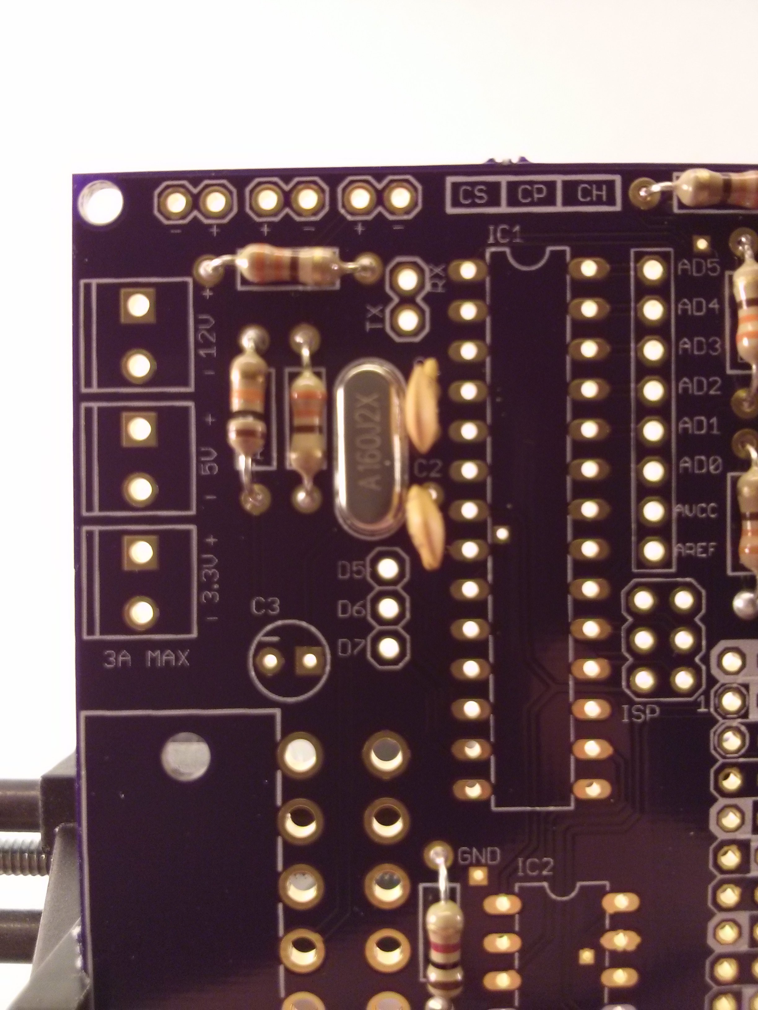
To assemble your ATX-Pi you will need the following tools: soldering iron, right angle wire cutters, and a roll of solder. Optional, but encouraged: a PanaVise Jr. or set of "helping hands" soldering clips.
Step one: Place the 330 Ohm resistors on R1-R5 and solder in place. Bending one of the pins on the resistor helps hold it in place.

Step two: Place the R6 (1k ohm), R7 (10k ohm), the 16 MHz crystal (XTAL) and the 22 pF capacitors (C1/C2). Solder in place.

Step three: place the USB-A port on the board and solder in place, starting with the pins on the underside of the board. Next solder the 4 pins on the top.

Create an account to leave a comment. Already have an account? Log In.
I'm interested in this project because I have a RPi hooked up to two external hard drives. I want to power all three using an ATX PSU. Is that possible?
Hello pipeman. That should be possible but it really depends on how the hard drives are powered. Can you supply more details about the hard drives or your current setup?
I'm sorry I didn't see your response before now. I'm using two WD 3TB Red series hard drives. They currently are hooked to the RPI using two "SATA to USB" adapters. The whole setup is shoved into a mini ITX case. That's what gave me the Idea of using an ATX power supply to provide power to the RPi, and the hard drives, from one source instead of 3 different sources, like it is now. Let me know if you need more information.
Am I correct in assuming that the USB adapters have separate power supplies? What sort of connectors are involved here? Do they use separate connectors for power and data on the hard drive end? If so you could just hook up SATA power connectors straight from the power supply. If the adapters themselves need to be powered you may have to break out the soldering iron and adapt a Molex connector, but as long as the adapters work at 5V that shouldn't be an issue either.
Yes, the USB adapters have separate power supplies. each power supply has a molex connector that connects to an adapter that connects directly to the SATA drive. You can see what I mean in this picture: http://goo.gl/FzB32W I think you answered my question with your last post. I just didn't know, with your device, if the ATX PSU would still operate as it normally would and power the drives too. Do you still offer the ATX-Pi kit? I would be interested in purchasing one.
I used to have one of those adapters myself actually, it was quite handy. You should be fine hooking up SATA power connectors directly from the PSU, as long as the adapter will draw it's own power from the USB connection to the Pi (I never used it in this configuration). I would NOT recommend using the included power adapter at the same time you have the PSU hooked up to the drives.
For me, an important design decision was to not require modification to the power supply. You will need an ATX 2.0 compliant PSU, and it should operate normally. Honestly, you could achieve the same effect by shorting the green wire (PS_ON) to ground while you want to have the PSU running. I designed this board to be a bit more elegant than a paper clip though, with a solid connection to the 24-pin ATX plug and a standard USB connection to deliver 5V to the Pi.
Unfortunately I sold out of my kits on my Tindie page and decided to "retire" the product there since they weren't exactly flying off the shelf (admittedly it is a very niche product). Please check my GitHub at https://github.com/KD8SSF/ATX-Pi . I have all the necessary "Gerber" files for board production with either OshPark (recommended) or SeeedStudio (a bit slower to receive the board but could be cheaper). There is also a full parts list and the Arduino code located there if you want to put one together for yourself. Good luck!
Become a member to follow this project and never miss any updates

 Anton
Anton
 Coders Cafe

 Dmitry
OK, thanks for the information. I really appreciate you getting back to me.