Close
0%
0%

WellWatch

Hacky project that monitors the water level in a well as it fills.
Glorified solenoid switch w/ some creature comforts.

Similar projects worth following
465 views
0 followers
During summer droughts we use a shallow well as a holding tank for irrigating the plants around a farm. The issue is, the well is VERY shallow, and the farmers (my parents), are somewhat forgetful. One too many times, the area has unintentionally turned into a swimming pool. This wouldn't be too much of an issue (albeit wasteful), if it weren't for the animals directly surrounding the impromptu pond. (Chickens much prefer dirt baths to the more conventional kind). I couldn't find any simple/cheap solution off the shelf so I thought I'd hack together a system. Hopefully this simple cutoff will reduce the predisposed probability of pond...

In the future I'll redesign this circuit more professionally, but for now its just hacked together with what I had lying around.

Current Project Status

=== Prototype ===

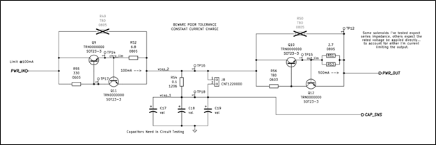
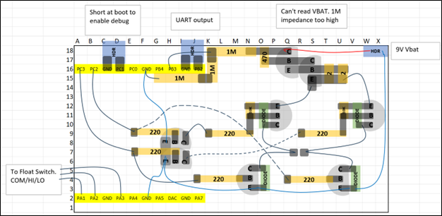
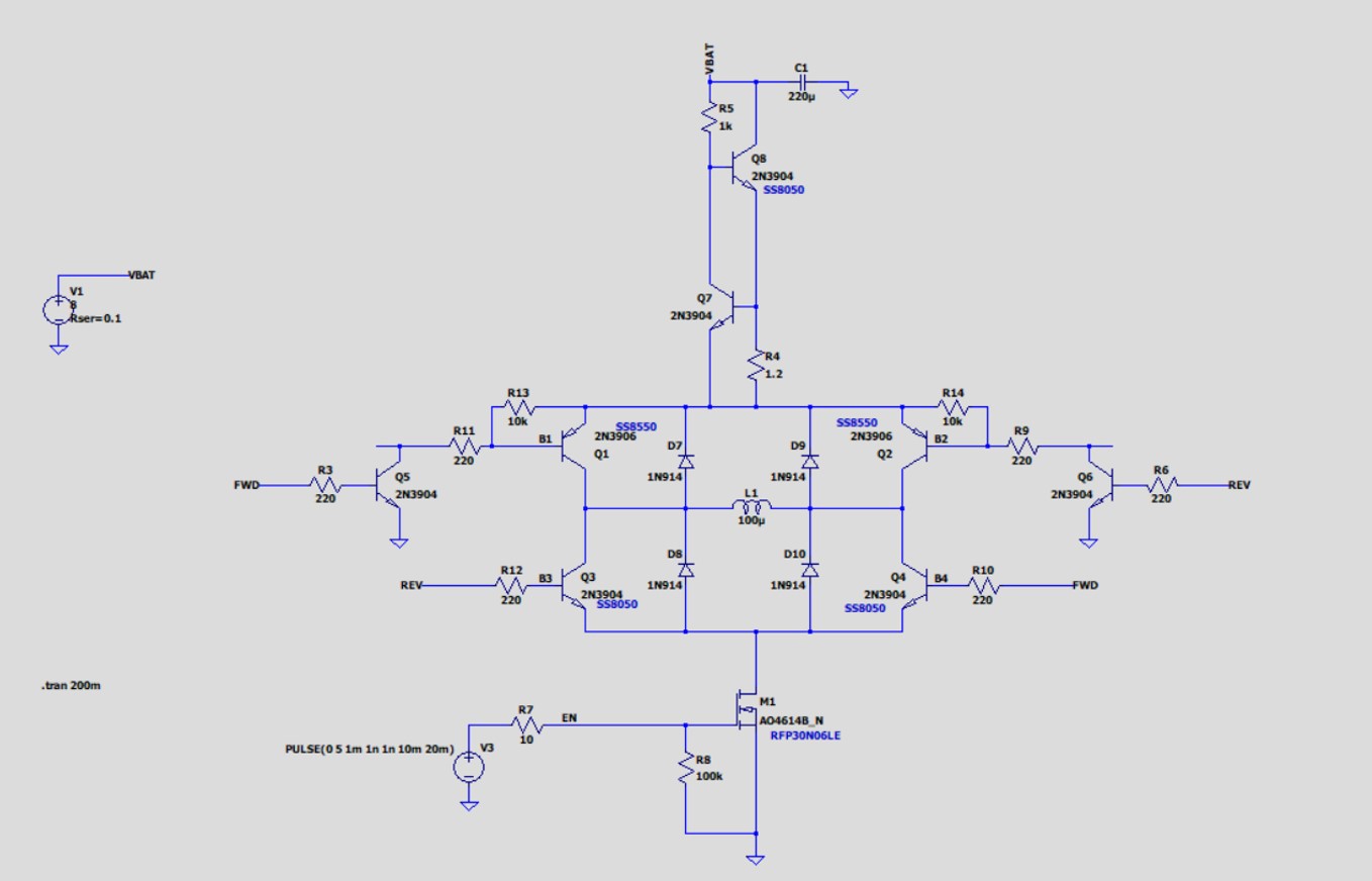
Circuit Design -------------- ( ✓ )
Breadboard Proto -------- ( ✓ )
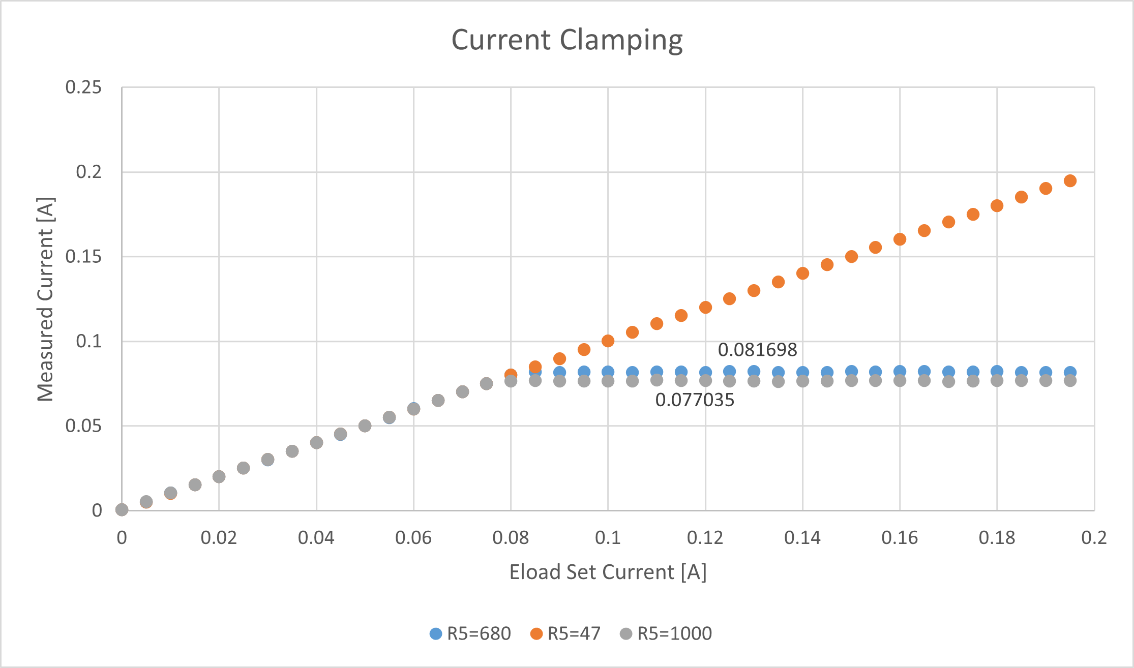
Power Analysis ------------ ( ✓ )
Firmware Dev -------------- ( ✓ )
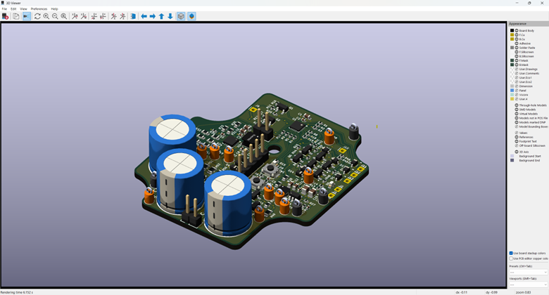
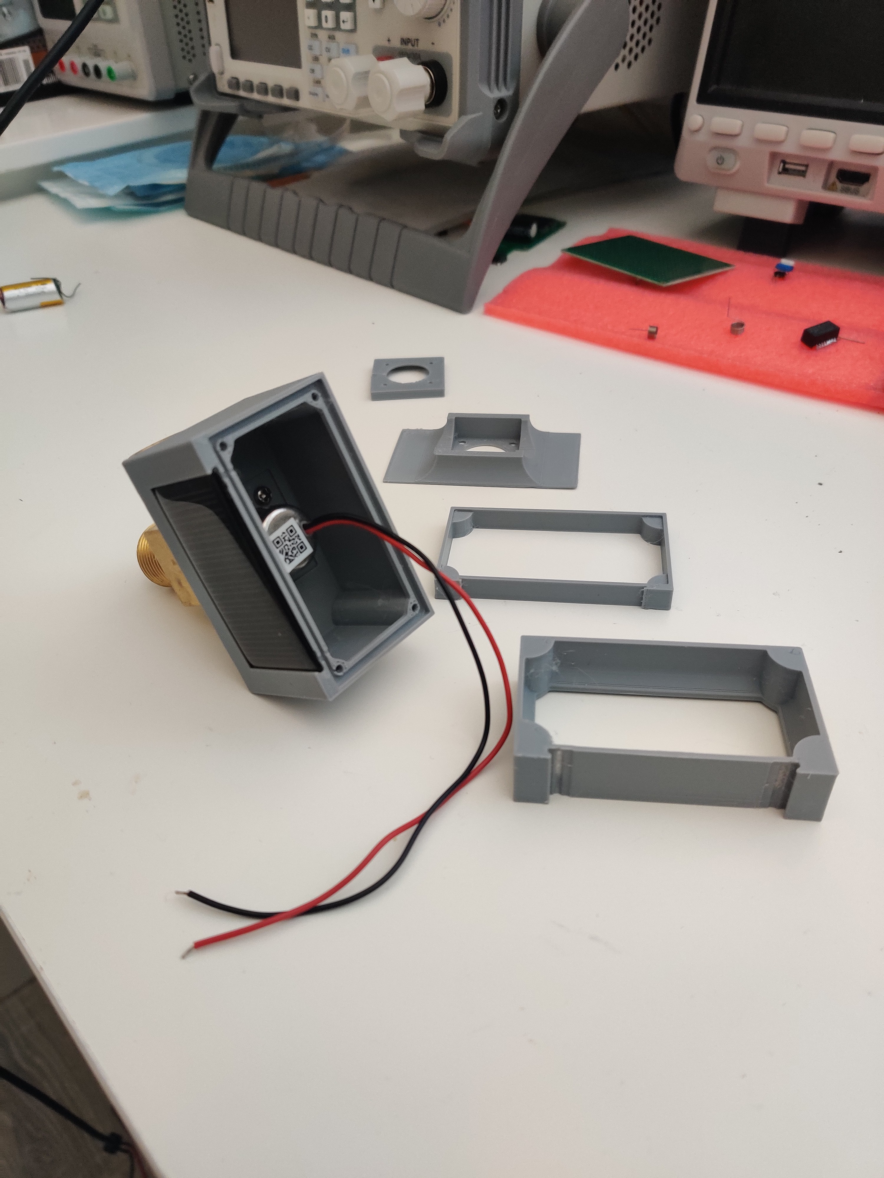
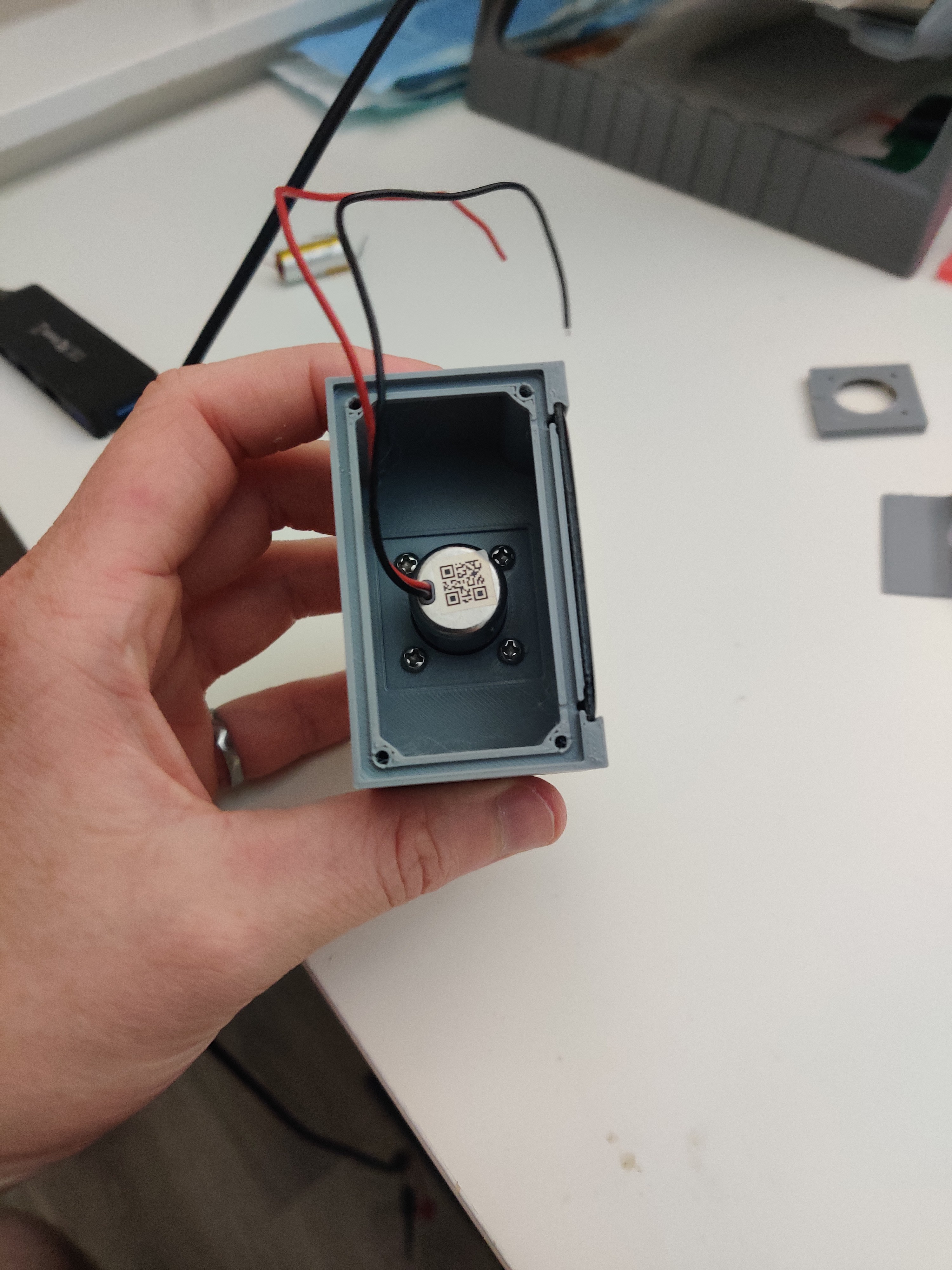
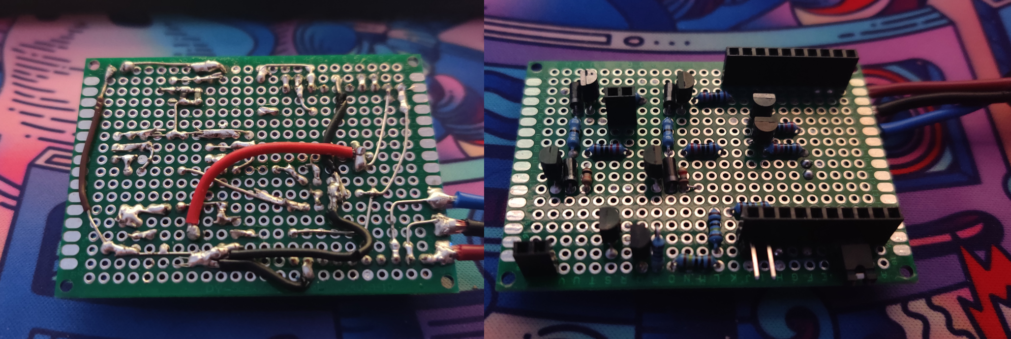
Perf Board Proto  --------- ( ✓ )
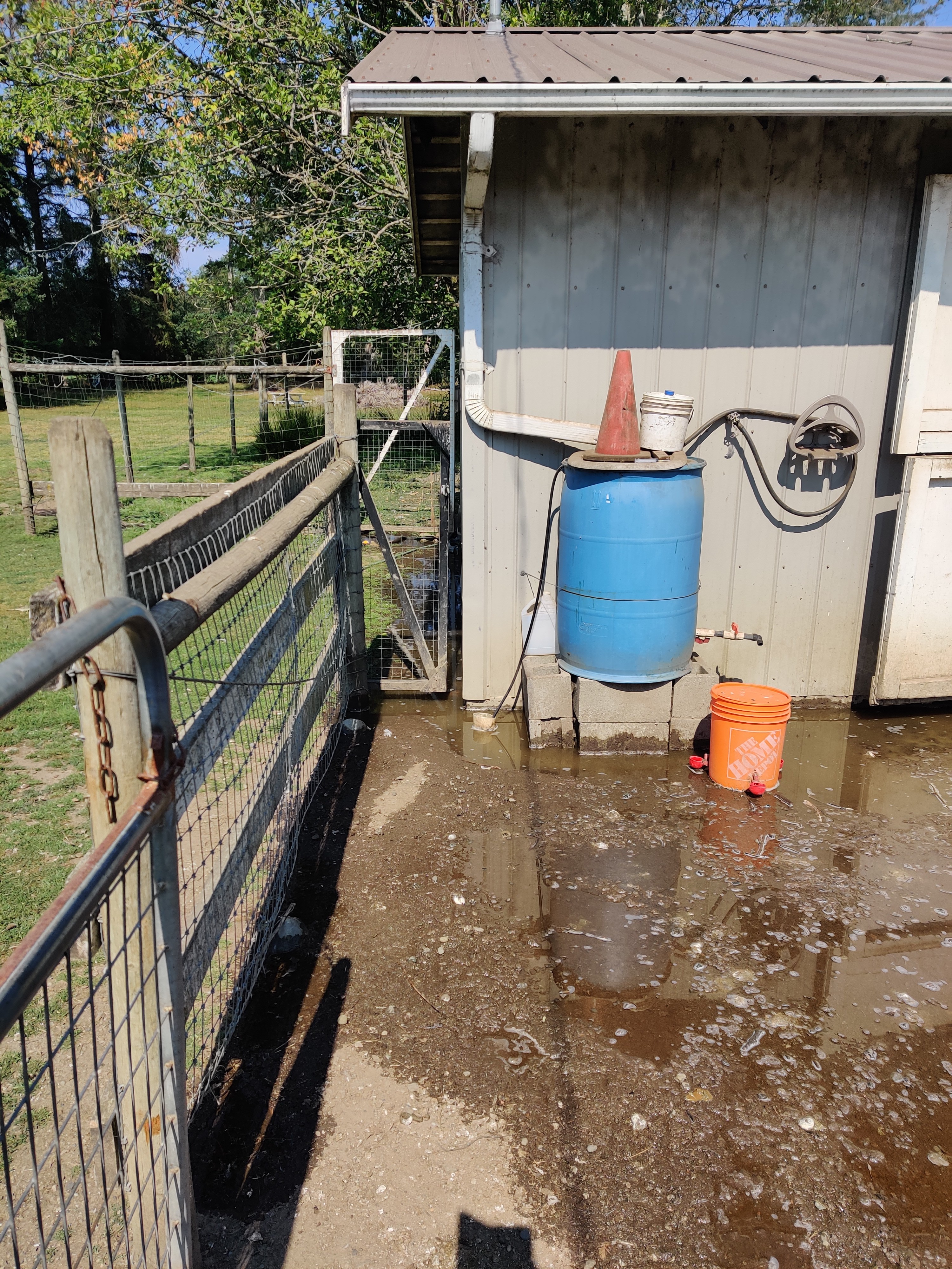
Deploy ----------------------- ( ✓ )


=== REV0 ===

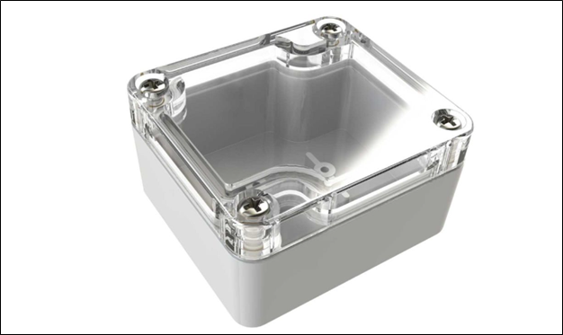
Case Development --------- PENDING
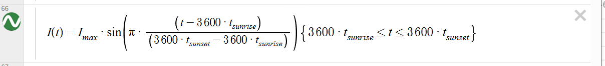
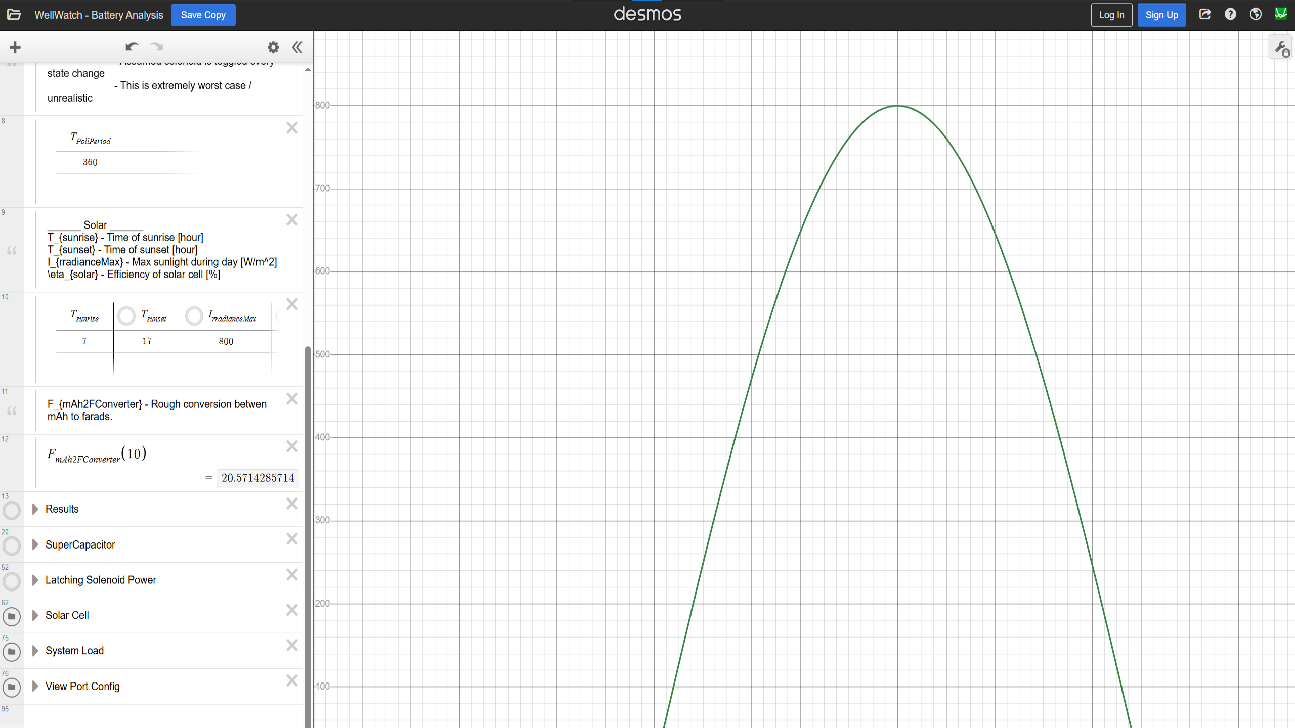
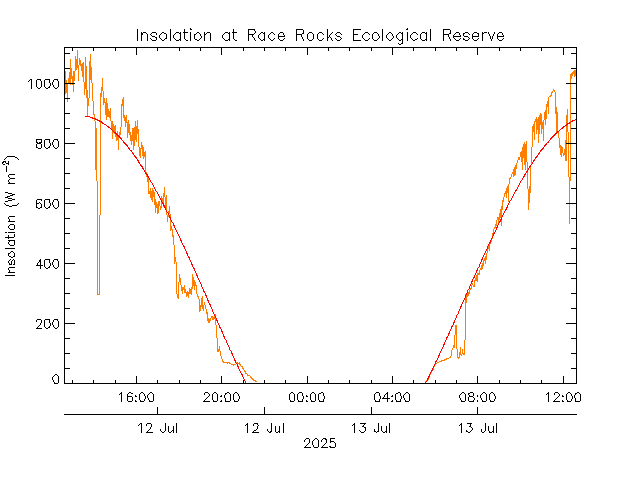
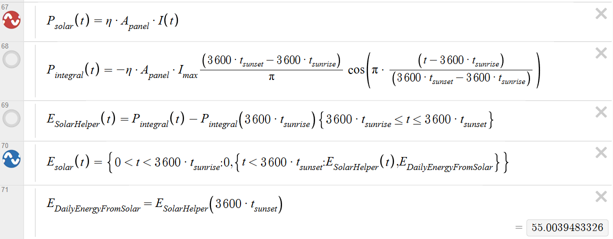
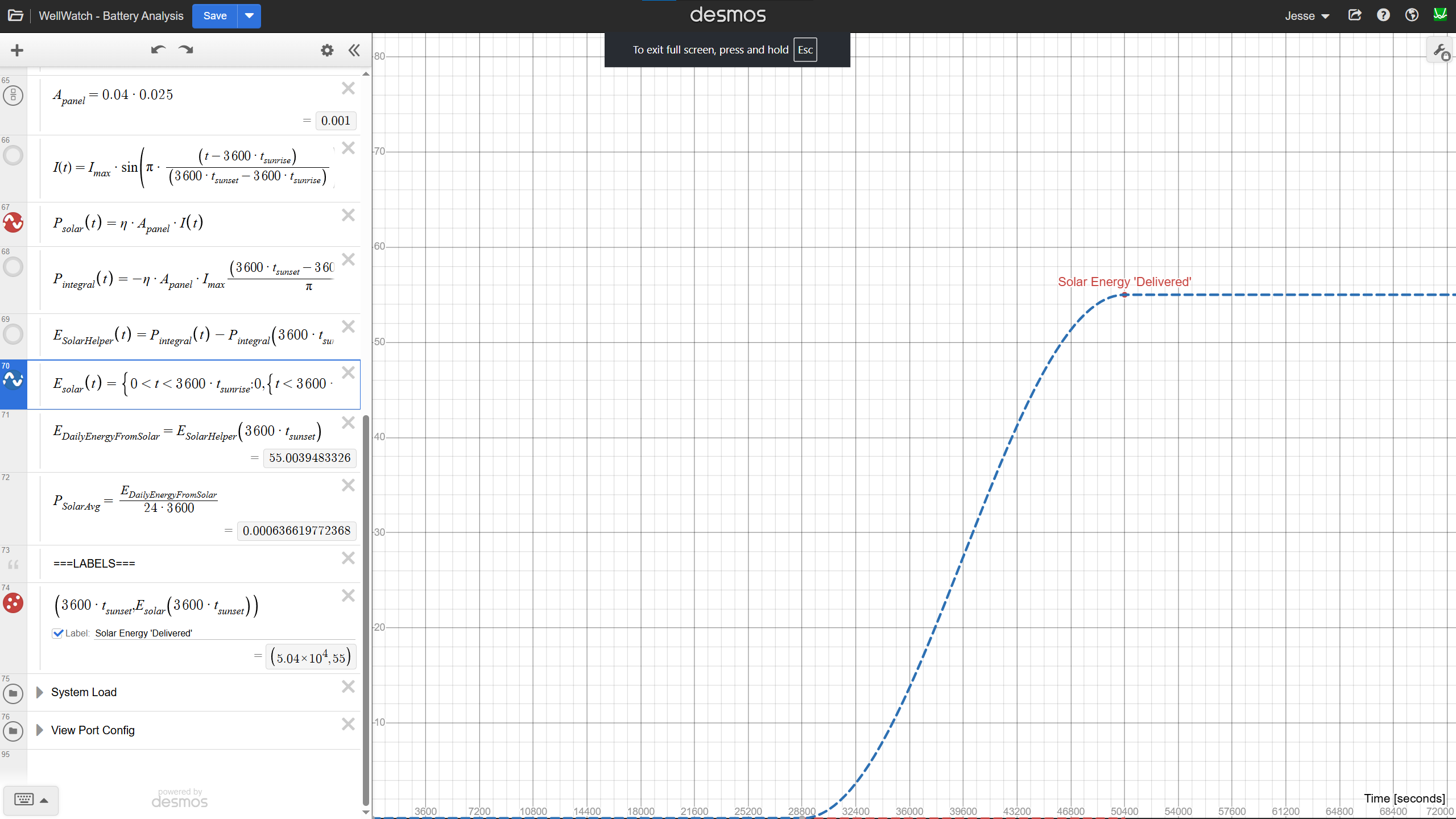
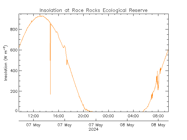
Solar Feasibility -------------- PENDING
R&D Misc ---------------------- TBD
Schematic --------------------- PENDING
Layout -------------------------- PENDING
Documentation ------------- PENDING

HBridge_CurrentLimit.asc

HBridge Simulation w/ Current Limiter (LTSPICE)

asc - 5.57 kB - 07/25/2024 at 03:28

Download

  • Design Update - PCB & SCH Work

    Jesse Farrell28 minutes ago 0 comments

    With Christmas PTO fast approaching I thought I’d focus on finishing up some projects. My goal is to order PCBA to tinker with over the holidays.

    A quick overview of the “WellWatch” project. This widget essentially just monitors a float switch/gauge and toggles a solenoid accordingly (see the project homepage for why I’m doing this). Some challenges that make this project a bit more interesting is (1) the system will be operating from a Solar cell, and (2) it will support a variety of switching voltages.

    The core blocks of the system are shown below and include Power (PWR), Microcontroller (MCU), Pulse storage, and H-bridge.


    PWR – Harvests energy from solar cell and stores that energy in a single 400mAh LIPO cell. Battery voltage is exposed on VBAT, and a regulated version of VBAT is exposed on VOUT. When BST_EN is asserted, BST_OUT generates between 5 – 24V depending on the hardware configuration.

    MCU - The microcontroller block contains an ATTINY1616 which; controls the H-bridge circuit via SOpen and SClose (solenoid open/close), senses the state of the float switch via GPIO_HI, GPIO _COM, and GPIO _LO, and measures VBAT as well as the pulse energy storage capacitors.

    H-Bridge – This circuit is fairly generic. The only slight deviation from a jellybean H-bridge is the addition of Q6 and Q5 which allows me to control all 4 driver FETs with two signals, OPEN and CLOSE. I still need to fine tune my component selection to reduce the leakage presented to the PWR input.

    Pulse Storage – This is another energy storage circuit (not the LIPO battery!!) which provides the 50ms (typ) pulse of current required to toggle a latching solenoid. The schematic shows two active current limiting circuits. Capacitor charge current is limited by Q11/Q9, and capacitor discharge current is defined by Q10/Q12. Charge current will be configured to align with the capabilities of the boost converter, and the discharge current will need to be configured for the selected solenoid.

    Anyways… that’s the circuit and here’s the PCB I developed this weekend. I’m just working on some final cleanup. I also need to add a few extra 0ohm resistors to isolate each circuit block. Jumpers are great for debugging and general V&V work for an early design.


    One last thing… If you’re wondering why I set the board outline above, plan to assemble the project in this enclosure from polycase (https://www.polycase.com/wc-20). The LIPO battery is harvested from an old “disposable” vape. My current plan is to rest it ontop of the northern end of the PCB (TPs will need to be removed later). I still am somewhat debating using a LIC instead of a LIPO, but for now I’m prototyping with a LIPO.

  • Lithium-Ion Capacitor, Feasibility

    Jesse Farrell07/14/2025 at 02:51 0 comments

    Its summer again, so the priority of this project has once again been bumped to the top of my list. Funnily enough the prototype project started just last week one year ago… in my defense though I was busy last weekend, if not for that maybe I would have done my first revisit post EXACTLY one year later.

    I fell deep into a power budget rabbit hole this weekend...

    I’ve been interested in hybrid capacitor technologies for some time now, and this project presented a perfect opportunity to evaluate one on paper: the Lithium-Ion Capacitor (LiC). Compared to conventional lithium polymer batteries, LiCs offer some intriguing benefits. However, their primary drawback is energy density, which is lower than that of a lead-acid battery. 

    My goal in this post is to investigate the feasibility of using a LiC for energy storage in this project.

    Modeling the System

    To evaluate whether the lower energy density, and therefore reduced capacity, of a Li-Ion capacitor is feasible for my application, I needed to model the stored energy in the system over a full 24-hour cycle.

    The model had to be detailed enough to capture subtle droops in stored energy. This allows me to then assess voltage margins ensuring that the system remains operational throughout the day. In particular, I’m focused on tracking the minimum voltage across the energy storage element.


    Solar Subsystem

    Irradiance Waveform

    To begin modeling the solar input, I approximated the irradiance over a 24-hour period using I(t). Using a sunrise at 7 AM, sunset at 5 PM, and a peak irradiance of 800 W/m², resulting in the below plot…

    To validate the model, I compared it to real-world data from a nearby Ecological Reserve. The overall trend aligns well (Albeit less noisy).

    From Irradiance to Power

    Next, I converted the irradiance to instantaneous power using the specs of the SP-53X30-4-DK solar panel. While the datasheet reports its dimensions as 53×30 mm, the effective area seems to be closer to 48×25 mm. The devices maximum output power is 0.21W, and its efficiency is 18.6%.

    The instantaneous power equation becomes….

    Solar Power Over Time (Energy)

    The energy provided by the solar panel will be the area under the curve of P_{solar}. Desmos has an integration function, but I find it causes the system to lag badly. Doing this by “hand” I get the equations below. We have to be careful with the start and stop points of our integration, since the solar panel will (obviously!) only provide power from sunrise to sunset.

    Model Assumptions

    It’s important to note the approximations made by this model. Critically, I’ve ignored the efficiency of the energy harvester IC, and I’ve ignored several nuances of the solar panel such as thermal influence and MPPT (maximum power point tracking). 

    These assumptions are tolerable for early-stage feasibility, but would need to be revisited for the final design (or just tested in the field).
    Solenoid Subsystem

    Now that we’ve characterized the incoming solar power, let’s turn our attention to the main energy consumer, the solenoid subsystem.

    Every <to be determined> seconds, the system updates its state. During this update it sends a 50 ms pulse to either open or close the solenoid. Each time drawing 2.5 W, which equates to 0.125 J of energy.

    Assumptions

    Luckily modeling this system is very simple, so long as we allow ourselves a few assumptions. Assuming the energy required for a single pulse (0.125J) is insignificant compared to the total energy in the system, then we can say that the drop in energy, and more importantly voltage, from a single pulse will not appreciably affect the system.

    Let’s test that assumption with some numbers… 

    Assuming 1F at 1.5V, a single solenoid pulse will drain the stored energy to 1J (0.5*C*V^2 - 0.125J), which will result in a drop from 1.5V to 1.41V....

    Read more »

  • Enclosure Design

    Jesse Farrell08/03/2024 at 16:36 0 comments

    I've been working on the REV1 enclosure and had to brush off some old CAD skills. Whenever I do 3D modeling I try to do lots of simple test prints... Measure once, print twice I guess. It's much faster than printing the final enclosure and really helps tighten up the design feedback loop. Below are 4 simple test prints, followed by the first prototype of the full enclosure.

    The enclosure will need to be water tight. Water might leak at the (1) lid-case interface, (2) solenoid-case interface, and (3) through the case itself. To avoid (1) I'd like to use either a o-ring or some type of silicone/epoxy in the groove along the top of the case. For (2) I can easily put an o-ring around the base of the solenoid. And to avoid (3) I'll need to coat the cavity with some kind of a sealant, since PLA isn't exactly water tight.

  • Pathetic Prototype Deployed

    Jesse Farrell07/22/2024 at 19:26 0 comments

    The prototype was successfully deployed, and just in time too, as you can see the well was flooded again when I arrived. The setup is very make-shift, but only needs to work for 2-months. I’ll continue to work on a more polished design for next summer.

    There were a couple integration headaches to deal with, mainly finding couplers to connect the hose to the ½’’ pipe threading on my solenoid. Even with the couplers, the hose was fairly leaky so I’m a bit worried about water getting into my enclosure. Luckily I had some marine sealant/epoxy.

    For the next (non-prototype) version I think I’ll try to mount the PCB directly to the solenoid and place a gasket against its side to seal it off. I’ll also need to find a better way to set the float switch’s position. I’m designing a PCB on the side here, so once I’m about to order I’ll post an update. I expect it’ll take awhile though, especially since I have to do some 3D modelling.

  • Power Problems

    Jesse Farrell07/16/2024 at 05:41 0 comments

    How will I power this board? I need at least 5V for the solenoid, and the ATTINY can run off 1V8 to 5V with varied restrictions to its performance. Ideally, I’d just include a low quiescent buck-converter to converter a 9V battery to 5V for the whole system. Sadly, I don’t have a converter handy in my parts bin, so here we are…

    The solenoid was handled in by the original circuit posted here. 9V Vbat will be current limited to ~500mA regardless of the input voltage (within reason!). That leaves the ATTINY and a 9V battery, with no on-hand switchers or even LDO’s that fit the bill. All my LDO’s either didn’t support >7V input, or had a minimum load requirement that would squash the battery life of the board.

    What I did have on-hand was a boost converter (BU33UV7NUX) on the same dev board as my ATTINY. So  I decided to add another battery, two actually (2x AA). This new battery will feed the boost converter that will generate a 3V3 supply for my ATTINY. The boost converter can operate all the way down to 0.6V!

    Sadly, this plan didn’t last long...

    So, I immediately killed my boost converter dev board *face palm*. I hummed and hawed for a while and decided to do something dirty, but easy. Why even bother regulating the supply! Two double A’s will get me around 3.2V -> 2.4V during their discharge. That’s well within the operating range of my ATTINY. I tested the circuit at the new range of Vin, and everything was still functional. 

    Here’s the system running off battery. Everything’s working okay, though at higher quiescent currents then I measured previously. Originally I measured <1uA on the ATTINY, but now I measure 300uA. I suspect I tweaked something in my code during debugging. I’ll hunt this down later. (even at 300uA the current draw isn’t enough to drain the device over the summer, so I could leave it as is… seeing as this is just a prototype).

  • Perf Board Bonanza

    Jesse Farrell07/16/2024 at 05:13 0 comments

    I always regret going down the perf board route. Too many flywire’s and last minute bodge jobs. But since this project is on a timeline, I don’t have much of an option. The circuit hasn’t changed from the last picture, but now includes an ATTINY1616 to tickle the various control lines. See my first project log for the circuit.

    I decided to first sketch the circuit out to roughly floor plan the parts & wiring. The final result looks a bit like the ramblings of a madman, but thanks to the floor planning there were no major miswirings or debugging required.

    And here’s what that looks like in reality…

    I quickly ran into an issue with the ADC leakage current. The leakage current from VBAT to PB3 through the 1Meg resistor, pulled the measured signal down to the almost nothing. In the future design I’ll include a buffer to resolve this issue… but for this perf board version I might just ignore the feature. TBD.

  • Skeleton Code

    Jesse Farrell07/16/2024 at 05:00 0 comments

    I have the hardware figured out and breadboarded, next thing to flesh out is the FW. It’s a VERY simple program. Here’s 4 main basic states.

    • Measure Battery Voltage
    • Poll water gauge
      • To save on battery, I’m going to “poll” the float switch (no pullups!)
      • Send signal on COM and look for signal on either of the two remaining wires
    • Set Solenoid
      • Short 30ms pulse
      • Polarity of pulse dictates whether solenoid opens or closes
    • Sleep & Repeat
      • Go to deep deep sleep
    • If voltage is too low we might decide to shut off the solenoid as a preventative measure… we don’t want to risk losing power while the solenoid is open!
    • We could also monitor battery drain to gauge faults in the system

    I wanted the main data structure to be circular. So, I made a linked list that sort of feeds into itself… this way I don’t have to know the exact location of any data node, and I navigate the structure using node->next or node->last.

    This way I (1) don’t have to keep track of which element I’m on and (2) I get to retain some history of events that I’ve logged. I suspect there’s a less obtuse way of storing this data, but for now this will work (I’m just a HW guy after all!).

    Here’s the main data structure.

    struct DataNode{
      //Debug Data
      bool Init_FLAG = false;              // If initizlized is false, data is potentially NULL
      uint8_t ArrayElem;                   // Defines which element of the array this is
    
      // Data
      uint16_t BatteryLevel;                    //  Measured battery voltage [RAW]
      SOLENOID SolenoidState = UNDEFINED;      //  State that was written to the solenoid
    
      // Pointers
      struct DataNode* last;                  // Pointer to the lastelement
      struct DataNode* next;                  // Pointer to the nextelement
    };
    

     I have to do some initialization leg work to link the “last” and “next” pointers as shown.

      // ============ Variables ============
      static struct DataNode HistoricData[8];    //MUST BE SIZE=8
      struct DataNode* DataPtr = &HistoricData[0];
      uint8_t i = 0;
    
      // Initialize HistoricData[]
      for(i = 1; i<8; i++){
        HistoricData[i].last = &HistoricData[i-1];
        HistoricData[i].ArrayElem = i;
      }for(i = 0; i<7; i++){ 
        HistoricData[i].next = &HistoricData[i+1];
      }
      HistoricData[0].last = &HistoricData[7];
      HistoricData[7].next = &HistoricData[0];

  • Rapid Prototyping

    Jesse Farrell07/08/2024 at 05:25 0 comments

    I originally had aspirations to make this a nicely polished project, but I'm a little too busy to make this a fully fleshed out design before the summer heat really hits. The core of this design is a latching solenoid, and a water gauge. A latching solenoid was critical since this widget will be running off batteries. It allows you to toggle the state of the solenoid by sending a short 5V pulse, once the state has changed the device can be unpowered and it'll hold wherever it was left. 

    The water gauge, or float switch, is pretty simple; its a buoyant cavity on the end of a wire. Inside the cavity is a heavy ball bearing that opens/closes a switch based on the orientation of the cavity. When the water rises, the object floats up allowing the ball bearing to roll to the opposite side of the cavity.

    All that I'm missing is a cheap micro to control everything. Luckily, I have an ATTINY1616 on hand so I'll use that... to be honest, it would be a fun project to replace this entire design with 74 series logic, but given my time crunch I went the "keep it simple stupid" route.

    H-Bridge!!!

    Who'd of guessed.... I need an H-bridge. My supply of P-channel mosfets is VERY low, so I'll have to get by with BJT's instead. It's not ideal, but given the solenoids relatively low power requirements I should be fine (5V @500mA for 30ms). I had to dig fairly deep for a good npn/pnp pair, but I finally found the SS8050/SS8550. They can handle the current, but I’m a little concerned by their Vbe rating… I’ll definitely need to scrap together a breadboarded prototype. Here's the somewhat finalized circuit.

    I’m running it off an unregulated 9V battery, so care to be taken. I added a current limiting circuit (Q7/Q8), to better maintain the 500mA load across the batteries discharge curve.

    Since I’m worried about power consumption, I added a low side switch that completely disconnects the circuit when its not in use (I might remove this later, depending on how tests look). The hope being it would stop any leakage through this circuit, but I’m suspicious it may do more harm then good.

    Lastly, I flipped the polarity on my upper transistors using NPN’s. I wouldn’t be able to drive the PNP’s since my MCU can only output 3V3. The emitter of Q1/Q2 will be somewhere b/w 9V to 5V, so I’d never be able to turn either one off. This has the added benefit of nicely matching the 4x bases of my H-Bridge. Q1 and Q4 can now have their control signals tied together (thanks to Q5’s inversion), and same goes for Q2 and Q3.

    Current Limiter Test

    A quick breadboard test of the current limiter. I connected “VBAT” to a PSU at 9.5V, and connected the output of the current limiter to an ELOAD. At this point I wasn’t sure if I wanted R5 to be on the smaller side, so I tested a couple values shown below. I expected ~70mA current limit, and that’s more or less what I saw. I’d like to do a quick sanity at temperature before I deploy the widget… I know Vbe can vary with temperature, but I forget with what sort of magnitude. (TODO - Investigate)

    The automation only took a view lines of code thanks to an SCPI library I’ve been working on. If you haven’t poked PyVISA yet, I’d HIGHLY recommend it!

    #Overview:
    # Testing the current limiting of my BJT circuit - July2024
    
    from DriversPy.ELoad import *
    USER_Eload_ip = "192.168.1.13"
    
    eload = ELoad(USER_Eload_ip, DBG_Print = False)
    eload.LOAD_OFF()
    
    # VARS
    CR_Values = list(range(0,200,5))
    CR_Values  = [x / 1000 for x in CR_Values ]
    
    # Test CC
    eload.SET_MODE(LoadType.CC)
    eload.SET_CR_VAL(10000)
    eload.LOAD_ON()
    
    
    for R_VAL in CR_Values:
        sleep(1)
        eload.SET_CC_VAL(R_VAL)
        sleep(0.5)
        I = eload.GET_Current()
        V = eload.GET_Voltage()
        print(str(R_VAL) + " " + str(I)+" " + str(V))
    
    eload.LOAD_OFF()


    End Of Day 1

    By the end of day 1 I have all my HW solidified, but there's still some FW that needs to get done, and some bugs that need squashing. The last thing I found today was flakiness reading ADC values from my ATTINY1616.... Read more »

View all 8 project logs

Enjoy this project?

Share

Discussions

Does this project spark your interest?

Become a member to follow this project and never miss any updates