Blade Master
-
Why I’m building a Edge AI camera for student robotics projects
01/30/2026 at 03:16 • 0 comments(This video is a close-up, check the demo in project details page)
Motivation
In 2023, I attended a robotics conference (Amii AI week) and saw a group of students building Duckiebot style autonomous cars. Surprisingly, they still relied on basic OpenCV pipelines for vision tasks.
When I asked why they weren’t using deep learning vision models and runing them on Jetson nano, they said Jetson felt a bit heavy for their project: it took time to find/train good models; software stack (CUDA, drivers) took long to set up; power consumption and physical size didn’t fit small robots well. Also if they used a Jetson nano, did they run everything on it or still needed a rasperry pi for project logic?
It turns out it wasn’t a lack of interest in deep learning — but some dilemma between project constraints and AI system complexity stops them trying edge AI solutions.
Where is the real issue?
Edge AI hardware is not rare. Jetson boards are powerful but heavy in cost, power, and system complexity. Raspberry Pi is easy to start with but struggles with real-time neural networks. OpenMV lowers the barrier further, but with limited model capability.
These tradeoffs point to the real issue: AI system complexity. In most embedded projects, vision is only a small part of a larger project. Yet once deep-learning vision is introduced, configuring and keeping the pipeline usable, stable and reliable often takes more effort than the rest of the project combined. AI Vision stops being a component and starts to take over the project efforts.
What’s missing is a better balance: hardware that is good enough, with easy-to-use AI vision software that stays in the background instead of taking over the system.
What I’m building
I’m building a compact edge AI camera board designed to run neural network vision tasks (e.g. object detection) entirely on-device. It runs a modern Linux OS to allow the use of modern development tools and languages. I use a AI accelerator (a Tensor Processing Unit, or TPU) for better performance. It is small enough to fit in the palm of your hand and mount directly on a robot.
More importantly, I build this board more as a vision sensor, than a dev board. That means, you can use it as a blackbox to get a simple vision->event flow, and fit the event to whatever your main project logic.
The goal is to make deep-learning vision practical for small robots and student projects, without forcing developers/users to take on unnecessary AI system complexity.
Looking for real feedback
I’m looking to talk with a small number of students or developers to better understand real constraints and decision points in their robotics projects. If you’re willing to share your experience — especially around why you did or didn’t use Jetson/Raspi or other platforms for AI, I’d love to hear your perspective.
-
Add a TPU module
01/01/2025 at 21:43 • 0 comments## December 30, 2024 Year-End Update ##
The TPU module design for AI acceleration has been completed and is currently undergoing PCB testing. The module uses a Google coral TPU with a stamp hole interface compatible with the peripheral board and can be directly added to the peripheral board to work with the core board, becoming a powerful CPU+TPU edge AI inference machine. The neural network inference efficiency can reach 4TOPS (4 trillion operations per second), with a total board power consumption of only 6W. If needed, two TPU modules can be added to achieve 8TOPS inference speed. Here are two design diagrams:

TPU module 3D view 
TPU module PCB raw design -
Initial prototype
01/01/2025 at 21:34 • 0 commentsProject Overview
This project aims to create an embedded AI module running a Linux system, combined with a camera, primarily focusing on AI vision applications. The module is divided into two parts: the main control core board and the peripheral board.
What main control chip or circuit is used? --------- Materials
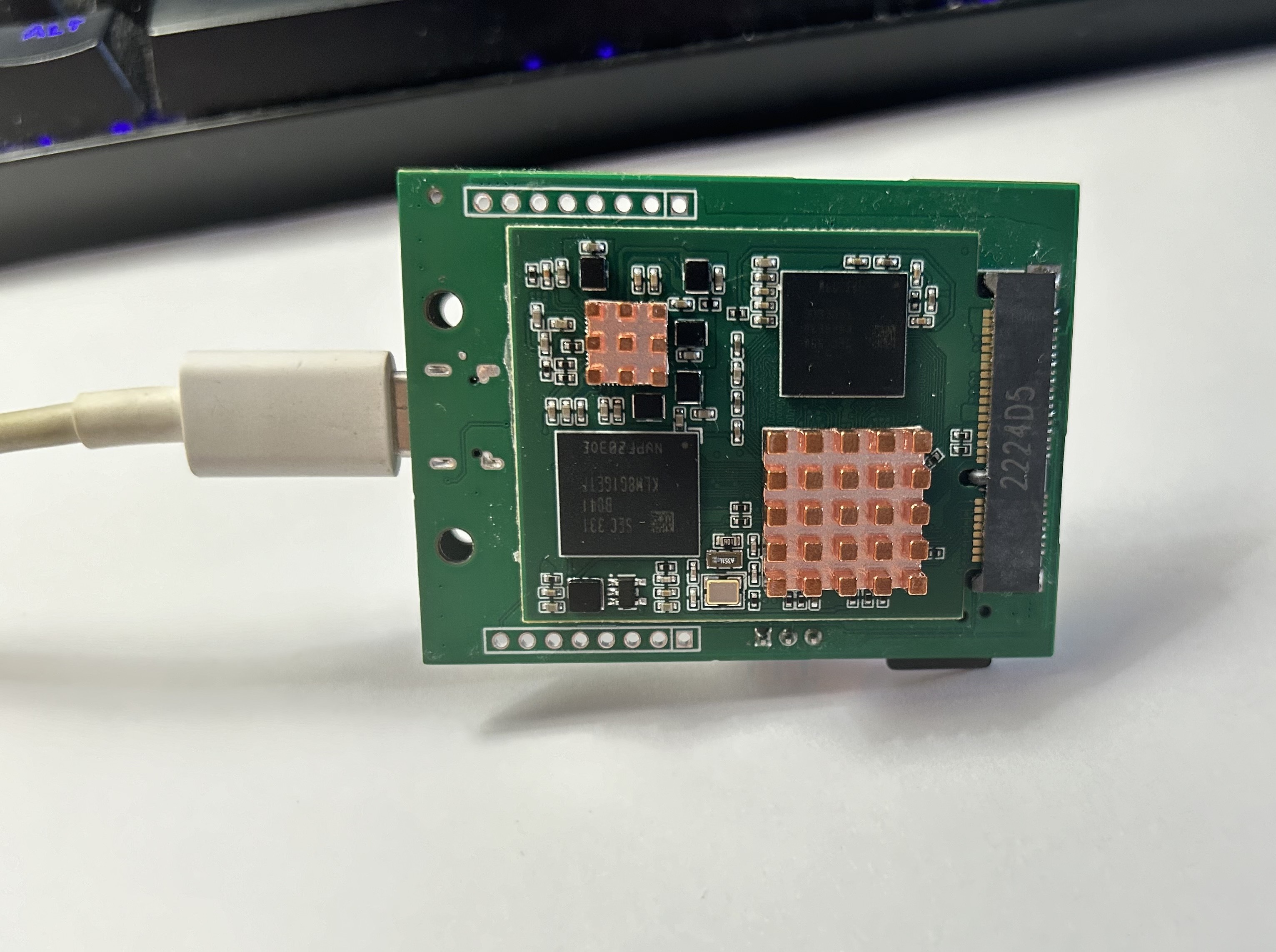
Core board basic composition: The main controller uses Allwinner H6 (1.8GHZ, V200-AI), memory uses Samsung K4E6E304E series LPDDR3 (2GB), plus Samsung EMMC (8GB) and power management chip AXP805, as well as related resistors, capacitors, and inductors. The core board uses a golden finger interface to connect with the peripheral board.
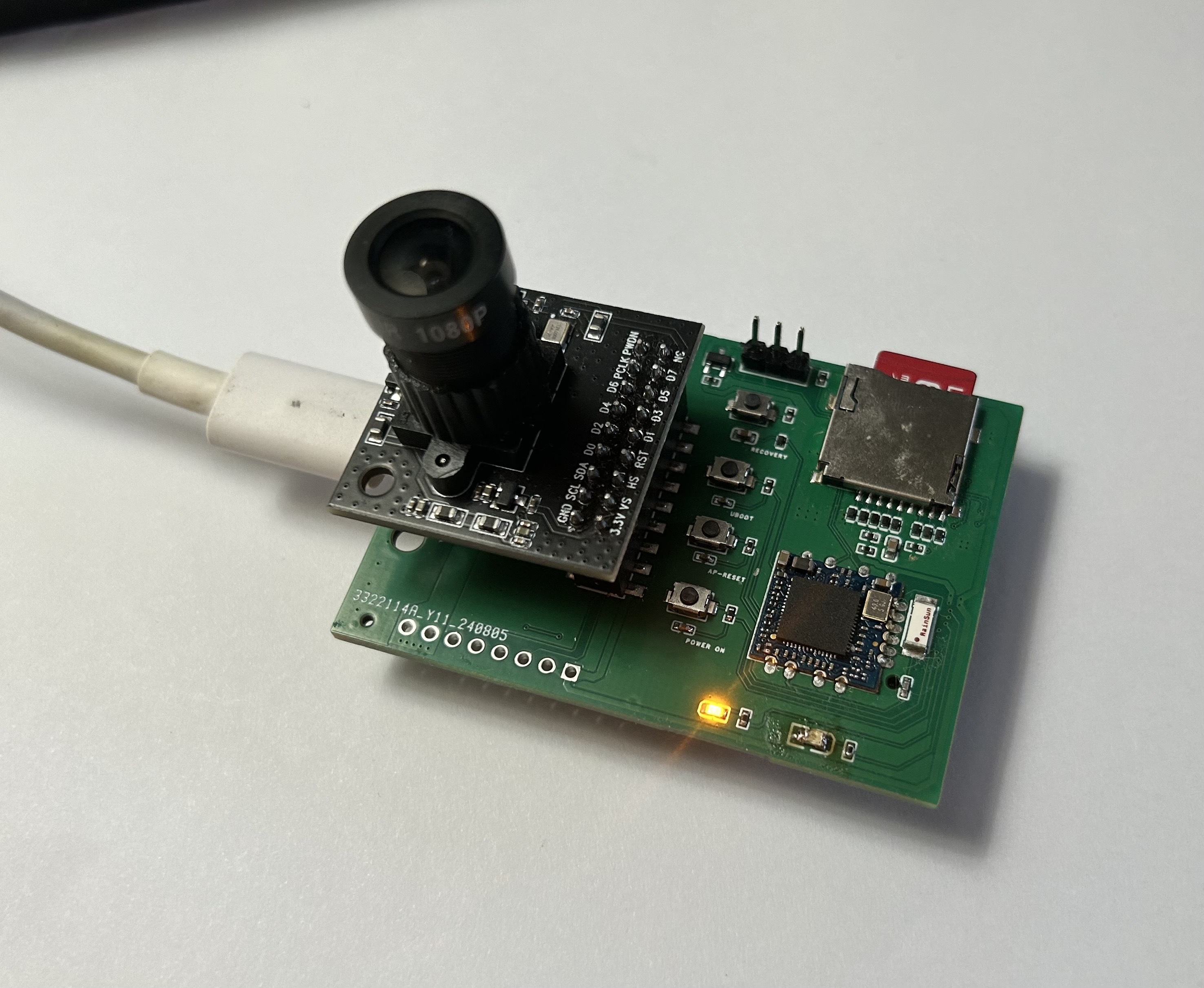
The basic composition of the peripheral board: USB TYPE-C power supply for the core board and peripheral board, related DC-DC step-down modules, several control buttons, wifi module (currently using RTL-8723BU, planning to switch to MT series later), TF card slot, OV5640 camera module. A TPU module (4TOPS) will be added later for AI computation acceleration.
What has been created? -------------------------- Product
By combining the core board and peripheral board, this project can serve as an edge AI processor, running a Linux Sunxi mainline system equipped with TPU neural network computation acceleration, used for deep learning and computer vision applications.
What functions have been implemented? -------------------------- Features
Currently, the core board has successfully and stably running Linux sunxi-5.10.75 system, with normal chip heating (compared to Orange Pi equivalent boards), normal DDR memory frequency, normal TF card system image loading, successful WiFi connection enabling SSH and other functions, and system interaction through serial port. Currently debugging the device tree part of the camera module, and camera test results are expected to come out soon.
What are the potential applications? -------------------- Applications
The applications are broad. As far as I know, there are few easy-to-use, easy-to-learn, and efficient-to-run edge AI modules in the current market that can run AI vision applications. Our board is mini-sized and powerful and will provide detailed technical documentation and guidance, making it convenient to deploy in smart homes, IoT, robotics, and other fields.
Schematic Design
Attached is the partial schematic of the core board. The complete schematic documentation can be found in the related attachments section.
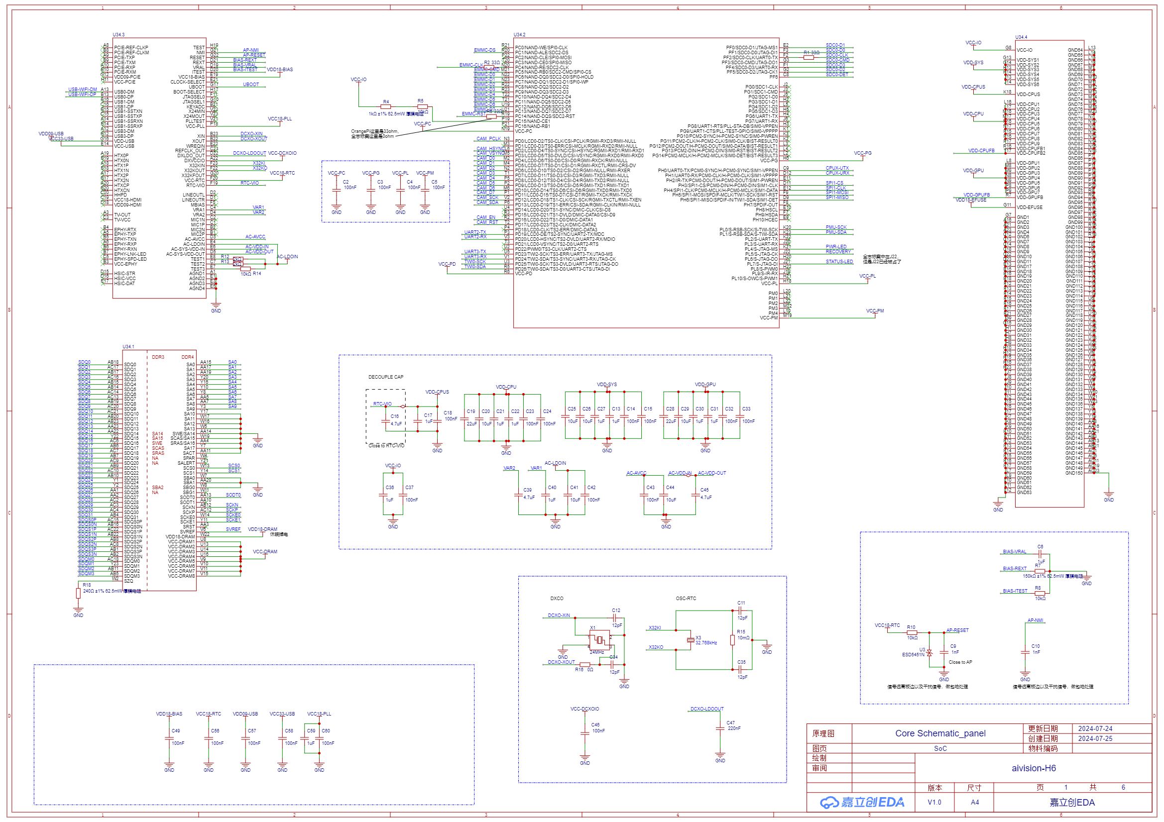
[1] Main Controller Chip Allwinner H6 SoC![SCH_Core Schematic_panel_1-SoC_2024-09-04.png]()
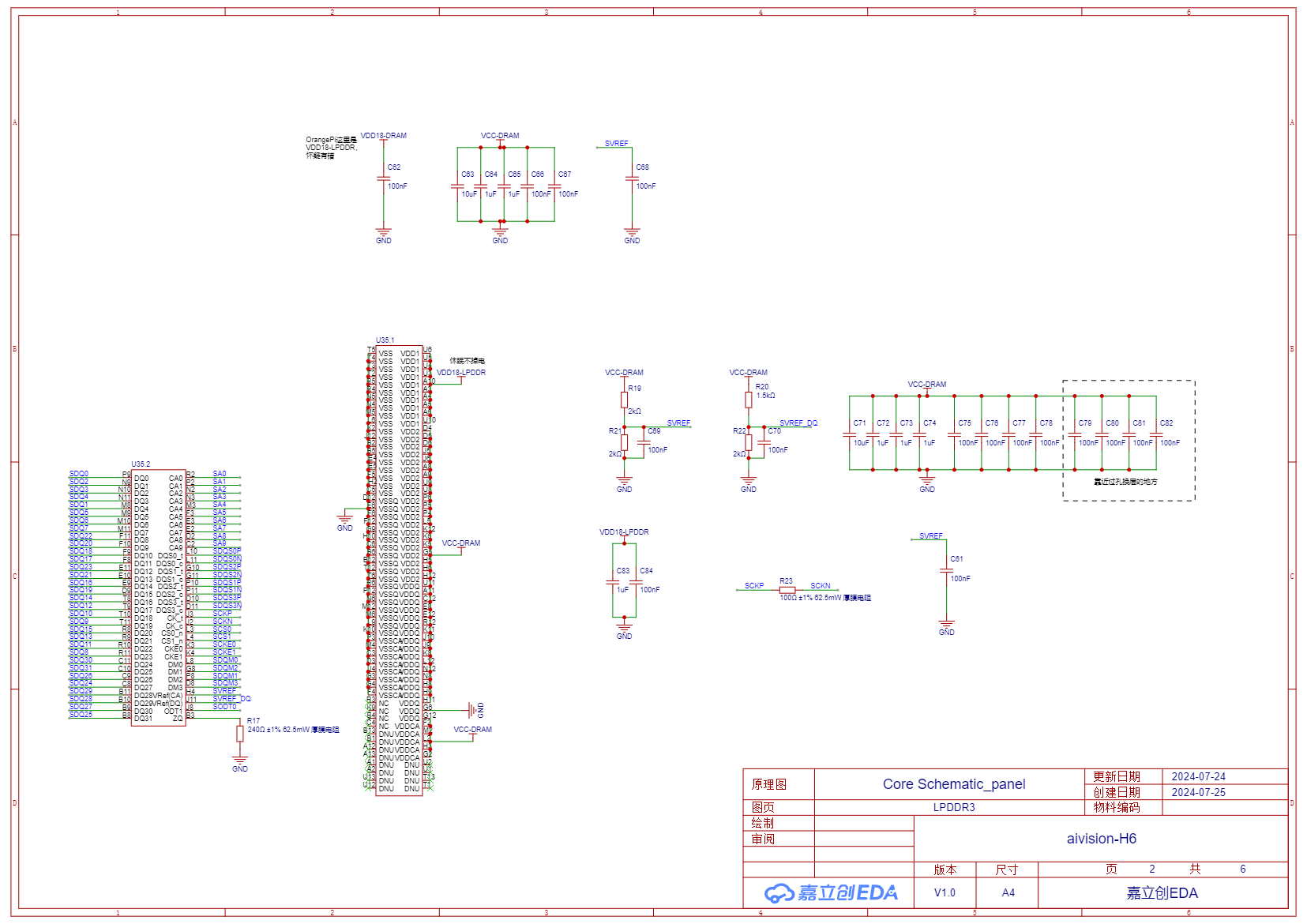
[2] Memory Chip LPDDR3
![SCH_Core Schematic_panel_2-LPDDR3_2024-09-04.png]()
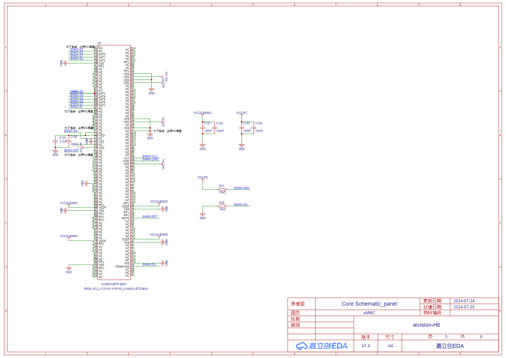
[3] Storage eMMC
![SCH_Core Schematic_panel_3-eMMC_2024-09-04.png]()
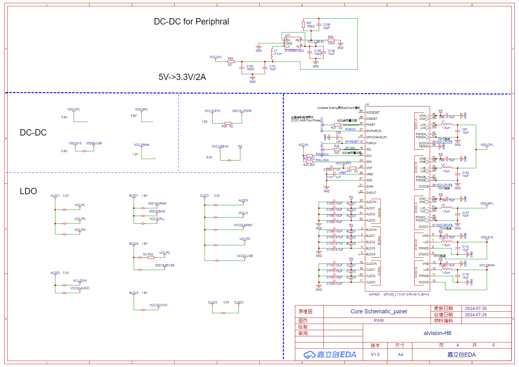
[4] Power Management Chip AXP805 and a DC-DC
![SCH_Core Schematic_panel_4-PWR_2024-09-04.png]()
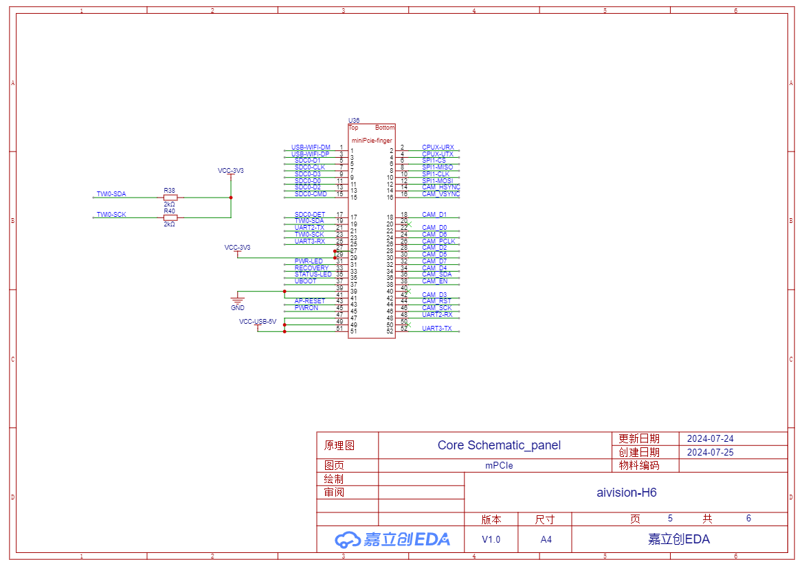
[5] Golden Finger Interface Definition
![SCH_Core Schematic_panel_5-mPCIe_2024-09-04.png]()
PCB Layout (Non-source files)
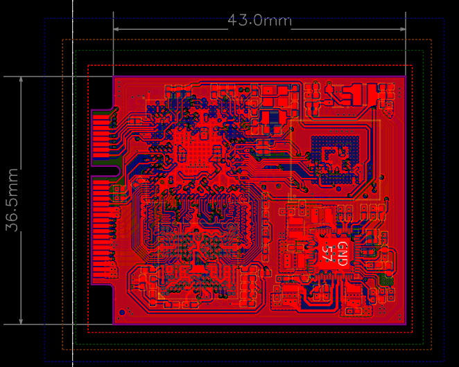
Top Layer of Core Board PCB
![core.png]()
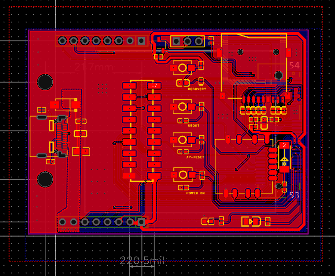
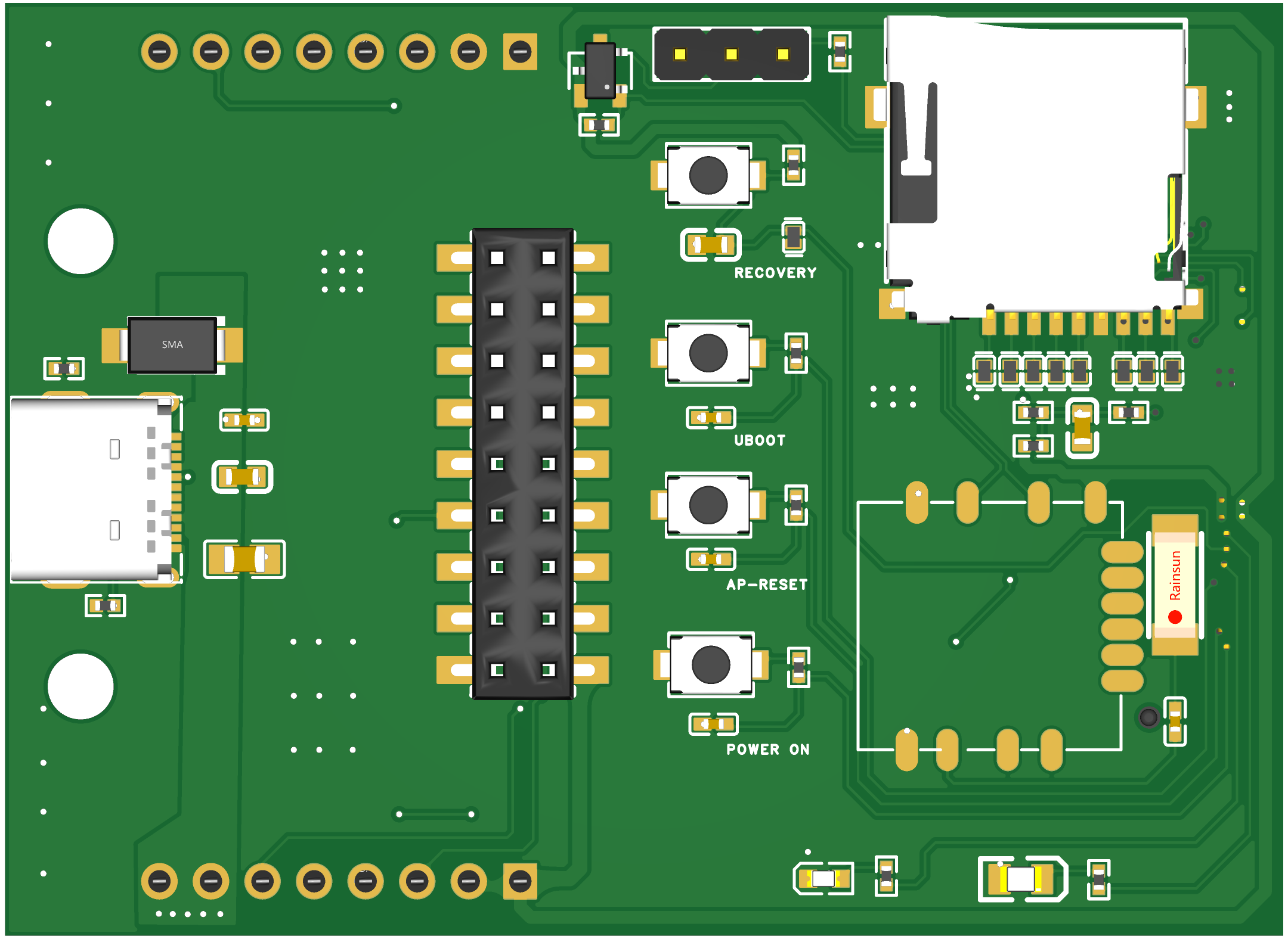
Peripheral Board PCB Top Layer
![base.png]()
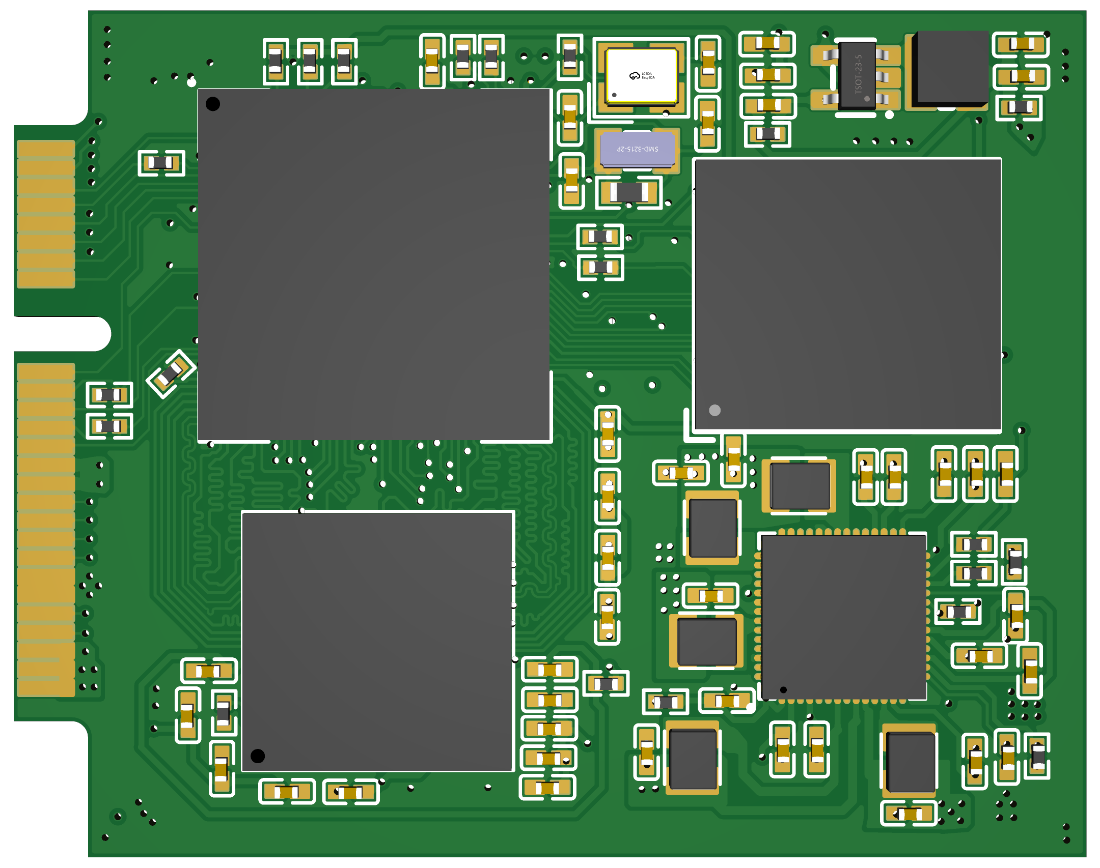
3D Rendering
Core board 3D rendering
![3D_Core PCB_panel_2024-09-04.png]()
Peripheral Board 3D rendering
![3D_Base PCB_panel_2024-09-04.png]()
Circuit Debugging Instructions
- After receiving the board, write the Linux system image file (the image file can be found in attachments) to the TF card and insert it into the TF card slot.
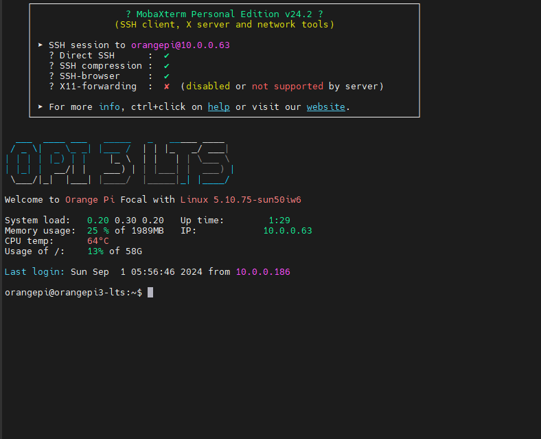
- Use a USB to TTL serial module. Connect one end of the serial module to the serial pin header interface on the peripheral board using three Dupont wires, and connect the other end (USB 2.0) to the PC. For Windows systems, use MobaXterm software, create a new serial session, and wait for the board to start.
- Press and hold the POWER ON button on the peripheral board until the red LED lights up. Release the button, and after a few seconds, the yellow LED will light up and the red LED will turn off, indicating successful board startup. At this time, the serial session should display the boot log output. Wait for the login prompt.
- Enter username "orangepi" (the system uses orangepi3-lts system) and password "orangepi" to enter the system command line interface.
- Use the command line interface under serial connection to set up the board's WiFi connection. After this, you can disconnect the serial connection and operate the board directly through an SSH wireless connection.
![image.png]()
Physical Product Display
Core Board:
![IMG_3072.png]()
Peripheral Board (core board is attached via Golden finger interface at back):
![IMG_3073.png]()
Contact Us and Technical Support
- Join us in Slack.
- Links to detailed board documentation will be added later, including AI vision models and applications developed based on the board.
- Purchase links for the board will be added later.
[相关附件]
Acknowledgements
The development of this project received help from many people. Thanks to Orange Pi for their Linux image documentation, and LogicWorld for sharing their materials。
aivision-H6
A Linux-based AI camera module that runs real-time deep-learning vision fully on-device for small robots and embedded projects.