Michael Yim
-
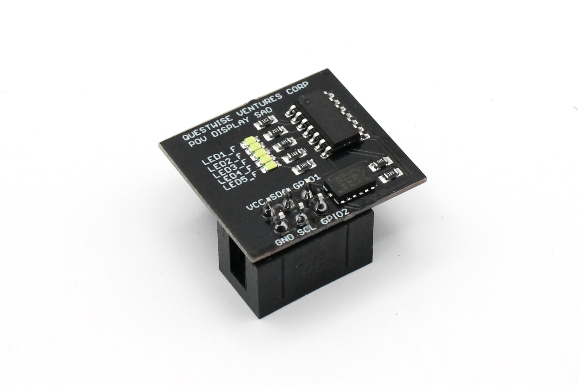
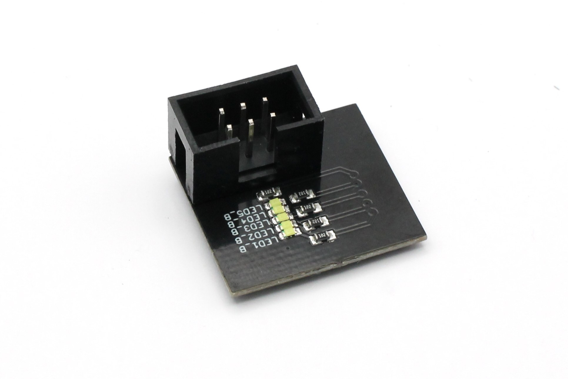
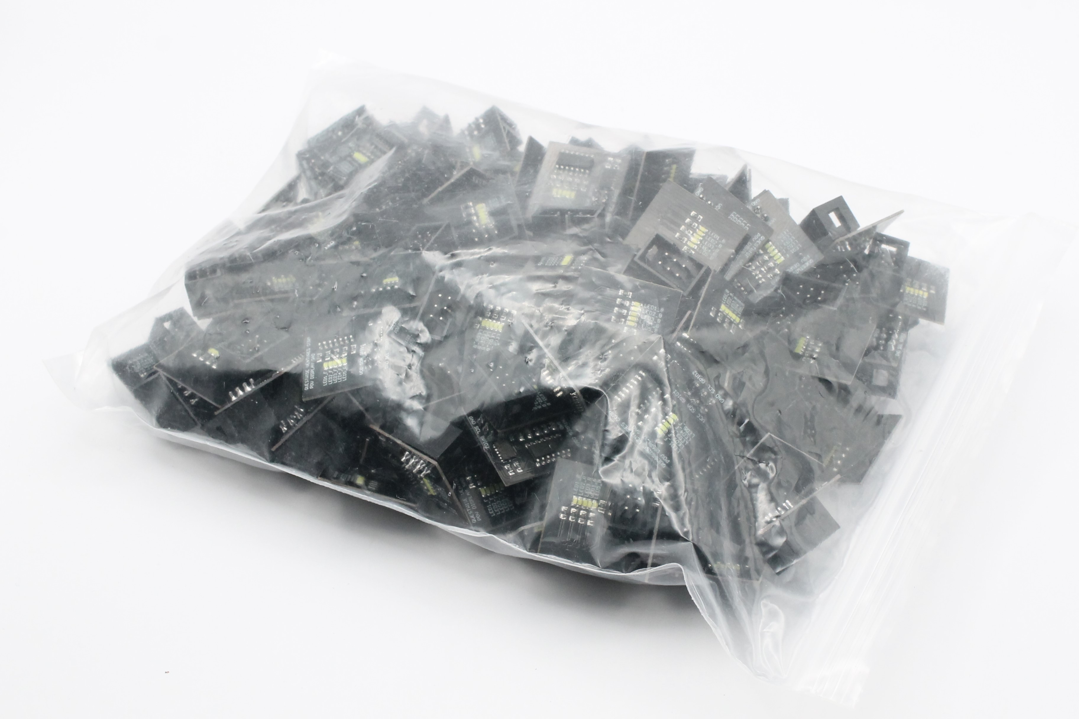
Final Product
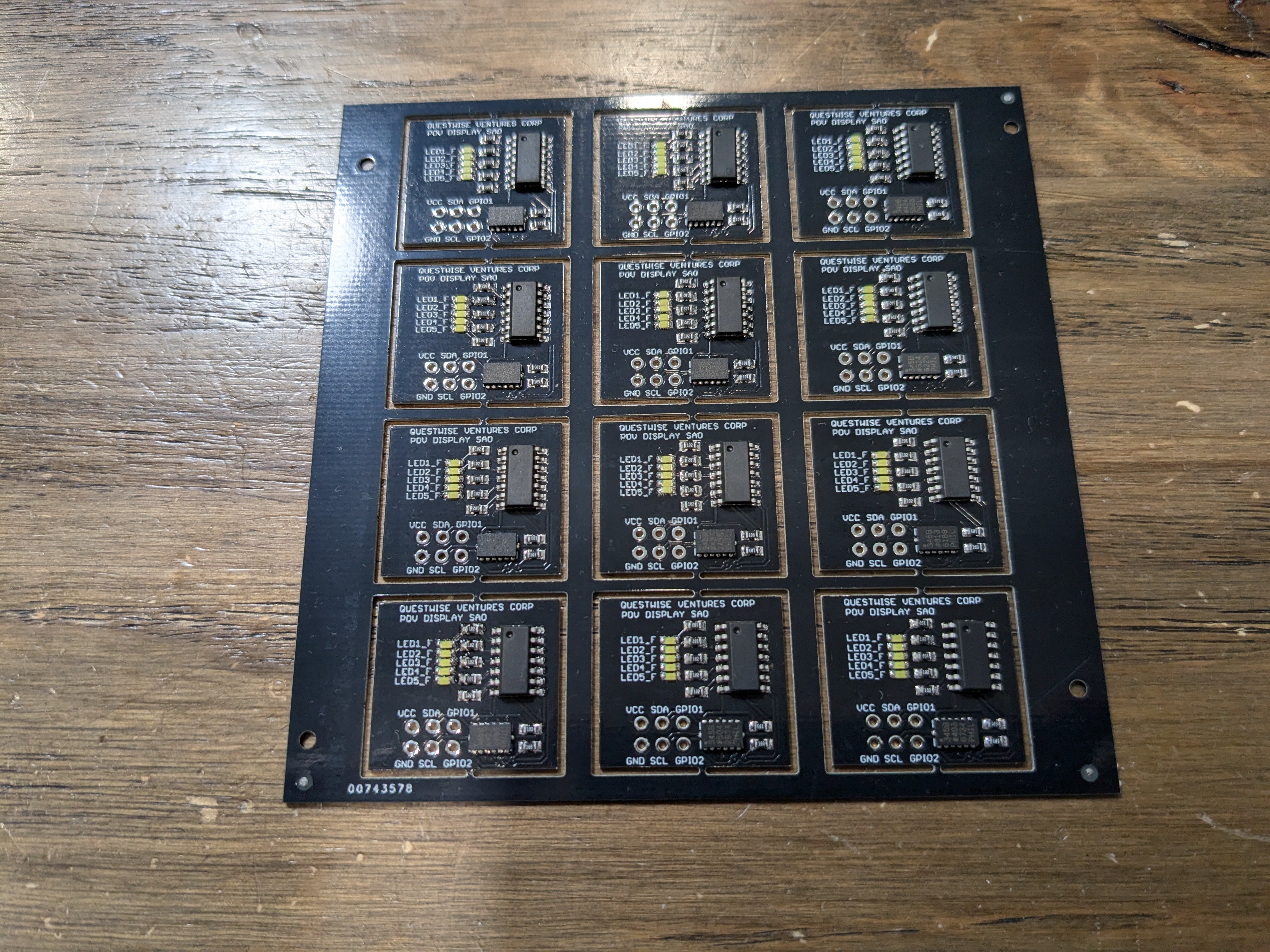
10/22/2024 at 07:15 • 0 commentsI'm pleased to share that the production run was a resounding success! Out of the entire batch, I now have 128 fully functional units, with only three ending up non-functional—an impressive outcome. The yield exceeded my initial expectations, likely thanks to the straightforward design and the precision setup of the LumenPnP pick-and-place machine.
Here are some pictures of the final product:
![]()
![]()
![]()
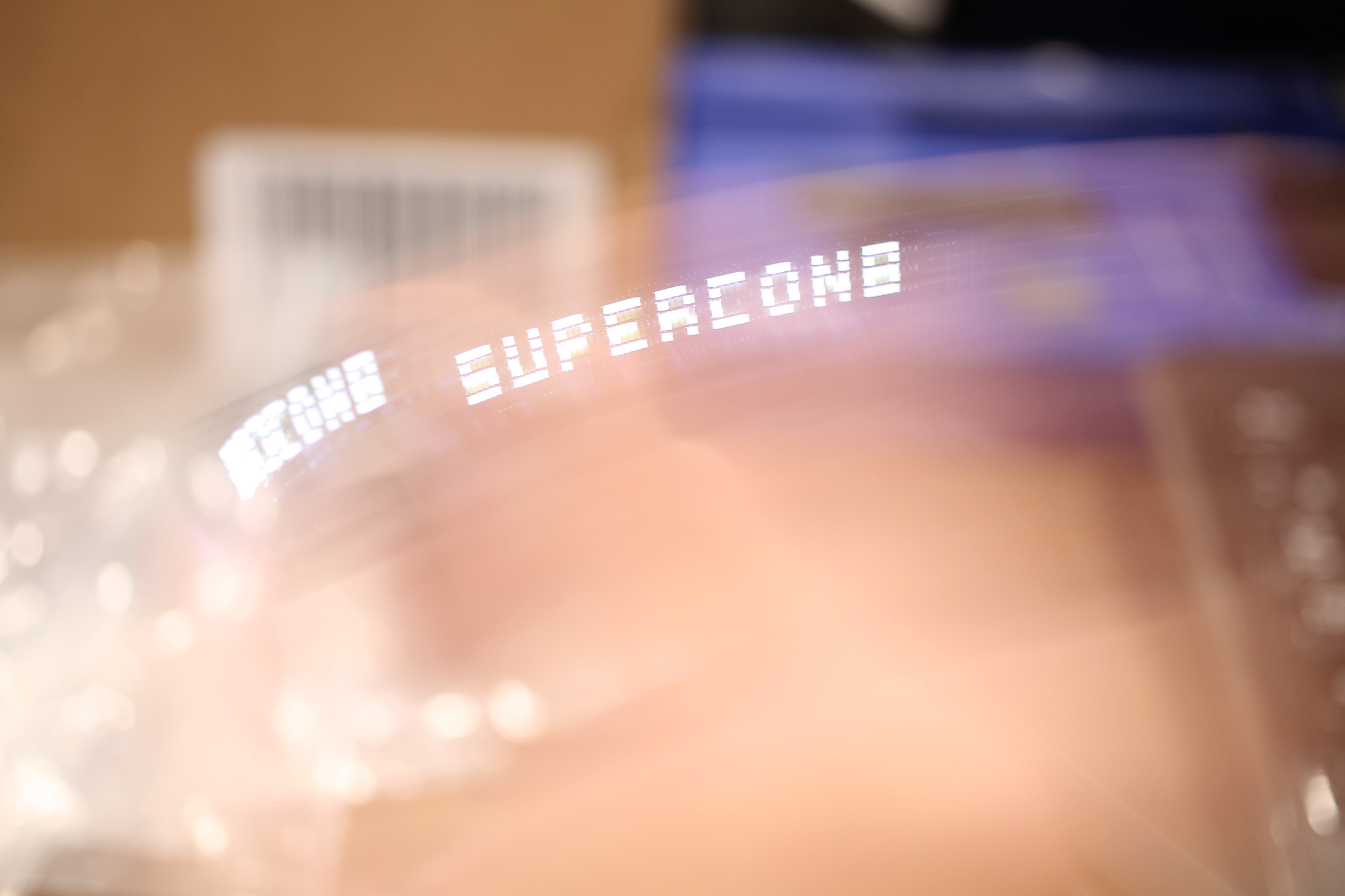
For those of you going to Supercon 2024, I'll be giving all these out for free! Hope to meet you there!
-
Testing Rig
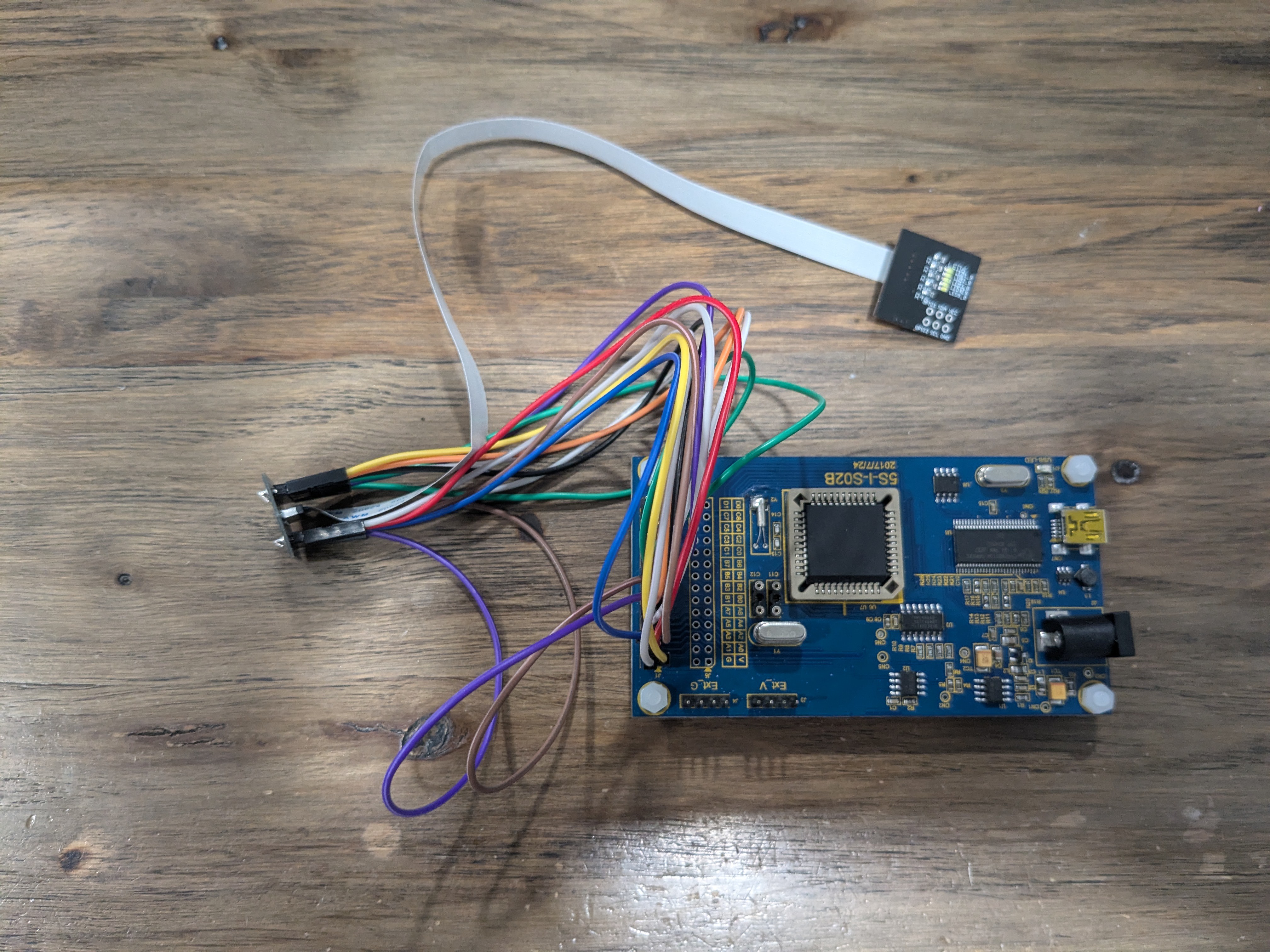
10/19/2024 at 19:54 • 0 commentsTo streamline the testing process, I put together a quick and simple testing rig using an Arduino Pro Micro, a tactile button, and a protoboard. This setup allows me to power the POV display and test its functionality efficiently.
![]()
Once I connect a USB cable to the Arduino Pro Micro, it provides power to the entire rig, including the POV display. The moment power is applied, I can wave the POV board back and forth to ensure both the front and back LEDs are functioning correctly. If the POV shows the message "SUPERCON8" correctly, it confirms that the basic hardware and display logic are working.
Next, I test the message change mode. This is initiated by double-tapping the POV board, which switches it into a specific mode that allows uploading a new message. This feature is handy, as it lets me reprogram the message directly without disconnecting or resetting the board every time.
Finally, I press the tactile button connected to the Arduino Pro Micro. This button triggers an interrupt routine on the microcontroller, which immediately uploads a new message—in this case, "HELLO"—to the POV display.
-
Production Run!
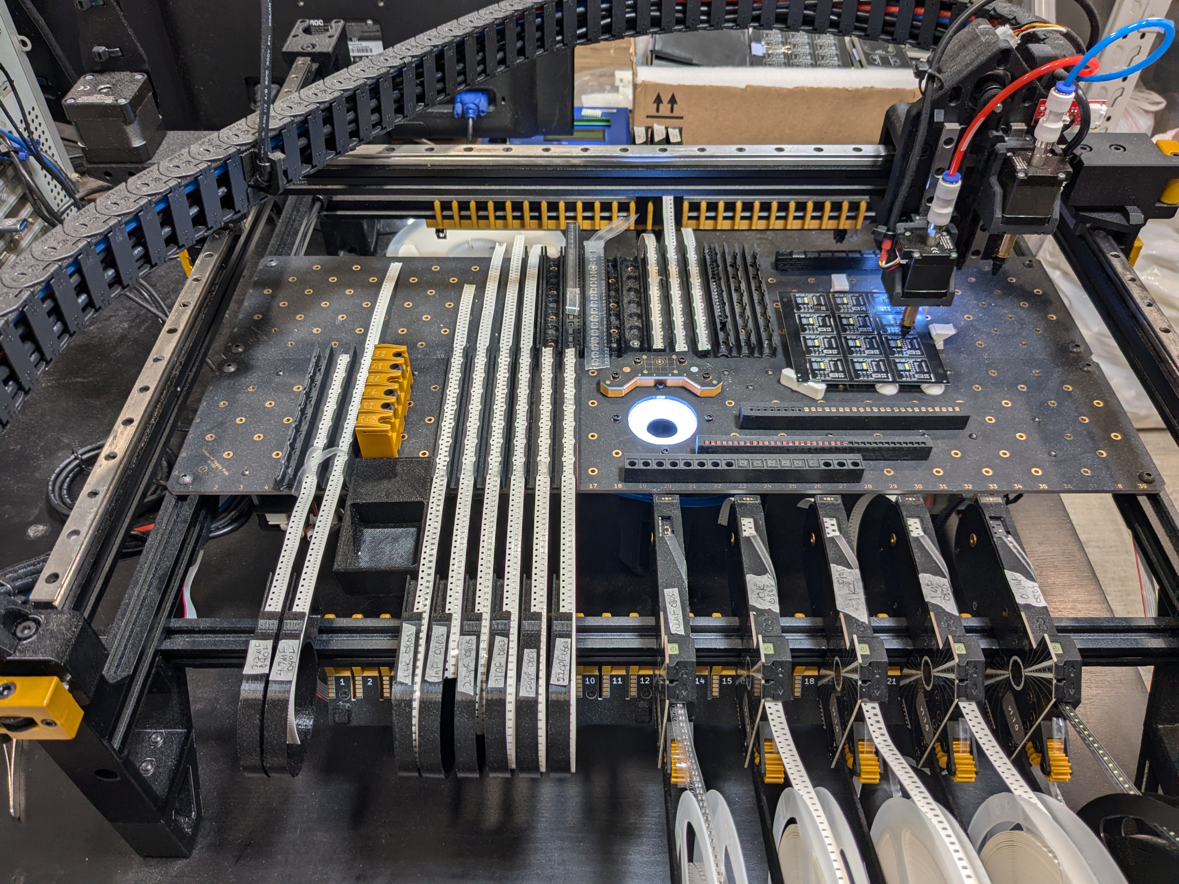
10/17/2024 at 23:55 • 0 commentsThe PCBs and components have arrived, and everything is looking great! I’ve completed the first panel, which holds a dozen of the POV displays, and I’m really pleased with how they turned out. My goal is to manufacture at least 100 fully functional units. I have enough parts on hand to build around 120 units, but I’m being realistic—my yield likely won’t be 100%, so there may be a few casualties along the way.
I plan to keep building until I completely exhaust my supply of parts. But once I hit that 100 unit milestone, I’ll consider the project a success and officially wrap it up. It’s been quite a journey bringing this idea to life, and seeing the displays assembled and functioning feels incredibly rewarding. I can’t wait to see how they perform when they’re all in the hands of users!
![]()
![]()
![]()
-
Supported ASCII Characters
10/17/2024 at 09:32 • 0 commentsGiven the limited memory available, I opted to support only a small subset of ASCII characters to ensure efficient performance. This selective approach allows me to maximize the display's functionality while keeping memory usage low. Below is the list of supported characters:
- A-Z (caps only)
- 0-9
- Space
- !
- "
- #
- %
- '
- (
- )
- *
- +
- ,
- -
- .
- /
- :
- <
- =
- >
By focusing on essential characters, the system can still convey meaningful information without overwhelming the memory. This subset covers common letters, numbers, and symbols frequently used in typical messages, ensuring the POV display remains useful and practical for various applications. If needed, additional characters could be supported later by optimizing other parts of the code or by swapping in new character sets dynamically via I2C.
-
Default POV Message
10/17/2024 at 04:26 • 0 commentsInstead of requiring users to upload a message before testing the POV display, I aimed to provide a default message right out of the box for an easy, hassle-free experience. This way, users can interact with the display immediately without needing to figure out the upload instructions. To achieve this, I modified the state machine and configured the accelerometer to detect a double-tap event. At startup, the POV display now shows the message "SUPERCON8" as the default message. I find this to be fitting. If the user double-taps the POV SAO board, it switches to a mode that waits for an I2C upload of a new message. Once the new message is uploaded, the display switches back to show the updated message.
Final State Machine:
- State 0 – Initialize POV Display
- State 1 – Display POV Message
- State 2 – Wait for Message via I2C
- State 3 – Retrieve Message from I2C
-
PFC232 as an I2C Slave
10/07/2024 at 22:09 • 0 commentsTo enable user customization of the POV message, my approach is to allow the user to write the message in ASCII characters and send it to the PFC232 microcontroller via I2C. In this setup, the PFC232 will function as an I2C slave, which is a bit unconventional, as microcontrollers typically act as I2C masters, such as when reading data from the ADXL345 sensor. In my case, the microcontroller must act as BOTH a master (for reading the ADXL345), and also a slave for handling the upload of I2C messages from the user.
The Padauk FPPA IDE has a very nice tool to generate boilerplate code for I2C slave, which can handle multiple-byte buffer write and reads.
void    I2C_Slave (void)
{
    $ I2C_SCL_Slave    In;
    $ I2C_SDA_Slave    In;

    .delay    99;        //    Wait for master ready


    addr$1    =    0;    //    at the sample code, only access one byte of address.

Stop:

        .wait1    I2C_SCL_Slave
        if (! I2C_SDA_Slave)    goto Stop;

High:    if (! I2C_SCL_Slave)    goto Stop;
        if (I2C_SDA_Slave)        goto High;

Start:    if (! I2C_SCL_Slave)    goto Chk_Ax;
        if (! I2C_SDA_Slave)    goto Start;
        goto High;

Chk_Ax:
    BYTE    count    =    DEVICE_LEN;
    A    =    I2C_SLAVE_DEVICE;
    do
    {
        sl    A;
        .wait1    I2C_SCL_Slave
        if (I2C_SDA_Slave)
        {
            if (! CF) goto Stop;
            while (1)
            {
                if (! I2C_SCL_Slave)    break;
                if (! I2C_SDA_Slave)    goto Start;
            }
        }
        else
        {
            if (CF) goto Stop;
            while (1)
            {
                if (! I2C_SCL_Slave)    break;
                if (I2C_SDA_Slave)        goto Stop;
            }
        }
    } while (--count);

    if (DEVICE_LEN != 7)
    {
        BYTE    hi_adr    =    0;
        A    =    7 - DEVICE_LEN;
        do
        {
            .wait1    I2C_SCL_Slave
            if (I2C_SDA_Slave)
            {
                CF    =    1;
                slc    hi_adr;
                while (1)
                {
                    if (! I2C_SCL_Slave)    break;
                    if (! I2C_SDA_Slave)    goto Start;
                }
            }
            else
            {
                sl    hi_adr;
                while (1)
                {
                    if (! I2C_SCL_Slave)    break;
                    if (I2C_SDA_Slave)        goto Stop;
                }
            }
        } while (--A);
    }

    .wait1    I2C_SCL_Slave

    BYTE    data;

    if (I2C_SDA_Slave)
    {    //    Read
        while (1)
        {
            if (! I2C_SCL_Slave)    break;
            if (! I2C_SDA_Slave)    goto Start;
        }

        $ I2C_SDA_Slave        Out, Low;
        .wait1    I2C_SCL_Slave

Send:    count    =    8;
        data    =    ~ *addr;
        addr$0++;

        do
        {
            .wait0    I2C_SCL_Slave
            sl        data;
        #if    _SYS(OP:SWAPC IO.N)
            swapc    _PXC(I2C_SDA_Slave);
        #else
            if (!CF)    $ I2C_SDA_Slave    In;
            if (CF)        $ I2C_SDA_Slave    Out;
        #endif
            $ I2C_SDA_Slave    Low;
            .wait1    I2C_SCL_Slave
        } while (--count);

        .wait0    I2C_SCL_Slave
        $ I2C_SDA_Slave        In;

        .wait1    I2C_SCL_Slave

Watch:    if (I2C_SDA_Slave)    goto Stop;
        if (I2C_SCL_Slave)    goto Watch;
        goto Send;
    }
    //    Write
    while (1)
    {
        if (! I2C_SCL_Slave)    break;
        if (I2C_SDA_Slave)        goto Stop;
    }

    $ I2C_SDA_Slave        Out, Low;
    .wait1    I2C_SCL_Slave

    addr$1.0    =    1;
    while (1)
    {
        .wait0    I2C_SCL_Slave
        $ I2C_SDA_Slave        In;

        count    =    8;

        do
        {
            .wait1    I2C_SCL_Slave
            if (I2C_SDA_Slave)
            {
                CF    =    1;
                slc    data;
                while (1)
                {
                    if (! I2C_SCL_Slave)    break;
                    if (! I2C_SDA_Slave)    goto Start;
                }
            }
            else
            {
                sl    data;
                while (1)
                {
                    if (! I2C_SCL_Slave)    break;
                    if (I2C_SDA_Slave)        goto Stop;
                }
            }
        } while (--count);

        $ I2C_SDA_Slave        Out, Low;
        .wait1    I2C_SCL_Slave


        if (addr$1.0)        addr    =    data;
        else
        {
            *addr    =    data;
            addr$0++;

            //Set Message Transfered Flag
            MsgFlag = 1;
        }
    }
}
Initially, I planned to allow users to upload custom messages on the fly, but it turned out to be more challenging than expected with my current hardware setup. The issue arose because both the master and slave I2C devices shared the same SCL and SDA lines, leading to conflicts when they attempted I2C transactions simultaneously. Since the Padauk environment doesn't natively support MUTEX operations, managing these conflicts became difficult.
To resolve this, I simplified the design. Now, the user can only upload a message at the start of the operation. Once the message is uploaded, the LEDs will blink, and the POV display will show the message. No new messages can be uploaded during operation. The only way to change the message is to restart the POV display and upload a new one.
This made the software implementation much easier. I used a simple state machine in which State 0 waits for the user to upload the message (in I2C Slave mode). Once the message is uploaded, it transitions into State 1, where the I2C Master takes over the SCL and SDA lines. In this state, the ADXL345 is initialized and configured to the right settings. Then comes State 2, where it polls the ADXL345 and synchronizes the scanning of the virtual columns of the POV display.
I also encountered a RAM limitation issue. The PFC232 microcontroller is quite affordable, but it only comes with a small 128-byte data RAM, which is shared between the two FPPA units. Initially, I wanted the POV display to support up to 20 characters, but I discovered that 12 characters is the actual limit. In hindsight, 12 characters turned out to be a practical limit as well. If the message is too long, the user would need to wave the display faster and over a greater distance. Beyond a certain point, the message becomes too long to display properly, given the user's realistic waving speed.
With all these challenges finally resolved, including addressing the PCB's cosmetic issues, I moved forward and sent the design for a new PCB production cycle. Now, it's just a matter of waiting for the new PCBs and parts to arrive so I can begin the process of mass manufacturing.
In the meantime, I'll be focusing on fine-tuning my LumenPnP Pick and Place machine to get it ready for this production run. It's essential to ensure the machine is calibrated precisely for this particular job, as it will be handling small components with high accuracy and speed.
-
Syncing Hand Movements with LED Blinking
10/07/2024 at 21:35 • 0 commentsThe most challenging aspect of this project is processing the accelerometer data to accurately synchronize the scanning of the display’s virtual columns. This ensures that the correct LEDs turn on and off at the precise moments during hand movements. It also makes it even more difficult by using Padauk's Mini-C, which is a stripped down primitive C-like language.
Since the language lacks support for floating point numbers and signed integers, working with real-world units like meters per second would be quite cumbersome. However, for this project, I believe I can bypass this limitation by using the raw accelerometer values directly. Instead of converting them into precise physical measurements, I’ll simply rely on the raw data to determine the direction of movement and relative magnitude. This should be sufficient for synchronizing the scanning of the display's virtual columns, as the project doesn’t require exact speed values—just enough information to detect motion and adjust the LED timing accordingly.
For the purposes of this project, I will just be using the x axis of the accelerometer data.
First, I grabbed the raw data from the accelerometer with the following code:
//Get x_l
I2C_Address    =    0x32;
I2C_Read_Byte();
x_l = A;

//Get x_h
I2C_Address    =    0x33;
I2C_Read_Byte();
x_h = A;

//Combined x
x = x_l | (x_h << 8);
This reads the HIGH byte and the LOW byte from the ADXL345, then combines them into a 16-bit WORD.
Since the data is represented with 2's complement numbers, I extracted the sign and magnitude separately using the following code:
// Get x_acceleration_sign and apply two's complement if necessary
 if (x & 0x8000) { // If MSB is 1, it's negative
     x = (~x + 1) & 0xFFFF; // Apply two's complement
     x_acceleration_sign = 1; // Set sign as negative
 } else {
     x_acceleration_sign = 0; // Set sign as positive
 }
In my initial approach, I tried using only the x_sign of the accelerometer data to determine the direction of hand waving. The idea was that a positive x_sign would indicate movement in one direction, while a negative value would signal the opposite. However, this method didn’t work as expected.
The issue arose during deceleration—when the user was still waving in the positive direction but began to slow down, the x_sign would flip to negative. This caused the display to misinterpret the motion, as it couldn't distinguish between slowing down and an actual change in direction. As a result, the display would sometimes show inverted characters. It took me some time to realize that deceleration was the problem.
After lots of trial and error into what works and what doesn't, I ended up with a relatively simple solution. I first check if there is any movement. This is done using the built-in ADXL interrupts.
integrating the acceleration number into a velocity, even though my approach isn't very accurate:
//Get int_source
 I2C_Address = 0x30;
 I2C_Read_Byte();
 int_source = A;

 //If there is movement
 if (int_source.4 == 1) { // Handle negative acceleration (decrease velocity)
 if (x_acceleration_sign == 1) {
     if (x_velocity >= x) {
     x_velocity -= x; // Subtract from velocity
     } else {
         x_velocity = x - x_velocity; // Handle negative velocity (use two's complement)
         x_velocity_sign = 1; // Set sign as negative
     }
 }

 // Handle positive acceleration (increase velocity)
 else {
     if (x_velocity_sign == 1) { // If the velocity is currently negative
         if (x_velocity >= x) {
             x_velocity -= x; // Reduce the negative velocity magnitude
         } else {
             x_velocity = x - x_velocity; // Positive velocity takes over
             x_velocity_sign = 0; // Reset sign to positive
         }
     } else {
         x_velocity += x; // Positive acceleration, increase velocity
         }
     }
 }

 //No Movement
 else{
     x_velocity = 0;
 }
I then use the sign of the velocity to determine the direction. The following code to increments and decrements the virtual columns of the front and back LEDs and then use that to toggle on and off of the LEDs.
  //Right
   if(x_velocity_sign == 1){
      IncrementCol_F();
      DecrementCol_B();
  }

  //Left
  else {
      DecrementCol_F();
      IncrementCol_B();
  }

    //Display Column
    DisplayColumn();


      //Column Delay
      .delay 100;


        //Briefly Turn off ALL leds
      PA.7 = 0;
      PA.6 = 0;
      PA.5 = 0;
      PB.7 = 0;
      PB.4 = 0;

      PA.0 = 0;
      PA.4 = 0;
      PA.3 = 0;
      PB.3 = 0;
      PB.1 = 0;
This yielded a satisfactory solution. As you can see in the pictures and video, the POV display finally works!!
![]()
-
Padauk 5S-I-S02B ICE Emulation
10/05/2024 at 22:44 • 0 commentsUnlike the Padauk PMS150C microcontroller, which you can only upload a program once, the PFC232 supports multiple rewrites. However, since my current workflow does not allow me to do onboard programming, it would be a hassle to de-solder the chip to do reprogramming each time I change the code. So I used Padauk's ICE 5S-I-S02B hardware emulator. It doesn't support my particular PFC232 IC, so instead I emulated it using PMS132B settings.
![]()
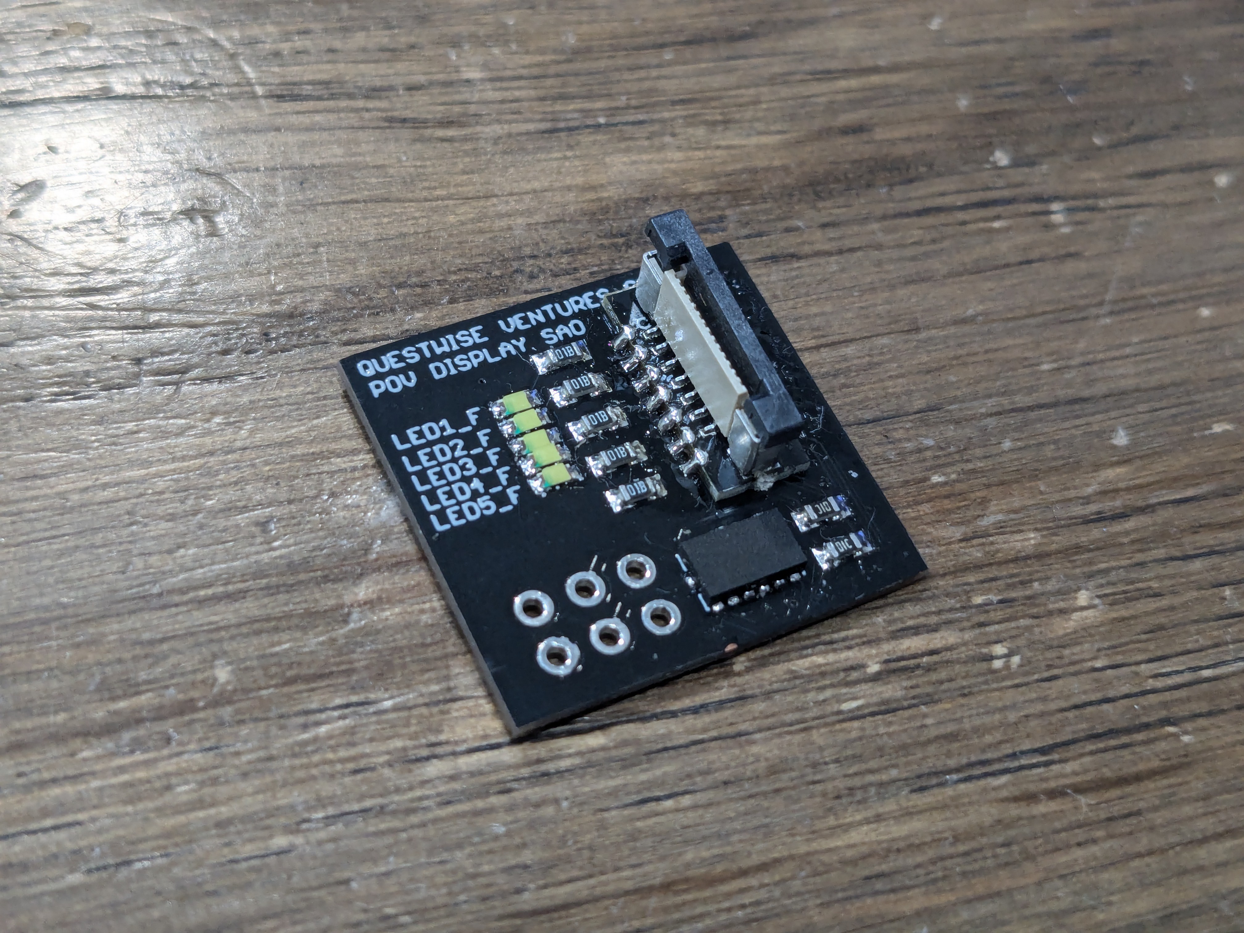
I also made a custom FPC connector board with the same PFC232 footprint that replaces the original IC so I can connect the POV board to the emulator:
![]()
After doing this, I wrote Padauk Mini-C code to test each part of the hardware individually. I was able to verify that each piece of the hardware worked. The LEDs all lighted up and I was able to read from the ADXL345 accelerometer, a very good sign things are going well.
-
Custom PCB Arrived
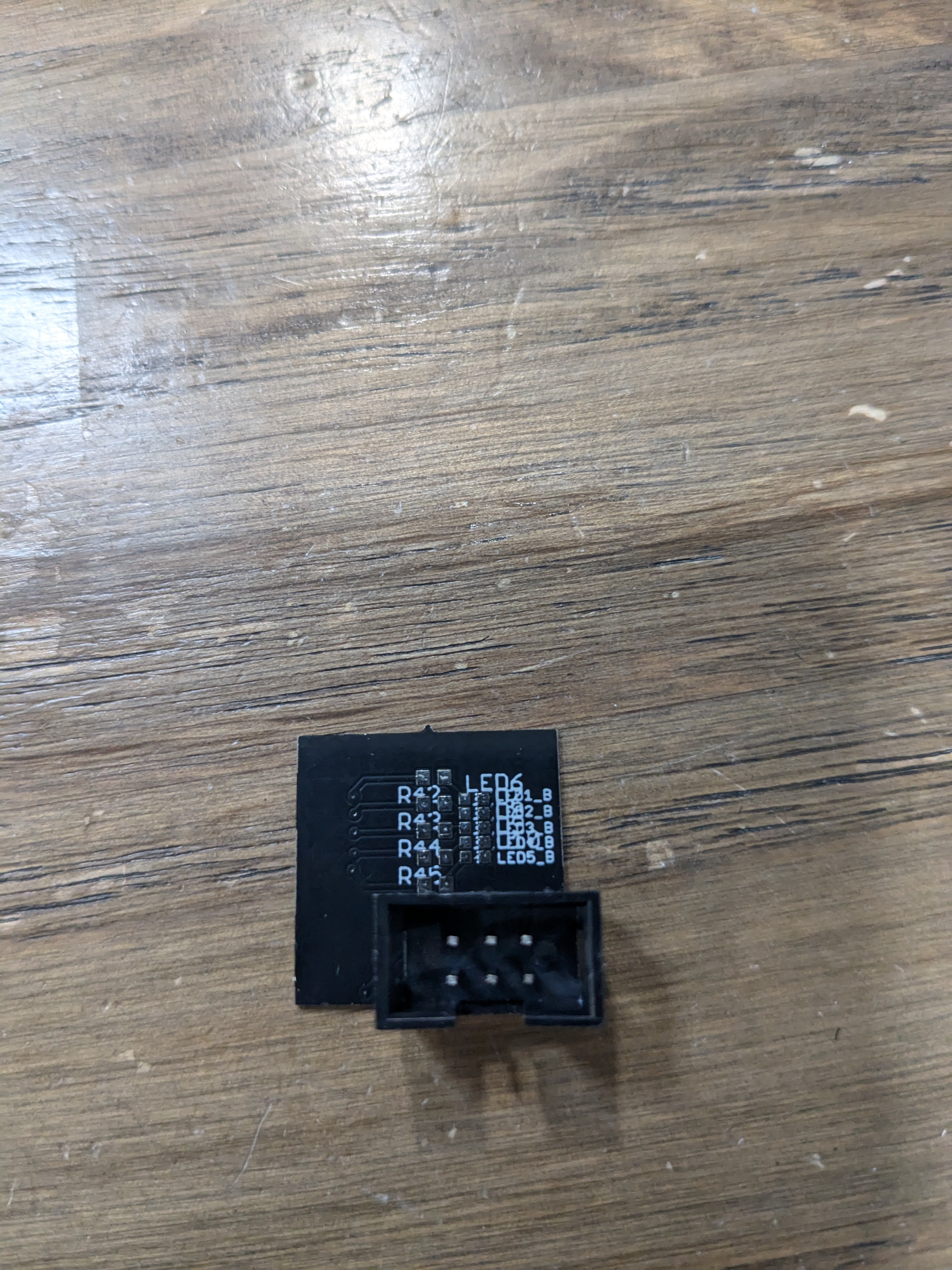
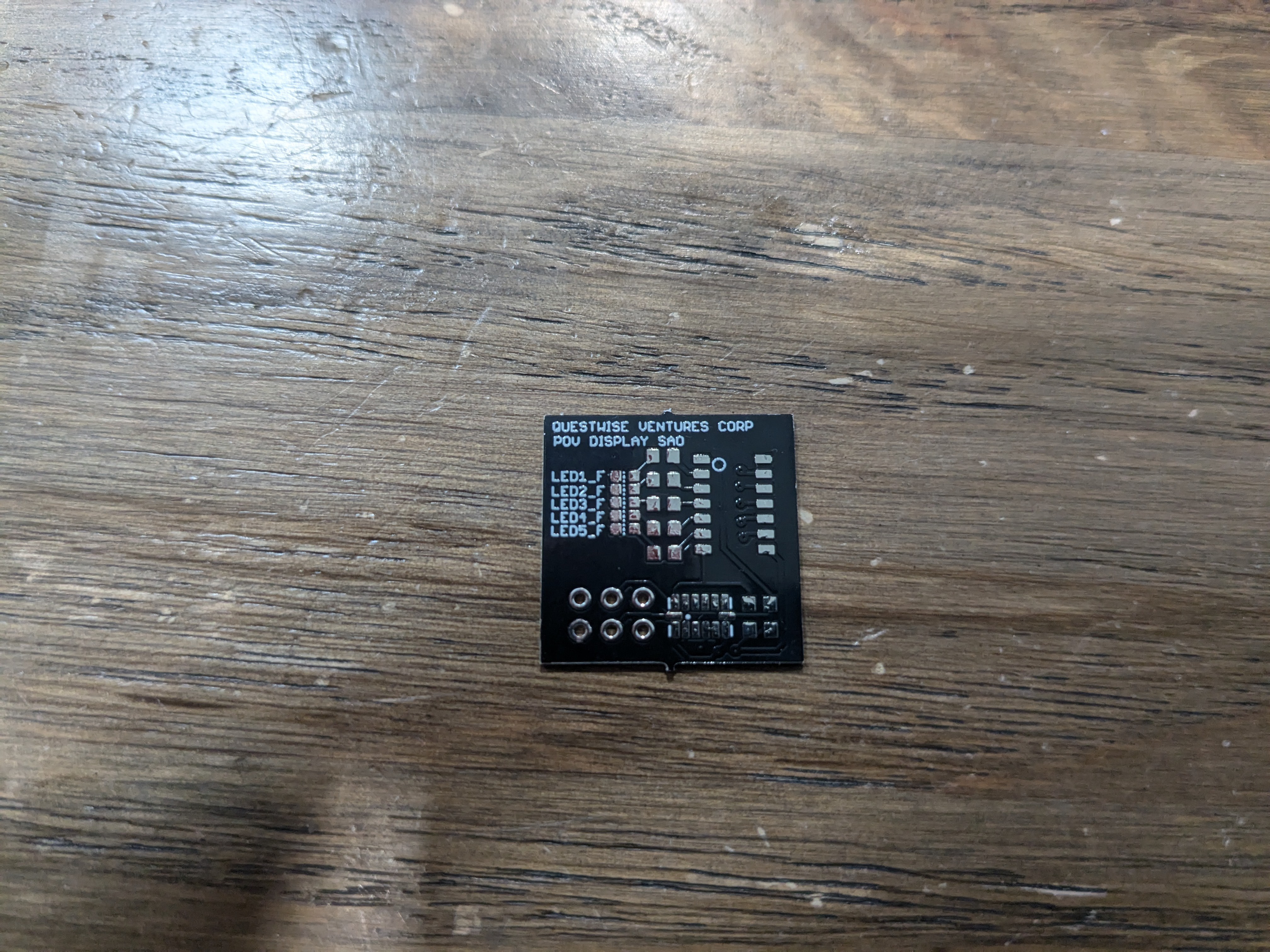
10/04/2024 at 23:27 • 0 commentsAs soon as the custom PCB came back, I immediately noticed that I've made a few small mistakes:
- The back silkscreen LED names got messed up
- I should have made the SAO pin labeling on the top silkscreen instead of bottom as having it on the bottom would be covered by the header itself.
![]()
![]()
Not to worry, these mistakes are only cosmetic and don't mean game-over yet. Hopefully it can still help me see if my concept works or not.
If I am to mass produce these for the Hackaday Supercon 2024, I still have time for ONE more iteration if I work hard. But that iteration would have to be final final, otherwise I'm not going to make it.
-
2nd Prototype - Custom PCB
10/04/2024 at 23:08 • 0 commentsAlthough my first attempt had its issues, I suspected that the main problem lay with the size of the LEDs. The larger LEDs required the user to wave their hand over a considerable distance just to display a simple message, which made the output less clear and harder to control. This led me to the conclusion that using smaller LEDs could improve the precision of the display.
Due to time constraints, I just had to run with the idea and try creating a custom PCB with 0603 SMT LEDs, which are significantly smaller. This should allow for more compact and sharper visuals, as well as shorter hand movements to display clear messages.
In this version, instead of being controlled by an Arduino Pro Micro, I will use a Padauk PFC232 microcontroller. This microcontroller is inexpensive and a cousin to the famous cheap PMS150C. I particularly picked the PFC232 because it has 2 FPPAs (kinda like cores that run in parallel). One FPPA would handle the main logic and be the I2C host and interface with the ADXL345. The other FPPA would be the I2C Slave to handle the user writing a new message to the display.
I also needed 10 GPIOs to control and front and back LEDs, and another 2 GPIOs to use with I2C. The PFC232 SOP14 version fits my needs perfectly.
Persistence of Vision POV Display SAO
Accelerometer-based Hand-waved POV display with front and back LEDs, creating a 5 pixel x 12 char display. Message customizable via I2C.