Close
0%
0%

SPINC - DIY Automatic NiMH Charger

Open-Source Self-Loading Battery Charger Using the RP2040

Similar projects worth following
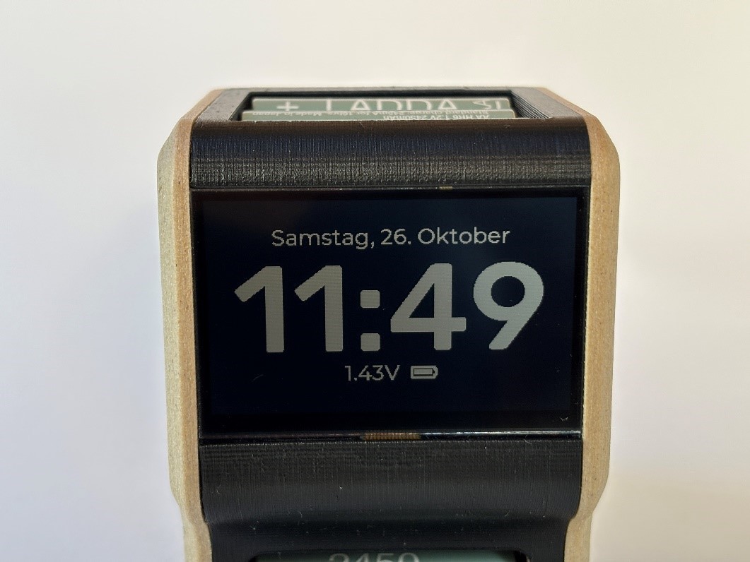
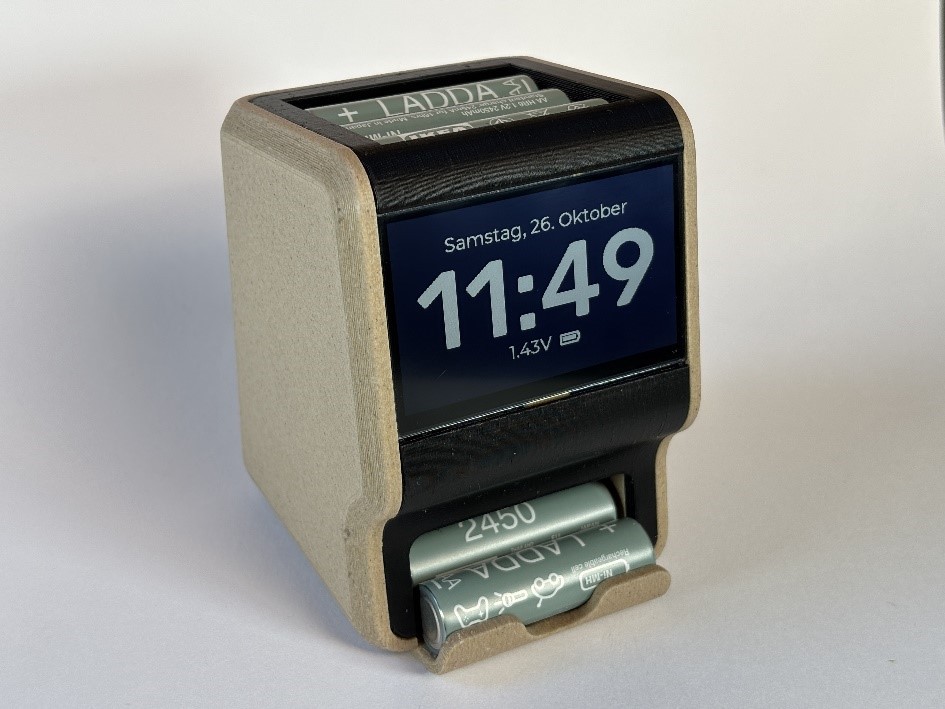
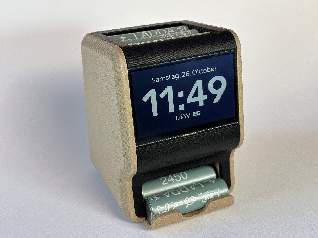
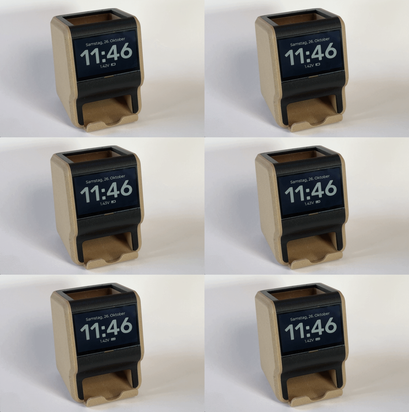
SPINC is an Open-Source NiMH charging station that can automatically load and eject AA battery cells. Simply drop batteries into the top of the device, regardless of their polarity. The internal mechanism picks up one cell at a time and fast-charges them sequentially. Up to 7 fully charged batteries can be conveniently stored inside the device for easy access. In addition, SPINC doubles as a desk clock, displaying the date and time on its high-resolution LCD.

Some of the key features:
• Fast-charges AA NiMH cells at up to 1A
• Automatic cell loading and ejection
• Electronic polarity-correction
• Voltage, temperature and charge time monitoring
• 240x400px monochrome LCD
• Date and time display using LVGL interface
• Compact and fully 3D-printed

Layout files, code and STLs on GitHub: https://github.com/CoretechR/SPINC

Not all battery chargers need to be boring power adapters, where you manually plug in every cell. Having a gadget that automatically inserts batteries, charges them and also acts as a little storage for rechargeable batteries seemed like a nice project idea to me. While a basic 4-cell charger might be faster and more economical, SPINC offers an elegant solution that you can to showcase on your desk rather than hide away in a drawer. 

It was a challenge to integrating the automatic loading mechanism into an appealing and 3D-printable form factor. The same goes for developing the electronics that can work with changing cell polarities. If you want to learn more about this project, check out the project logs below.
  • Software

    Max.K11/08/2024 at 15:26 0 comments

    While the DS2712 handles the actual charging of the NiMH cell, the RP2040 still needs a simple state machine to control the switching of batteries. If it senses, that a battery is inside the input chute, it will move the arm up, then down to try to contact the battery. After the DS2712 signals that the charging is finished or if it signals an error, the battery will be ejected to the bottom.

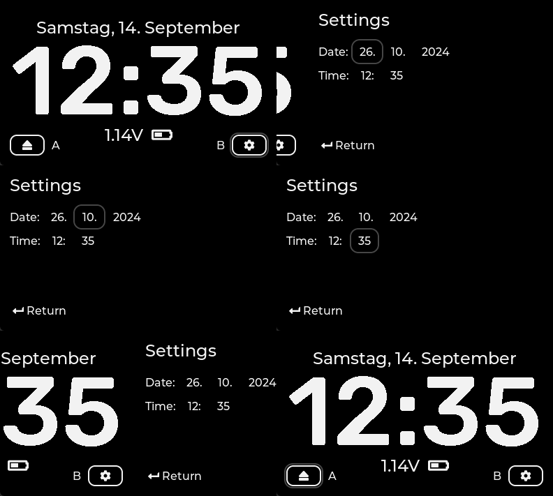
    At the same time, the display clock needs to be updated. Like with my previous smart remote project, I decided to use LVGL for the user interface. Unfortunately, drivers for the Sharp Display are not readily available and the TFT_eSPI library does not support this display either. I tried to write my own driver, but always ended up in scrambled pixels. I ended up having to use the Adafruit library for the Sharp display in combination with LVGL. The refresh rates are not great, but acceptable for a clock. Besides the date and time, the main screen shows hints for the button, when they are first pressed. One button forces the current battery to be ejected, the other opens a menu screen. The menu is mainly for setting the date and time, as the RP2040 has no way of contacting an NTP server. Since there is no touchscreen, the entire menu has to be navigated with the two hardware buttons.  I am using the Gridnav feature in LVGL, which automatically cycles through the elements on the screen. This way, the menu can be easily expanded with more settings in the future.

    Overall, I am happy with how the project turned out. It started out as a little side project, but turned out to be quite time consuming. It would probably take a lot of effort and a complete redesign to turn this into a commercial product. But not everything has to be. I see this as a fun combination of technology and product design.

  • Electronics

    Max.K11/08/2024 at 15:25 0 comments

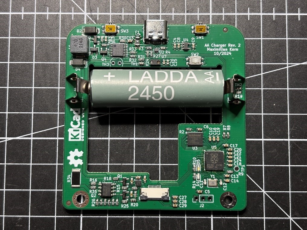
    Based on the mechanical design, I already knew how the PCB had to be shaped and how much space was left to fit the electronics. And these electronics had to fulfill a number of features: Charge the battery, drive the display and interact with sensors, buttons as well as the servo motor. The charging would have to be quick, since the device can only charge one battery at a time. And because batteries are just thrown into the top of the device, it would have to work with any polarity. This is quite an unusual requirement for a charger, as they usually have mechanically coded terminals and will simply not work with the polarity swapped.

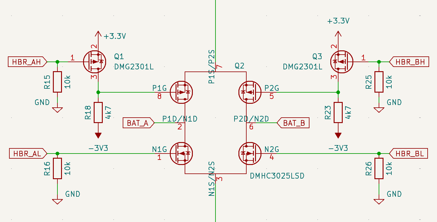
    I decided to start with the seemingly trickiest part - the polarity inversion. The usual solution for changing the polarity of something like a DC motor is an H-bridge. An H-bridge consists of four switches arranged in an H-shape, with the load in the middle. Depending on what switches are closed, the voltage at the load can be reversed. You could use relays as switches and operate them with a microcontroller. But with the limited space on the board, that is not practical. Instead, I went with an H-bridge IC (DMHC3025LSD). It is actually intended for DC motor control but in the end it’s just two p-channel and two n-channel MOSFETs in an SO-8 package. Instead of the supply voltage for the motor the charging circuit will be hooked up to the H-bridge and instead of the motor as a load it will be a battery. But there was one problem to figure out. At the top of the H-bridge, which controls the positive supply voltage to the battery, the two p-MOSFETs will only have a very low source voltage of around 1V. The MOSFETs will turn on when their gate-source (VGS) reaches are a threshold between -1V to -2V. But when the gate cannot go lower than 0V, the VGS might not be enough to fully turn the MOSFET on. This leads to increased resistance and losses, which could interfere with the charging. My solution to this was to simply drive the p-MOSFETs with a negative voltage. How do you get a negative voltage? I found the LM27761, which is a tiny switched-capacitor voltage inverter, that needs only minimal components to invert the 3.3V supply voltage. Another set of MOSFETs makes it possible for a microcontroller to switch the H-bridge gates between +3.3V and -3.3V.

    I tested this in LT-Spice first, which seemed promising. On the final PCB the voltage inversion circuit worked out perfectly as well. It might still be an overcomplicated solution, so I would love to hear in what other ways this could be solved.

    To determine which way the battery was inserted, the two contacts in the middle of the H-bridge are monitored by ADC inputs of the microcontroller. A simple voltage divider shifts the voltage up, so the input pins cannot get damaged by the negative voltage. With this setup, the microcontroller first checks in which orientation the battery was inserted. Then it can configure the H-bridge to connect the battery and the charging circuit in the right way.

    Next, I needed to find a NiMH charging controller. I briefly considered building on myself, but that seems like a major project in itself. Unlike Lithium-Ion batteries where the charging just requires a constant current and voltage, NiMH cells are actually more difficult to charge. The difficult part is determining when the charging is finished, as NiMH batteries do not have a linear voltage curve. Fast chargers do this by detecting when the battery voltage slightly dips at the end of the charging process. If you miss this moment, the cells get overcharged and potentially damaged. As a safety feature most chargers also monitor temperature and charge time. The only other way of charging is trickle charging. NiMH cells will allow a certain continuous charging current where they do not overheat when overcharged. But this means charging for many hours, which is not ideal for a sequential battery charger. My first candidate for an integrated charger...

    Read more »

  • Hardware

    Max.K11/08/2024 at 15:19 0 comments

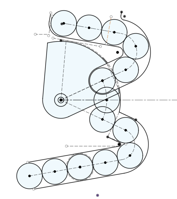
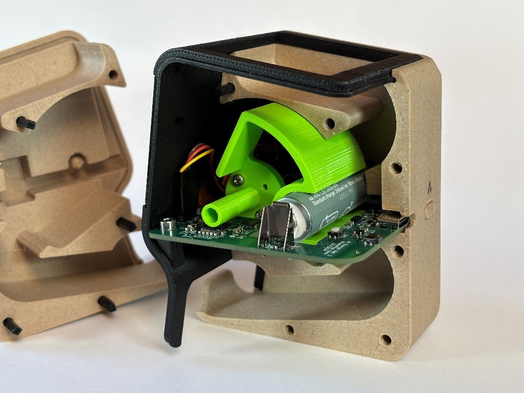
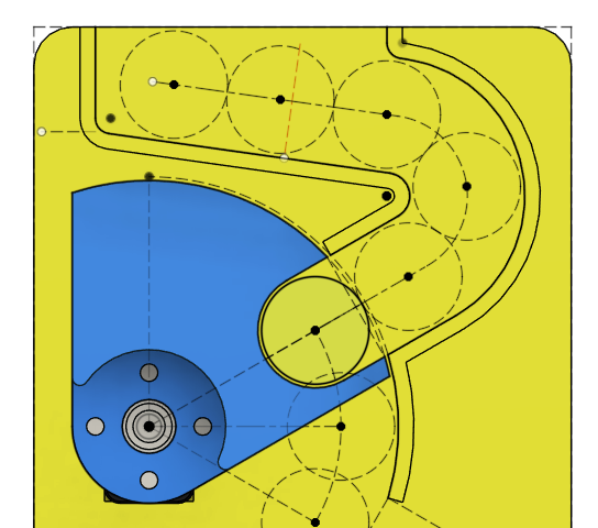
    SPINC is supposed to always sit on your desk and serve as a charger, battery storage and a clock. For that, the design had to be as compact as possible and look good in its office environment. I started out with a 2D sketch of the autoloader mechanism, to see how much space was needed. With this setup, the top and bottom chutes each fit six batteries, which seemed like a sensible amount. Between the cutes, the rotating arm is mounted that can move a battery between three positions: Up to load in batteries, middle to charge, and to the bottom for ejecting the cells. In its lower position, the arm also has to block the input chute.

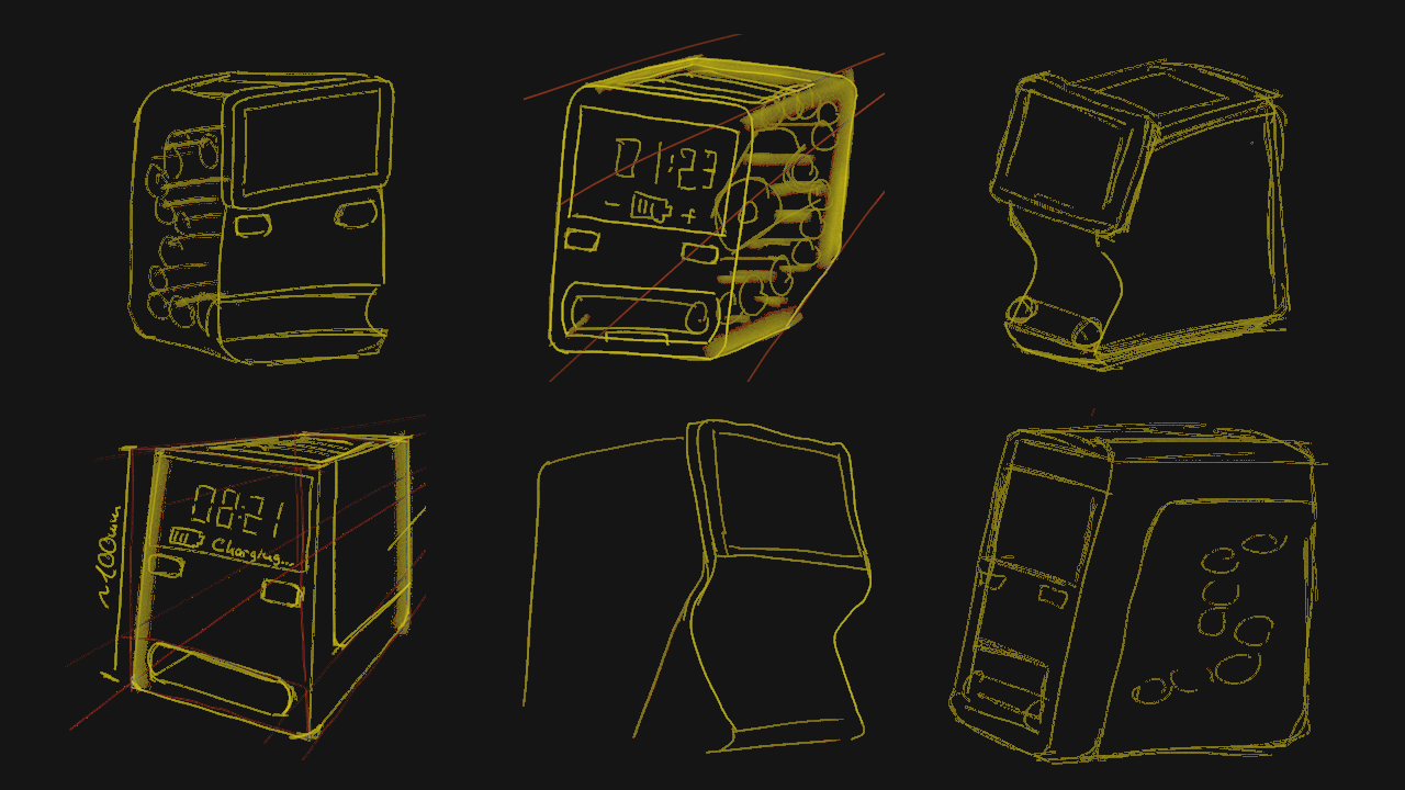
    The next step was finding a nice enclosure geometry to fit around this mechanism. It needed an opening on top for dumping in empty batteries and a second opening to pick up the charged cells. I also wanted to have the 2.7” Sharp LCD (LS027B7DH01A) on the front to display the charging status and a clock. And finally, a PCB had to fit somewhere in between. With my previous projects, I took inspiration from retro tech or similar existing products. But since this is a very unusual device, it was difficult to come up with a design that was both appealing and functional. I did lots of sketches and even printed a mockup.

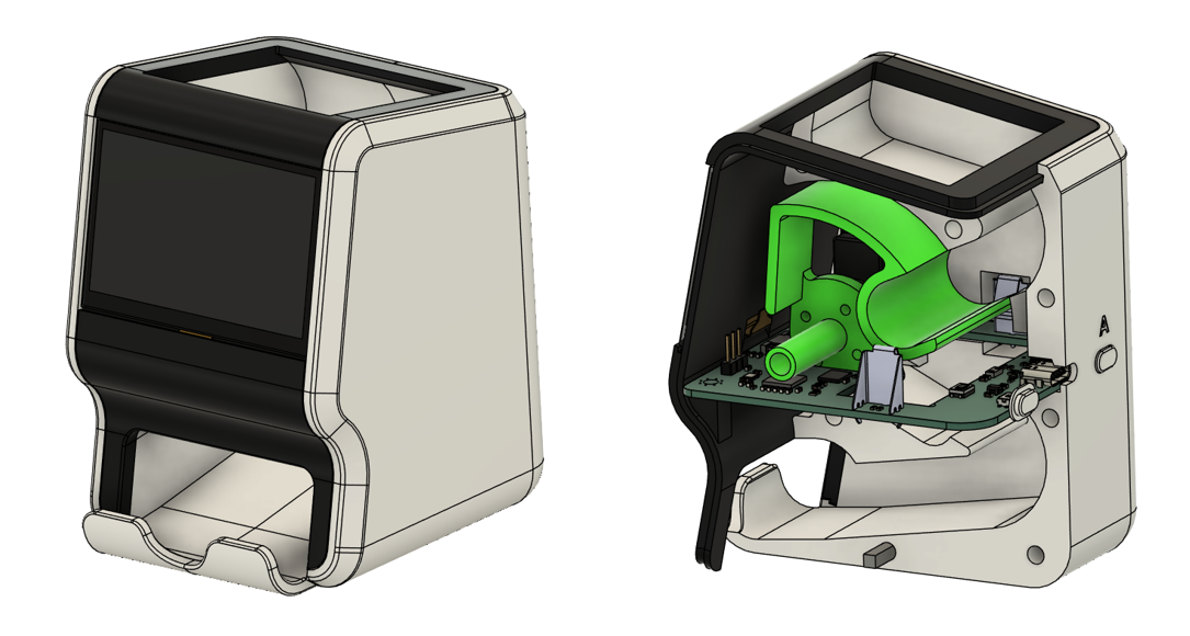
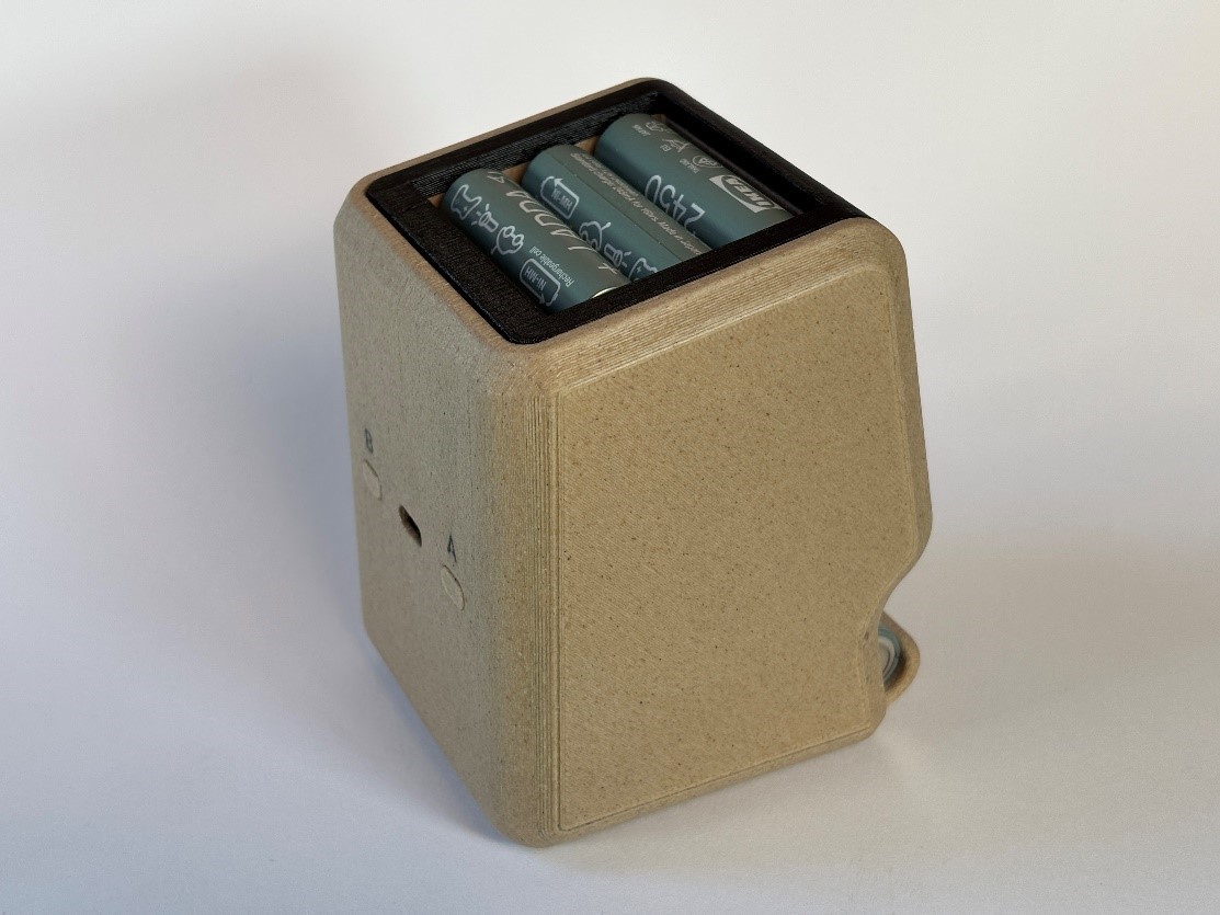
    The final design consists of three main pieces: Two halves form the main body of the charger. The input and output chutes for the batteries are also defined by these halves. The third part covers the front and top of the charger. It holds the display and circuit board. What is neat about this design is that only a single PCB is needed for all the various function. It is just in the right spot to contain the battery terminals, the USB port, pushbuttons and the display connector. And the PCB even has one more purpose: The charger needs to know if a battery was inserted, or else it has to constantly rotate the arm up and down. This is done by having an optical proximity sensor on the PCB, pointing at the input chute.

    Apart from the three enclosure parts, there is also the arm that moves the batteries. With one side connected to an EMAX ES08A micro servo and the opposite side suspended in the right enclosure half, it is very securely held in place.

    For most of my previous projects, I designed the enclosures to be printed with the inside facing the print bed. This makes for a nice outer surface, but requires lots of supports. It turned out that the rough surface that is left after removing the support, leads to batteries getting jammed in the sloped chutes. Instead, I had to print the halves with the outside facing the print bed. I used matte black PETG filament from Colorfabb for the front cover and wood PLA from Black Forest Filaments for the main body. I think this way, the device fits in nicely on a desk.

  • A Dive into Energy Harvesting

    Max.K11/08/2024 at 15:11 0 comments

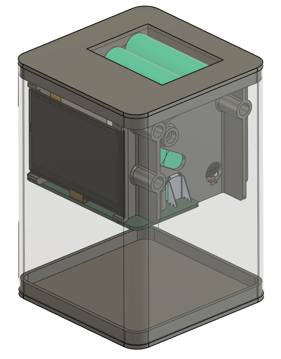
    This project did not start out as a battery charger right away. My initial plan was actually quite the opposite. Instead of charging batteries, I wanted to make use of the remaining charge in dead alkaline cells. 

    If you are like me, you probably have a box somewhere with discarded alkaline cells. Battery-powered devices like toys and remotes typically operate between 1V and 1.5V. Some devices are less efficient, so batteries might be discarded with some charge remaining. Instead of just throwing these cells into a box, I wanted to build a device that tries to utilize the remaining charge. Basically, a smart storage box that can also power a clock with depleted cells, before they are recycled. To process multiple cells, this device would require a mechanism to feed the cells in, make electrical contact, and finally eject them. A small rechargeable battery or supercapacitor would be used to bridge the time when no battery is inside the mechanism. And to charge this buffer battery, the device would need to step up the alkaline battery voltage to a more usable 3.3V or more.

    The first step was figuring out a simple and compact mechanism for loading and unloading the batteries. I came up with an approach that uses only a single motor. First the batteries are stored in an angled chute. This way, gravity can feed the batteries into the mechanism. A servo motor drives an arm that can move the battery between three positions: In its upper position, the arm connects with the chute and allows a battery to roll into it. Once the battery is inside the arm, it can move to its middle position, pushing the battery into spring terminals. After the battery is fully discharged, the arm moves to its lower position where the battery is free to drop out of the arm into a collection bin. The downside to this approach is that the batteries need to be of the same size. But supporting both AA and AAA cells would increase complexity and size by a lot. 

    I 3D-printed a proof-of-concept to test the mechanism. This worked out very well, so I already planned a more sophisticated design. One of my early ideas was to make a device that resembled the Power Mac G4 with its transparent shell. The front would display a simple clock, while the transparent sides would show off the inner workings of the mechanism.

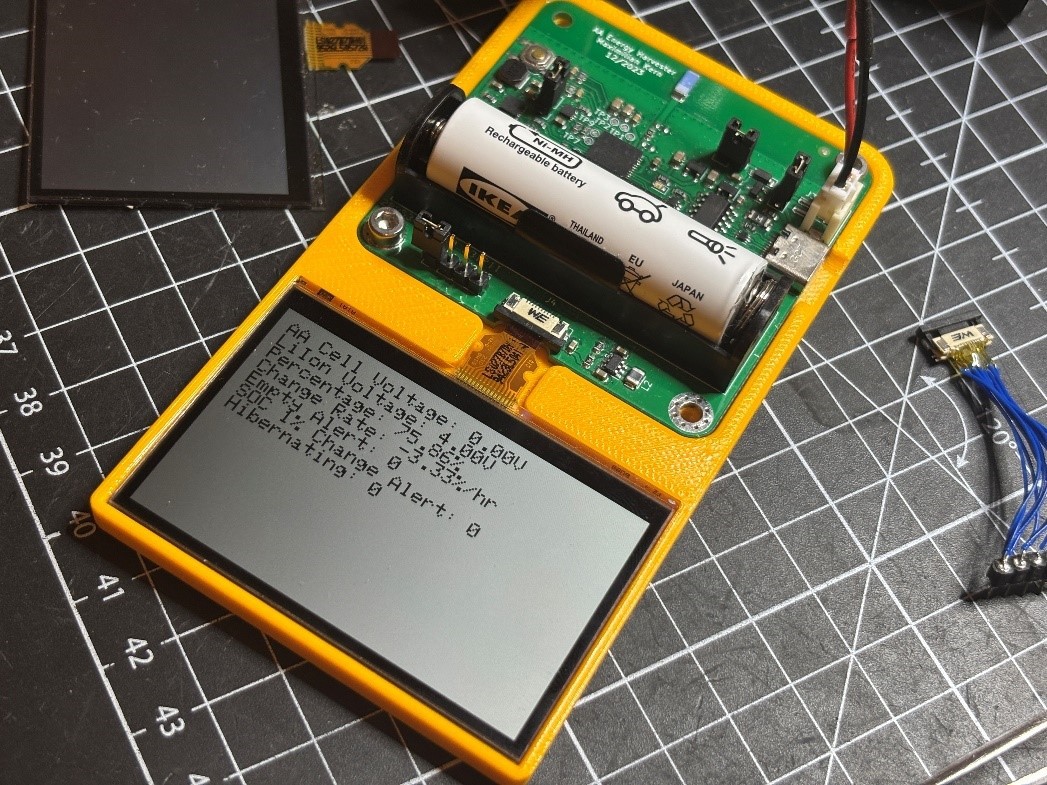
    While working on the mechanical design, I had already ordered a PCB to test the electronics. It contained a BQ25504 energy-harvesting IC that can use voltages as low as 600mV to charge a small Lithium-Ion battery. This battery was powering the servo motor as well as a Sharp memory-in-pixel display and an ESP32. While the basic concept worked, I soon found a problem: Out of my collection of old batteries, most of them were so empty that the voltage collapsed entirely, even when charging the Li-Ion battery at the slowest possible rate. The batteries that did not collapse seemed to be well over 1.2V and barely used at all. 

    It appears that most battery-powered devices are in fact pretty efficient and use most of the energy in a cell. There is a very interesting blog post that shows how batteries behave when discharged at different rates:

    https://lygte-info.dk/info/batteryEnergyAtLowVoltage%20UK.html

    Even when using cells with enough remaining energy could power my device, I had become unsure about my goal with this project. Powering a simple clock with half-empty AA batteries did not seem too exciting. Also, the internal buffer battery could power the clock for months or years without needing to be recharged. And while the mechanism seemed interesting, it would only ever move when a battery is switched for a new one, which could take weeks. Disappointed, I put the project on hold. 

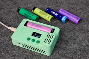
    A few weeks later I stumbled upon a Kickstarter campaign by Olight. They had built a battery charger that in many aspects resembled my prototype. The Olight Ostation X has a battery storage on top, where empty rechargeable batteries are dropped in. They...

    Read more »

View all 4 project logs

Enjoy this project?

Share

Discussions

DeFlanko wrote 12/04/2024 at 18:10 point

I would handsomely buy one of these.

  Are you sure? yes | no

SpaceBug199 wrote 6 hours ago point

Hi DeFlanko, 
I have sent you a dm with the details

  Are you sure? yes | no

Tobias wrote 11/26/2024 at 14:05 point

Amazing, great job!

Any chance I could buy the PCB fully assembled somewhere? I'd need some of them for my school :-)

  Are you sure? yes | no

SpaceBug199 wrote 6 hours ago point

Hi Tobias, 

I have sent you a dm with the details

  Are you sure? yes | no

Ian wrote 11/15/2024 at 19:47 point

Have you considered a wireless version powered by a stack of AA batteries? 

  Are you sure? yes | no

Jon Xuereb wrote 12/17/2024 at 20:16 point

you've missed the purpose of this being a battery charger not just a clock

  Are you sure? yes | no

mihai.cuciuc wrote 11/09/2024 at 11:04 point

Wow, love the concept! Anything that lowers the barrier towards using rechargeables is a win in my book

  Are you sure? yes | no

Similar Projects

Does this project spark your interest?

Become a member to follow this project and never miss any updates