Close
0%
0%

Sojourner Mars Rover

Motorized Sojourner Mars rover model.

Similar projects worth following
My plan is to build all the Mars rovers and I thought I would start at the start and work my way up. I could find no Sojourner model that meets my needs; to be as accurate as possible, be 3D printable and automate the movement. The model is scaled such that only the largest part has to be split in two to fit on a standard 3D printer, i.e. 220mm or smaller. The largest part on this model is the top solar panel. This gives a 1/2 scale model. The rover will move via solenoids and geared motors. These will be controlled with an Arduino. Since I already have the Earth Rover that has all the sensors and a Raspberry Pi to wirelessly present a web page for rover control, the decision was made for this model to be controlled via a removable wired joystick and no sensors to keep the cost down. It would be easy to add a pair of cameras and laser range finders along with a Raspberry Pi if desired.

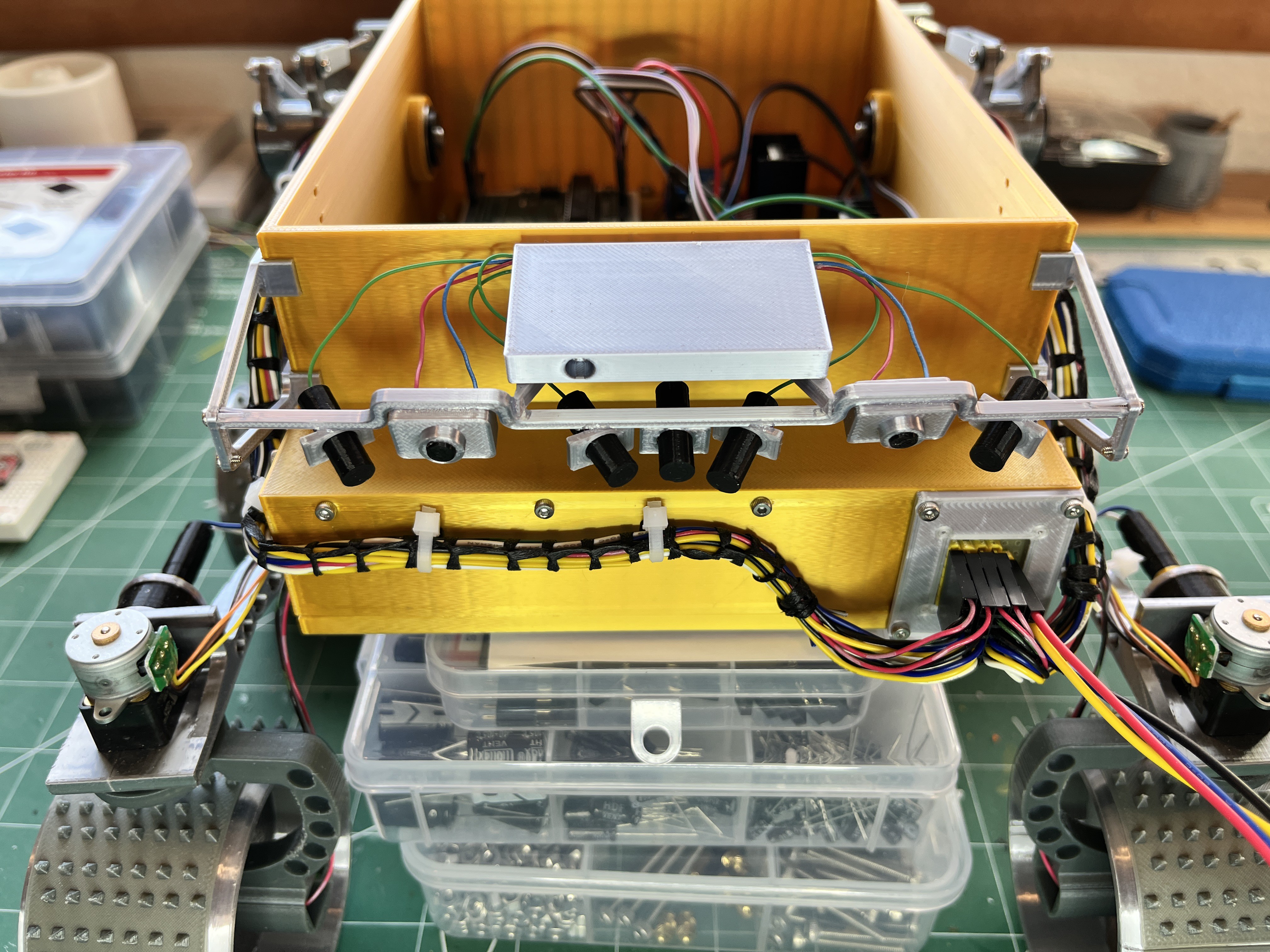
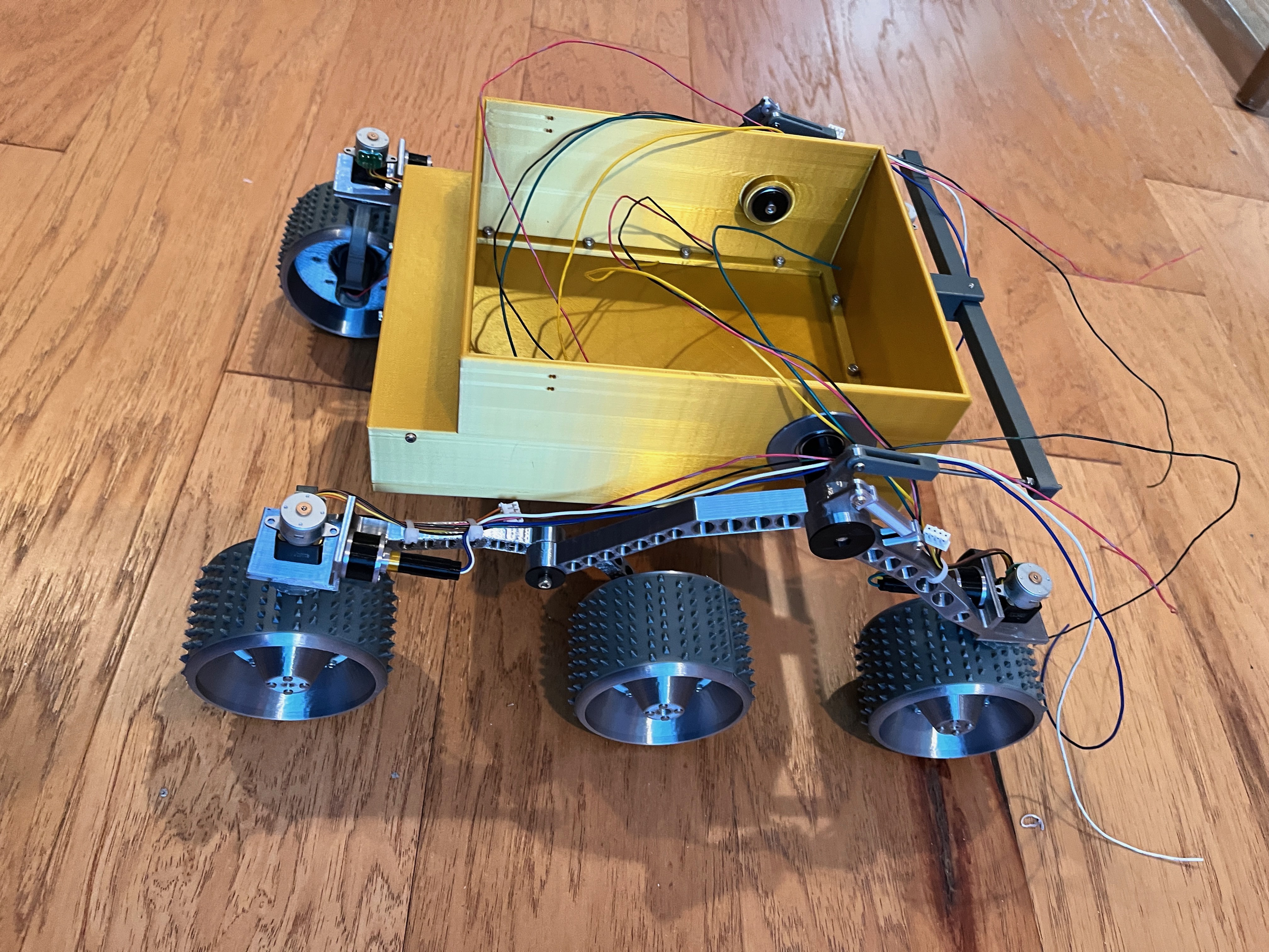
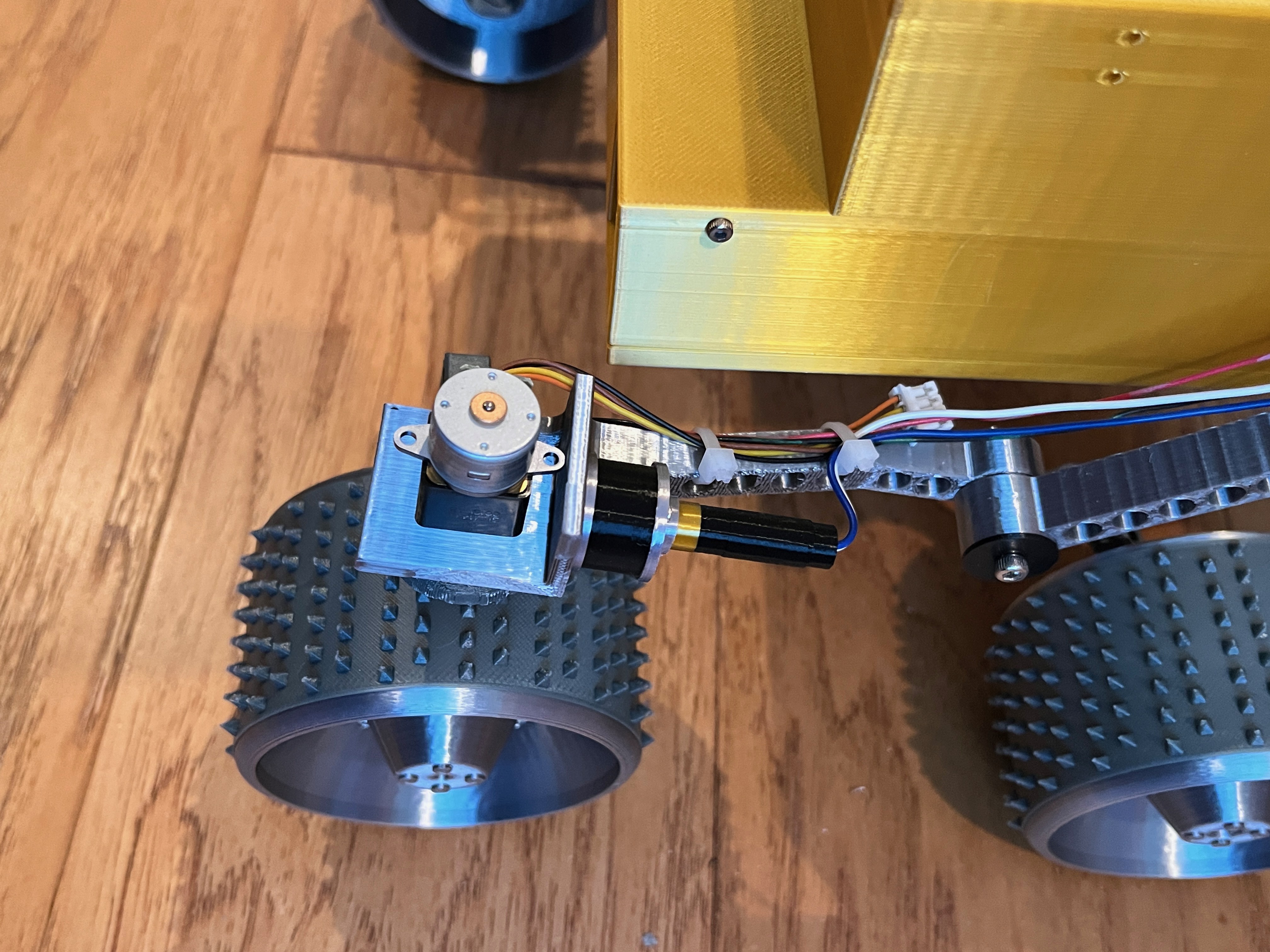
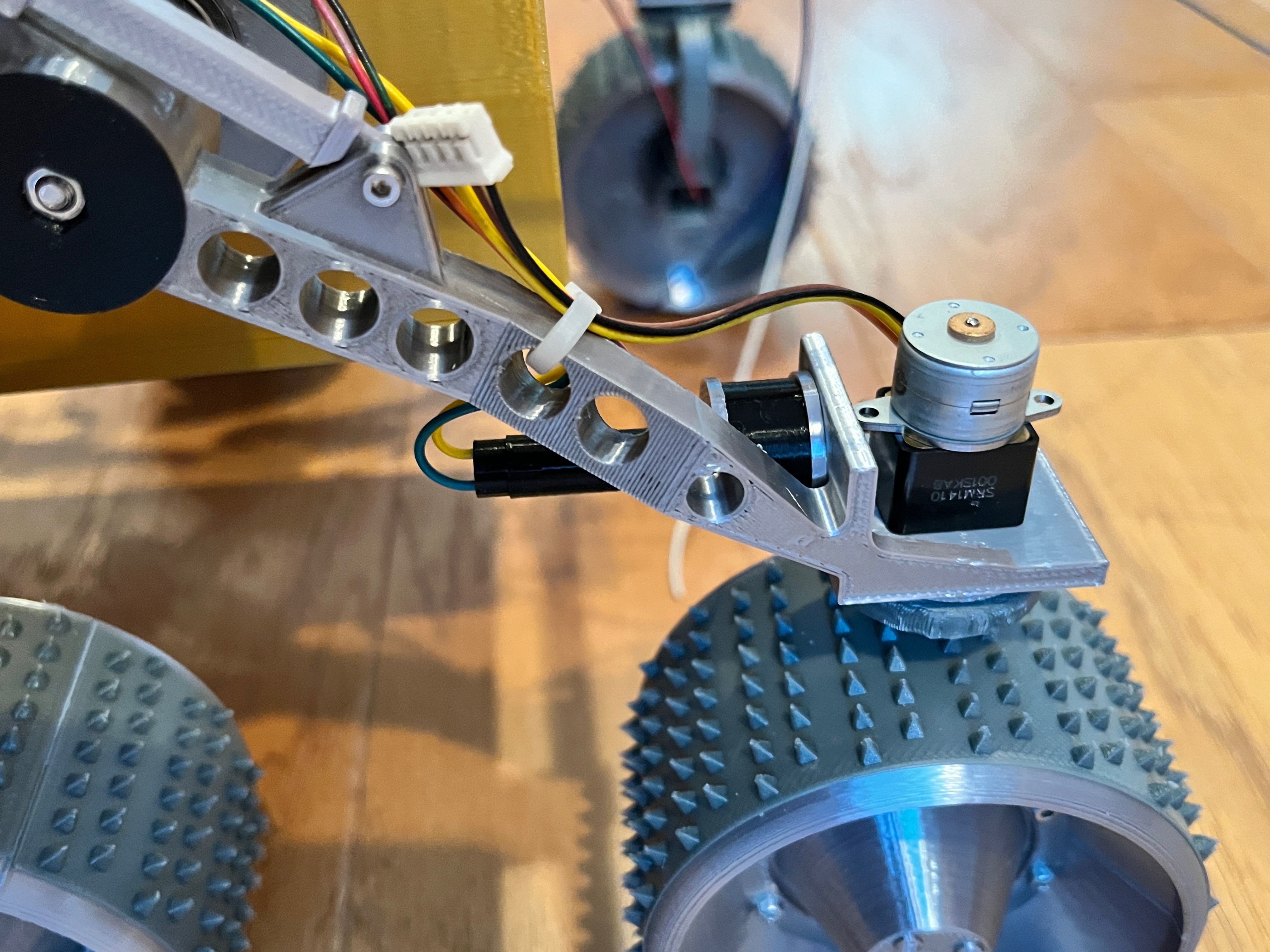
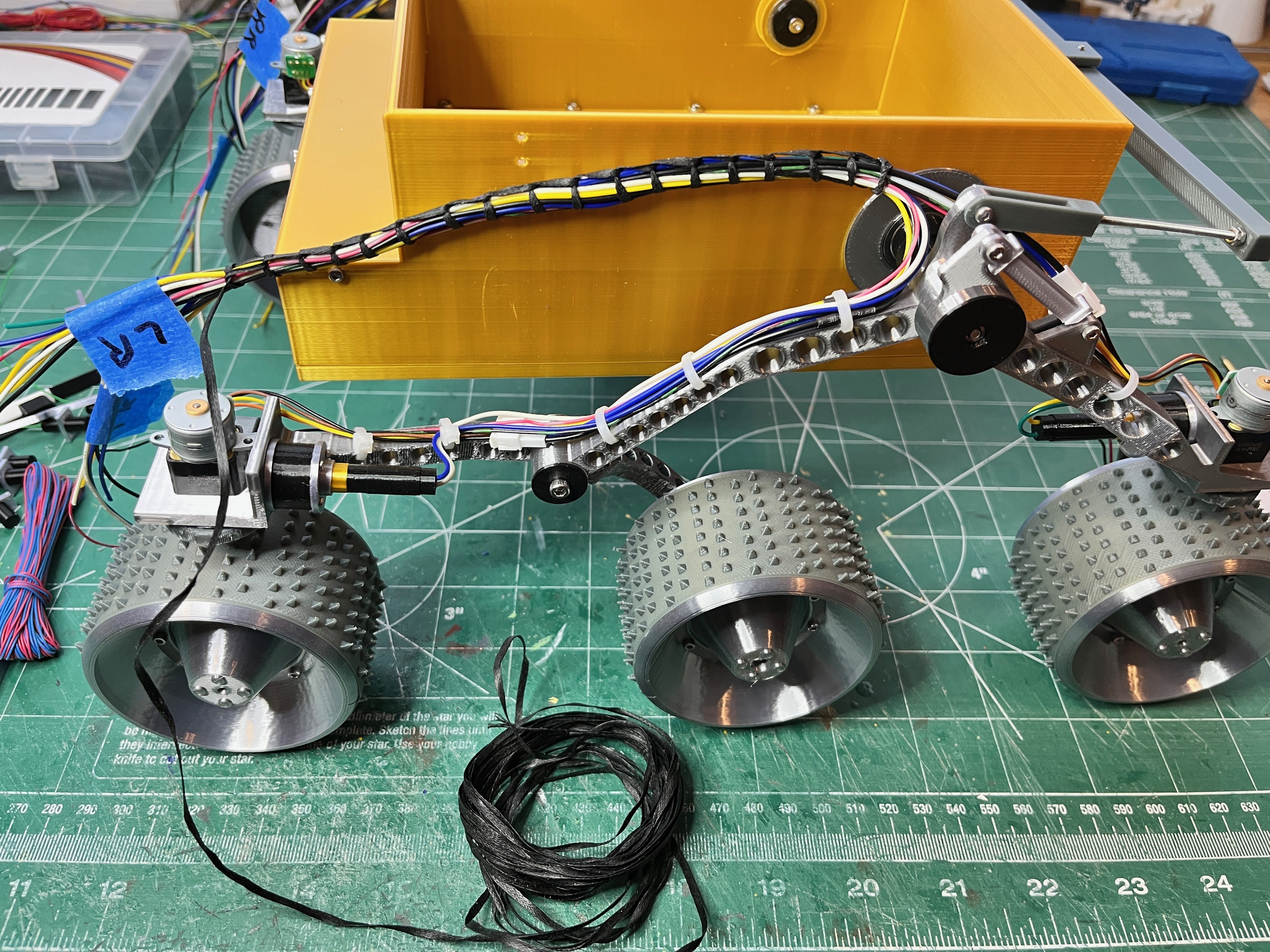
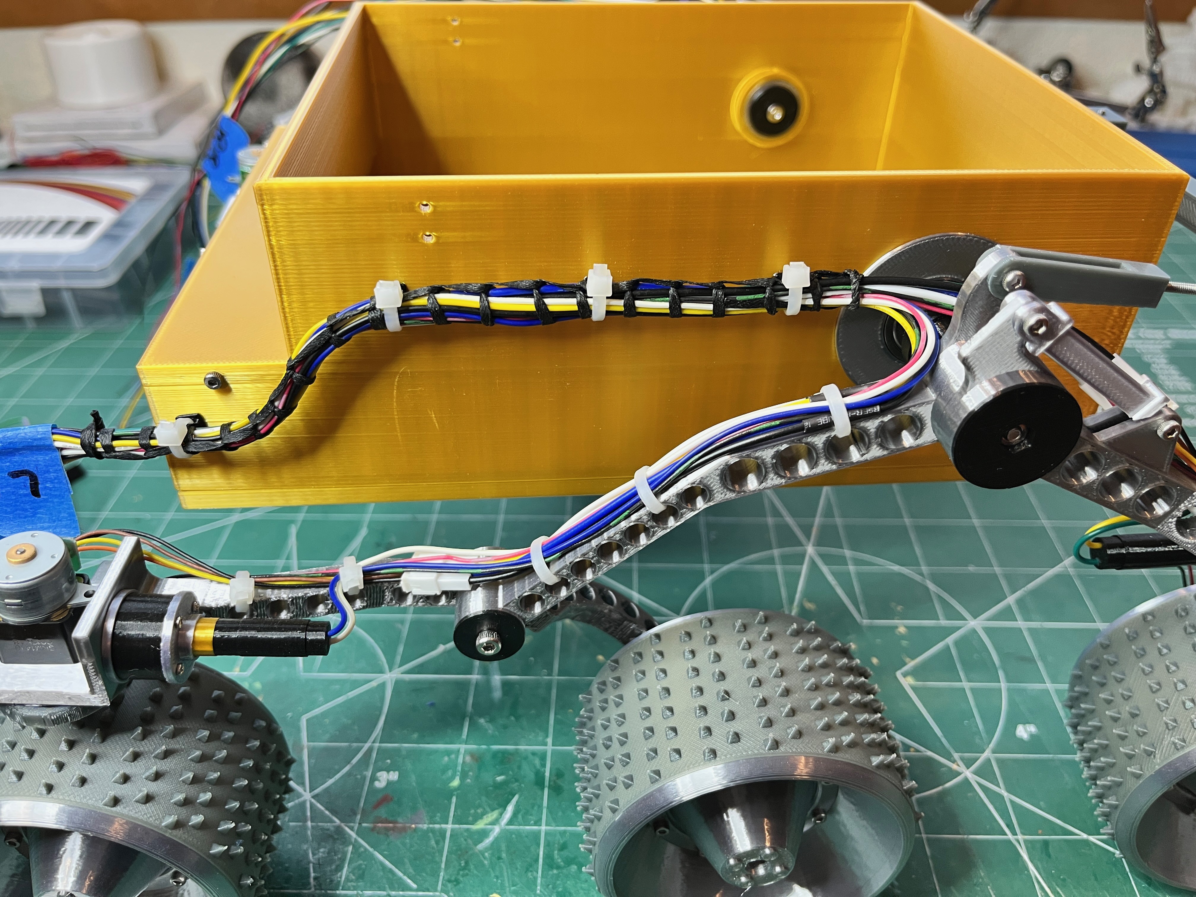
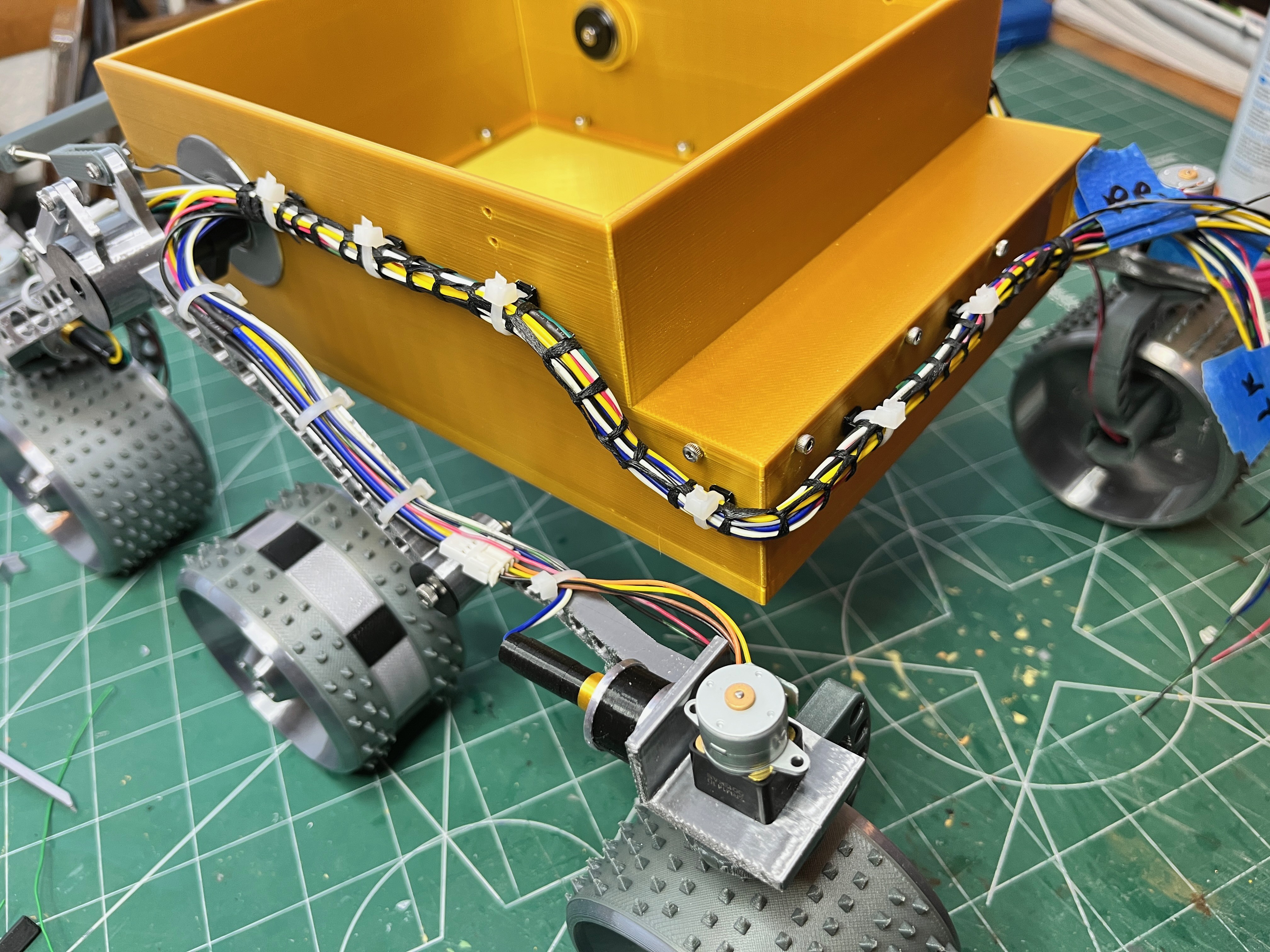
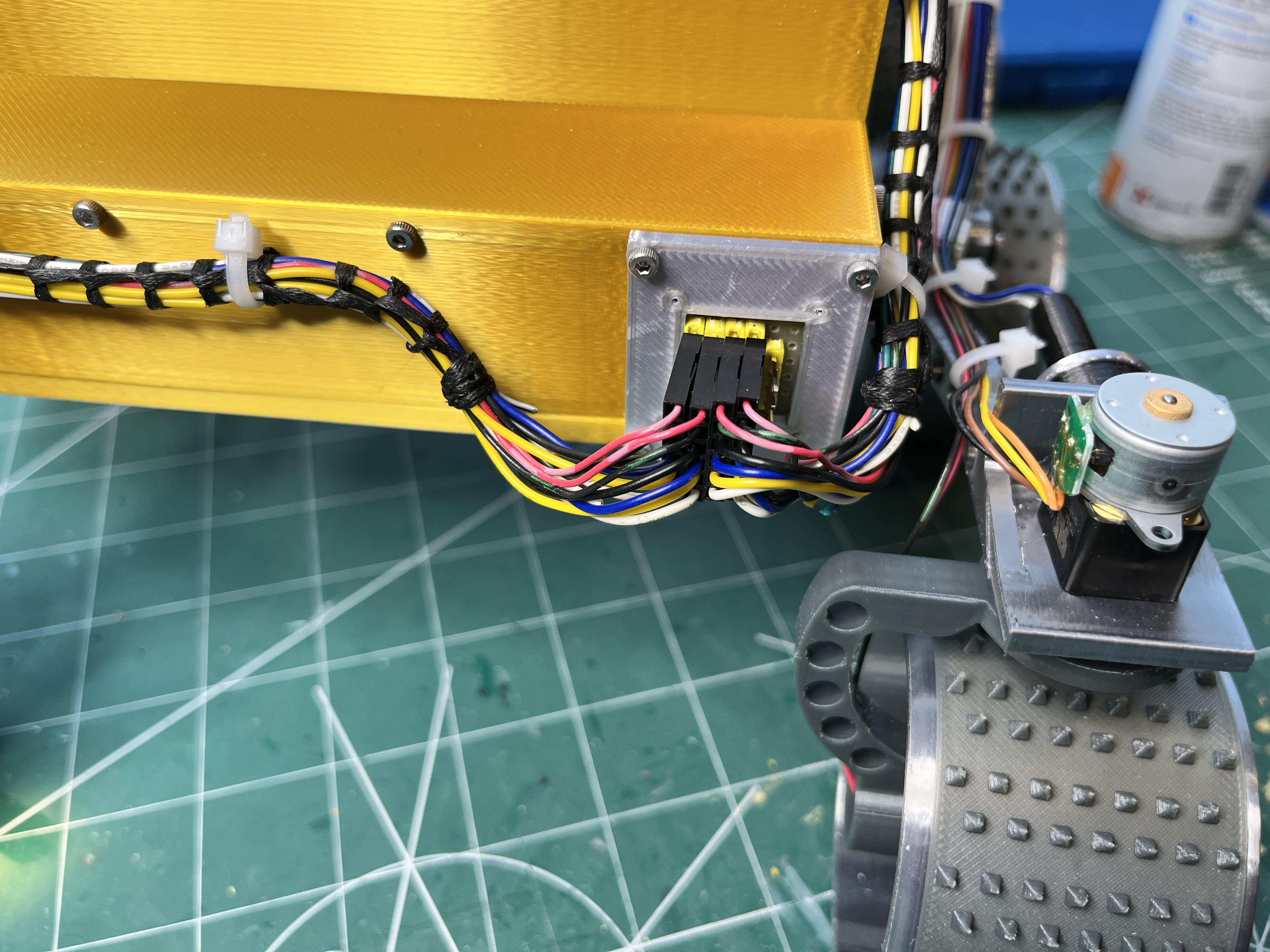
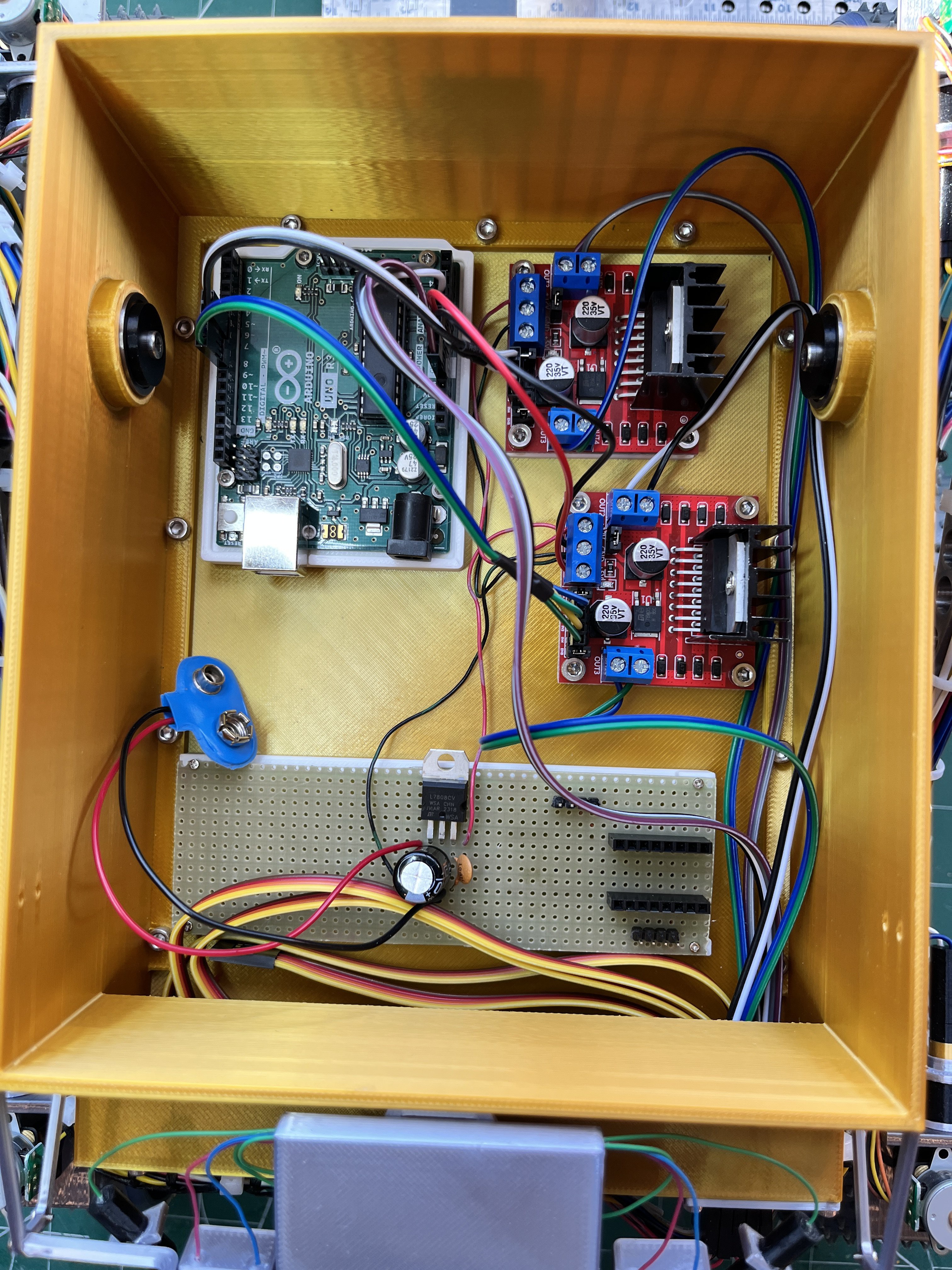
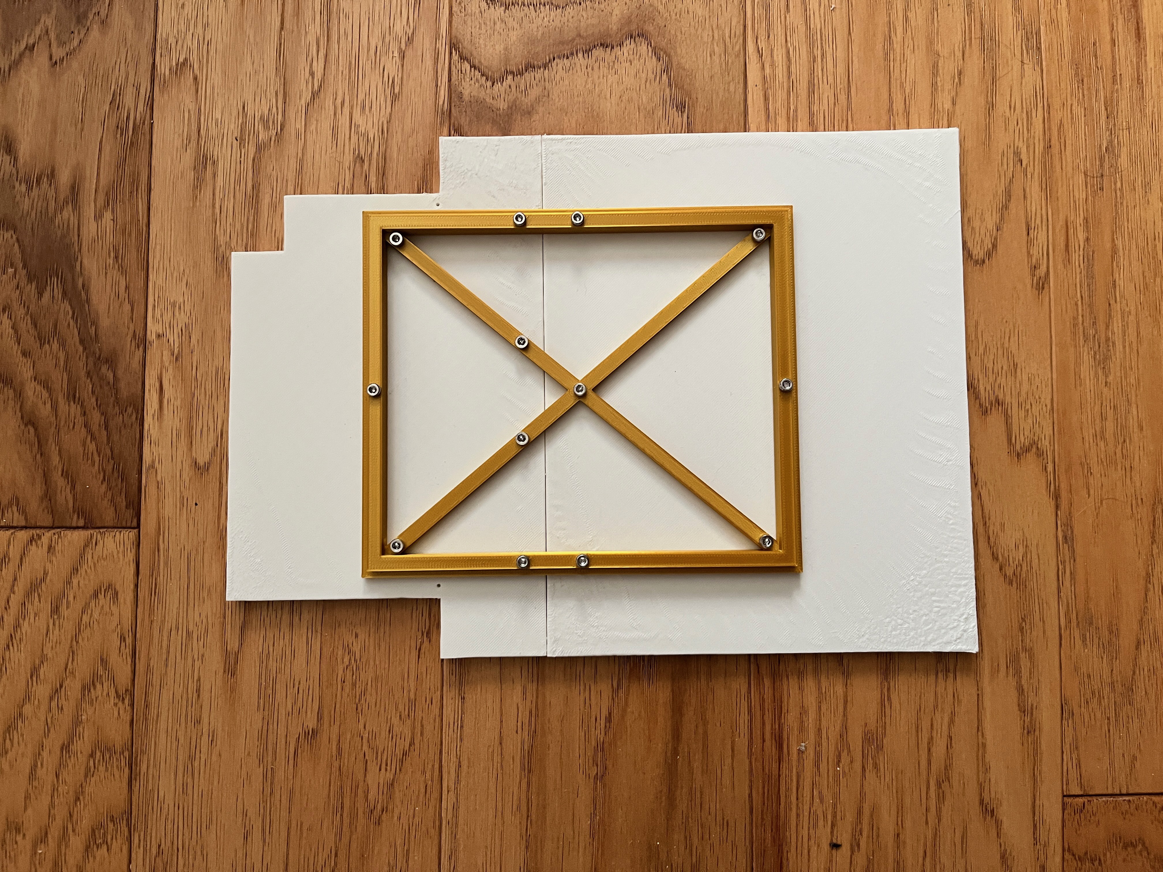
The real rover has six driven wheels.  For simplicity only the four corner wheels will be driven and the two middle wheels will rotate freely.  The steering is accomplished using four servos, one at each corner wheel.  The go to steering maneuver for this rover seems to be turn the four corner wheels in and rotate in place.  All of these motors will need motor drivers.  For this I chose the L298N motor controller modules requiring 4 digital output pins.  One module can drive two DC motors.  Each stepper motor is driven by an A4988 stepper motor driver requiring 2 digital output pins.  The directional input is via a joystick requiring 2 analog inputs.  The total input/output count is 12 digital output pins and 2 analog input pins.  A single Arduino Uno should work for this project.  

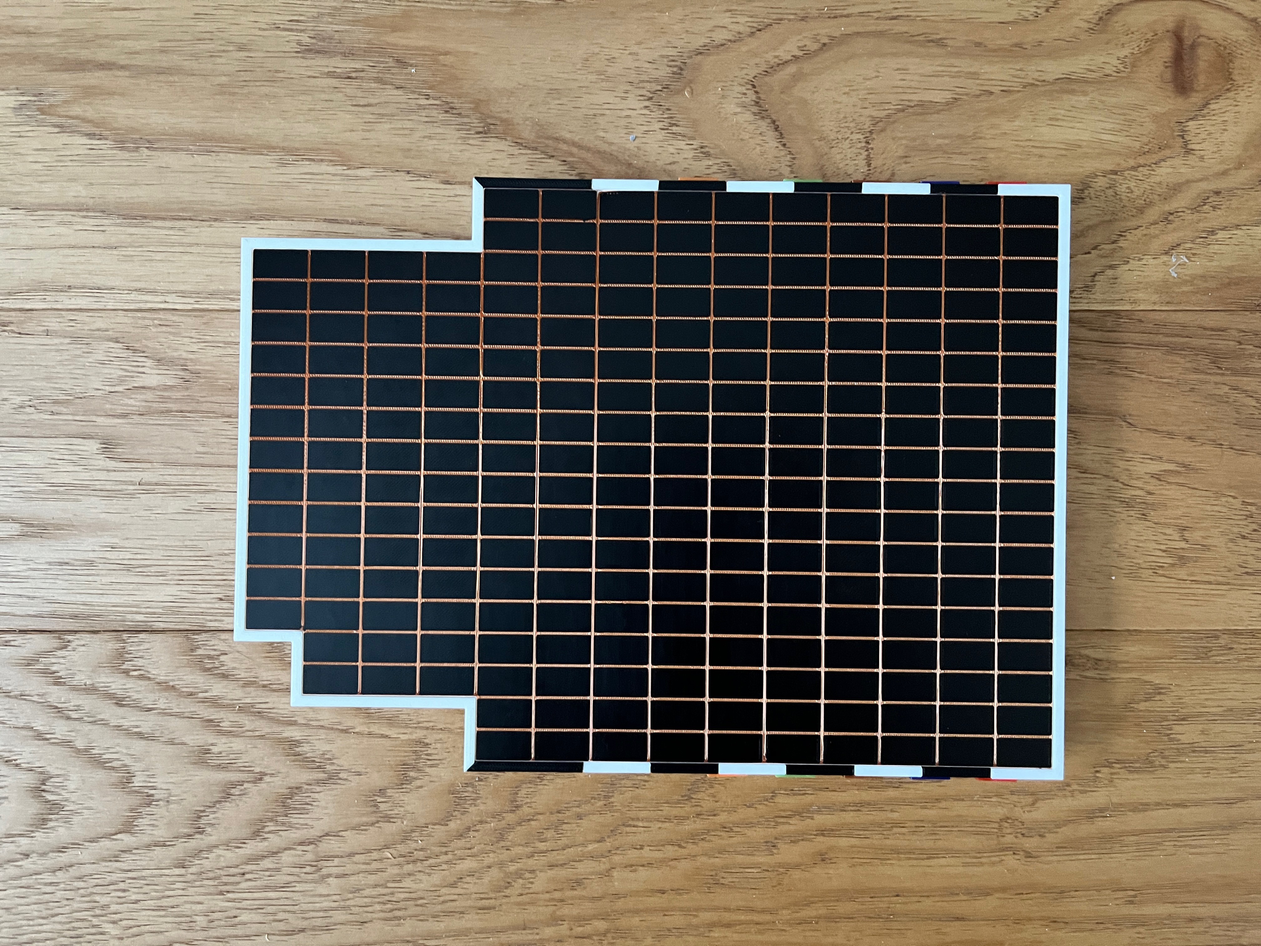
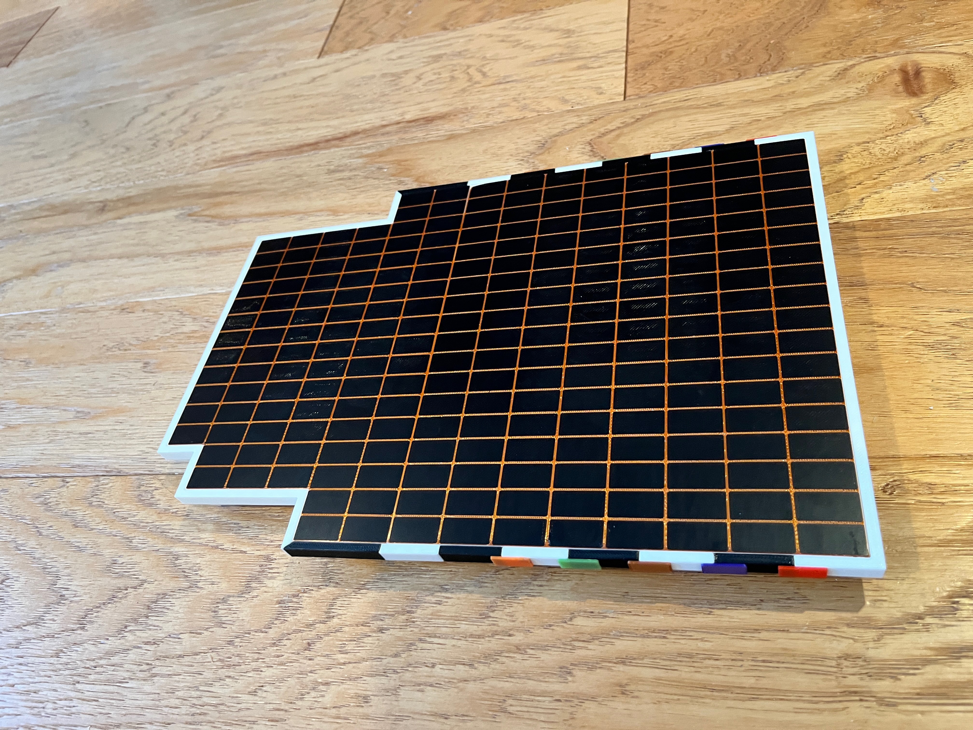
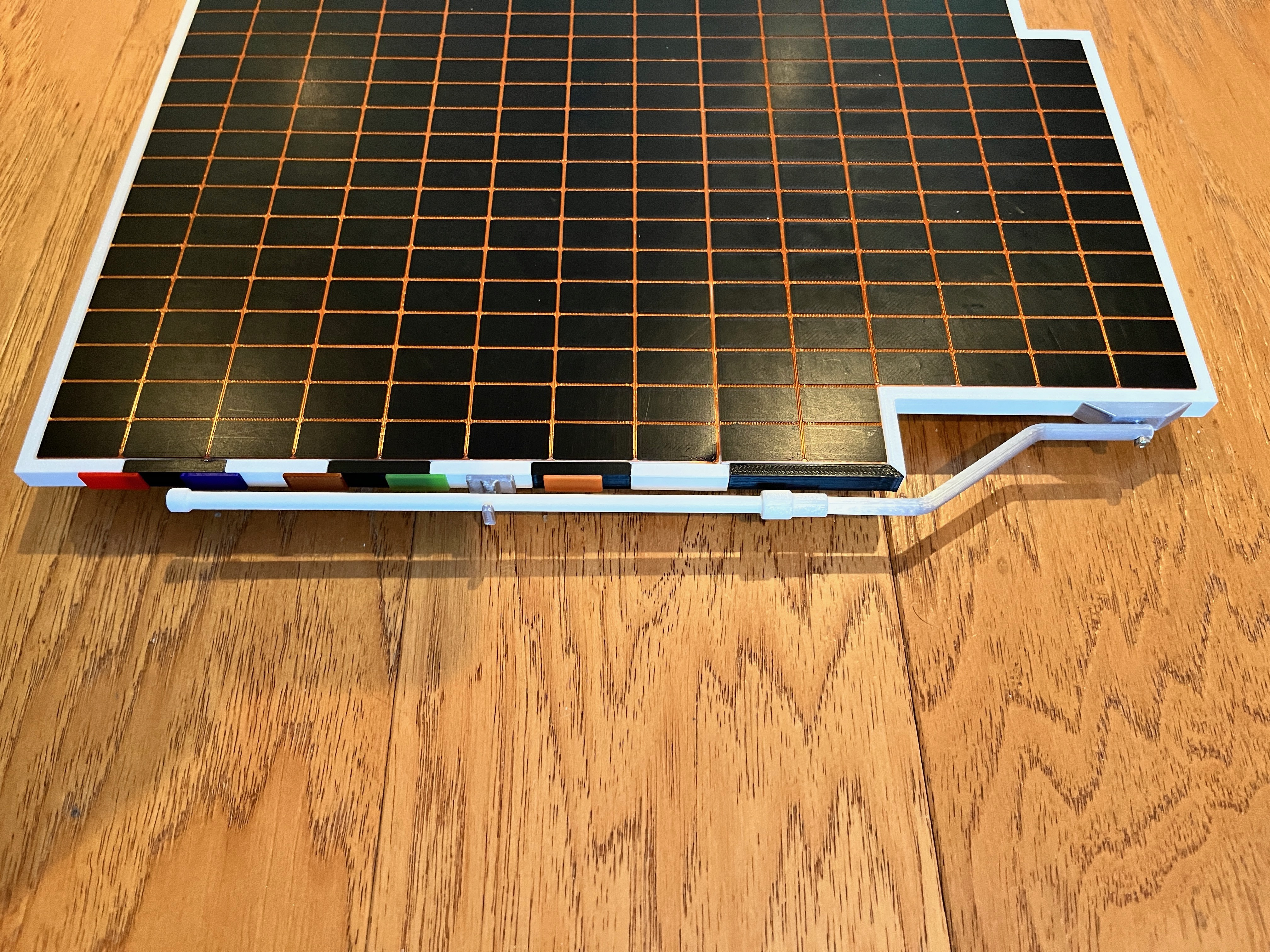
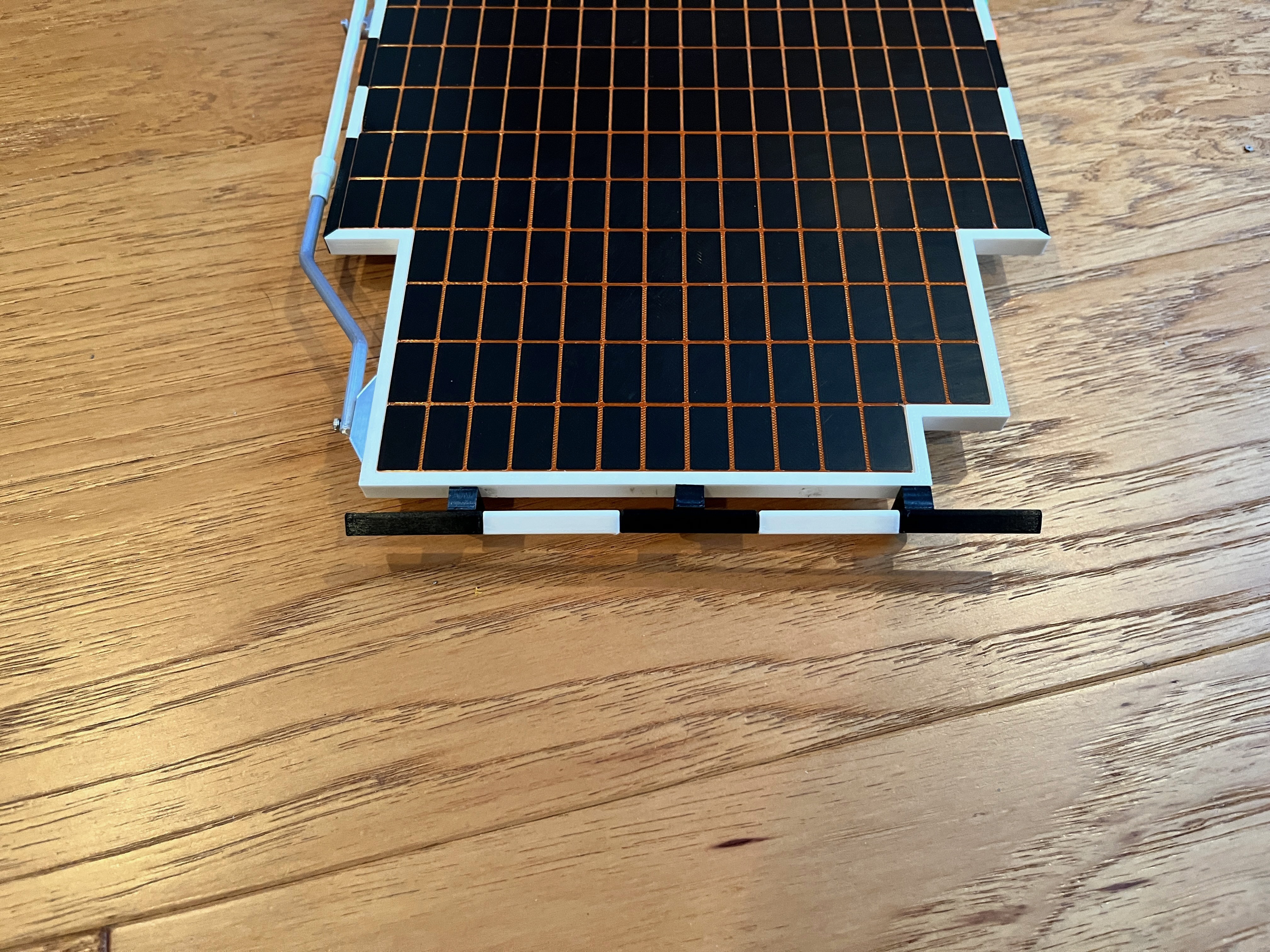
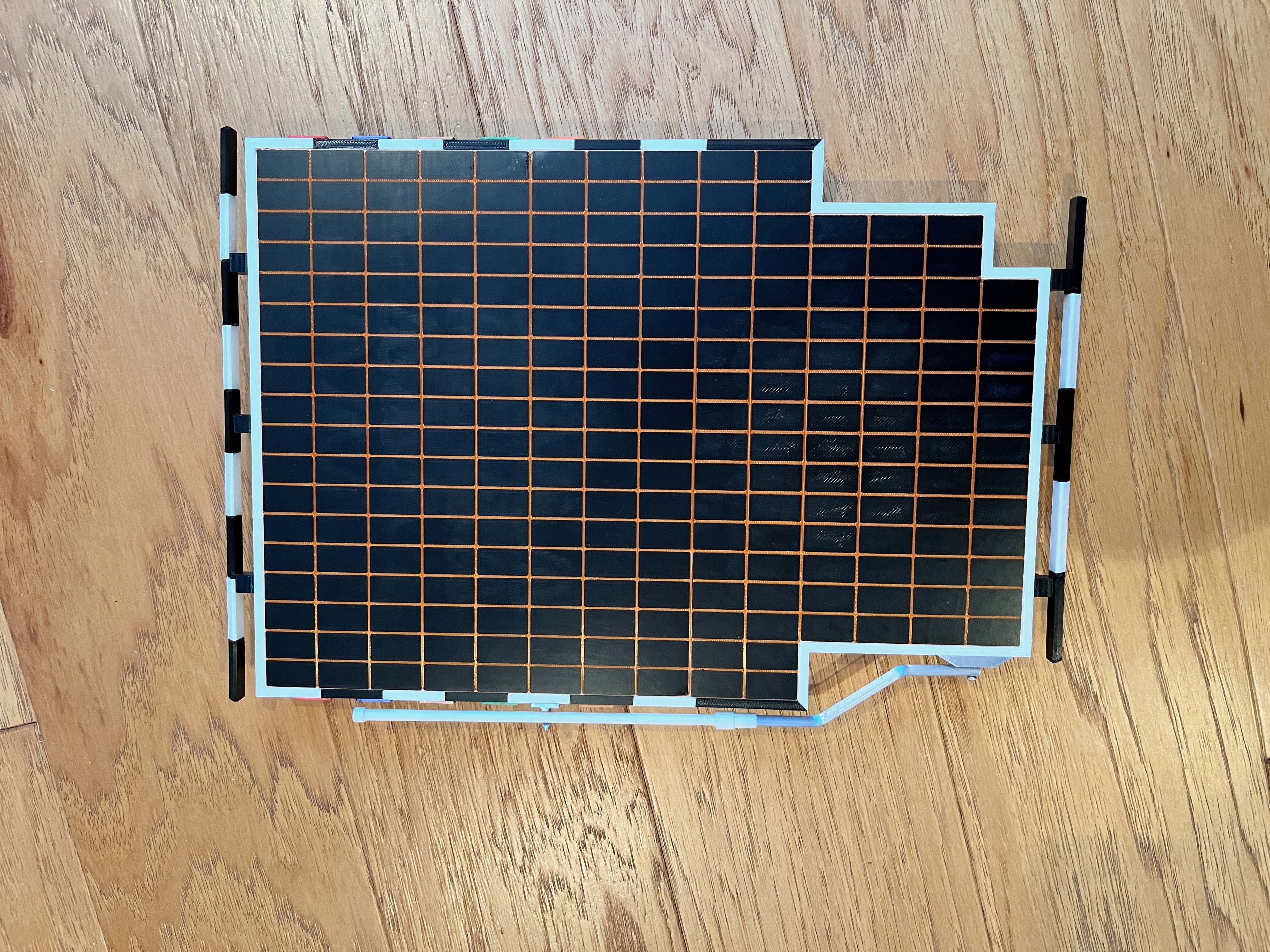
The color of the 3D printed parts are chosen to be as accurate as possible.  Some of the parts are printed using filament changes to produce more accurate looking parts and keep the assembly to a minimum.  One example is the solar panel.  The base of the panel is white with a single height copper layer followed by black solar panel modules.  Most slicers should be able to perform this trick including Cura and the Prusa slicer I use.  

In the end the scale stepper motors work fine on the bench but are too weak to turn the wheels with the weight of the rover on the wheels.  I chose to not upgrade the motors to a something was not to scale.  As an alternative I included fake motors for anyone that wants to build a static version of the rover.  The wheels will pivot and rotate but would not be driven by motors.  If this is the way you choose to go, I would strongly suggest you include fake wires as that really adds to the realism of the model.

The 3D printable parts and install instructions are located on my Printables page at https://www.printables.com/@bglasford1 

Sojourner Parts List.pdf

Adobe Portable Document Format - 150.92 kB - 02/16/2025 at 17:10

Preview

Sojourner Schematic.pdf

Adobe Portable Document Format - 101.52 kB - 02/15/2025 at 17:35

Preview

SojournerRover.ino

The Arduino code. Notice that the stepper motors that rotate the wheels is not implemented.

ino - 6.58 kB - 02/15/2025 at 17:35

Download

  • Final Assembly

    wglasford02/15/2025 at 17:34 0 comments

    There are a few remaining items to add to the rover.  First is the front cameras and laser range finders.  The wires are not functional but add a lot to the looks of the model.

  • Instruments and Wiring

    wglasford12/05/2024 at 15:24 1 comment

    The instrumentation has wires running along the outside of the body along with the wiring to run the motors and servos so all this is added at the same time.  Here are pictures of what look like rotational sensors on the corner wheels.  Some of the wiring is starting to be zip tied to the rocker/bogie arms.

    I chose to use waxed tape to bundle the wires together.

    The wires are then zip tied to the side of the body just like the real rover.  It makes sense to label the bundles of wires, either that or ohm them out later to figure out what goes to what.

    The rear camera is easy.  The front pair of cameras and lasers are a bit more complicated.  First test fit the bar that holds them, then glue them on and finally attach the wires to a junction box.  I am holding off gluing this rather delicate structure on until I finish the wire interface board.

    The outer wires go through a plate that has two sided pins.  These could have been soldered but I chose to make them detachable.  There will be a plate that covers the wires.  The inner cable harness attaches to the other side of the plate.  

    I first tested the joystick and then the wheels moving forward/reverse.  The wheel motors are driven by two dual L298N motor drivers.  You have to make sure the wires are attached such that all four motors turn in the same direction.  After that I tried to get the stepper motors working.  They each use an A4988 Stepper motor driver.  All this worked fine in a bench test, however on the model these little stepper motors do not have enough power to pivot the wheels.  Stepper motors that have enough power to turn the wheels would be way too large and look wrong.  At this point I have decided to not implement the turning function.  The rover will only be able to move forward and backward.  Here is a picture of the interior.  There is plenty of room if you want to add additional functionality such as working sensors.  I use a L6808 to convert the 9V battery power to 8V which drives the motors.  

  • Body

    wglasford11/26/2024 at 16:14 0 comments

    The body was split into three parts; the top part that is attached to the solar panel, the main body and the bottom plate.  The bottom plate was separated so that the main body can be printed without internal supports.  

    There are holes around the front to add small M2 screws that do nothing other than to give the model a more realistic look.

  • Solar Panel

    wglasford11/24/2024 at 17:15 0 comments

    The main part of the solar panel is complete.  Since the scale is 1/2 actual size, this is the one part that had to be split in two to fit on a standard 3D printer surface.  After trying a print right side up I decided to print the two parts upside down, i.e. the top (good side) on the print surface.  These are three color prints.  The first layer should be black.  Then switch out the filament for copper and print the next two layers.  Finally switch out for white filament and let the remainder print in white.  No supports are needed because the printer easily spaned the 1mm gap between the black rectangles.  On the sides I beveled the edges at a 45 degree angle that go in 0.5mm.  After the two solar panel parts are printed, print the body interface in gold and use M3 screws to anchor the top halves together.  You could choose to glue these parts if you want but the screws work well at aligning the parts perfectly so you can't tell they are two parts.  The solar panel is the most important part since it takes up the entire top.  

    The sides of the solar panel are printed and glued on, first the two end white parts and then the sides alternating black and white.  Work from the back to the front so the last parts glued on are the long black parts with the angled ends.  For me one side fit perfectly and the other side was a bit long.  A little sanding of the end of the last part and it fit just fine.  Now print and glue on the colored strips (what I call badges).  There is a specific order.  On one side make sure you leave enough gap for the antenna park mount to go.

    Here is the competed solar panel.  I am happy with the result.  You can't tell where the two halves meet.  The other parts will go on later.  

    The antenna is printed and installed.  

    There are bumpers front and rear on the solar panel.  They consist of black and white parts that are glued together.  

    Here is the completed solar panel assembly from the top.

  • Suspension

    wglasford11/18/2024 at 15:40 0 comments

View all 5 project logs

Enjoy this project?

Share

Discussions

Similar Projects

Does this project spark your interest?

Become a member to follow this project and never miss any updates