Paul Crouch
-
I'm better than me.
03/21/2018 at 13:21 • 4 commentsI've been thinking about the head and drive mechanism not being particularly robust and judging by discussions in the Astromech builders forums, the public can be brutal with displayed droids. I doubt I'd be attending the same events but I want robust. I like robust.
Frustrated with second-guessing myself and my inability to make decent progress I have to console myself with the adage; Fail Fast, Fail Often. Iterate. Prototype. Understand that every change or "failure" is simply a step toward the new and improved version. I'm learning from everything. Nothing is wasted. Honest.
Parallel to my own internal conflicts of self-worth is the feeling that I should be putting my efforts to better use. Granted, I want to build cool robots, I can't deny that passion but it bothers me that with everything going on in the world, I'm putting my efforts into what is essentially an expensive toy. I can do better than that.
Coincidently, about this time, the Avatar XPRIZE is announced and I read the objectives, guidelines and example tasks. The goal for my robot has always been to have a tough, usable machine and the Avatar XPRIZE objectives just felt right! I'd compromised on my early goals, aimed lower and that grinds a little but I simply don't have the resources to be able to produce anything in any timescale close to that needed for the XPRIZE. I can adopt the worthy objectives though. I should at least try. And try using low cost components, materials and methods so something could be deployed for less than $1,000,000.
Too hard? Too easy says Evan Ackerman (Contributing Editor for IEEE Spectrum's Automaton), suggesting some interesting additions:
"So how could the competition be made better? Fundamentally, I think there are several different ways of looking at robotic avatars—you could consider them to be remote humans, with the goal of creating an experience for a user that’s as immersive and as much like “being there” as possible, or you could consider them to be one half of a robot-human team, where both the robot and the human augment each other’s strengths and while compensating for weaknesses."
And is in-line with my thinking:
"An avatar designed to be part of a more practical robot-human team might be much different, depending on what the system was designed to do. To use disaster relief as an example, you might not want the robotic system to be humanoid at all. You’d want the remote hardware to be capable of extreme mobility, to be very strong and durable, and to incorporate a suite of sensors that outclass anything a human has to offer, while relying on the human to make sense of the data and provide high level control of the robot. Some challenging tasks that would take advantage of this might be:
- Perform a dexterous manipulation task in a smoke-filled environment.
- Locate an unconscious human trapped under rubble, and rescue them.
- Collaborate with other humans to unload heavy supplies out of a truck.
Exactly!To that end, I'm pivoting the project slightly. Aside from some redesign for robustness, the only real changes are more focus on making the arms more usable and the addition of some kind of stereoscopic vision system and remote HMI. I have no idea how far I'll get. Baby steps!
-
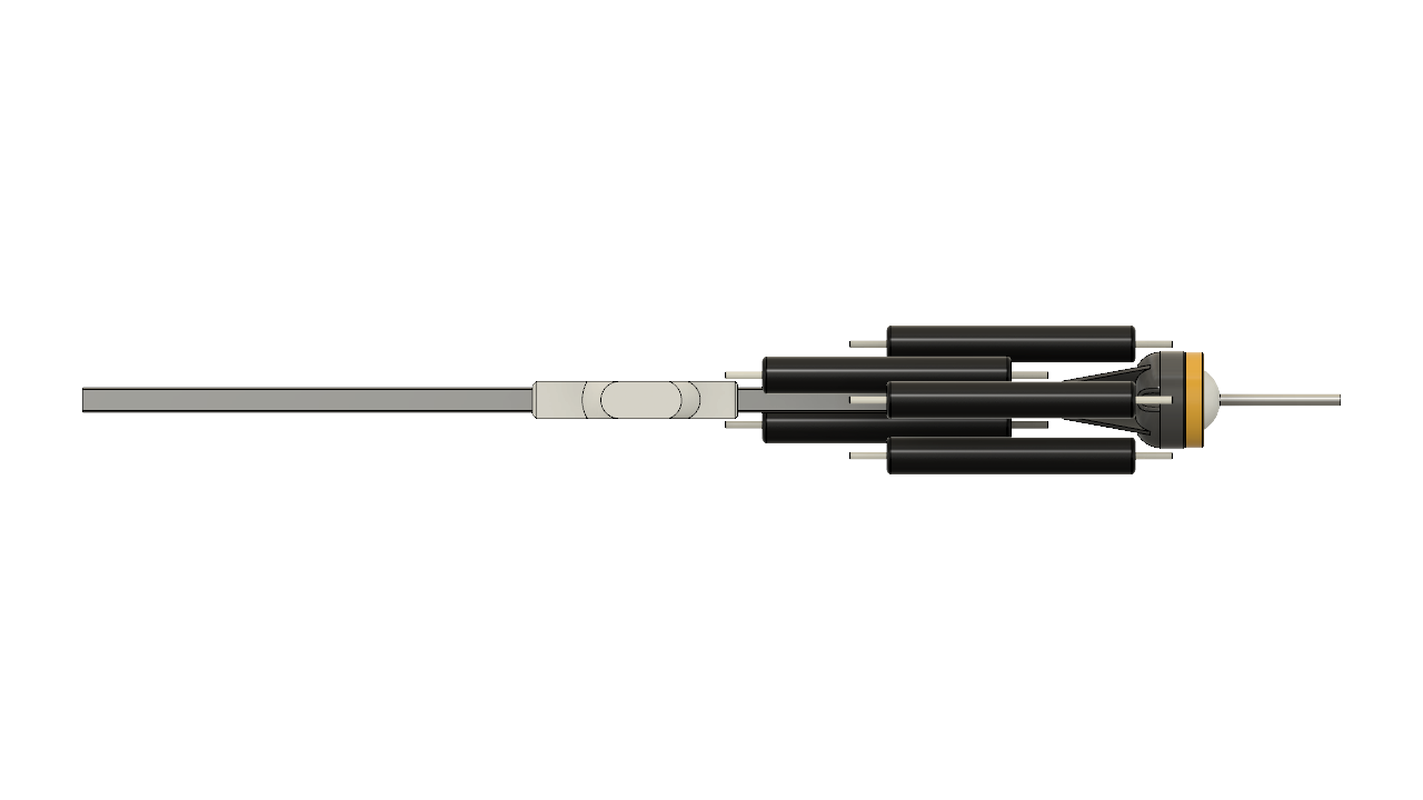
Head pitch, roll and yaw mechanism
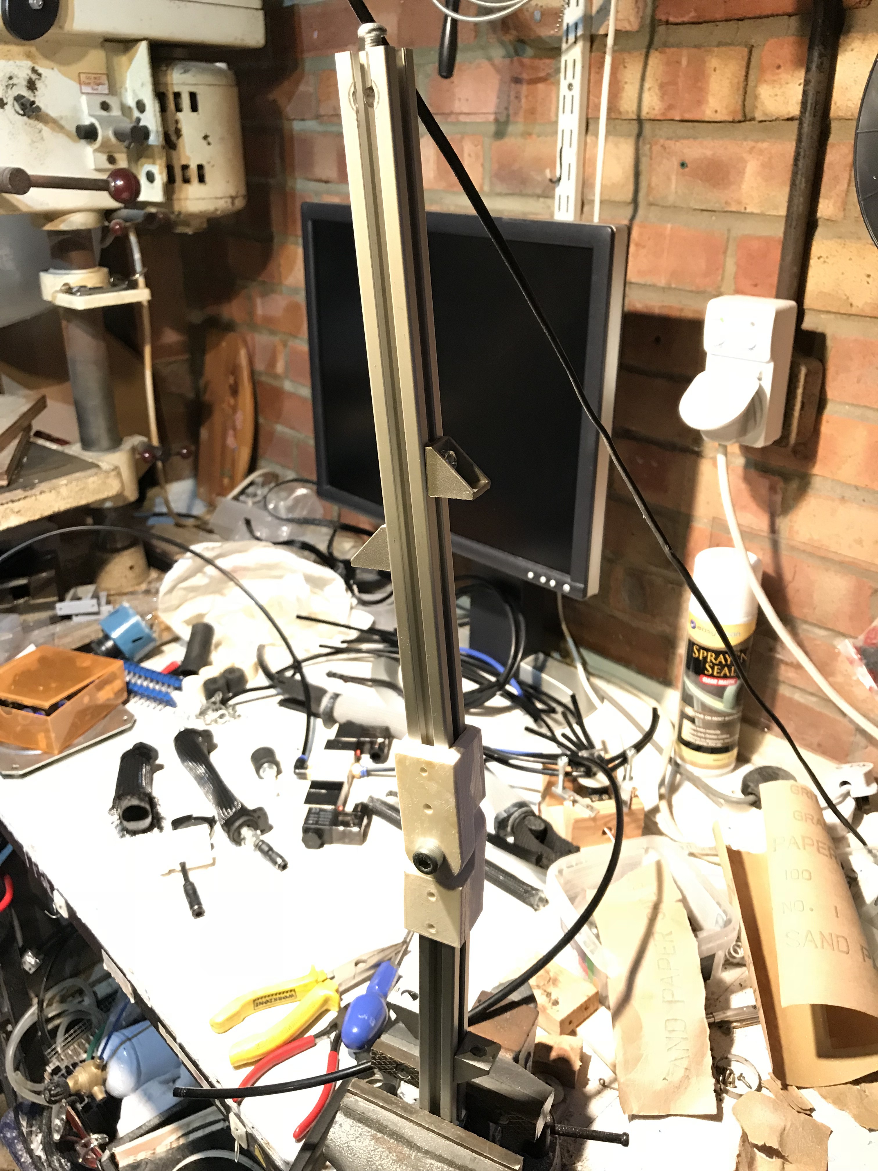
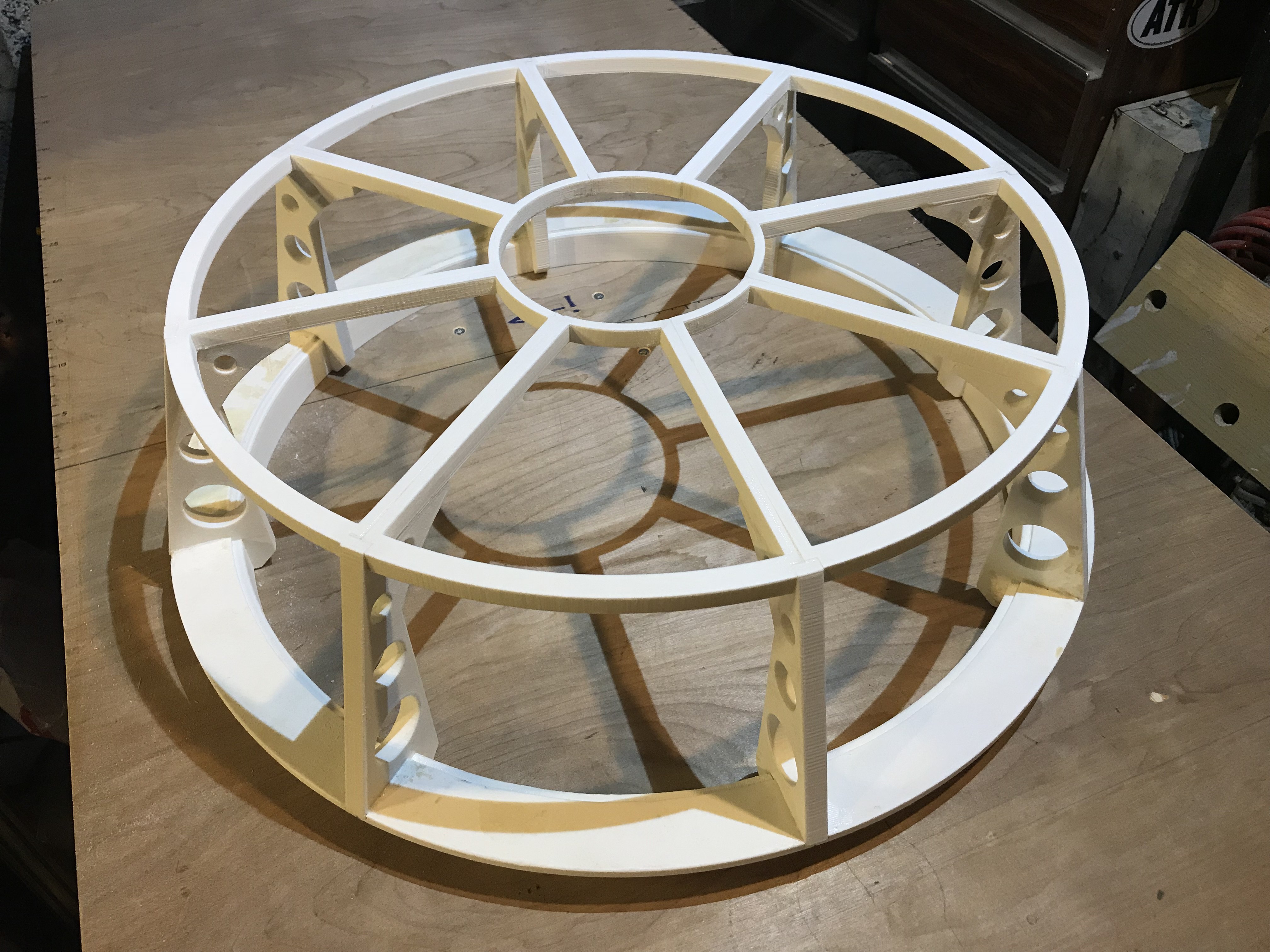
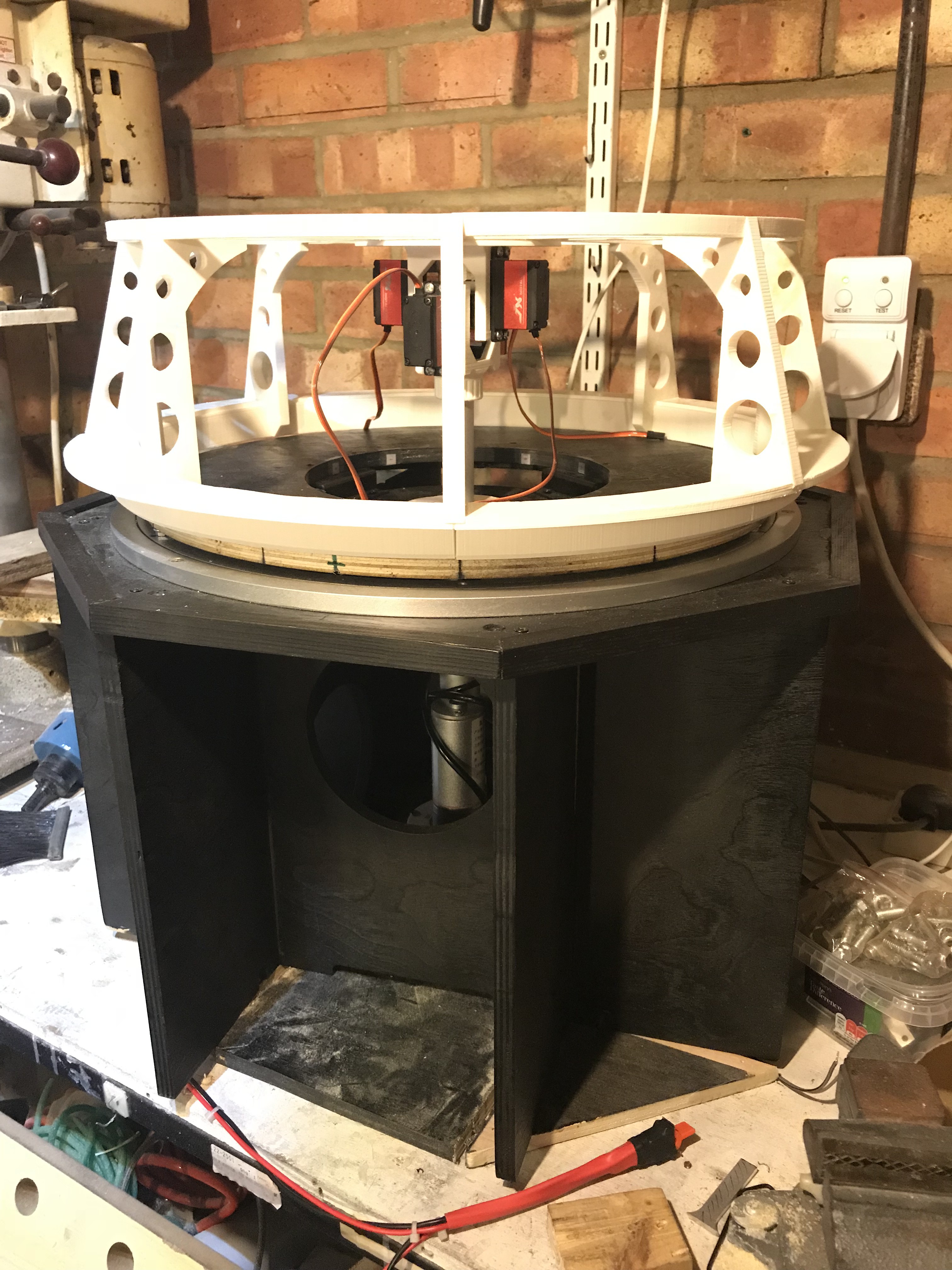
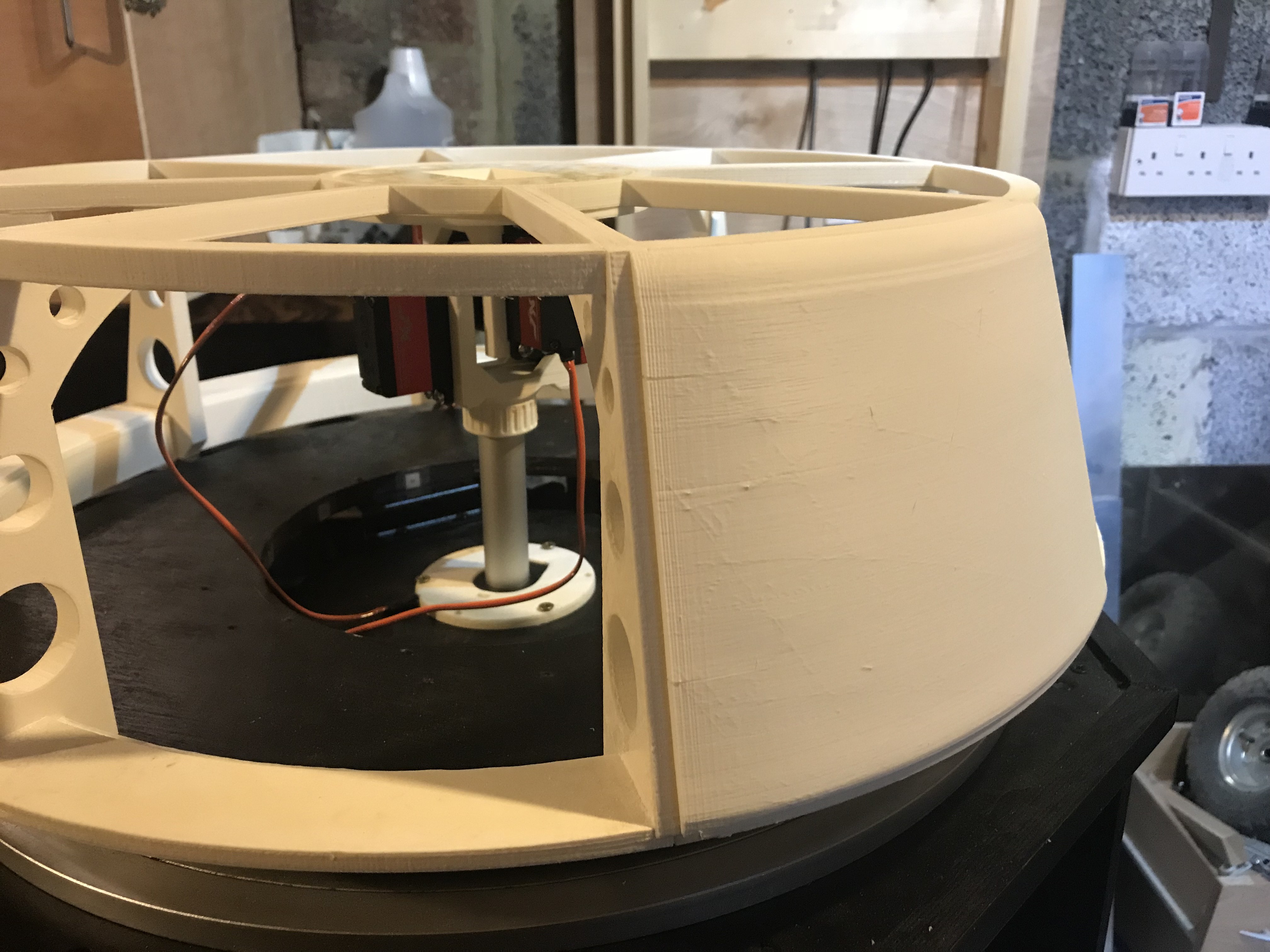
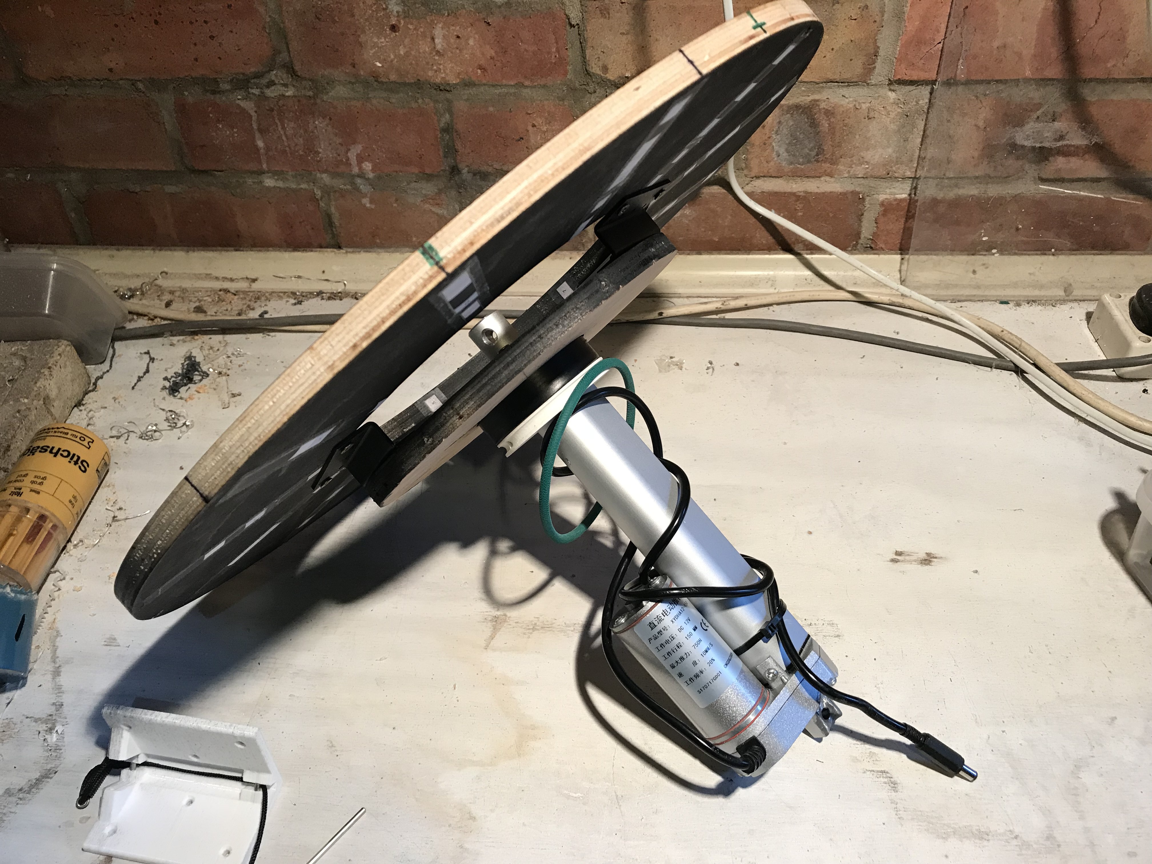
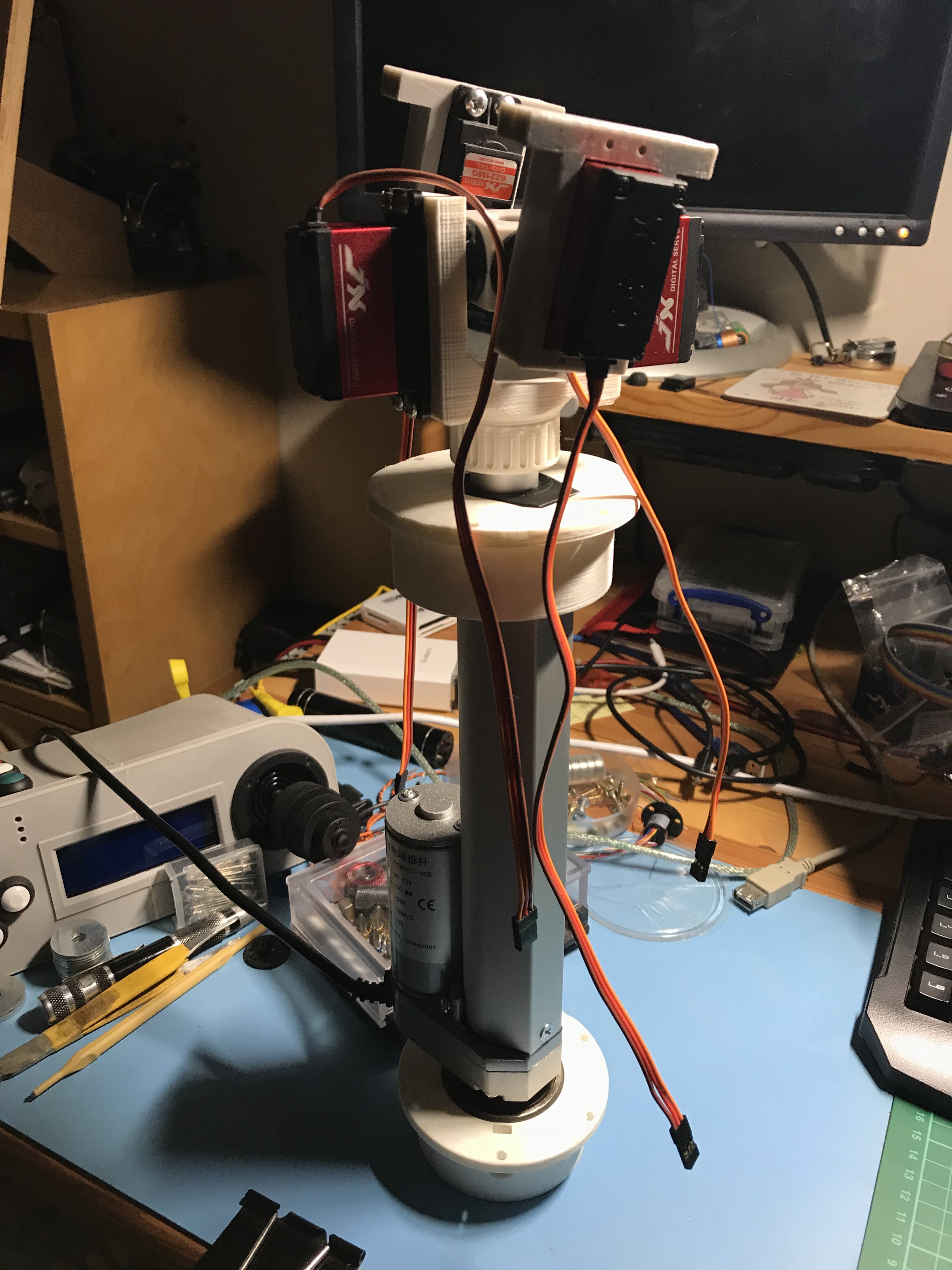
03/08/2018 at 08:08 • 0 commentsI've just assembled the new head mechanism and I'm quite pleased with it!
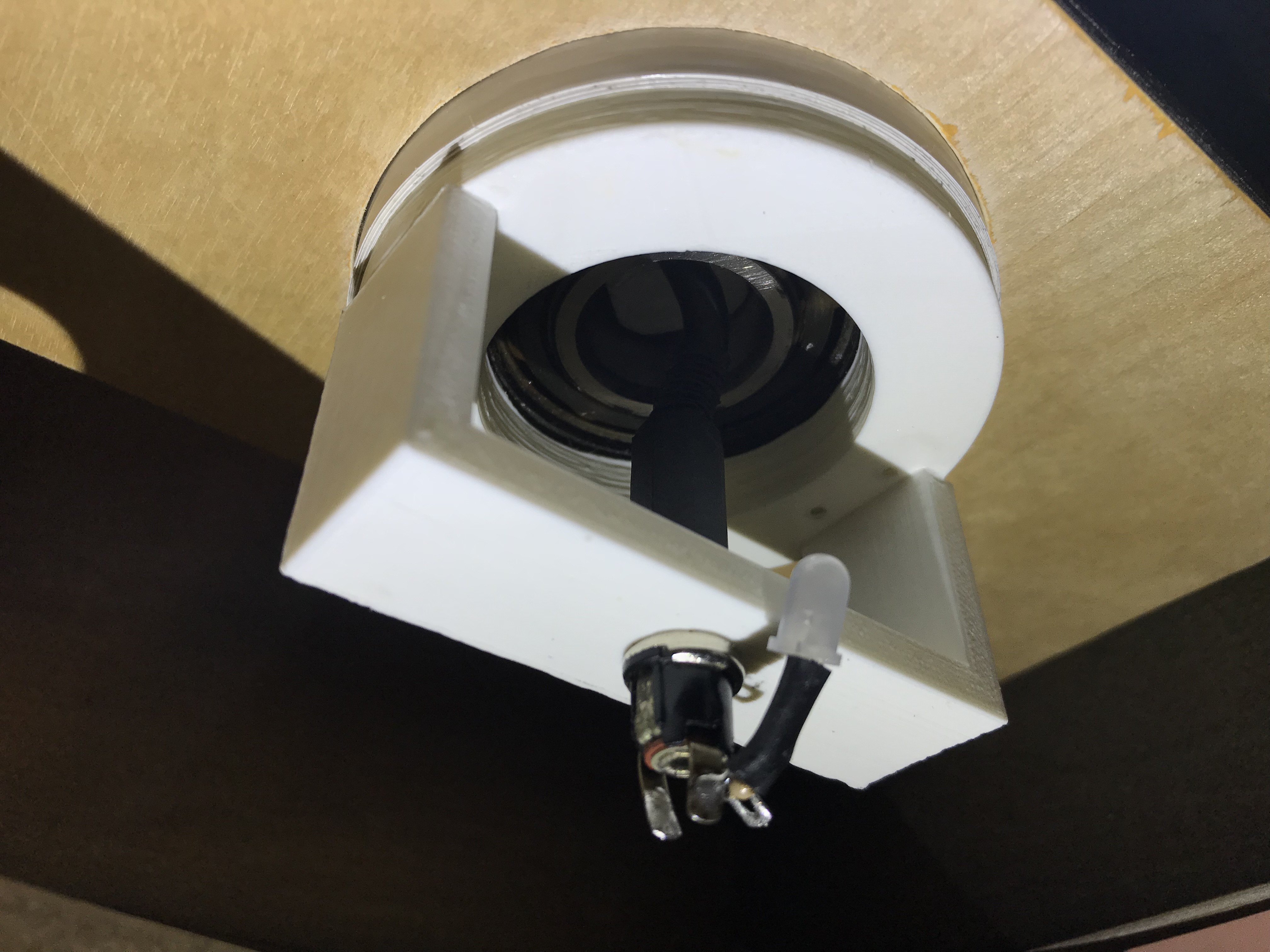
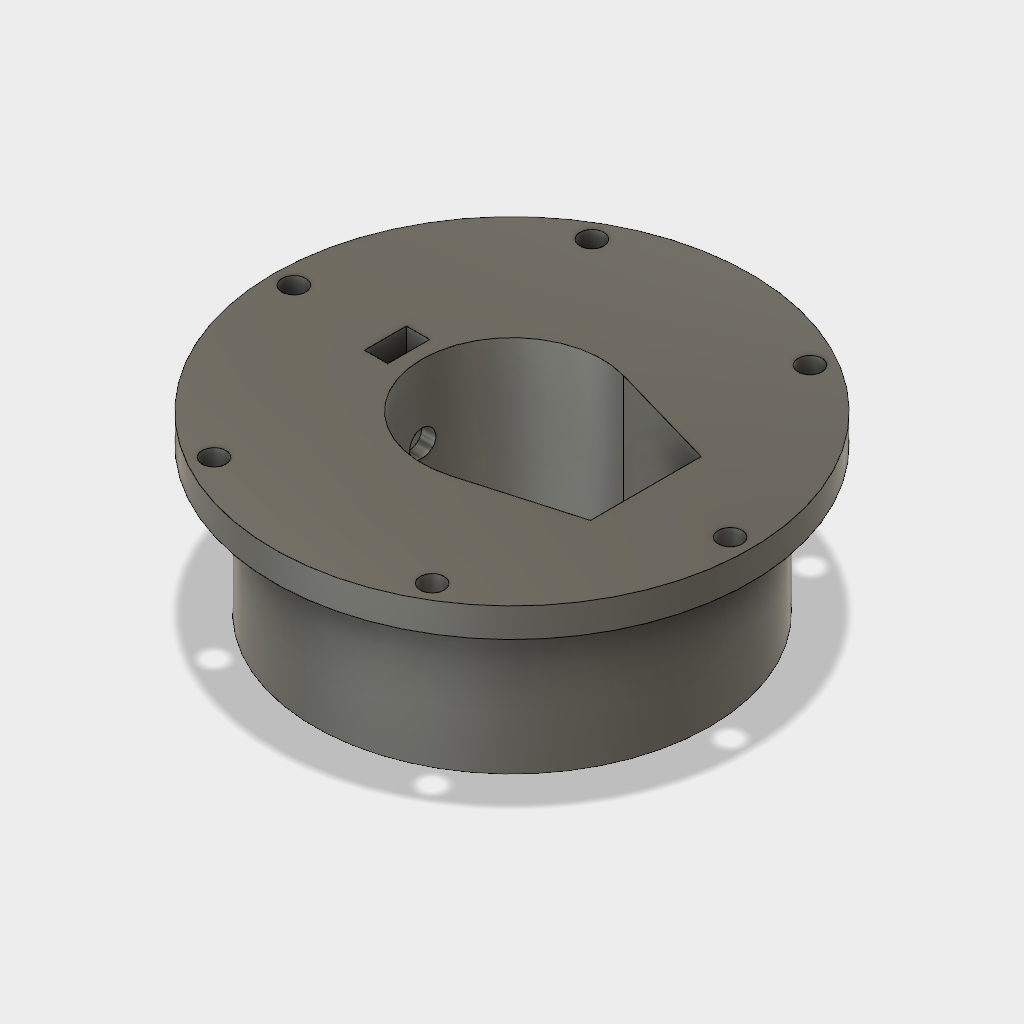
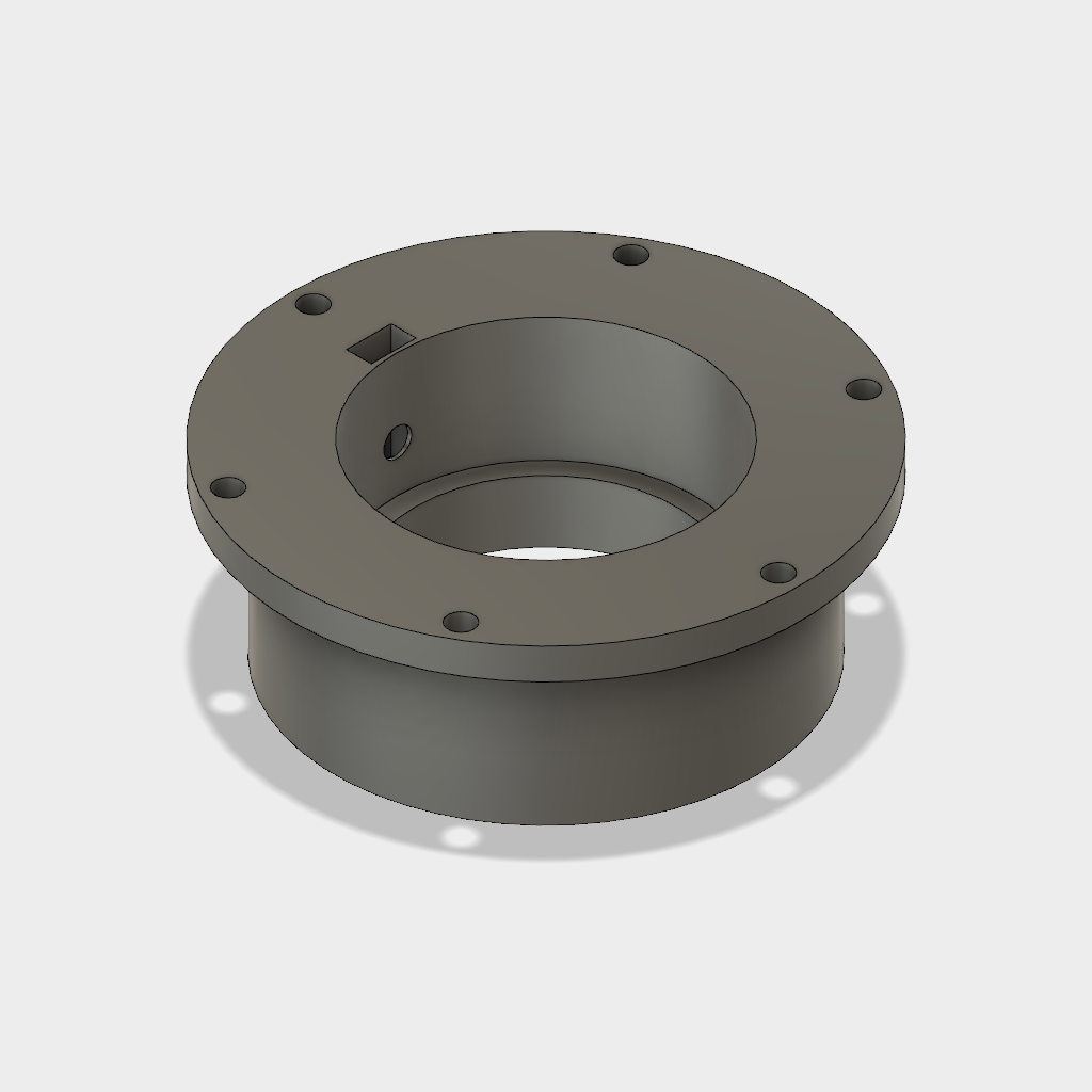
The assembly will allow the head to pitch and roll in order to stay level in response to external disturbances (terrain mostly). I want a level head for mounting sensors and I think it'll look cool. There's a small slip-ring embedded in the center allowing 360° rotation via the gearhead motor clamped to the side. The whole thing sits on top of a linear actuator giving 150mm of vertical travel to provide clearance for pitch and roll but still allowing for a compact "stowed" mode.

Head pitch, roll & yaw mech.
I was happy to finally get this assembled as progress had been slow recently with a few hurdles to get over. My cheap 3D printer has not been liking the cold either and spare time and money are of course major constraints, I guess they are for most people. -
A different approach
02/27/2018 at 10:46 • 5 commentsIn order to help me decide on whether to proceed with PAMs or switch to motors, I made a crude model of a leg. It's difficult to see here but there's 4 PAMs for the hip (up/down & left/right) and 2 PAMs for the knee. The paracord "tendons" that attach to the muscles are not shown. The knee joint has a small drum built-in for the paracord to wrap around, to give (in theory) 180° of travel based on ~30mm of PAM stroke.
![]()
PAM actuated leg concept - hip & knee ![]()
Knee joint with drum for 2020 profile ![]()
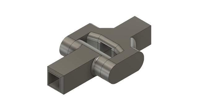
Ball joint for 2020 aluminium extrusion ![]()
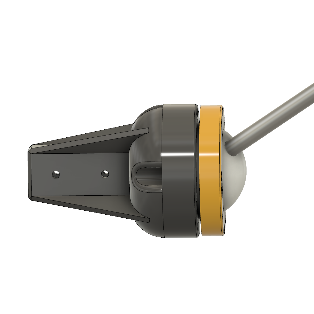
Training cue ball drilled, tapped and threaded onto M10 stud But I'm still not convinced. I've held off printing or buying any more parts until I can decide on which method I want to go with. I only buy enough of something to build a prototype and don't consider anything as wasted as I usually I learn something from it.
In parallel to the PAM/motor dilemma, I began to dislike the direction I was going in with the overall design finding it is too restricting and, currently lacking some lower-body structure to work on, I felt I'd been caught in a loop with it; PAM actuation would mean one type of leg mounting configuration and motors require another. The head-drive felt like a bodge too (and subsequently gave substandard performance) with little room to improvements. My early "hash" chassis was becoming a hindrance. So I had a re-think.
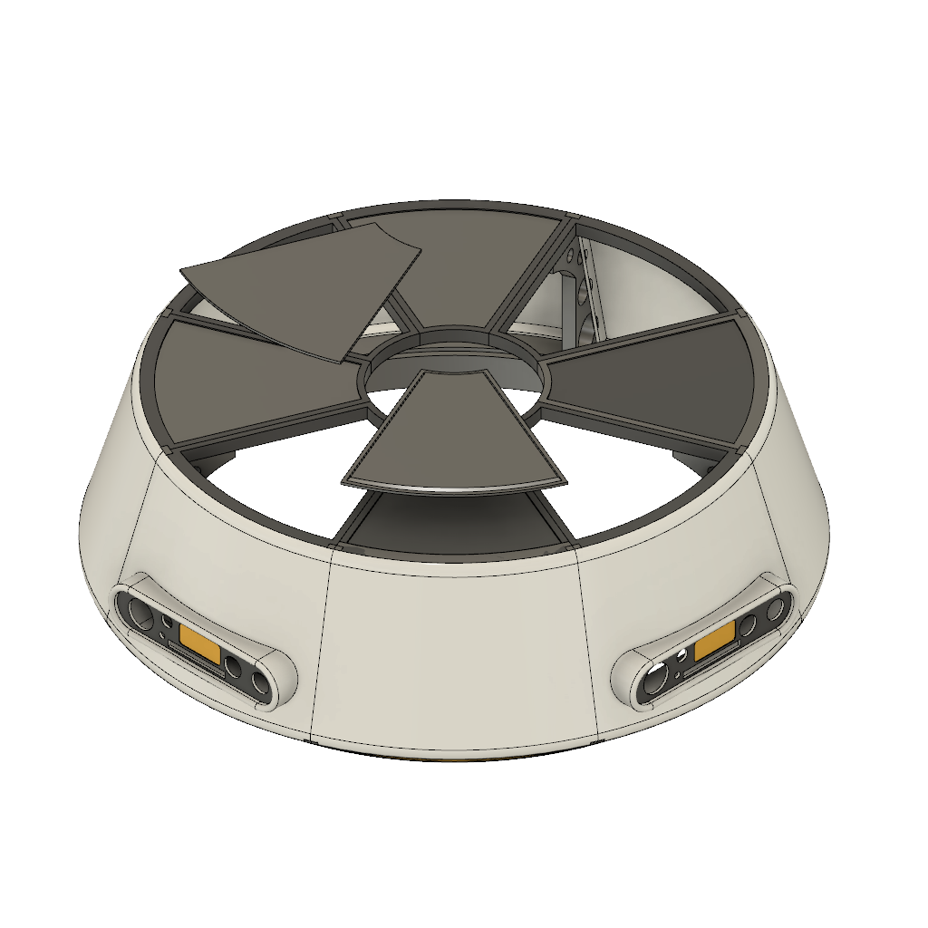
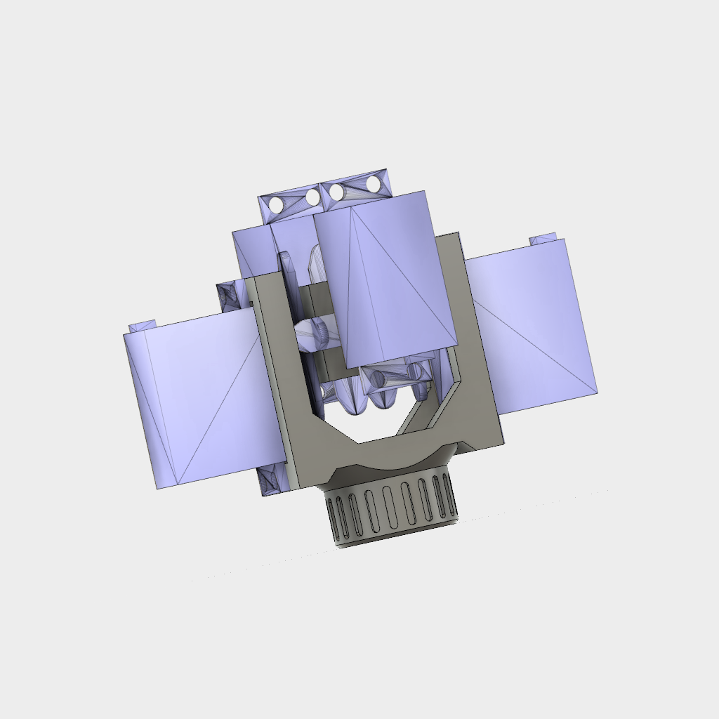
Below is crude model, just to get a feel for proportions, of an alternative chassis using 2020 profile. It will allow more freedom to adjust things and, more importantly, give me some lower-body structure to work on. The head will still be able to pitch, roll, yaw and move in the Z axis via the existing pitch/roll mechanism and linear actuator (not shown), though the yaw drive will probably move to the end of the linear actuator rather than turn the whole thing as I do currently.
![]()
New approach to chassis using 2020 profile to give more space for legs and radically different appearance when unfolded. If using PAMs, the mounts for the hip ball-joints would be tilted back to allow the legs to fold against/into the body. They may have to be actuated too in order to achieve the desired range. PAMs aren't going to cut it if I have to add extra motors to work-around their shortcomings.
I intend to have panels and the shape of the leg themselves give a more closed cylindrical look when folded up but a completely different look when opened out. I feel that I'll have more room for additional appendages too.
Motors
The more I learn about BLDC motors the more I'm favouring them. I was unsure if I could easily get a high enough current ESC that has an equal reverse speed but it seems they are available, if I understand correctly it's the calibration/setup that determines min/max scaling for forward and reverse. I have also looked at VESC and ODrive but aside from availability issues, they are both quite an investment just to try, so I'll need to be sure.
Looking at Hobbyking outrunner BLDCs:
57g £9.23 7A 75W 3S KEDA 28-30 920KV Outrunner (purchased)
153g £16.28 28A 450W 3-4S KEDA 36-48 1030Kv Outrunner 4S
291g £24.36 37A 600W 3-4S KEDA 49-55 750Kv Outrunner 4S
290g £19.84 65A 1300W 5-6S KEDA 43-62 1650Kv Outrunner 6S
390g £29.61 50A 1300W 5-6S KEDA 49-64 330Kv Outrunner 6S
500g £29.61 80A 1500W 5-6S KEDA 56-63 195KV Outrunner 6S
670g £36.48 90A 2000W KEDA 63-64 190KV Outrunner 10S
275g £36.45 58A 1260W 5-7S Turnigy Aerodrive SK3-5045-450KV
376g £37.49 65A 1630W 6-10S Turnigy Aerodrive SK3-5055-320KV
369g £39.37 60A 1510W 6-10S Turnigy Aerodrive SK3-5055-280KV
531g £45.44 65A 2050W 6-10s Turnigy Aerodrive SK3-5065-275KV
530g £45.53 60A 1850W 10S Turnigy Aerodrive SK3-5065-236KV
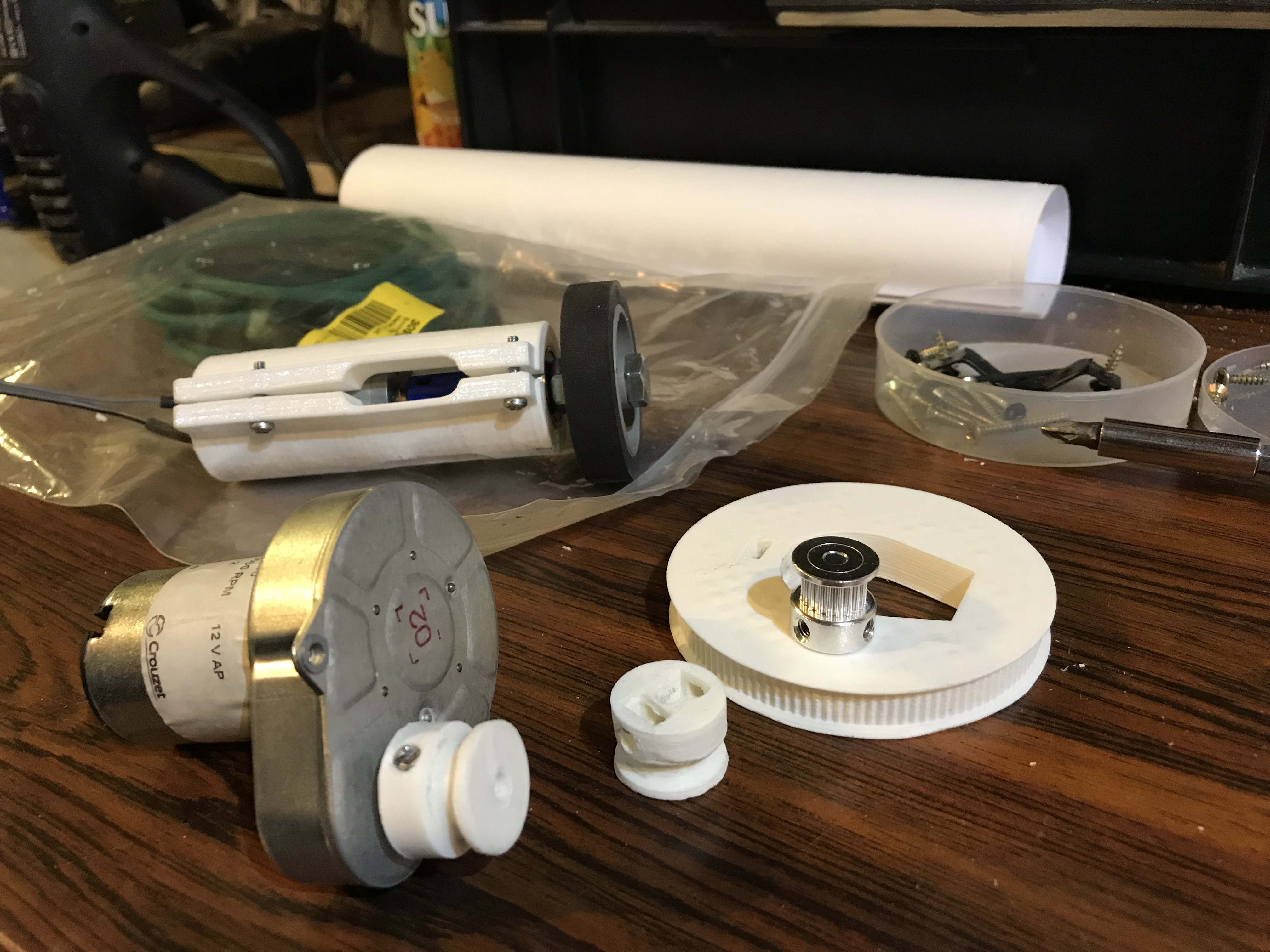
In looking at a selection of motors and watching some BLDC motors in use in a number of YouTube videos, I'm trying to understand what I need. I've also played some more with a small motor that I bought months ago.
PAMs are becoming less attractive
- Short stroke, desired range of motion difficult without torque reduction/speed increase. Would still need additional actuators to properly fold legs.
- Non-linear force, max when extended (relaxed/start).
- Non-locking.
- Compliant (difficult to position).
- Volume/mass of compressor(s) (~3kg each), reservoir(s) (<1kg with plastic bottles) and valves (>400g per DOF). 400g x 12 (at least) + 3kg = 7.8kg
- Muscle construction variations.+ Compliant (suspension).
+ Can be slowed with flow restriction. Regulator/valve cost, size, weight?And I think I have a workable solution for the main hip actuation that is within my ability to produce, so I've pretty much decided on motors!
-
Am I fooling myself?
02/08/2018 at 18:49 • 0 commentsDo PAMs really have much benefit over motors?
Some (subjective) pros & cons of PAMs vs BLDC motors for this application:
Pneumatic Artificial Muscles Motors (& gearbox) + Powerful for their weight/cost.
+ Fast.- Have to trade speed for torque.
- Do I have the budget for big enough motors?+ Negligible weight for muscle itself.
- Weight of valves (400g each) & compressor (2.88kg). Reservoirs planned to be 2L soft drinks bottles (tested to 90psi).
- Fittings, pressure sensors, regulator (all non-zero).- Weight of motors & gearboxes or lead-screws. Small KEDA 28-30 920KV Brushless Outrunner weighs in at 57g.
Larger Turnigy Aerodrive SK3 - 5055-280KV Brushless Outrunner: 570g.+ Inexpensive, even including cost of 3-way solenoid valves. ~£11 per DOF.
+ Single small compressor (85lpm) for ~£30.
- Fittings & accessories should be considered (all non-zero).+ Small BLDC motor ~£9
- Larger (more torque) motors cost more. £40+ for bigger BLDCs.
- Required ESCs can be costly too(?)+ Compliant: built-in suspension for both rolling and walking.
+ A degree of safety around those pesky humans.
- Difficult to position and lack of rigidity would make balancing (future!) more difficult.
- Limited unpowered support - collapses when not powered, so no static display or maintenance.+ Easier to position.
+ Gearing that isn't back-driveable would automatically lock limbs for static support.
- Could be too rigid? Transfer of shock. Not compliant to terrain.- Air demand could outstrip supply. Compressor choice & reservoir size have major impact.
- Compressor current ~30A.Current of multiple BLDC motors?
Small KEDA 28-30 920KV Outrunner max 7A.
Turnigy Aerodrive SK3 - 5055-280KV max 60A.I'm concerned about the speed-torque trade-off with motors; I guess that's solved with bigger motors but that has weight and cost implications. PAMs seem to have plenty of power but I'm fairly sure I'd be shortening the life-span of the solenoid valves by operating them at high rates and it would be a huge PITA to have to switch to motors, because of reliability issues, once I'd committed to PAMs.
Maybe a hybrid system? Best of both worlds or twice the weight, power consumption and complexity?
-
Successful PAM test!
02/07/2018 at 08:47 • 0 commentsMy first attempt at crude position control with pneumatic artificial muscles. Yes, there's overshoot and lag etc, but I'm pleased I achieved this with basically just a comparator with some deadband, no PID (yet).
With better mechanical mounts for the PAMs and a different feedback sensor, I should be able to get tighter performance with software. But as a proof of concept; I'm happy! It may be a go for PAMs on DB-T7!
Raw video below because I'm too busy/lazy to make it fancy. Enjoy!
-
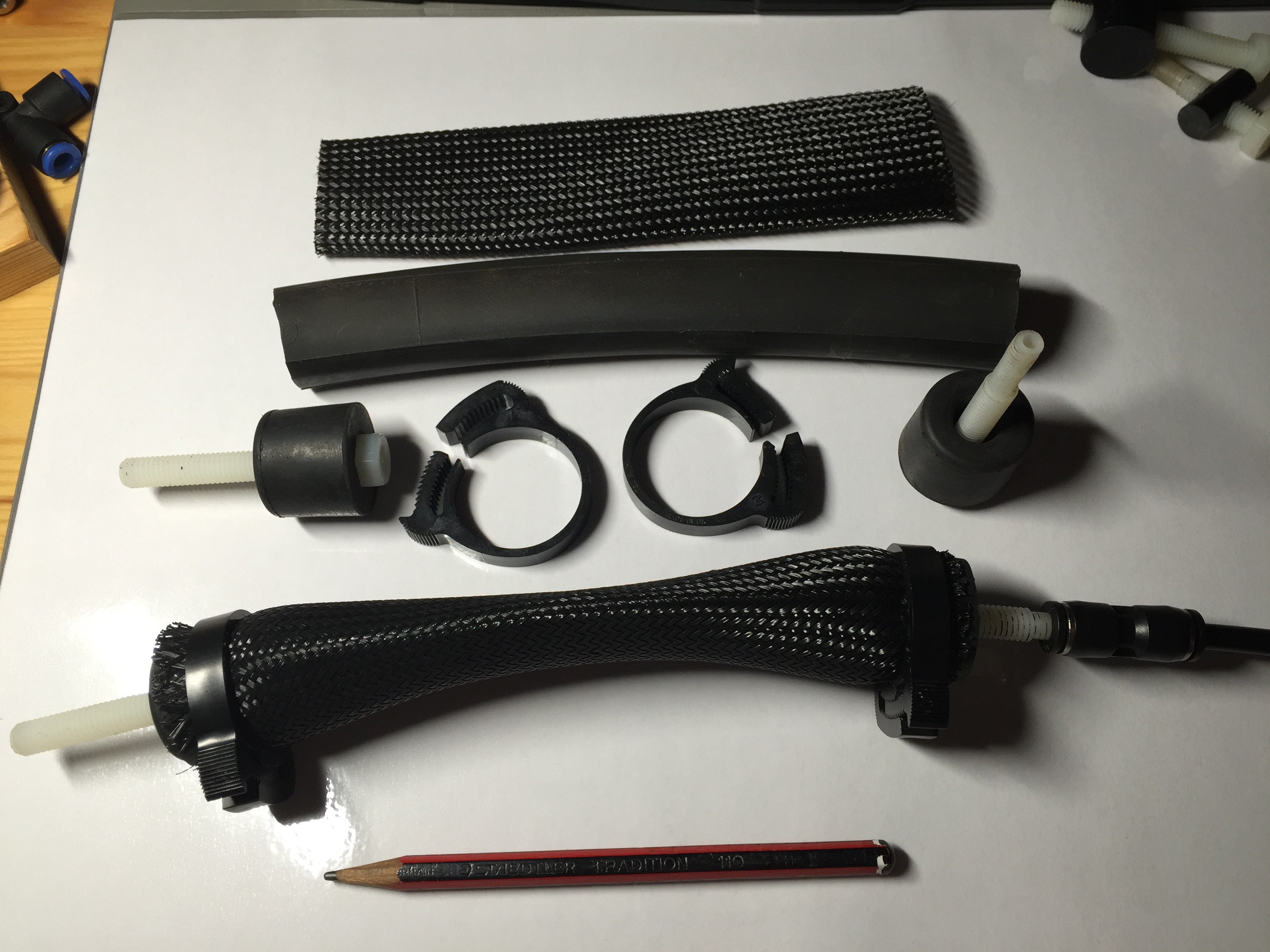
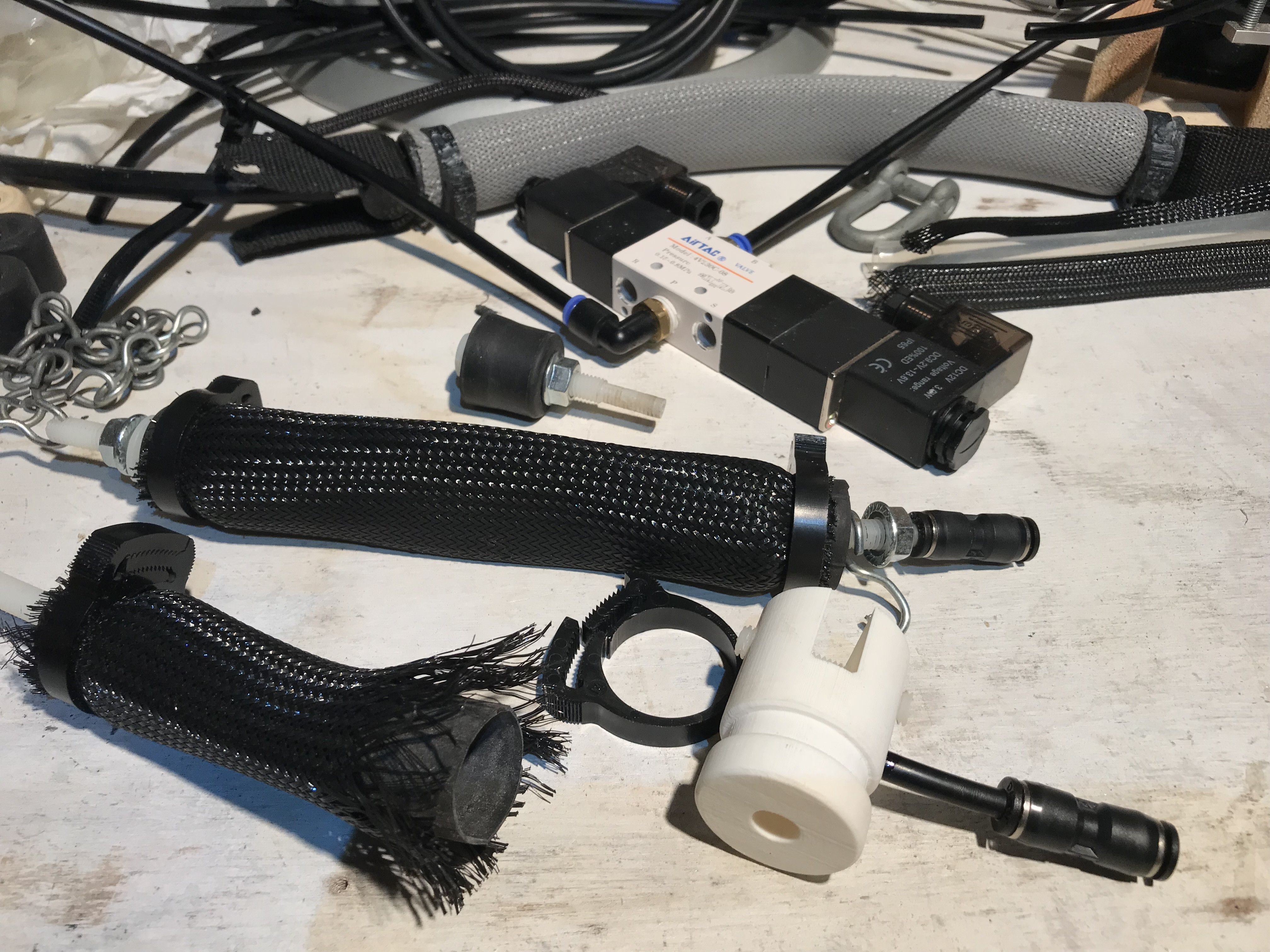
Pneumatic Artificial Muscle (PAM) testing
01/28/2018 at 22:36 • 1 commentI’ve been playing with DIY air muscles on and off since 2007 and I'm contemplating using them on Droidbot-thingy, providing I'll be able to control them satisfactorily. I know they're strong and can be parallelled to further increase their pulling power but are they controllable enough for this application (super precision not needed)?
BLDC motors and 3D printed gearboxes are the main alternative. Air muscles are cheap, easy, light, fast and powerful but are difficult to control and have limited stroke (difficult to get a limb to fold back on itself), whereas motors are great for positioning, easy(ish) to control and can have a limb fold up on itself with no problems. However in order to get enough torque, the gearbox must provide sufficient reduction but this comes at the cost of speed; I could have a super strong robot, a SLOW super strong robot. The gearbox is the complex bit and potentially costly. High torque gearhead motors are expensive and I need a lot of them. And I'm tight.![]()
My DIY PAM ![]()
Quick test rig So I keep coming back to PAMs, at least until I convince myself there's a better way. The rig was just a quick lash-up to get a feel for the PAM performance as an opposing pair on a simple single-jointed limb. I know from experience that air muscles have a massive strength-to-weight ratio but I've never before got to the stage of testing for control, mainly because I had focused on the design of a cheap DIY proportional valve that would work at 100psi - it worked, but I didn't like it; too messy. Maybe now I could 3D print an improvement. Anyway, the muscles are directly fixed either side of the joint (containing a pair of skate bearings) without any additional pulleys (yet) and their mounts don't allow for proper articulation, but it'll do.
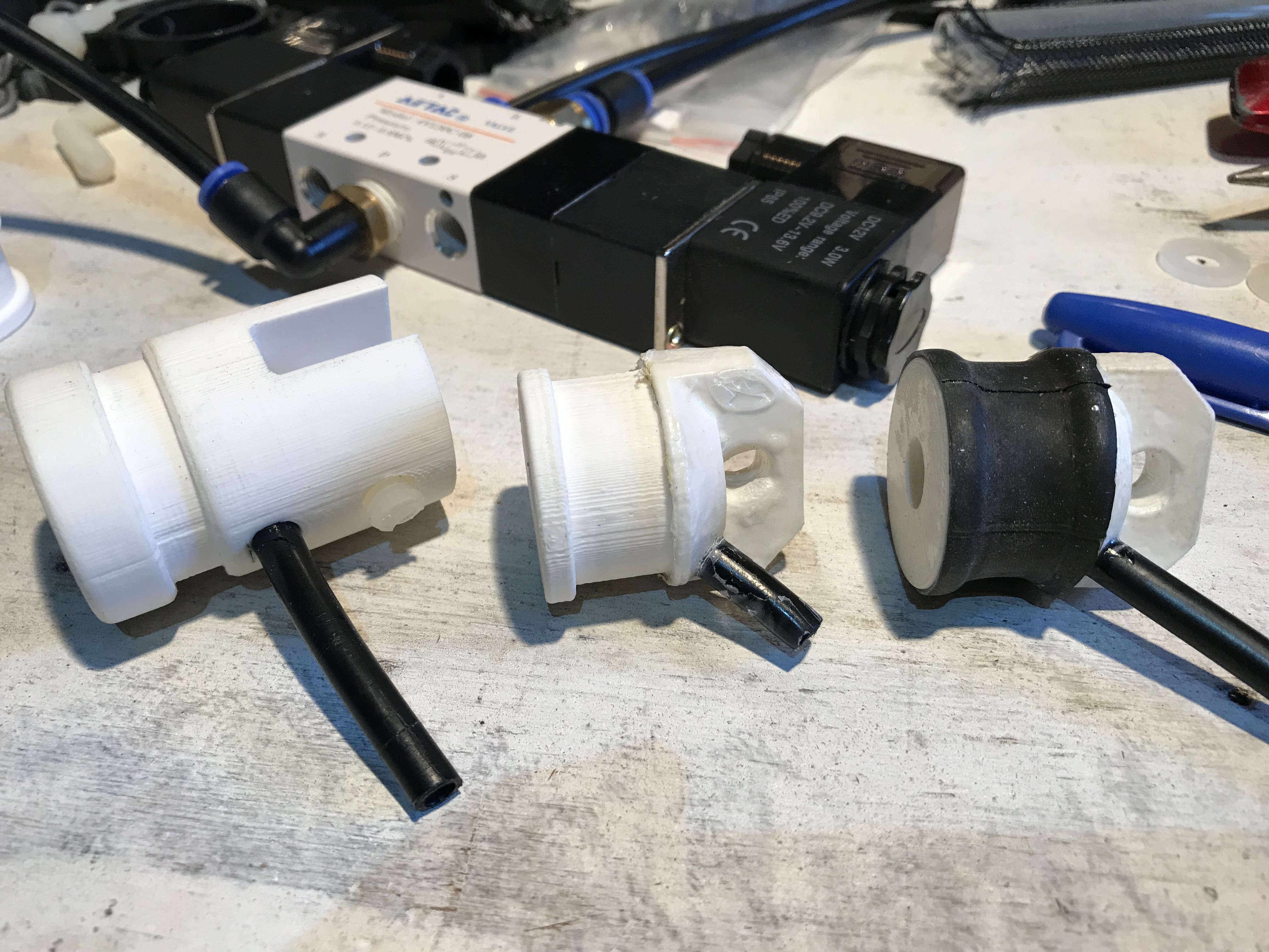
I've popped plenty of air muscles in the past and today wasn't any different. I was trying a 3D printed end cap to see if it would have any advantages (save me having to process the nylon bolts) but I was seeing a lot of leaking, before the pop.
![]()
End caps pop out if not clamped tightly enough ![]()
Tweaking the design
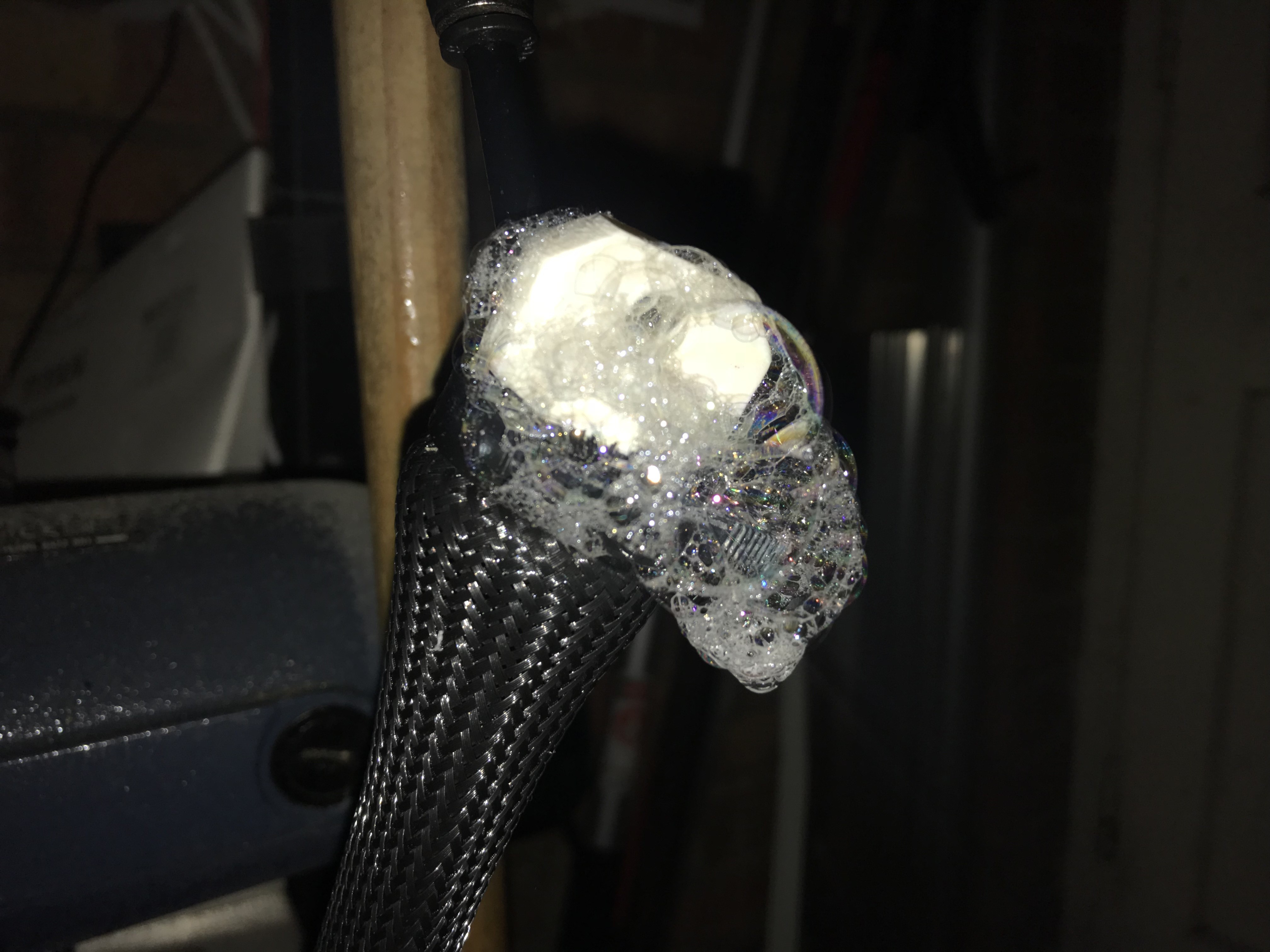
The second cap in the above photo was printed laying flat so build lines run top to bottom for mechanical strength, but it still leaked. I tried dipping it in ABS slurry to seal it, but the improvement was marginal. The third one was printed upright. It leaked. I tried the slurry sealing again. Nope. I tried and extra layer of rubber under the bladder... I had to admit it wasn't looking good.![]()
Just not up to it. Soapy water reveals air leaking from the cap itself I had been using plastic ratcheting hose clamps as they are lighter than the normal metal worm-drive type. Though I preferred the appearance and weight of the plastic clamps, they are pain to remove for repairs and I had to switch to standard ones in order to get the required clamping force and stop the braid and bladder pulling out under load. I was also hoping it would magically fix all the leaks.
Of course I could print the cap at 100% infill but it would take over 3hrs with no guarantee it would be any better and that kind of defeated the point. I resolved to improve the existing mounts (I broke one with a high side load) with thicker M10 nylon bolts, but right now I wanted to test a pair on a limb. Raw vids below.
Next I'll attempt to add some crude position control to help me with the PAM or motor and gearbox question.
If anyone has any input, I'm all ears.
-
Head progress
01/25/2018 at 19:08 • 0 commentsThe head skeleton is pretty much done. But I'm not sure exactly which sensors I'll be using or how I'm going to mount them, so that's been delaying things a little bit.
![]()
Still has an Astromech feel to it, I think. ![]()
I need to adjust the final height of the linear actuator to match with the parked position of the head. It won't be fully extended is use; just enough to allow for pitch and roll. It will only be extended fully for access.
![]()
A thin 3DP test panel that clips into place. All 3DP parts are in ABS so they can be solvent-welded together. Will obviously need filling and sanding before painting. I have had a few problems with the recent cold ambient temperatures and the 3D printer, nothing that can't be managed.
I've also setup Octoprint on a old Raspberry Pi with a webcam to keep an eye on prints, very handy!
![]()
Tweaking the design again. I have already decided against this scheme, but I'm still torn between 3DP panels and shaped aluminium panels or possibly a mixture of both.
-
Where's your head at?
01/03/2018 at 19:27 • 0 comments
Latest head design (after at least a dozen concepts). 
First ribs for head, in need of tidying. 
First segment (right) next to old design. My 3D printer stopped working just before Christmas and it took me a while to diagnose the root cause. It would get hot and extrude but not print when I tried a known-good file. A blocked nozzle was the original problem but very cold ambient temperatures and slipping feed drive had me disassembling the head numerous times. New nozzle and throat bolt (to be sure) and careful re-assembly had it back up and running by New Years Day (I know how to party!). Let the printing (re-)commence!

More parts awaiting prep. 
Head will house some of the sensors and processors. -
Getting in a spin
12/13/2017 at 23:24 • 0 commentsI had to strip the whole thing down to cut additional access holes in the chassis so I could reach inside to mount the GT2 belt on the pulley. After re-assembling and touching up the paint, I set about re-motorising the head. I was using a length of open GT2 belt rather than the closed-loop type, because it's what I had available. Unfortunately the necessary tension needed to avoid belt skipping was too much for my DIY joint and the belt kept breaking. I reprinted the pulleys but for 5mm round belt (I have some for my mini lathe) and that set-up almost worked but I couldn't easily get enough tension for the not inconsiderable weight and drag of the bearing and assembly. Time for Plan C: a bodged variant of the original direct-drive but with a smaller drive wheel and rigid mounting.
![]()
![]()
I also abandoned trying to use the small bearings to maintain electrical continuity for the head lift motor (linear actuator) and resorted back to a mini-DC barrel plug and socket mounted in a bridge under the bottom bearing. The static contact resistance of the bearings were a few hundred Ohms and varied wildly when turned. The bearings were only cheap Chinese ones though, better quality bearings may perform better. The DC jack resistance was a lot lower and more consistent and seems to work perfectly, for now at least.
![]()
Video!
I'm also trying out some new video editing software... and maybe I should get a microphone too.
-
Head actuation
10/18/2017 at 10:09 • 0 commentsOk, so I know what I'm doing for pitch and roll and I think I've got workable plan for lifting, but I'm still not sure how I'm now going to spin the whole assembly as I've moved away from the original drive (I was never 100% happy with it anyway).
So the new pitch-roll head design sits on top of a linear actuator which will itself be clamped vertically in the centre of the main chassis able to turn with the head bearing. The bottom has its own bearing and will be supported from the bottom of the chassis.
![]()
Pitch-Roll head ![]()
Top collar ![]()
Bottom collar One linear actuator, an old bearing from my motorbike headstock, some 20Kg/cm servos and some 3D printed parts...
![]()
Head pitch, roll and lift mechanism I'm really quite keen to get some fundamental motion happening with this. Going to need a fairly beefy slip-ring first though. I'm probably going to using some small bearings...
Droidbot 07 - Wheeled-Quadruped
An ambitious mobile robot for testing my skills and learning new ones.