Design and Manufacturing Principles
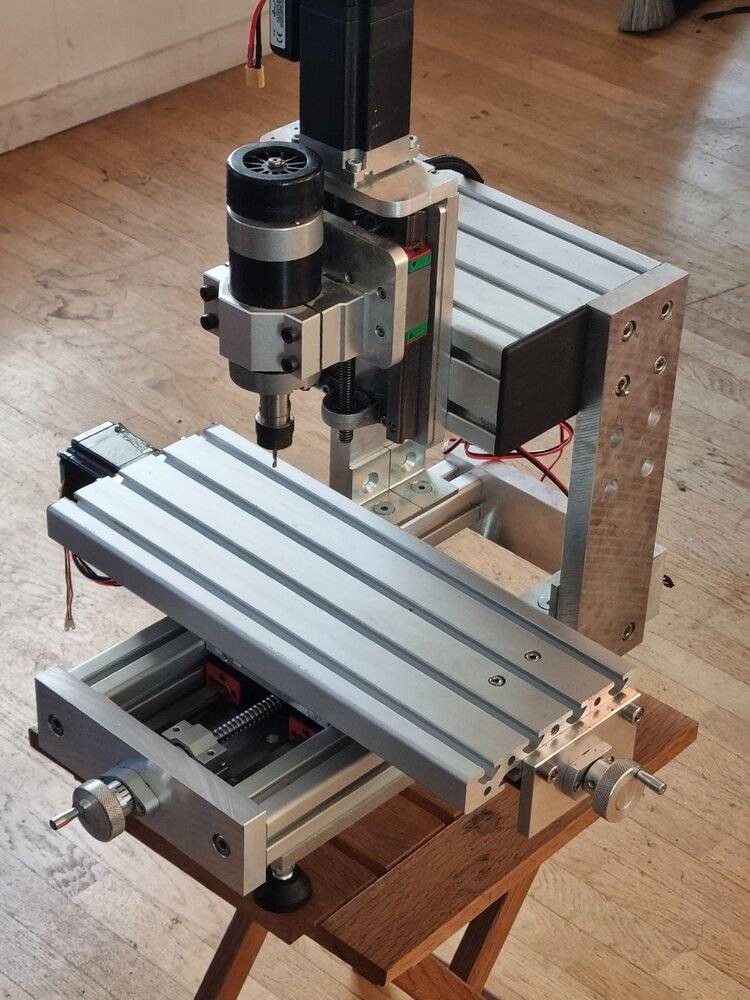
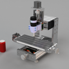
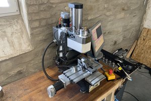
This machine was designed as a versatile tool capable of performing most small machining tasks typically encountered in a small amateur or professional workshop. It fits well in a compact workshop or laboratory.
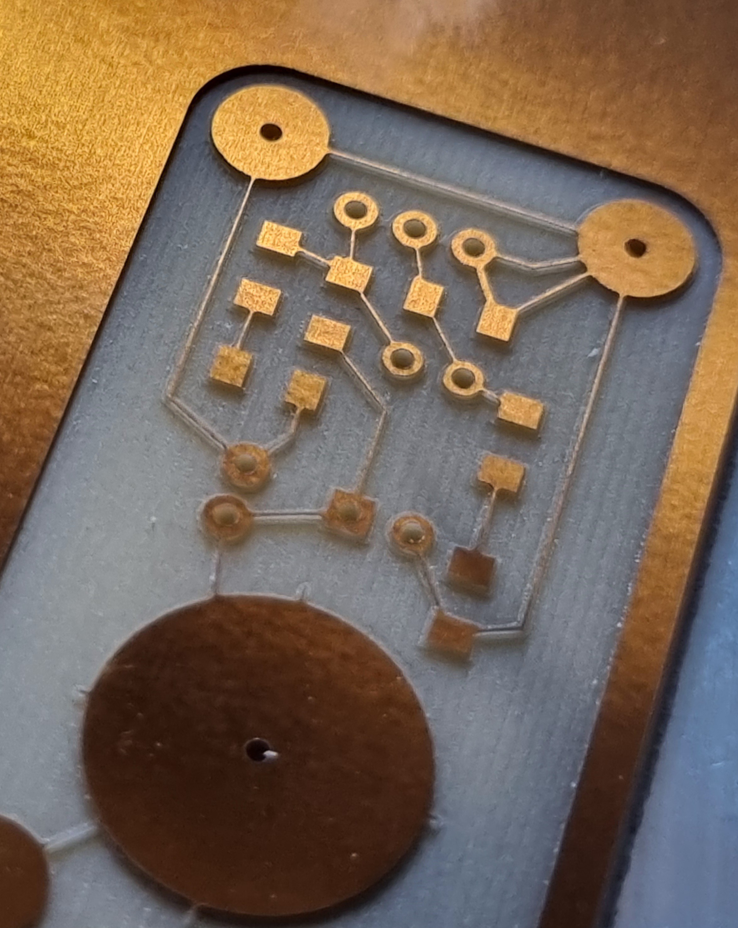 |
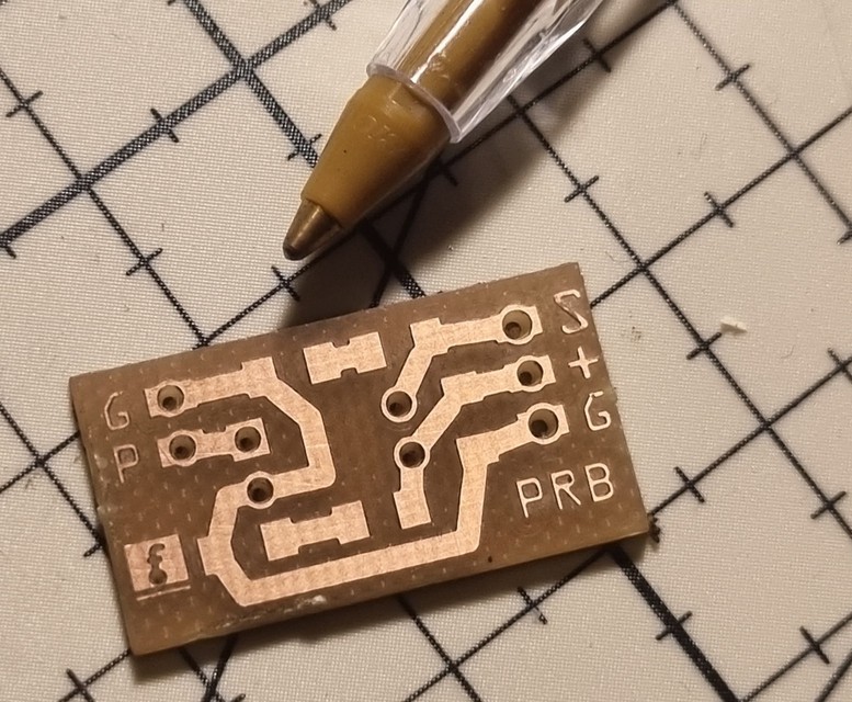 |
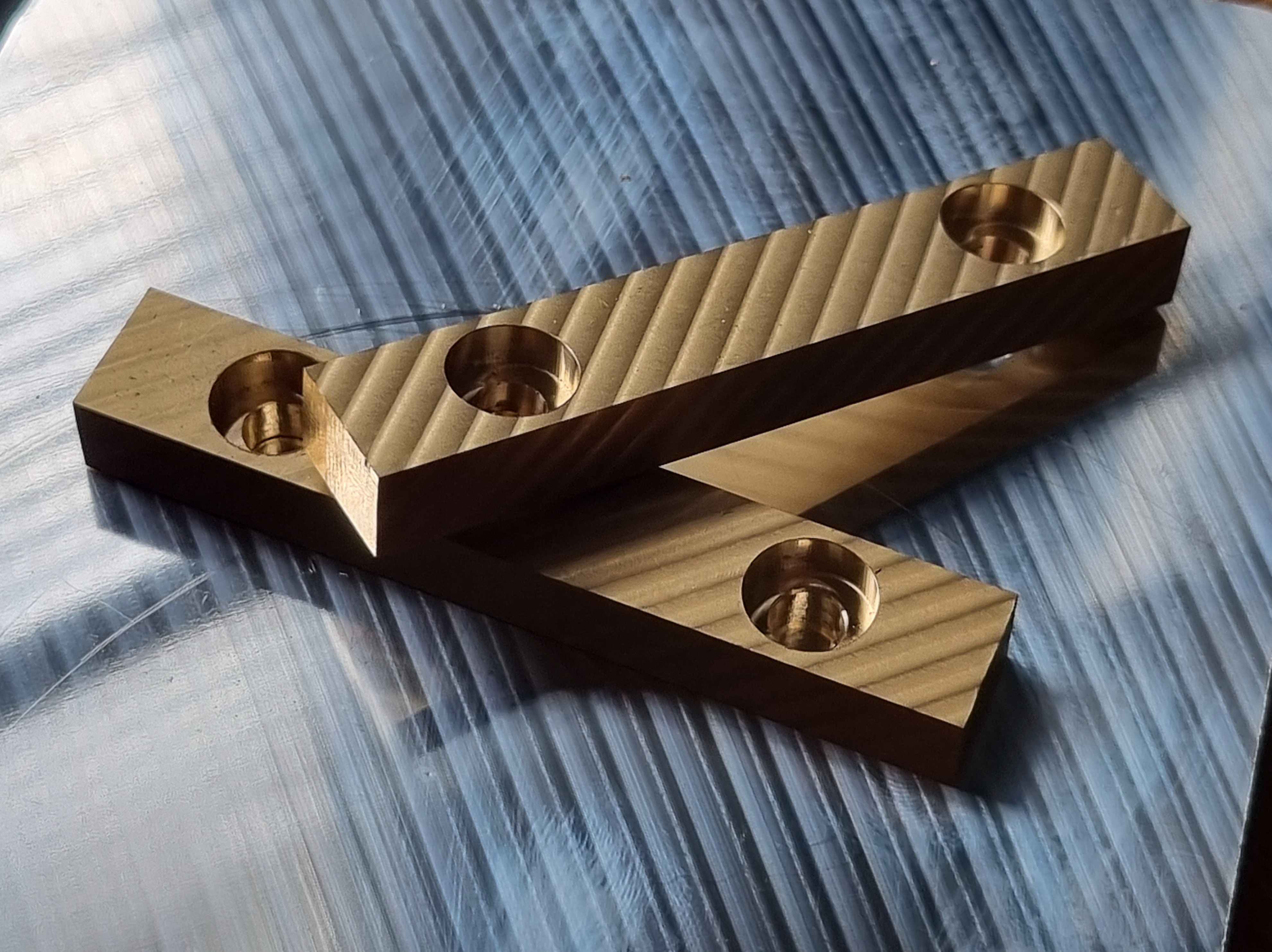 |
Structure and Kinematics
I opted against a router-style structure because it is less rigid and significantly harder to calibrate. The classic structure of conventional milling machines (XY+Z) offers several advantages compared to a router structure (Y+XZ). First, the X and Y axes are interconnected, making it much easier to adjust their perpendicularity. The X and Y rail planes are naturally parallel. Second, and more importantly, the classic structure has fewer degrees of freedom, meaning fewer adjustments are required.
Additionally, each adjustment affects only one axis at a time. On a router, adjusting the Y-axis can disrupt the Z-axis, making the calibration process more complex and requiring more tools.
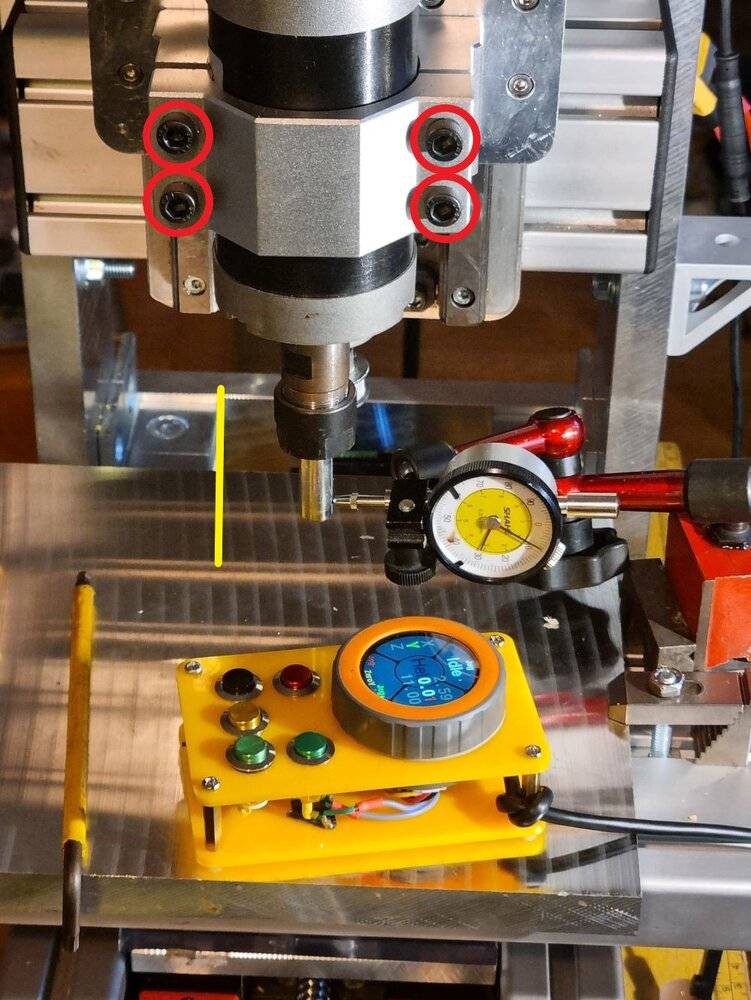
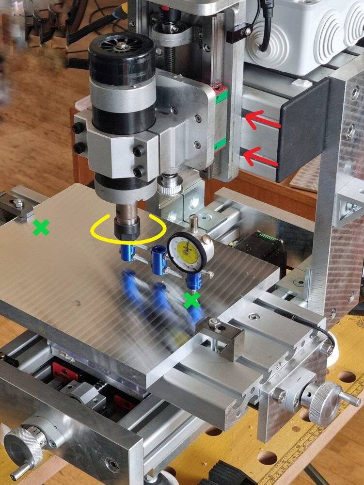
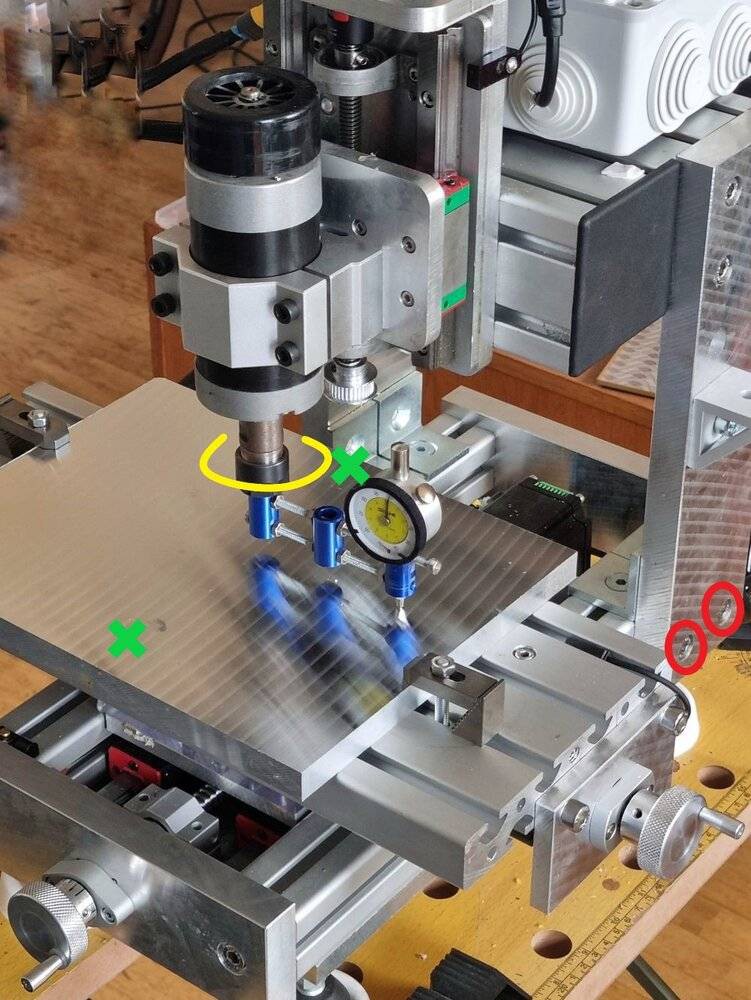
During the design phase, I focused on ensuring the machine could be finely and easily adjusted by following these principles:
- Minimize joints and the number of parts, avoiding components like angle brackets.
- Avoid thickness adjustments (e.g., no shims); all adjustments are rotational.
- Contact surfaces influencing kinematics are never machined surfaces, as no cutting process at my disposal guarantees perfect perpendicularity or parallelism.
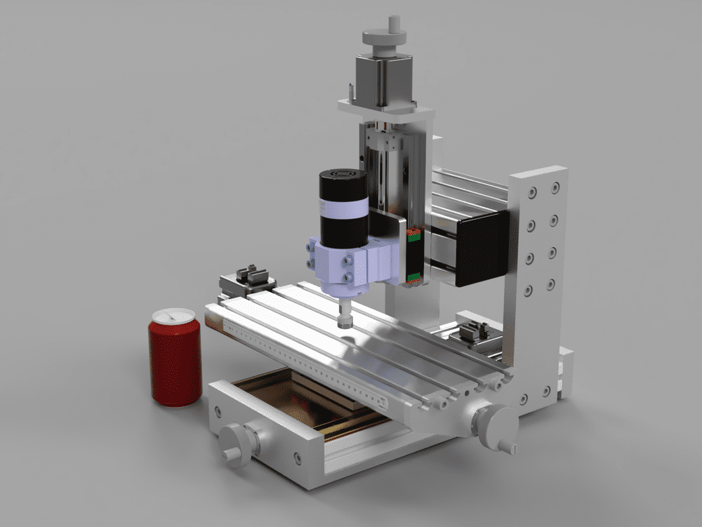
First version
Rigidity
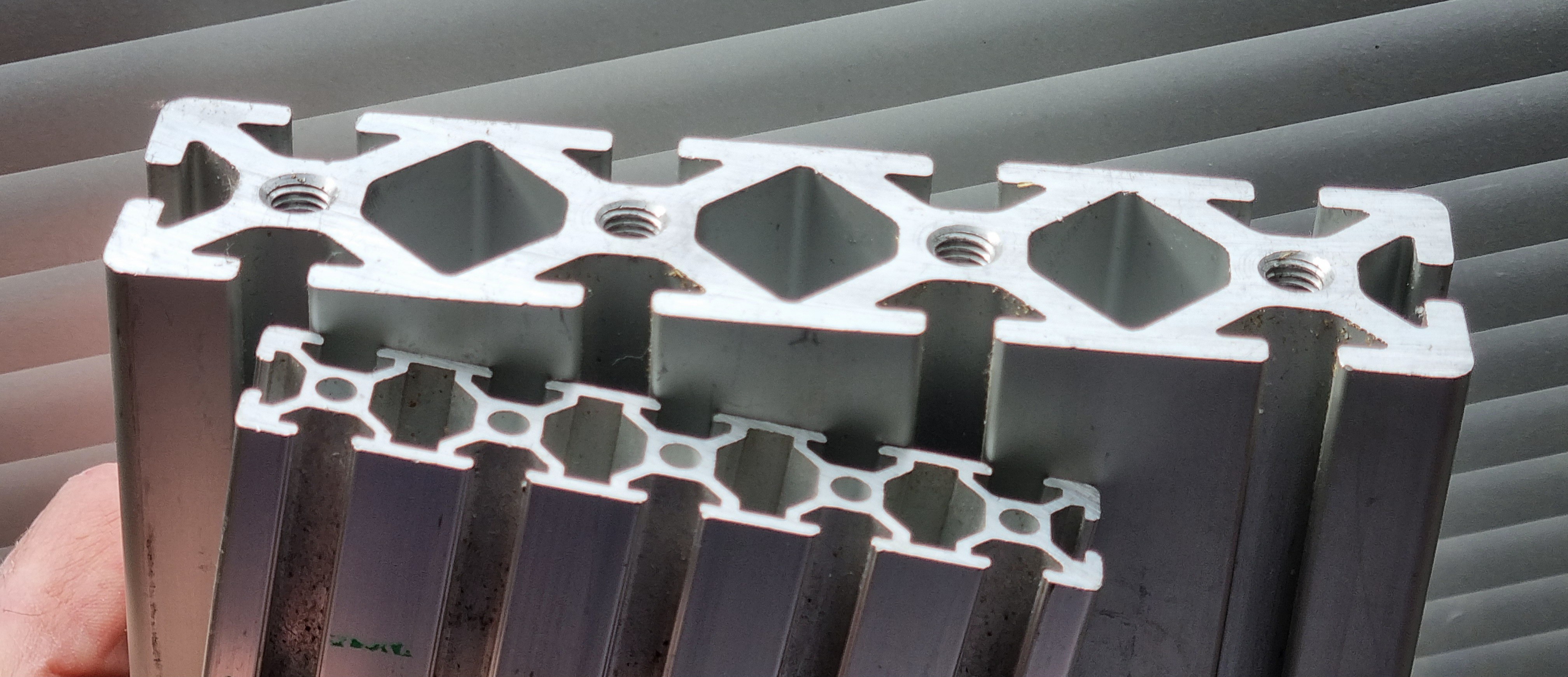
The entire structure is oversized for enhanced rigidity. I used 20mm-thick plates and heavy-duty aluminum profiles designed for structural applications. For instance, the head profile measures 80x160mm and weighs 2kg on its own. The entire structure is assembled using 8mm screws, allowing for secure clamping.
Detailed adjustment instructions will be provided.
Manufacturing
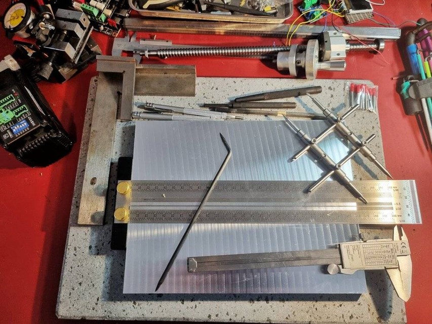
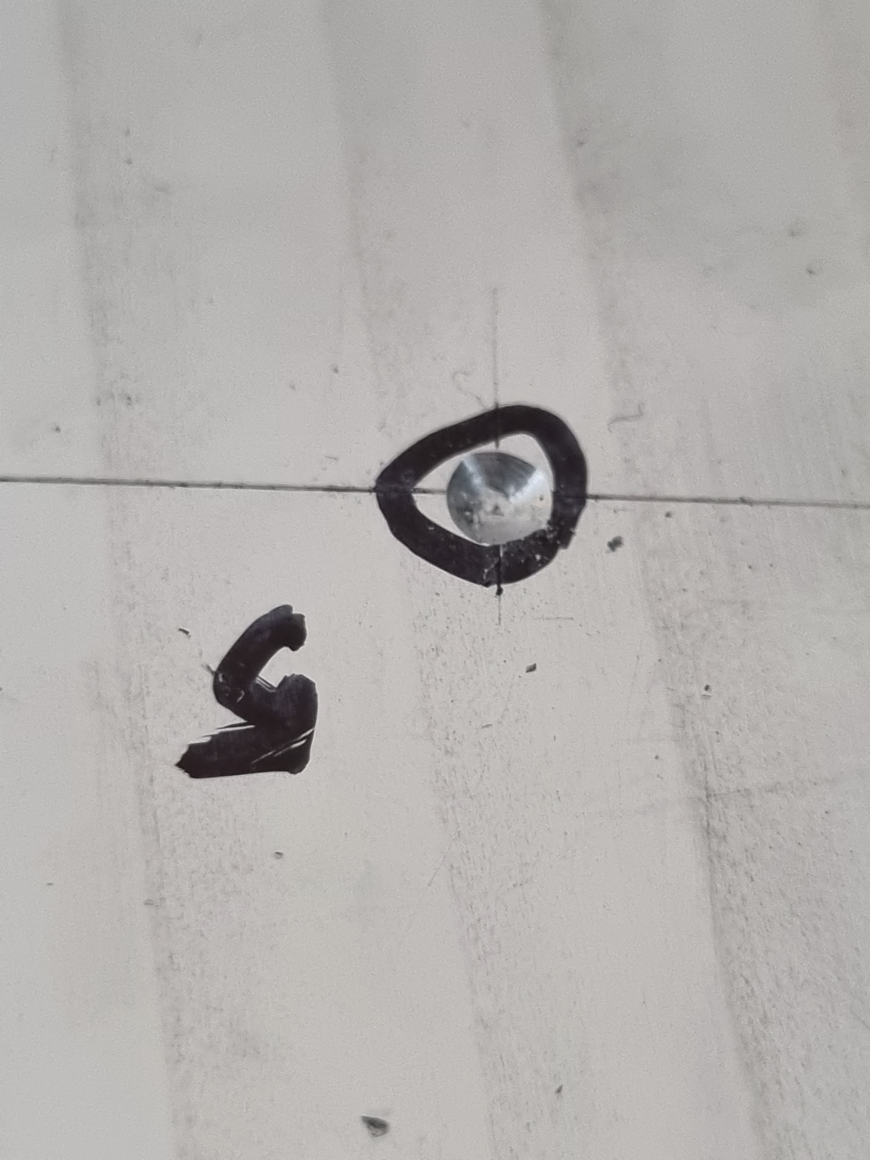
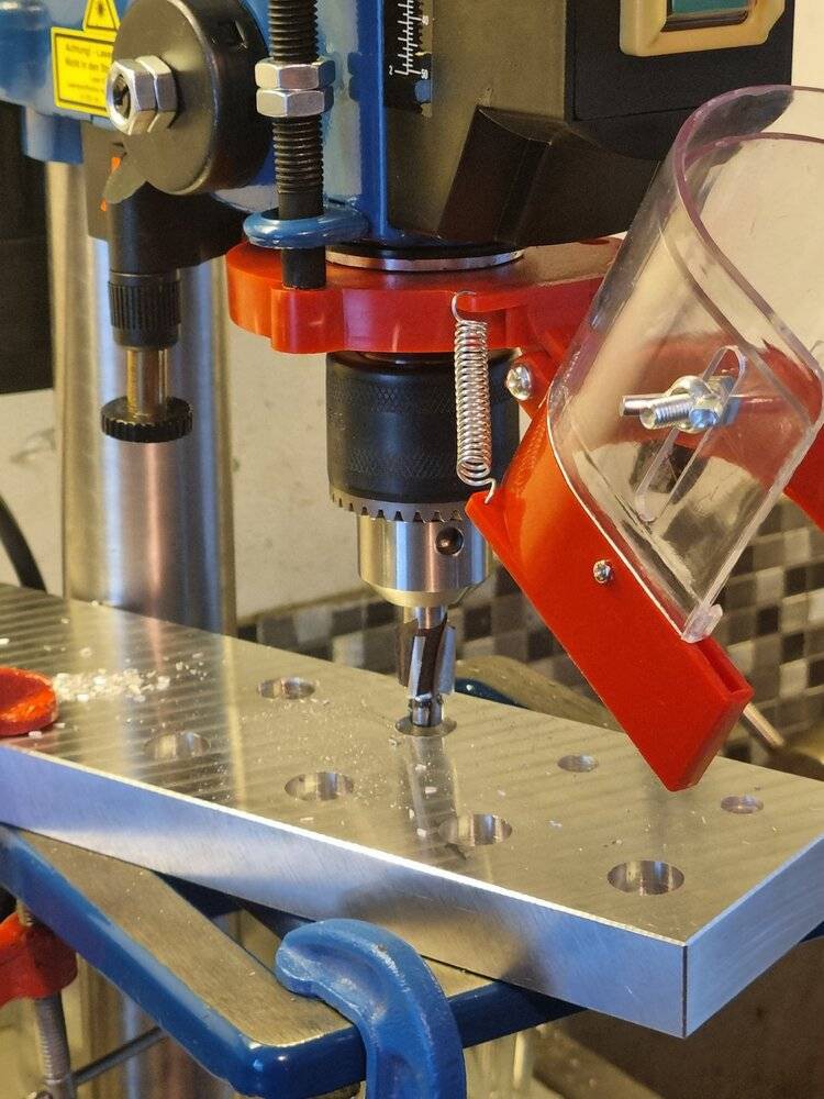
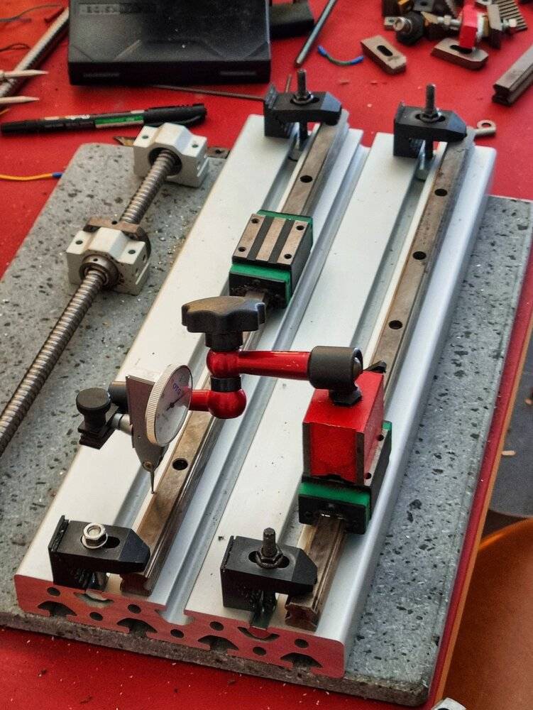
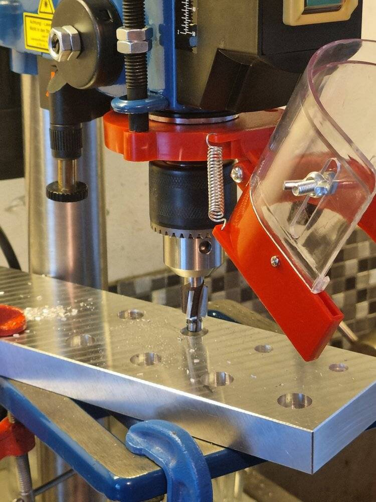
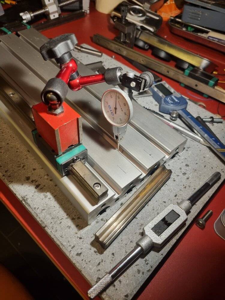
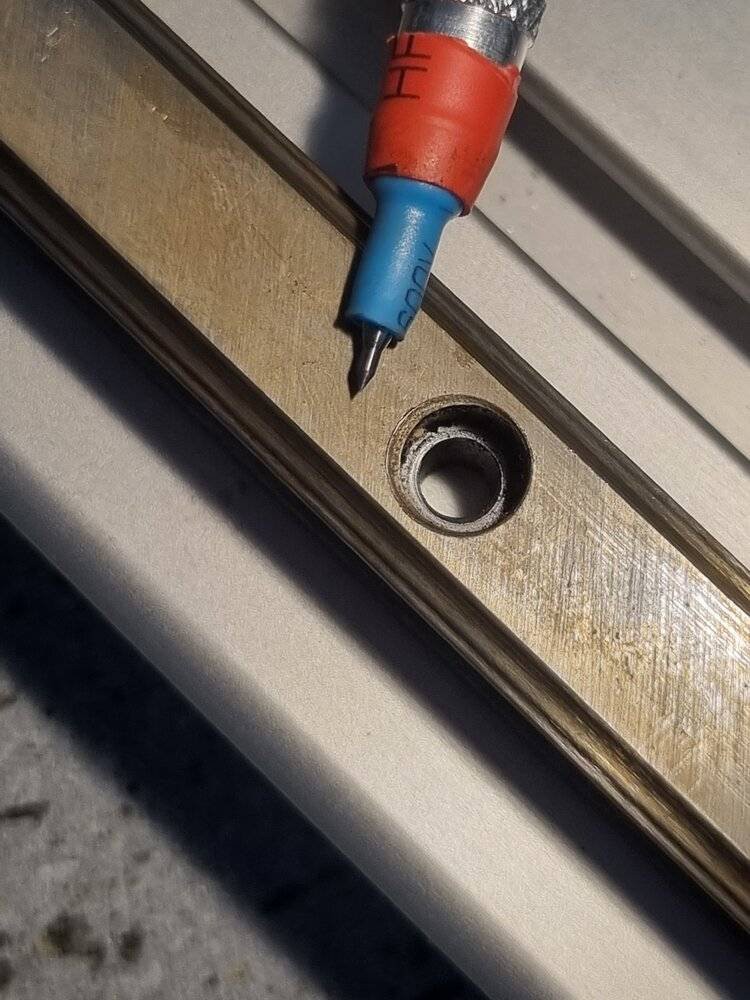
I assembled this milling machine with minimal tooling:
- A drill press.
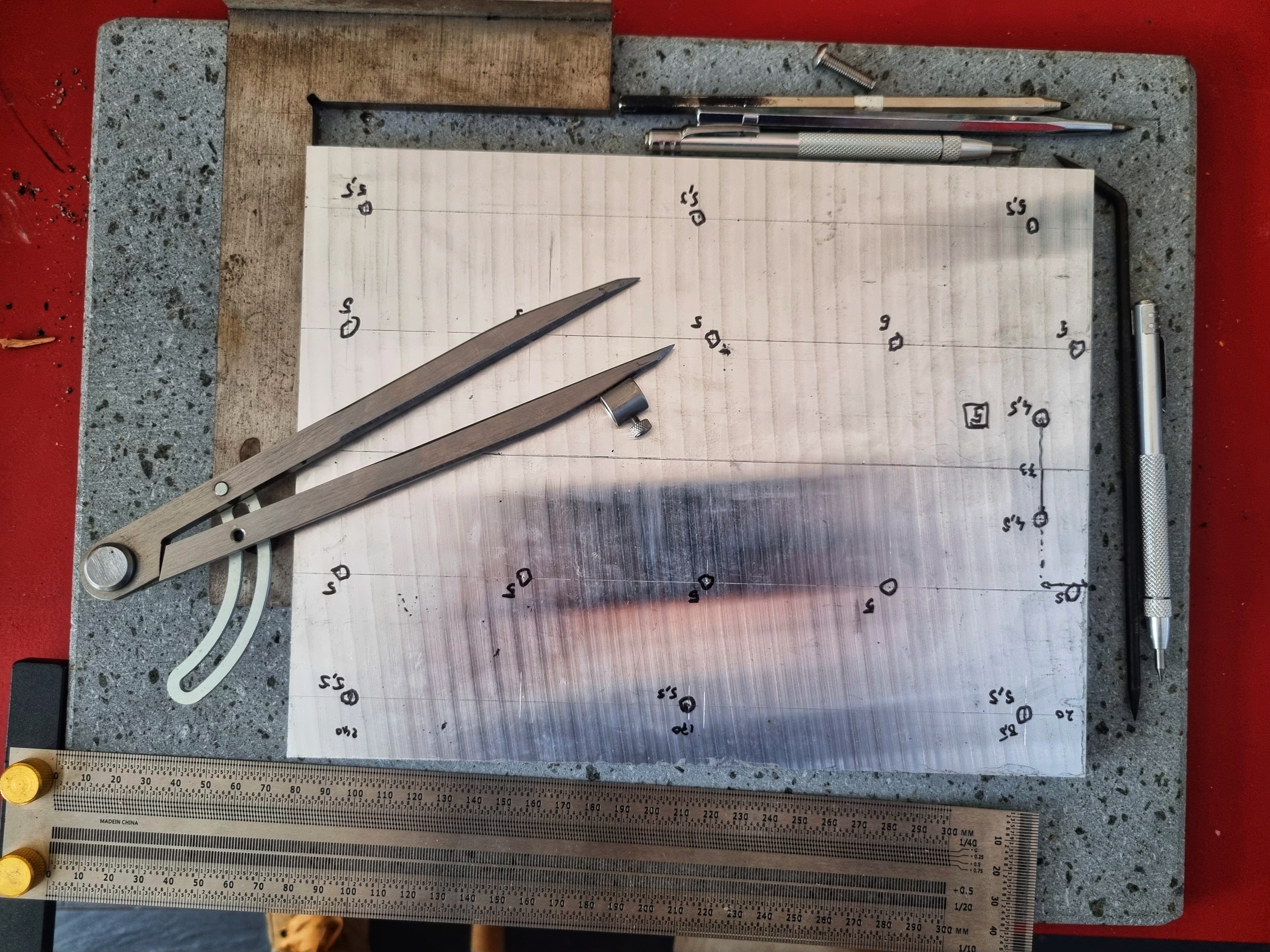
- A ruler, compass, and carbide scribers.
- An angle grinder to size the linear guide rails.
- Pre-cut and dimensioned aluminum profiles and plates.
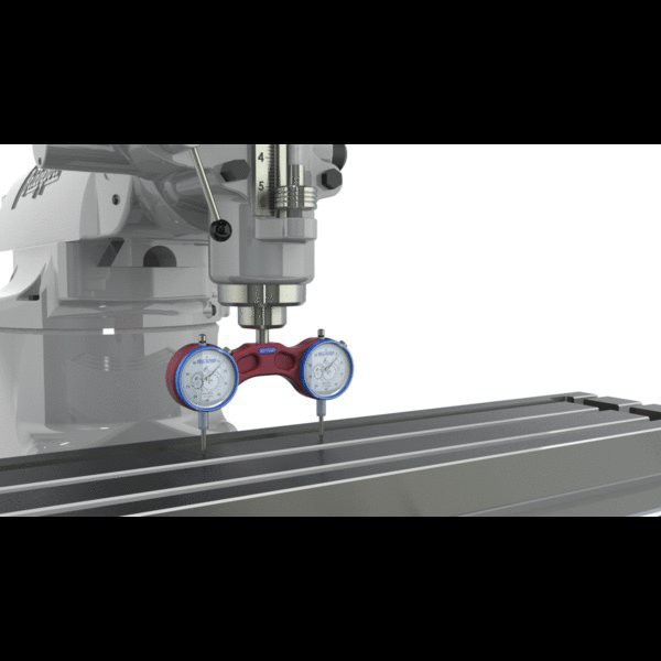
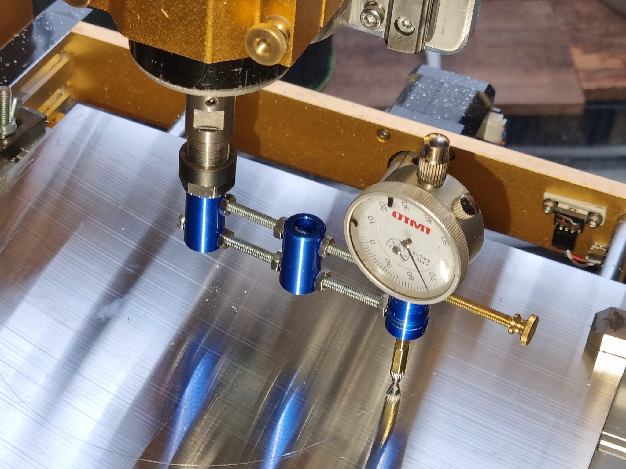
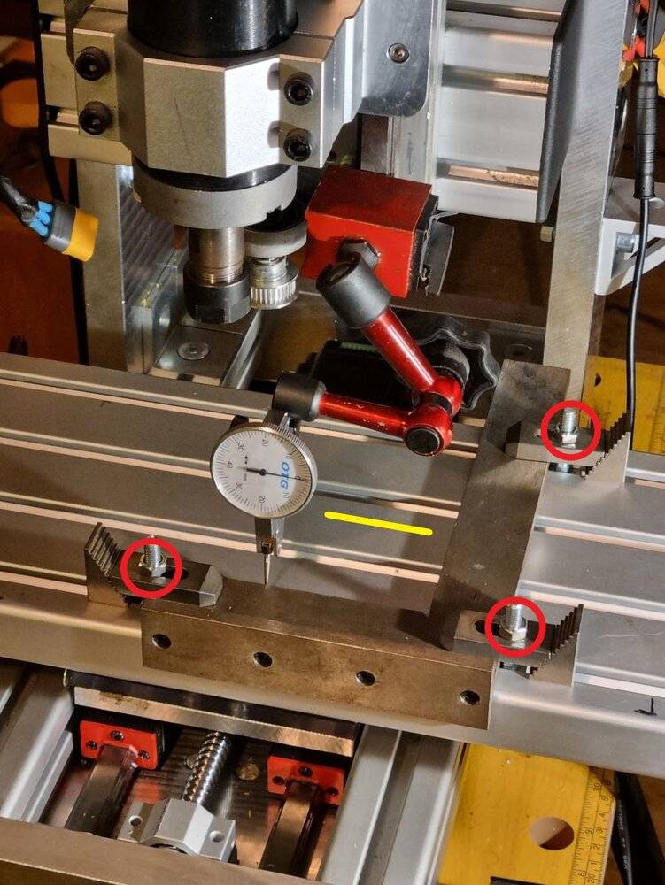
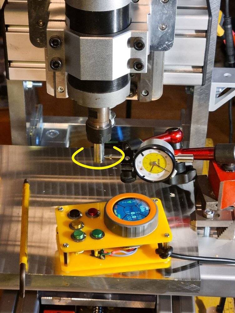
- A dial gauge with a stand for assembly and calibration.
 |  |  |
 |
Compactness and Work Area
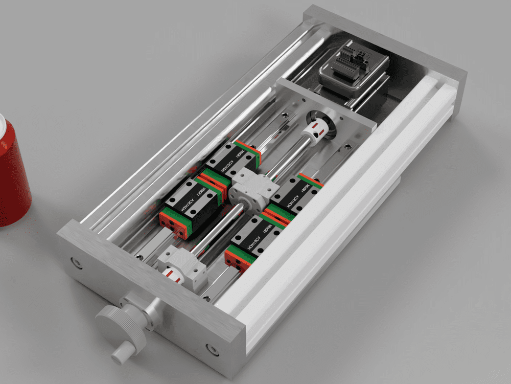
Routers typically offer a larger work area compared to the classic structure. To maximize the working area, I did not use standard bearing blocks for the SFU1204 ball screws:
-
The assembly is reversed compared to the recommended setup: the fixed bearing block is placed opposite the motor, and there is no floating bearing.
-
The fixed bearing journal is reduced from 10mm to 8mm.
-
This means the ball screw is not a standard SFU, but it is still relatively easy to source.
-
Standard SFU screws can be used, but this would require adapting the design and accepting either a larger machine or a reduced travel range.
Specifications
- Footprint: 500x500x500mm
- Work area: 250x150x150mm
- Linear guides: 4x HGR15 on all three axes
- Motors: NEMA 22, 1.8Nm or 1.2Nm closed-loop
- Controller: FluidNC with CNCjs on a Raspberry Pi
- Speed: At least 4000mm/min
- Verified machining capacity: 1mm cuts with a 6mm end mill, achieving 0.01mm precision with the current spindle.
 Rinar
Rinar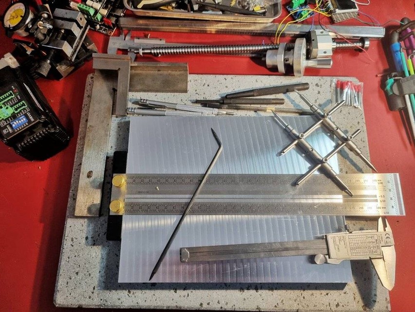




 Adrian Prinz
 3D Meister
 Isaac Zammit
Hello @Rinar , I have been looking for a machine like this for years and I am not happy about anything comercially available. So I am contemplating on building my own and your project looks exactly like what I need. Price is very reasonable and I really like your commitment to quality instead of focusing on low cost. However, while having my toes dipped in various maker areas I am a complete noob in machining and precision construction, but I am very eager to learn! So I have two questions: do you think I can build it (being an engineer and somewhat capable tinkerer, but without mechanical engineering background and experience) and would you please be able to provide some advice as I am going on? I would be more than glad to document my process and I think it might become an interesting resource for other less-skilled hackers. Anyway, hats off! It looks really really really good.