Close
0%
0%

Heavy Desktop Mill

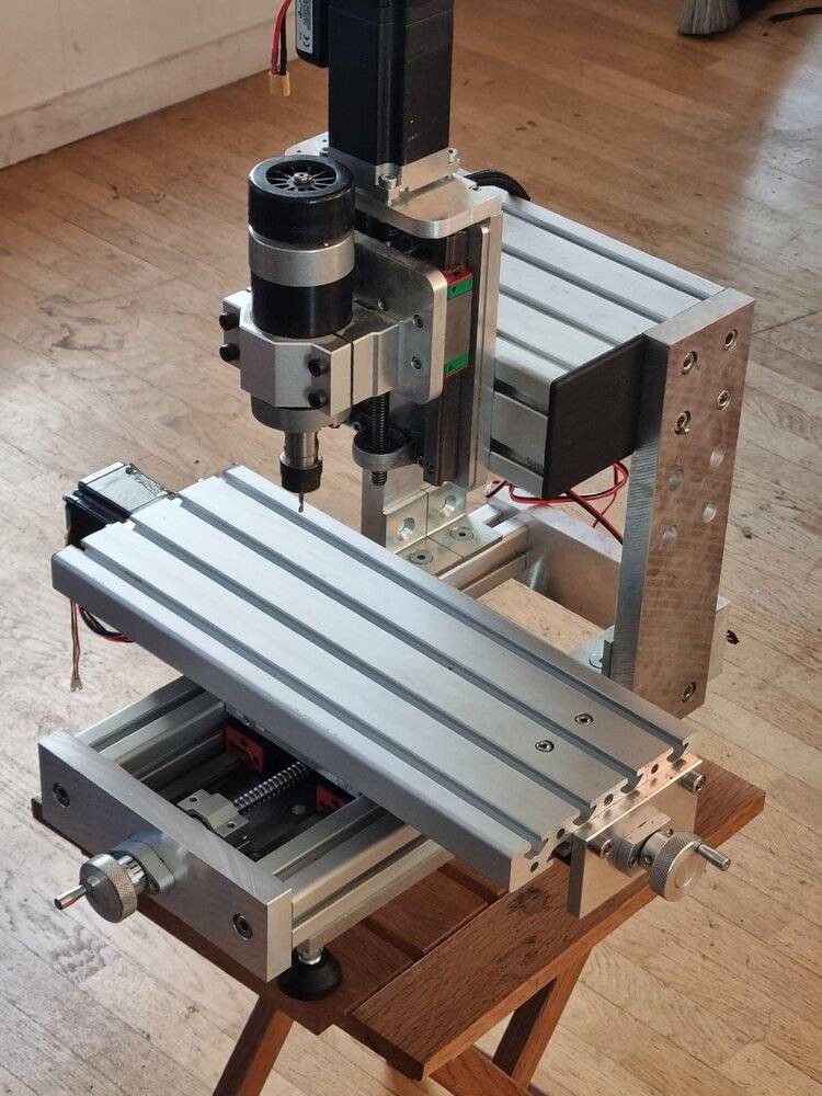
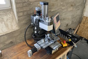
A robust and easy-to-build Cnc tabletop milling machine for precision work and soft metals machining

Similar projects worth following
- Hybrid setup can be used with handwheels or as CNC.
- Optimized axis travel for a reasonably sized working surface 250x150x150
- Over sized structure for soft metals without challenges
- Classic milling machine structure for accurate machining suitable for precision machining (like pcb)
- Limited degrees of liberty for easy tuning
- Functional dimensions rely on known dimensions with low tolerances (such as the thickness of a profile or a linear guide.
- Easy to make with no milling (only drill and cut off aluminium sheet and profile)
- Cute :)

This machine was built with minimal tooling. I will complete the project with photos of the manufacturing process, 3D plans, the adjustment process, and examples of finished parts.

Design and Manufacturing Principles

This machine was designed as a versatile tool capable of performing most small machining tasks typically encountered in a small amateur or professional workshop. It fits well in a compact workshop or laboratory.
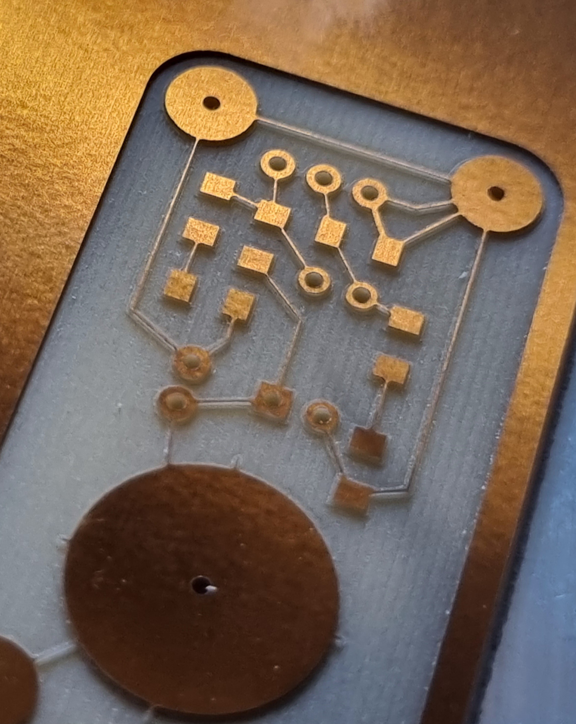
Structure and Kinematics

I opted against a router-style structure because it is less rigid and significantly harder to calibrate. The classic structure of conventional milling machines (XY+Z) offers several advantages compared to a router structure (Y+XZ). First, the X and Y axes are interconnected, making it much easier to adjust their perpendicularity. The X and Y rail planes are naturally parallel. Second, and more importantly, the classic structure has fewer degrees of freedom, meaning fewer adjustments are required.

Additionally, each adjustment affects only one axis at a time. On a router, adjusting the Y-axis can disrupt the Z-axis, making the calibration process more complex and requiring more tools.

During the design phase, I focused on ensuring the machine could be finely and easily adjusted by following these principles:

  • Minimize joints and the number of parts, avoiding components like angle brackets.
  • Avoid thickness adjustments (e.g., no shims); all adjustments are rotational.
  • Contact surfaces influencing kinematics are never machined surfaces, as no cutting process at my disposal guarantees perfect perpendicularity or parallelism.
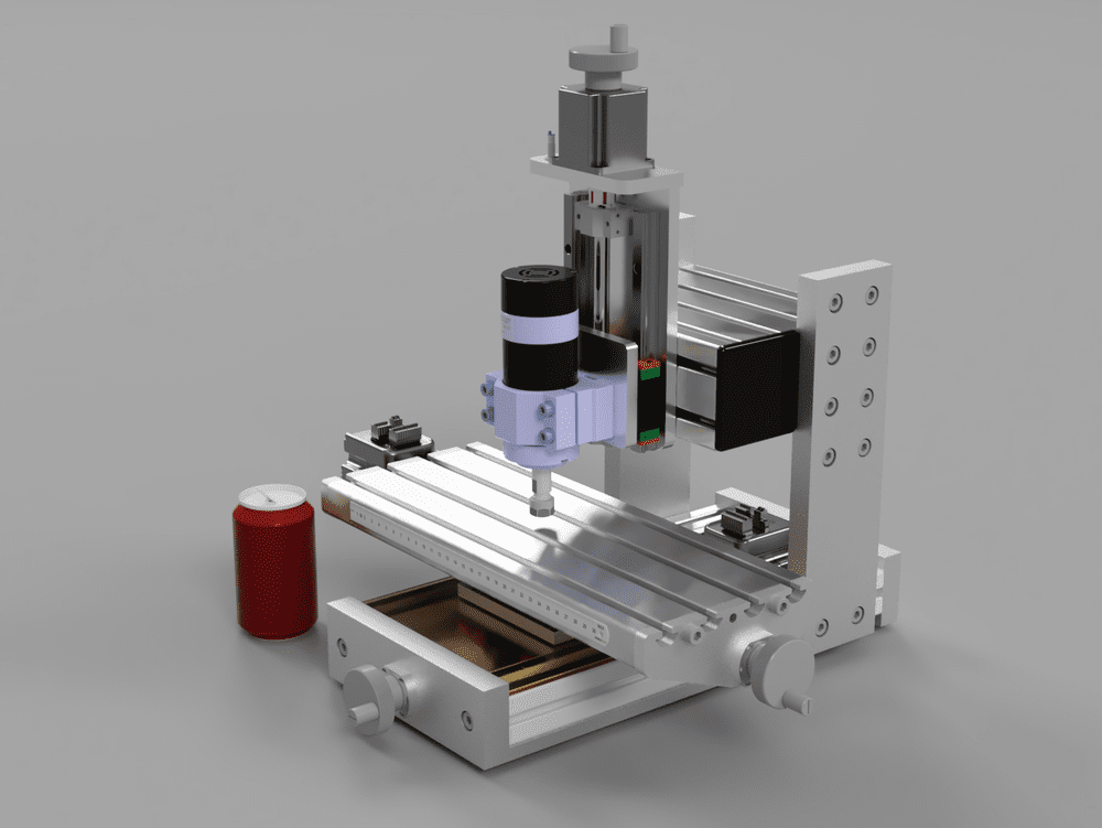
First version

Rigidity

The entire structure is oversized for enhanced rigidity. I used 20mm-thick plates and heavy-duty aluminum profiles designed for structural applications. For instance, the head profile measures 80x160mm and weighs 2kg on its own. The entire structure is assembled using 8mm screws, allowing for secure clamping.

Detailed adjustment instructions will be provided.
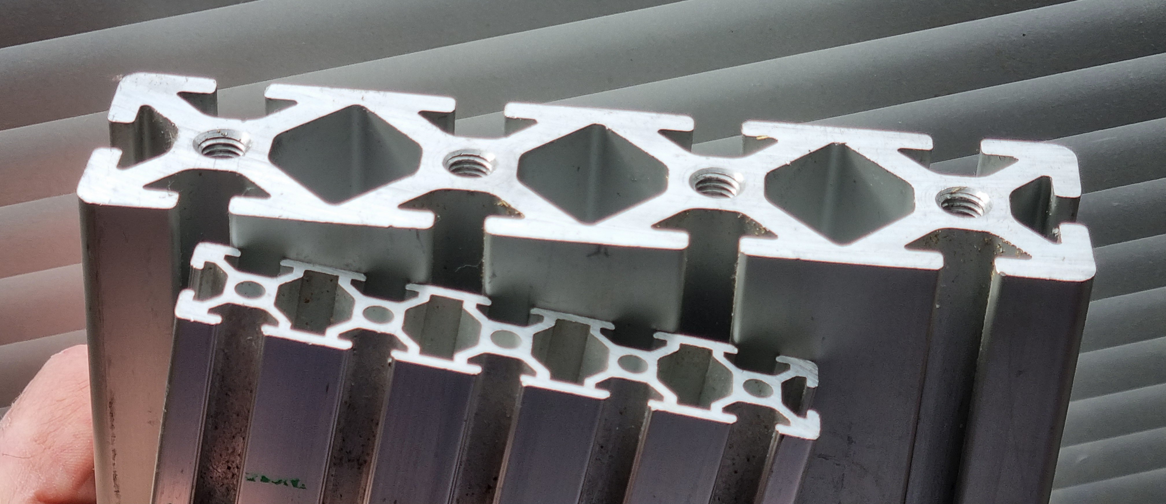
20mm vs 40mm strong profile

Manufacturing

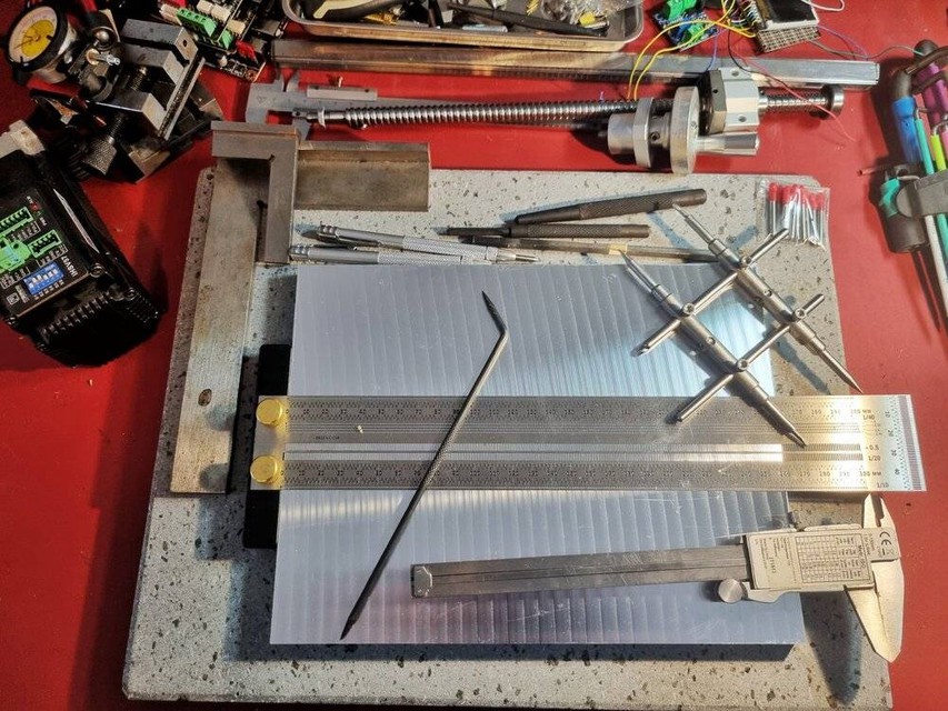
I assembled this milling machine with minimal tooling:

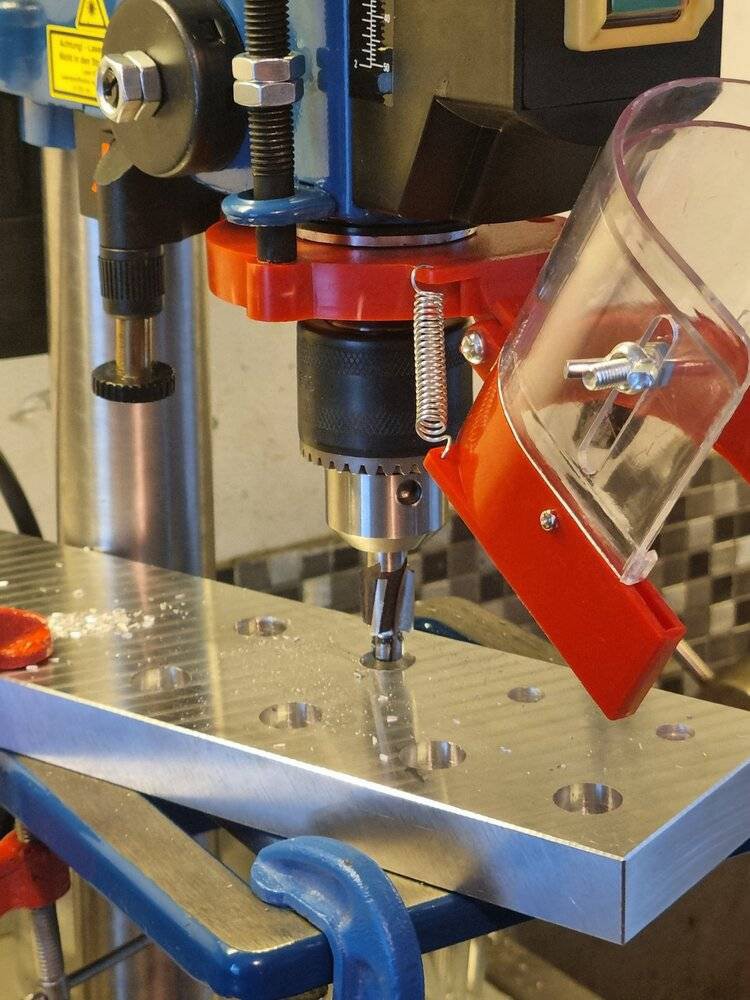
  • A drill press.
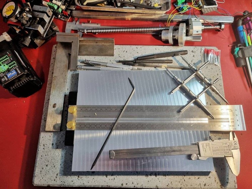
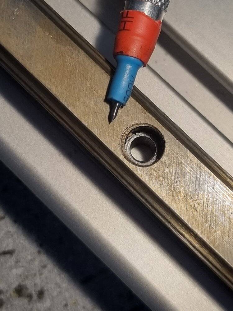
  • A ruler, compass, and carbide scribers.
  • An angle grinder to size the linear guide rails.
  • Pre-cut and dimensioned aluminum profiles and plates.
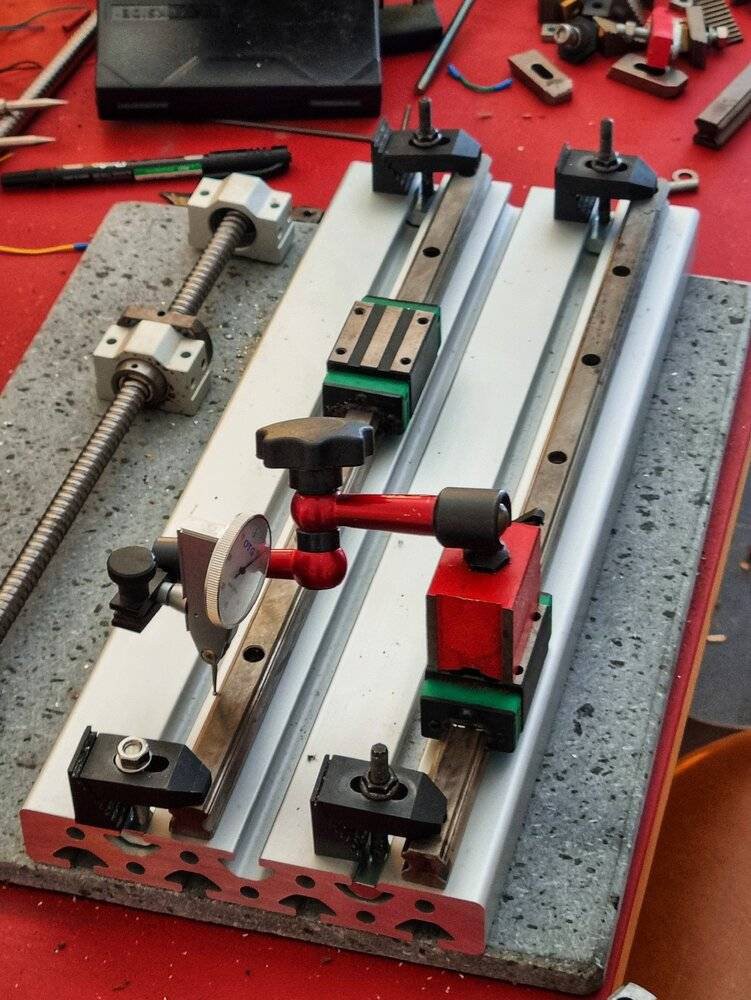
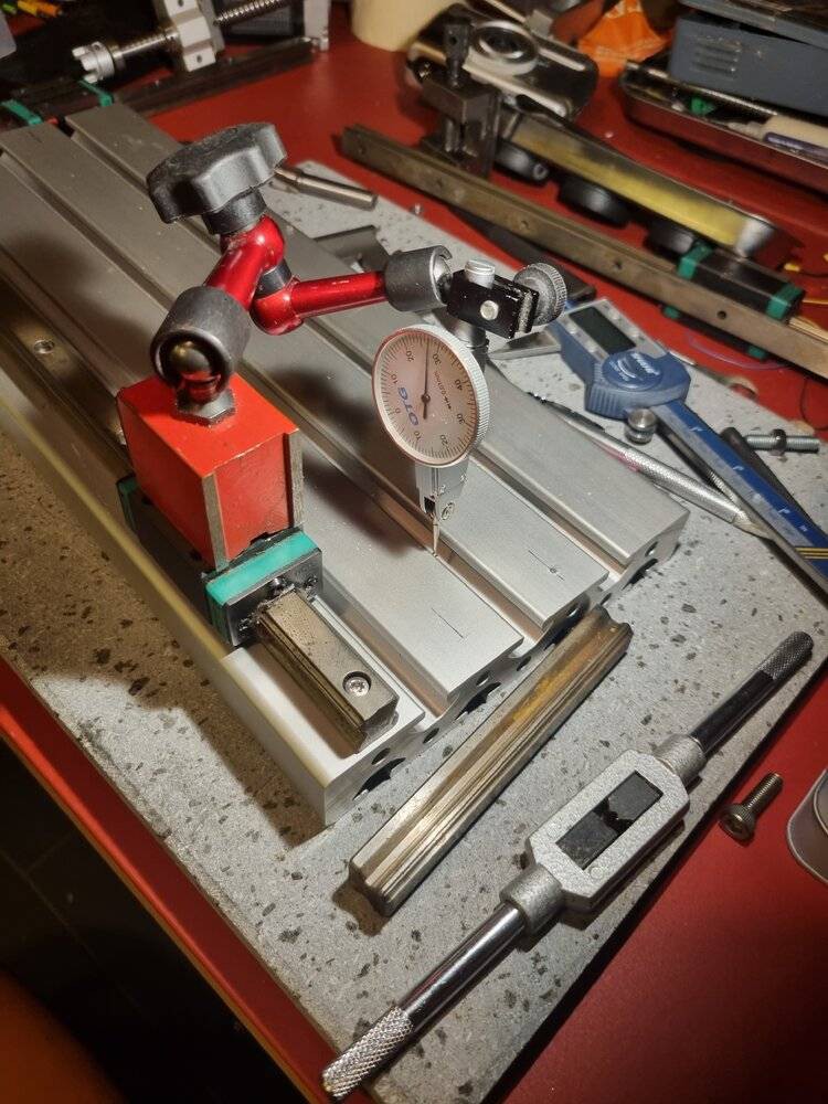
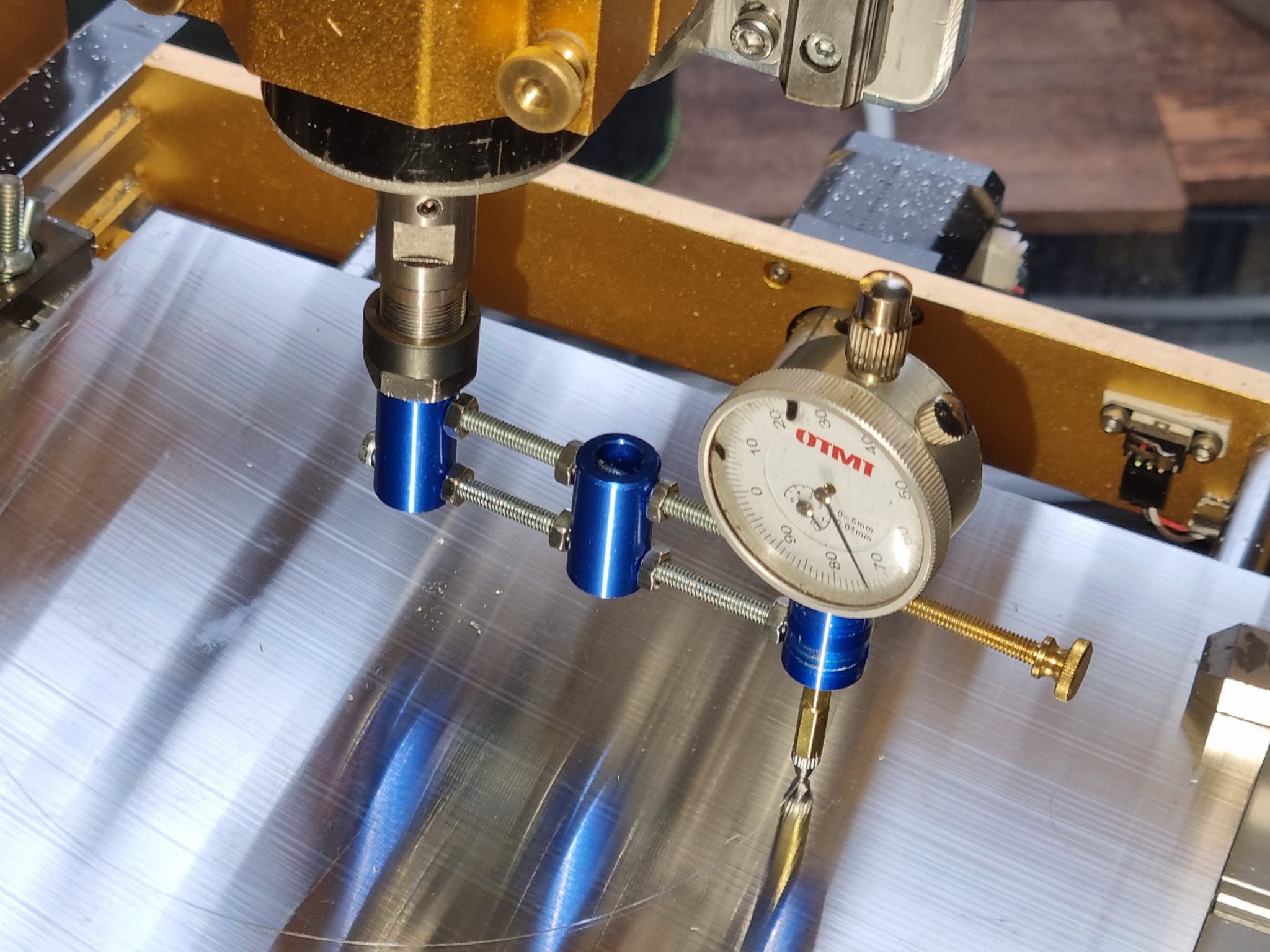
  • A dial gauge with a stand for assembly and calibration.
Compactness and Work Area

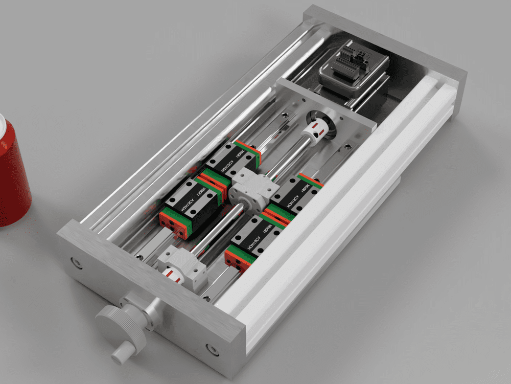
Routers typically offer a larger work area compared to the classic structure. To maximize the working area, I did not use standard bearing blocks for the SFU1204 ball screws:

  • The assembly is reversed compared to the recommended setup: the fixed bearing block is placed opposite the motor, and there is no floating bearing.

  • The fixed bearing journal is reduced from 10mm to 8mm.

  • This means the ball screw is not a standard SFU, but it is still relatively easy to source.

  • Standard SFU screws can be used, but this would require adapting the design and accepting either a larger machine or a reduced travel range.
Specifications

  • Footprint: 500x500x500mm
  • Work area: 250x150x150mm
  • Linear guides: 4x HGR15 on all three axes
  • Motors: NEMA 22, 1.8Nm or 1.2Nm closed-loop
  • Controller: FluidNC with CNCjs on a Raspberry Pi
  • Speed: At least 4000mm/min
  • Verified machining capacity: 1mm cuts with a 6mm end mill, achieving 0.01mm precision with the current spindle.

  • 1
    Manufacturing and building instructions

    Manufacturing Parts

    The entire machine is made of aluminum plates and profiles with drilled holes, with no complex parts requiring machine tools like a milling machine or lathe. All components can be ordered pre-cut to size and drilled with the tools you have available.

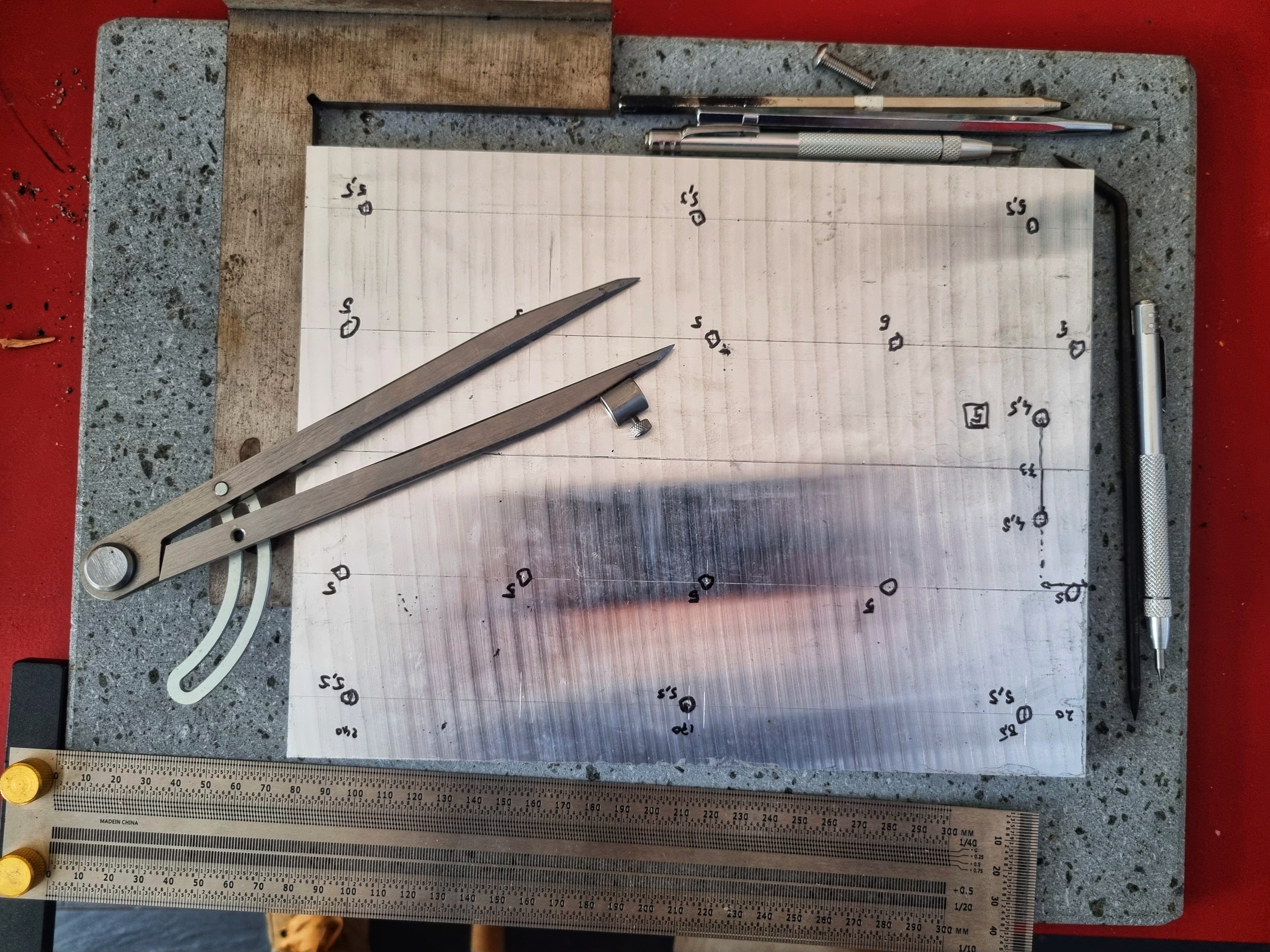
    For positioning the drill holes, I used traditional methods with a compass, a graduated ruler, a square, and carbide scribers. A reference edge and origin point are chosen, and axes are marked out from this point.

    Precision is important but manageable. When drilling, I typically add 0.5mm to the bolt diameter (e.g., M6 = 6.5mm) and aim for at least 0.5mm accuracy when marking.

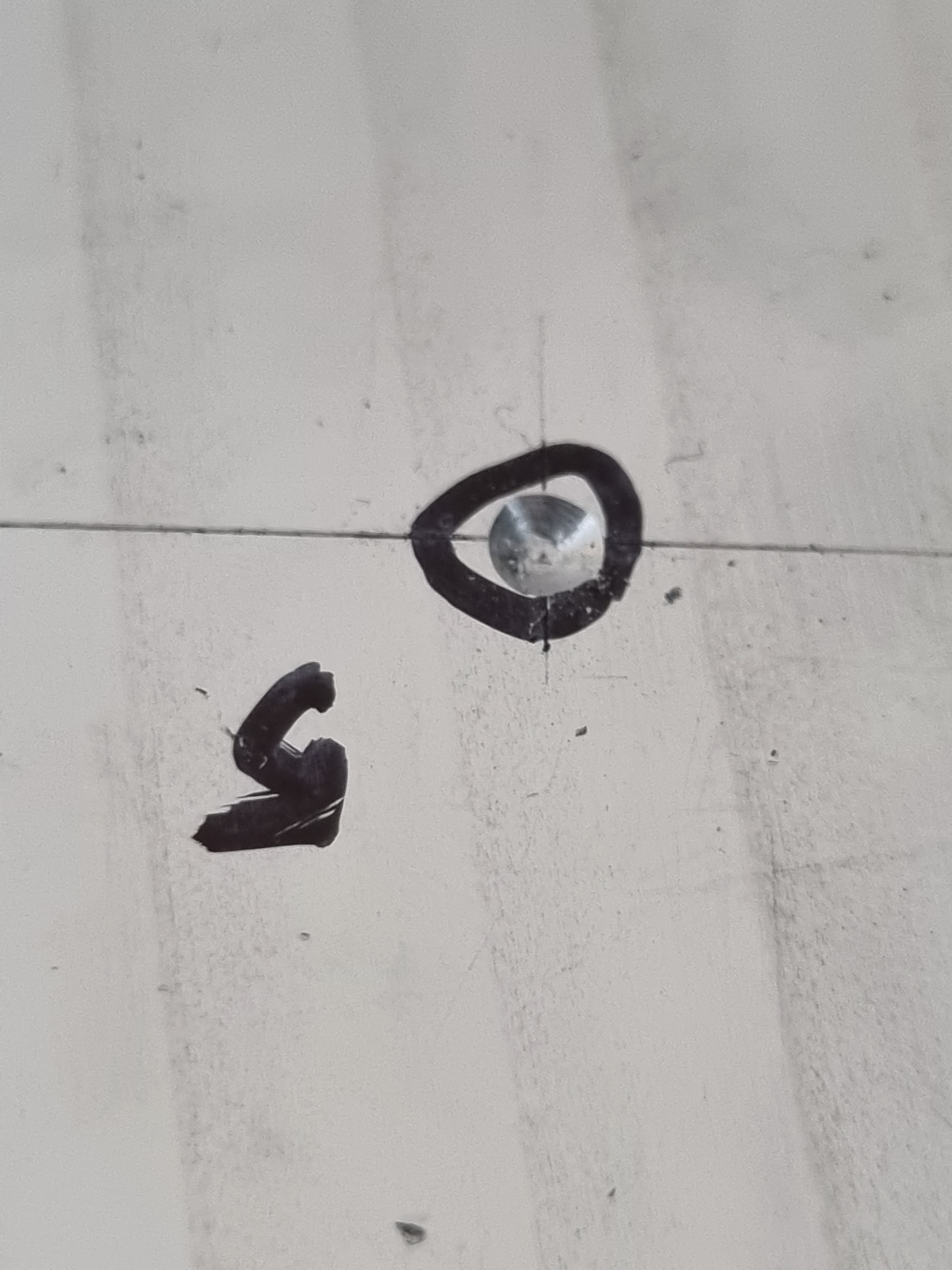
    Once marked, the drill hole locations are center-punched.

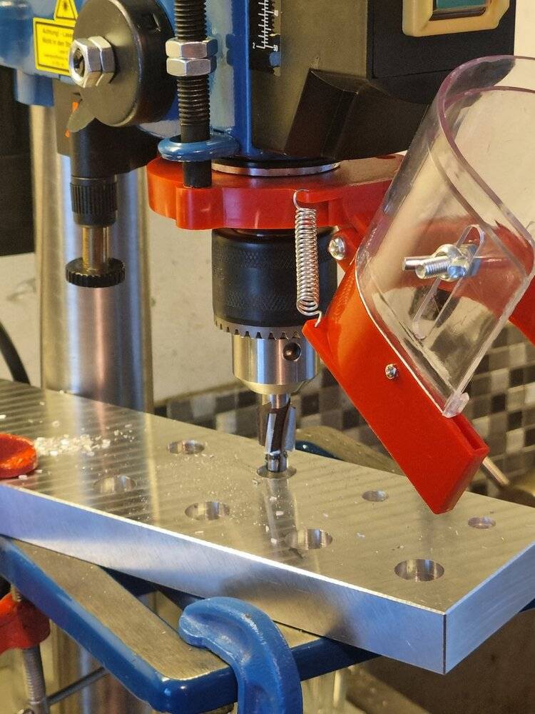
    The countersinking for bolts is done using countersinking tools. For M8 bolt countersinks, a good drill and ideally a drill press are required.

    Assembly and Adjustment

    I drill the screw passages for the rails and bearing blocks at the last stage, using a dial gauge to ensure the rails are perfectly parallel.

    The principle is straightforward: I drill and mount the first rail parallel to one side of the frame, clamp the second rail, and ensure it is parallel to the first using a dial gauge. Once the position is perfect, I center-punch the locations with an adjusted-diameter carbide scribe.

    The rest of the assembly is straightforward. Once the machine is assembled, it needs to be adjusted.

  • 2
    Fine adjustment of geometry

    Fine-tuning is crucial as it determines the precision of machining geometry.

    It also impacts surface finish quality, noise, and the lifespan of cutting tools.

    Adjustment with shims or by rotation

    Connections between two elements typically involve planar contact with screws. There are two types of adjustments: rotation of parts by pivoting them against each other and the use of shims.

    Shims can be a nightmare if you don’t have a set of sheets with different thicknesses. That’s why I favored rotational adjustments during the design phase.

    Degrees of freedom

    I define a degree of freedom as the possibility of rotational adjustment around an axis. The ideal structure minimizes the degrees of freedom and reduces the number of parts.

    It’s also important that adjustments follow the machining XYZ coordinate system. Moreover, it’s far more practical for an adjustment to affect only one axis. If a rotational adjustment affects two axes, the process becomes more complex and time-consuming.

    On this milling machine, there are four degrees of freedom:

    • Perpendicularity of the X and Y axes
    • Perpendicularity of the X and Z axes
    • Perpendicularity of the Y and Z axes
    • Coaxiality of the Z-axis with the spindle axis

    Tooling

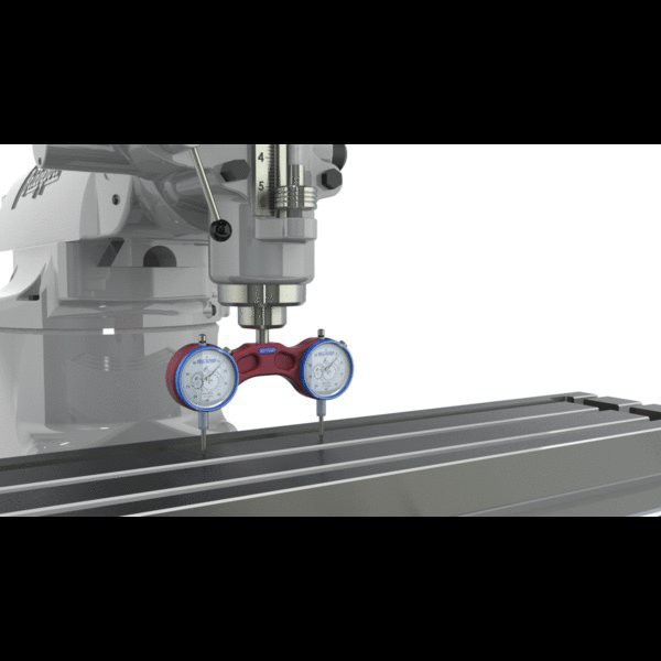
    I use a dial indicator with a magnetic base and a DIY dial indicator holder. You can make your own; it doesn’t require precision.

    Adjustment process

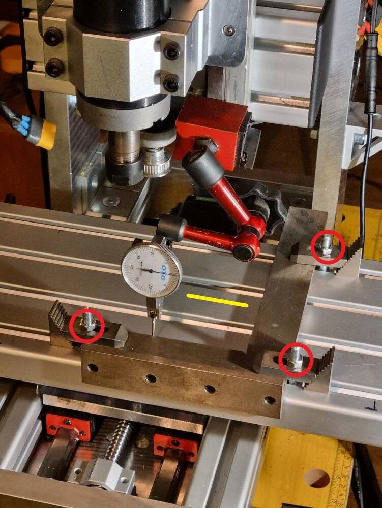
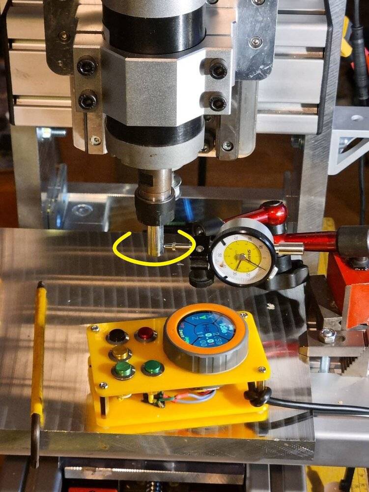
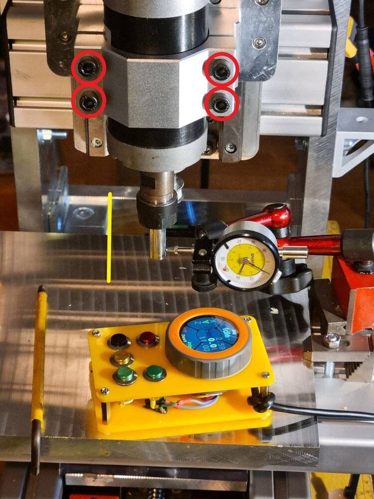
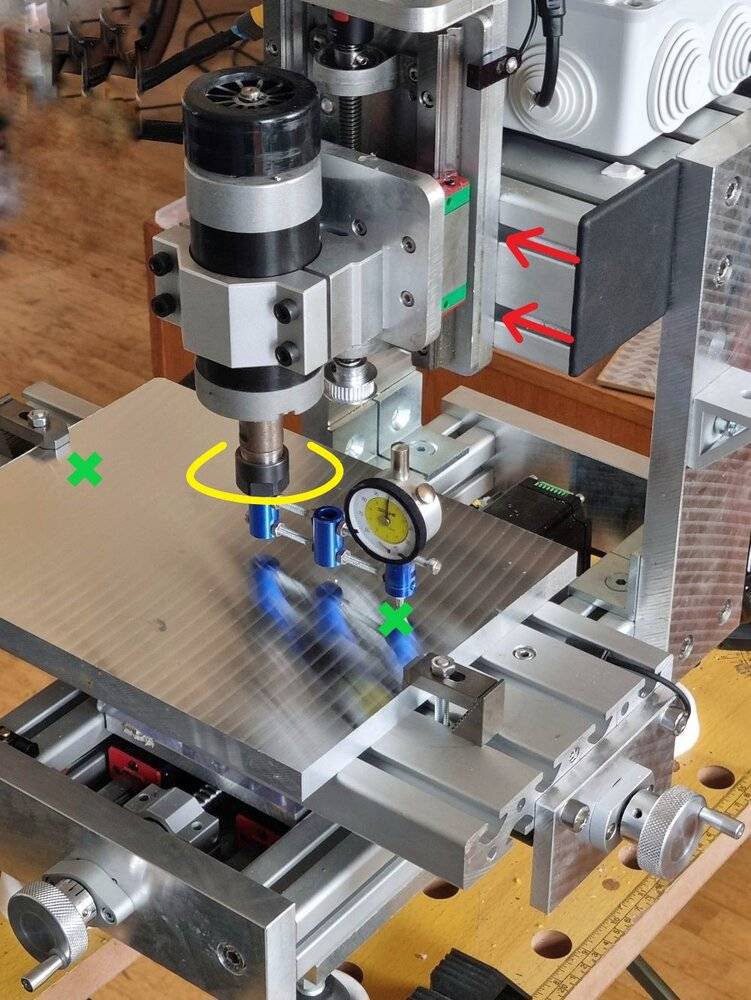
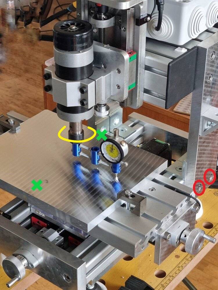
    • Red: screws to tighten/loosen. Always remember to work in rotation; one screw should always be tighter than the others.
    • Yellow: the movement to apply. The movement should be as long as possible with minimal dial indicator displacement. Less than 0.05 over 50–100 mm provides excellent precision.
    • Green: control points.
    1. Place a precision square on the table and adjust its position so one edge is // to the X-axis.

    2. Move the dial indicator along the Y-axis and adjust the Y-axis. => The X-axis is now perpendicular to the Y-axis.

    3. Materialize the spindle’s Z-axis by inserting a pin or drill bit. Check the spindle’s concentricity (it’s not always perfect).

    4. Adjust the // between the spindle axis and the Z-axis rails. => The Z-axis rails are now // to the spindle’s Z-axis.

    5. In the final step, the perpendicularity of the X and Z axes relative to Z is adjusted simultaneously. Mount the dial indicator holder in the spindle. => The machine is now perfectly aligned along all axes.

View all instructions

Enjoy this project?

Share

Discussions

Frantisek Havluj wrote 5 days ago point

Hello @Rinar , I have been looking for a machine like this for years and I am not happy about anything comercially available. So I am contemplating on building my own and your project looks exactly like what I need. Price is very reasonable and I really like your commitment to quality instead of focusing on low cost. However, while having my toes dipped in various maker areas I am a complete noob in machining and precision construction, but I am very eager to learn! So I have two questions: do you think I can build it (being an engineer and somewhat capable tinkerer, but without mechanical engineering background and experience) and would you please be able to provide some advice as I am going on? I would be more than glad to document my process and I think it might become an interesting resource for other less-skilled hackers. Anyway, hats off! It looks really really really good.

  Are you sure? yes | no

dekutree64 wrote 01/13/2025 at 14:26 point

Very nice design and writeup!

What is the total weight of the machine? And approximate cost of components?

From what I can see, it still needs a few more features. Dials on the hand wheels, pause/resume buttons, and individual enable/disable switches for each stepper motor (or can that be done from the LCD?). It is very useful to be able to e.g. pause and switch off Z stepper, pull the tool up out of a hole and clean out chips/apply lubricant, and then put it back down exactly where it was and resume. Or manually operate Z with precision for drilling holes. I only do shallow drilling with CNC due to the unpredictability of chip jamming.

Is the spindle electrically isolated from the bed? I don't know how I could live if mine wasn't, because I use electrical contact for probing, for zeroing Z after each tool change, and with a rod in the spindle for centering on internal or external features. I also have an LED connected to the spindle so it lights up when contact is made for manual operation.

I also recommend protecting the Y rails from chips. My covers are just sheets of typing paper coated with box tape, and stuck to the machine with blue masking tape. Surprisingly effective. It does hang over the Y knob annoyingly when moved forward, but not really a big deal.

  Are you sure? yes | no

Rinar wrote 01/13/2025 at 15:24 point

Hello @dekutree64,

Thank you for your comment. I see you've thoroughly analyzed the machine and pointed out areas for improvement.

I haven’t weighed the machine, but it probably weighs around 35 kg.

The question of cost is a bit tricky for me because, on one hand, I reused parts from another machine, but on the other hand, I ordered most components from a German supplier who does excellent cutting and finishing work but is probably not the cheapest. Using the same profiles as mine, outsourcing the cutting in Europe, and sourcing quality components (steppers, linear guides, etc.), I think the machine would cost between $2000 and $3000. That’s an estimate for European pricing. By being a bit resourceful, I think the cost could be reduced to around $1500.

The control system isn’t finalized. I’m currently using a FluidNC controller and a Raspberry Pi running CNCjs. For the interface, I have a FluidDial (https://github.com/bdring/FluidDial) visible in some photos and a numeric keypad inspired by this project (https://github.com/mariolukas/cncjs-pendant-numpad). The Raspberry Pi touchscreen and the keypad let me handle the essentials: disabling motors, controlling the spindle, overrides, etc.

But I plan to redo everything. My goal, since I have closed-loop stepper motors that know their absolute positions, is to update the controller's work coordinates when I reactivate the motors. Not a big deal, and the machine will be realy hybrid. I’ll update the project when I have something to show.

No, my spindle isn’t isolated. I went with an isolated probe setup using optocouplers, an LED, and a buzzer  (which is also very convenient). For PCBs, I use a acrylic glass spoilboard. But you’re right, having an isolated spindle is a good idea. I’ll definitely consider doing that.

And yes, chips are a problem. Like you, I’m using paper for now. I made a vinyl bellows fixed with magnets, but it’s not great. The design allows for a acrylic glass sheet between the X and Y axes using pillars rather than a plate. It’s still an option, but I didn’t want to complicate things too much.

Thank you for your message, it gives me the motivation to continue and develop the project further.

  Are you sure? yes | no

dekutree64 wrote 01/13/2025 at 18:41 point

Oh yeah, with closed loop you don't need physical dials. And that would be convenient having it hold its exact position when reactivated, so you can use the steppers as axis locks when manual machining. Mine jumps a small amount when the steppers are reactivated, depending on where it is in the stepping cycle.

I tried making a bellows/accordion cover on my lathe out of paper and box tape, but it's too stiff and doesn't work very well, plus is a pain to get chips out of the folds. I recommend keeping them flat on the mill, so they can be vacuumed clean in a few seconds. But no can do on the lathe where it would either be too short to cover enough of the rails, or run into the headstock when working near the chuck. I might try one of those telescoping sheet metal types next.

  Are you sure? yes | no

Similar Projects

Does this project spark your interest?

Become a member to follow this project and never miss any updates