Following Dylan's lead, here's the recipe:
Preparation time: 5 minutes, plus printer time (an hour each in my case)
Ingredients:
1x Threaded rod: Material, size, pitch and length to taste.
1x Nut for threaded rod
1x Cup magnet with mounting hole, size to taste
1x 3D printed base
1x 3D printed nut holder
Step 1: Print the base part
Step 2: Print the nut holder part
Step 3: Insert the threaded rod into the base
Step 4: Screw the magnet onto the base
Step 5: Insert the nut into the nut holder
Step 6: Spin the nut+holder onto the threaded rod
Done!
I got the cup magnets off Amazon (arrived in 12 hours): cat number B09ZX7SXMF "MAGXCENE Strong Magnets with Holes" in 16 mm size.
The printed parts are modeled in Fusion 360, and printed in PLA. I used a 0.3 mm nozzle and 0.1 mm layers. It's helpful to chase the threads with a tap (1/4-20 in my case), and ream the hole for the magnet screw to size with a twist drill (2mm or 3/32 work for the mystery screws I got with the magnets).
They work splendidly, though they do grab the plate a lot more aggressively than the ceramic magnets I used in the previous iteration, and I'll have to get used to that.

 Timo Birnschein
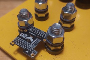
 Dylan Radcliffe
 Miroslav Zuzelka
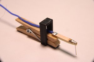
 Henry York
Your suggestions are all great but I didn't read your reply in time, so I went the most convoluted way of designing a M6 nut with a larger hex head and printing that instead... yes, I can be that dumb! :)
Anyway, I think it turned out great!
Here's a picture of the clamp holding a 5x7 stripboard: https://i.imgur.com/GsMY5dS.jpeg
It should work ok with bigger boards too, now I just need some magnets.
Thanks for posting the project!