jenna
jenna-
AI remote wireless monitoring system based on reCamera and Wifi Halow
11/26/2025 at 11:50 • 0 commentsWhy We Need a Remote AI Wireless Monitoring System?
Outdoor environments often lack network coverage, traditional Wi-Fi has very limited range, 4G/5G signals can be unstable, and conventional cameras rely on cloud connectivity, making real-time detection impossible.
- In a forest campsite, you may want to monitor wildlife such as bears; at home or in a warehouse, you may need to detect approaching vehicles or strangers.
- Truck drivers may need to detect suspicious activity near the vehicle when operating in areas with no network coverage.
The core requirements are clear: long-range communication, on-device AI inference, no network dependency, real-time video, and real-time detection outputs.
Technical Highlights of reCamera & Wi-Fi HaLow
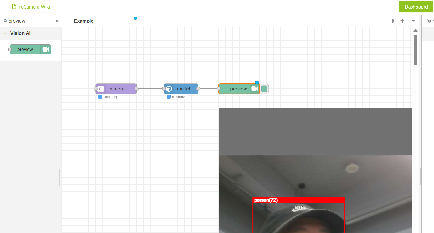
reCamera integrates a 1-TOPS on-device AI accelerator, eliminating the need for external edge-computing hardware. With Node-RED graphical programming, you can push RTSP video streams and output WebSocket detection results simply by dragging a few nodes. The system is highly integrated and works out of the box.
![]()
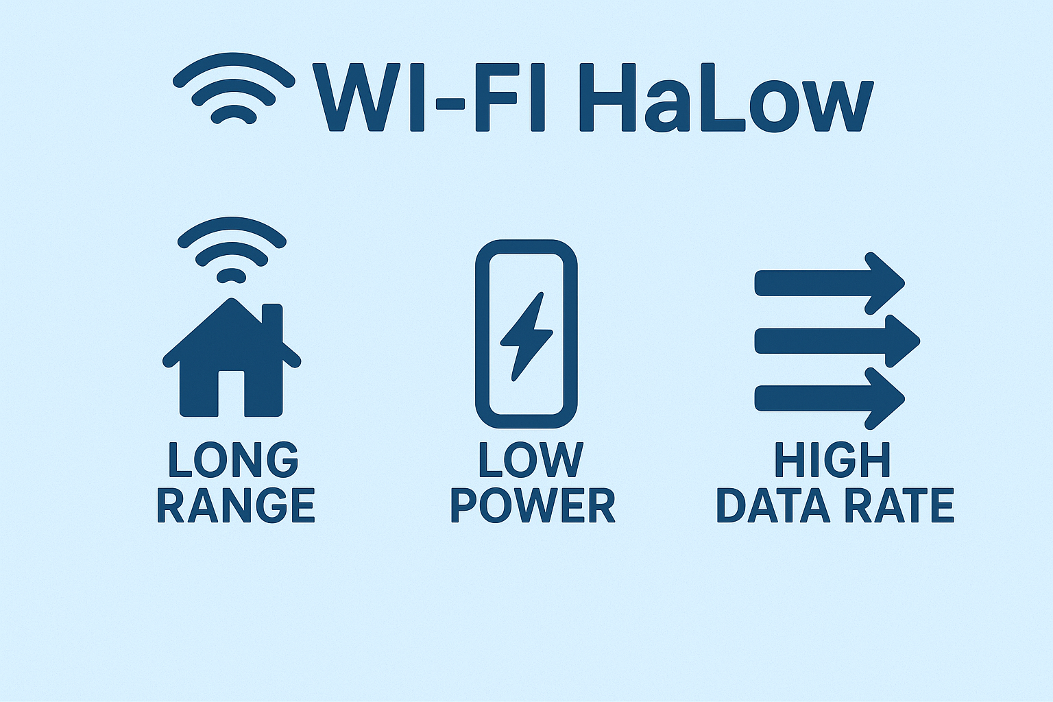
Wi-Fi HaLow is a sub-GHz long-range Wi-Fi standard (802.11ah) designed for low-power IoT devices. Operating in the 902–928 MHz band, Wi-Fi HaLow provides strong penetration, up to 1 km coverage, and bandwidth up to 16 Mbps. It offers significantly higher throughput than LoRa for video transmission while maintaining more stable long-range connectivity compared with conventional Wi-Fi.
System Architecture
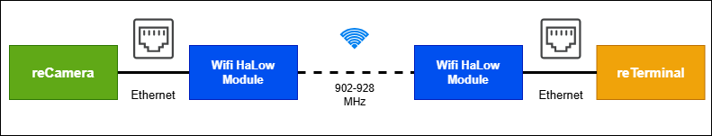
The system is built around a simple concept: reCamera connects to a Wi-Fi HaLow module via Ethernet, the terminal device (such as reTerminal or a laptop) connects to the second HaLow module, and both sides communicate wirelessly over a long-distance HaLow link. The reCamera pushes an RTSP video stream and sends AI detection results via WebSocket, while the terminal receives and displays both in real time.
![]()
What You Need for This Project
- reCamera (any model) - provides on-device AI inference.
- Two Wi-Fi HaLow Transmission Modules/Gateways - create the long-range sub-GHz wireless link.
- Terminal device – reTerminal, Raspberry Pi, laptop, or any edge device with Ethernet + display.
- USB-C cables (×3) – one for reCamera power, two for powering the HaLow modules.
- Ethernet cable – connects reCamera ↔ HaLow / terminal ↔ HaLow.
- 5V 3A USB-C Power Adapter – powers the reTerminal if not using the expansion board
How to Build the System (Simplified Steps)
For details instructions, please refer to: https://wiki.seeedstudio.com/ai_remote_wireless_monitor_system_with_wifi_haLow/#overall-architecture
Step 1 : Log into reCamera, set the camera node (e.g., 480p/5fps), add a Stream node for RTSP output, add a WebSocket node for AI results, and assign a static IP (e.g., 192.168.10.100).
![]()
Step 2: Set one module to AP mode and the other to STA mode, then press the pairing buttons to establish a long-range wireless “virtual Ethernet cable.” The image below demostrates the STA/AP mode selection button and pairing button:
![]()
Step 3: Disable NetworkManager (if using Linux), set a static IP for the terminal (e.g., 192.168.10.3), reboot, and prepare tools like ffplay or VLC to receive the RTSP stream. The final result is illustrated below:
![]()
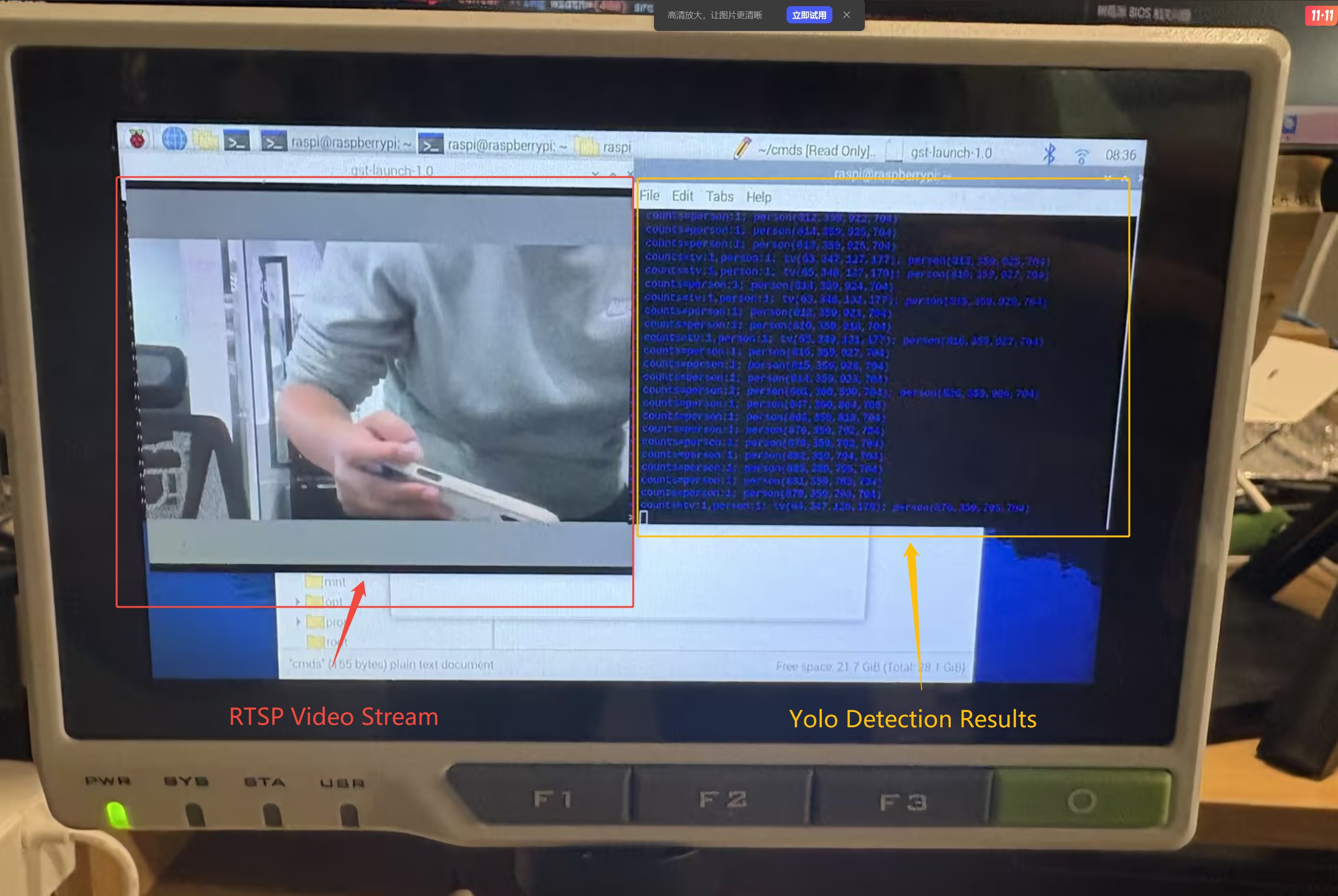
Step 4: Use ffplay (or VLC) to open the RTSP stream, and run wscat -l 9000 to receive real-time WebSocket AI detection results in the terminal.
(Insert image here: final effect — RTSP video + WebSocket text)
![]()
What You Can Build With This System
- Wildlife & Bear Warning System: Deploy a bear-detection model in a forest campsite and monitor the area from hundreds of meters away. Even without network coverage, you can receive real-time alerts and avoid dangerous wildlife encounters.
- Perimeter Security for Homes or Warehouses: Monitor vehicles, strangers, or suspicious activity around a property where wiring or routers are difficult to install.
- Truck and Vehicle Safety Monitoring: Set up a reCamera on a truck to detect people approaching the vehicle, even in remote regions without cellular coverage.
- Agricultural or Farm Monitoring: Use HAloW’s long-range capability to monitor animal intrusion (boars, monkeys, stray dogs) across large fields.
Closing Thoughts
This project demonstrates how reCamera’s on-device AI and Wi-Fi HaLow’s long-range connectivity can create a powerful, fully offline monitoring system. With only a few nodes in Node-RED and simple hardware setup, anyone can build a robust real-time AI vision system that works far beyond the limits of traditional Wi-Fi.
-
Interface/Base Board - SensorCam P4 Housing Assembly
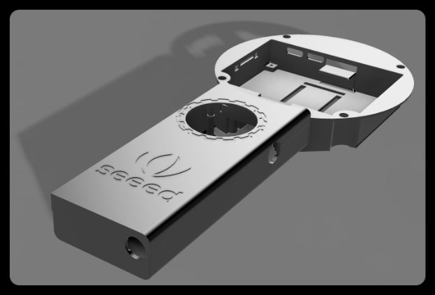
10/16/2025 at 02:19 • 0 commentsAfter several days of waiting, both the PCB board and the 3D model have been printed. All the components are shown in the figure below. We have pre-soldered the PCB and connected the components to the adapter board. Now let's assemble them.
First, fix the main body of the head to the main board with screws.
Then place them in the groove of the handle front cover.
Insert the adapter board into the motherboard, first place the 5-key button, then the knob, and finally the battery.
Then cover the head cover. It is necessary to install the magnet in the magnet slot first, then insert the protrusion of the cover into the empty position of the main board adapter plate, and press it gently.
Finally, cover the handle back cover.
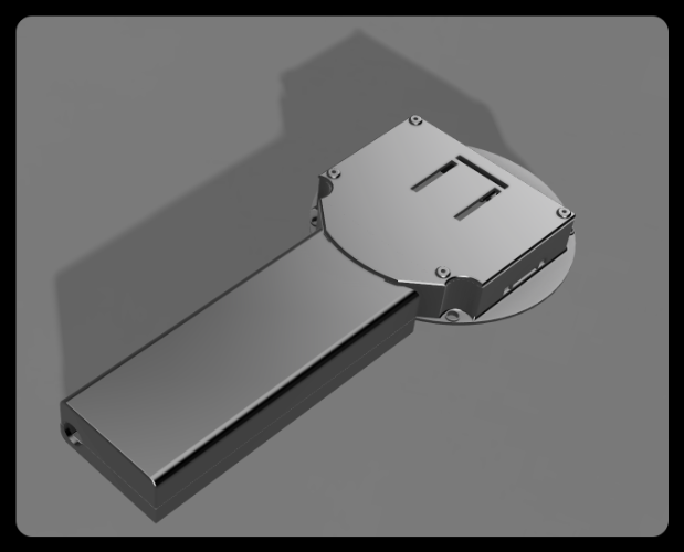
Completed.
Assembly video:
Overall, after all the components are installed into the shell, they are relatively stable, which indicates that our shell design is acceptable. Next, we will try to make the first demo: Camera + ranging module.
-
Interface/Base Board-SensorCam P4 Adapter Board Design
10/11/2025 at 06:31 • 0 commentsAfter selecting the hardware for the SensorCam P4 last week, we found that the interface led out from the main board is located at the bottom right corner of the board. However, what we need to create is a plug-and-play structure. If it is directly plugged in at the original position, the sensor module will not be at the center of the screen, and the obtained data will also be inaccurate. Therefore, we decided to make an adapter board to arrange the pins at the center of the screen, so that more accurate data can be obtained. The schematic diagram is as follows:
Among them, U1 is a 40-pin header used to connect the interface led out from the main board. U2, U3, and U4 are pins led out in the middle of the screen, and a three-sided design is adopted to enhance the stability when the module is plugged in. U5 is the interface for the button, and U6 is the interface for the knob. Among them, pins 4, 5, and 32 will be used as module fixing pins, but they are not entirely fixed pins. The levels of these three pins are different for each module, so these three pins can be used to distinguish different modules. The main controller automatically identifies the module by reading the levels of these three pins, thereby displaying different UIs and data. Theoretically, SensorCam P4 can automatically identify up to 8 modules, but other pins can also be added for expansion. Below is the 3D model of the adapter board:
In addition to the adapter board, we have also made adapter boards for the ranging module and the thermal imaging module to adapt to the main adapter board, so as to achieve a foolproof direct plug design. Below are the schematic diagram and 3D diagram of the adapter board for the ranging module:
Among them, H5, H6, and H7 are ranging modules with an identification code of 000, and their pins are all fixed, so there is no need to worry about inserting the pins incorrectly. The adapter board of the thermal imaging module may be more complicated because it is a board-to-board connector, as shown in the figure below:
We have led out the necessary IIC interface and SPI interface for it. The other unused pins are temporarily led out and can be chosen not to be used. A filter capacitor has also been added to the power supply. Below is its 3D diagram:
H14, H15, and H16 are connected to VCC, GND, and GND respectively, so the coding of the thermal imaging module is 100. Later, we will model the overall shell based on the actual size of these adapter boards connected to the main board.
-
SensorCam P4 Housing Design
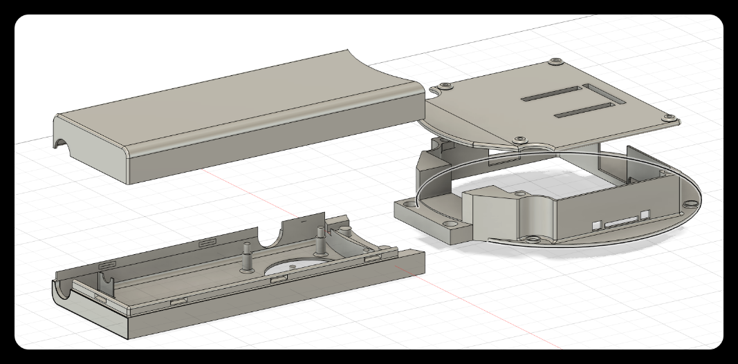
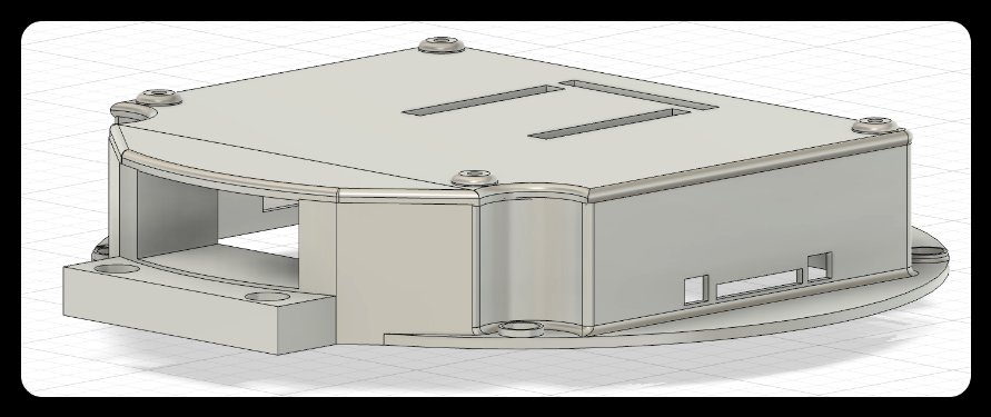
09/18/2025 at 02:17 • 0 commentsThe SensorCam P4 is a handheld device similar in shape to a magnifying glass. To ensure convenience during 3D printing, we divided the device into the handle and the head. The overall design is shown in the figure below:
![]()
- The handle and the head are connected through a mortise and tenon joint,
- the front cover and the back cover of the handle are combined by means of a buckle,
- and the back cover of the head and the main body are combined by magnetic attraction.
The combined state is shown in the figure below:
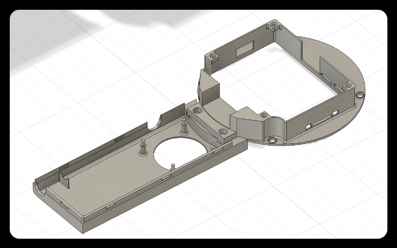
1. Diagram of the connection between the handle and the head
![]()
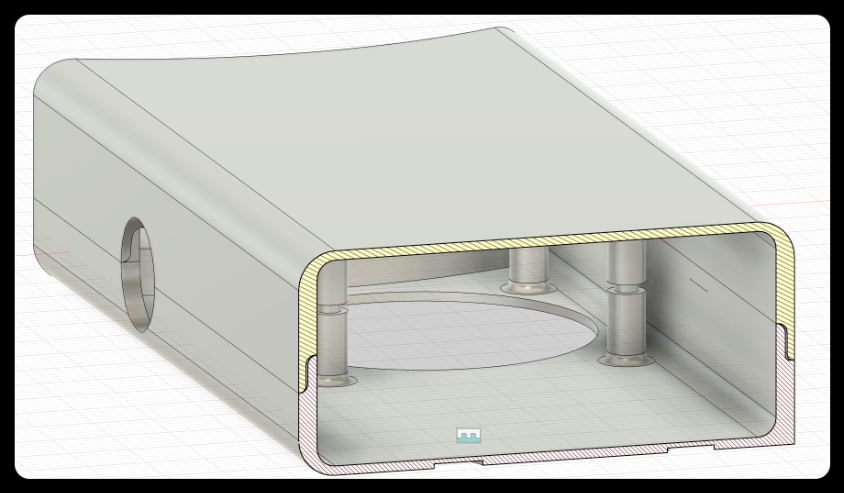
2. Connection Diagram of Handle Front and Rear Covers (Cross Section)
![]()
3. Magnetic connection diagram of the head and the back cover
![]()
Below are the design details of each module.
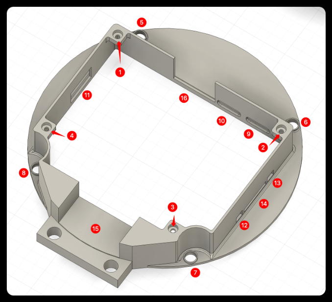
Head
![]()
❶❷❸❹: Magnet placement slot.
❺❻❼❽: Screw fixing hole.
❾❿: Type-c port.
⓫: USB port.
⓬⓭: Button port.
⓮: SD card port.
⓯: Wire channel.
⓰: Reserved space for camera interface.
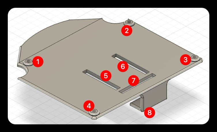
Head cover
![]()
❶❷❸❹: Magnet placement slot.
❺❻❼: Reserved slot for the female header of the main adapter board.
❽: Adapter board support, preventing the adapter board from deforming inward when the module is inserted.
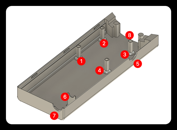
Handle back cover
![]()
❶❷❸❹: Coupling female socket.
❺: Knob reserved hole.
❻❼: Battery DC charging port support.
❽: Wire channel.
Overall effect
Front Side
![]()
Back Side
![]()
-
Sensor Selection for ESP32 P4-SensorCam P4
09/05/2025 at 02:00 • 0 commentsAfter completing the screen selection, we further planned the overall hardware design scheme for SensorCam P4, which roughly includes the following components:
The handle contains batteries. Next, I will elaborate on our selection considerations and final decisions regarding the mainboard, control components, power supply system, and other aspects.
1. Base Board
After the screen model was selected, we found that there were compatibility challenges between the ESP32P4 chip and the originally planned display screen. After evaluating various aspects such as the form, interface, and performance of the main board, we finally chose an ESP32P4 development board integrated with a 3.4-inch touch display screen as the core main board, as shown in the figure below:
This development board has the following advantages:
● Compact design: The core board is small enough to save valuable space.
● Rich interfaces: Provides a variety of peripheral interfaces with strong expandability.
● Communication capability: Onboard ESP32C6MINI module, supporting WiFi connection.
● Excellent display performance: 800×800 high resolution, 70% NTSC wide color gamut, 300cd/m² high brightness.
● Form fit: The shape design meets the ergonomic requirements of a handheld magnifying glass.
This motherboard not only solves compatibility issues, but its highly integrated design also greatly simplifies our system architecture and reduces the overall complexity.
2. knob
Why are physical knobs still needed in the touchscreen era? Because we recognize that for fine operations (such as image zooming, parameter adjustment, and menu navigation), the tactile feedback and precise control provided by physical knobs are difficult for touchscreens to replace. The knob we chose is the EC11, as shown in the figure below:
The EC11 knob has the following characteristics:
● Suitable size: The diameter and height conform to ergonomics, ensuring comfortable operation.
● Exquisite appearance: The metallic texture is consistent with the overall style of the device.
● High performance: High sensitivity and accurate scale feedback.
● Economy: Extremely high cost performance and stable market supply.
The EC11 knob will provide users with an intuitive parameter adjustment experience, and it performs exceptionally well especially in scenarios that require quick and precise adjustments.
3. Buttons
Although equipped with a touchscreen, we firmly believe that physical buttons still have irreplaceable value in specific scenarios: for quick operations, blind operation needs, and providing clear physical feedback.The buttons we chose are five-wire circular keyboard modules, as shown in the figure below:
The five-line circular keyboard module has the following advantages:
● Reasonable layout: The circular arrangement conforms to the natural movement trajectory of fingers.
● Excellent touch: The keys have a crisp sound and clear feedback.
● High sensitivity: Fast response with no sense of delay.
● Ergonomic design: The key travel and pressing force have been optimized, making it not easy to get tired during long-time operation.
These buttons will serve as a supplement to touch operations, providing users with more diversified options for interaction methods.
4. Battery
To meet the requirement of long-term use of portable devices, we have chosen a 5600mAh 5V lithium battery as the power solution for the following reasons:
● High energy density: 5600mAh capacity ensures that the device can work continuously for a long time.
● Stable output: 5V output voltage perfectly matches the device requirements.
● Reusable: Supports repeated charging and discharging, economical and environmentally friendly.
● High safety: Built-in protection circuit to prevent overcharging and over-discharging.
5. Summary
Our hardware selection follows the following principles:
● balancing performance and power consumption
● optimizing user experience
● and ensuring system stability.
The ESP32P4 development board serves as the core, combined with the EC11 knob, circular keyboard, and large-capacity lithium battery, together forming a complete and efficient hardware ecosystem. This design scheme not only meets basic functional requirements but also achieves a good balance in terms of interactive experience and portability. Next, we will design a suitable casing for the SensorCam P4 based on the form of these hardware components.
-
Interface/Base Board - Screen selection for ESP32P4-SensorCam P4
09/01/2025 at 07:20 • 0 commentsDuring the process of selecting a screen for the SensorCam P4, after our comprehensive evaluation and multiple rounds of testing, we finally selected two representative display screens:
Display A: 2.83-inch 480×640 resolution non-full lamination TFT-LCD screen, supporting 16.7M color display capability and touch function, with a 40pin 18-bit RGB+SPI interface.
Display B: 2.4-inch 240×320 resolution fully bonded TFT-LCD screen, supporting 263K color display, without touch function, using a 14-pin 4-wire SPI interface.
These two screens represent different product positioning: Display A is more excellent in terms of pixel density, color performance, and functional integrity; Display B has advantages such as low cost, easy procurement, and a narrow-bezel full lamination structure. Below, we will systematically compare their performance in parameters such as static and dynamic resolution, pixel density, brightness, color gamut, and refresh rate. Considering that the SensorCam P4 is mainly used indoors, we chose to conduct the test indoors.
Comparison of static display effects
It can be intuitively seen from the real-shot comparison chart the differences between the two screens in terms of pixel fineness and color reproduction (Display A is on the left, and Display B is on the right):
1.Display complex images to compare the detail expression between the two
It can be seen that Display A is significantly superior to Display B in terms of pixel density and edge sharpness, with stronger detail expression.
2.Display color-rich images to compare color display effects
It is obvious that the overall display effect of Display A is significantly more delicate and has richer color gradations.
3.Display the comparison of thermal imaging UI prediction screens
The performance of the two screens on such images is similar, with no obvious differences.
Dynamic display performance test
Display A:Supports MIPI interface, with stable and smooth frame rate performance, fully meeting dynamic display requirements.
Display B:
● When using the screen refresh function for color gradient testing, the frame rate can reach 63fps, which is basically smooth.
![]()
● There is obvious stuttering when running LVGL animations, and performance is limited when handling complex graphical interfaces.
![]()
Summary and selection suggestions
The comprehensive comparison results show that there is a significant gap between the two screens:
Advantages of Display A:
● Higher refresh rate and frame rate stability.
● Wider color gamut range and color expressiveness.
● Higher pixel density results in a delicate display effect.
● Support touch interaction functionality.
● Larger display area.
Advantages of Display B:
● Lower procurement costs.
● Simple interface, few occupied pins.
● Narrow bezel full lamination design.
Although Display A features a non-full lamination design and relatively wide bezels, these factors have limited impact on the actual user experience. Considering the high requirements of SensorCam P4 for display quality and user experience, we ultimately chose Display A as the screen solution for this project. Its excellent display performance and touch functionality will provide users with an interactive experience far superior to that of Display B, which is more in line with the project's positioning for high-quality visual presentation.
-
ESP32 P4 + Camera + Sensors = ?
08/22/2025 at 02:19 • 0 commentsDuring the development of AI cameras, we realized that the form of AI cameras is far more than just RGB or depth cameras. "Specialized cameras" such as single-point ranging and thermal imaging do not rely on complex image processing, yet they can directly capture key physical information like temperature and distance, providing us with a new perspective to observe the world. This inspired us: can we create a lightweight hardware device that makes these efficient sensing capabilities more user-friendly and directly integrates them with camera images or even AI detection results, thereby achieving a wide range of functions?
Based on this concept, we propose SensorCam P4 — a modular sensing device with a camera at its core. This device is based on the high-performance ESP32-P4 main control, and its core capabilities are realized through pluggable expansion backplanes. There is no need to reflash the firmware; you only need to insert the corresponding sensing module according to your needs to quickly expand the functions, such as:
- Insert a thermal imaging module, and you can real-time overlay or split-screen display thermal imaging images on the camera screen, automatically identify and mark abnormal areas such as high temperature/low temperature.
- Insert a laser ranging module, and the precise distance of the object as well as what the object is can be displayed in real-time on the screen.
- Insert temperature, humidity, and air pressure sensors to obtain and display environmental data.
- …
SensorCam P4 adopts a highly modular design, getting rid of the cumbersome drawbacks of traditional multi-sensor integration solutions and focusing on the in-depth integration of camera images and sensing data. The camera is no longer just "seeing colors"; it can also let you "see temperature", "see distance" and so on, making it easy to obtain multi-dimensional data. You can also customize and add various modules according to actual needs. The device can automatically identify the type of inserted sensor and load the corresponding exclusive UI interface. For example, in thermal imaging mode, you can choose to display in overlay or split-screen; in ranging mode, it displays values and aiming reference lines, etc. It looks roughly like this
Why choose ESP32 P4 as the main controller?
Because its characteristics are highly consistent with the core requirements of the device - efficiently processing camera data, handling AI tasks, and achieving sensor fusion - which is specifically reflected as follows:
1. Native camera and display support
- Equipped with a MIPI-CSI interface, it can directly connect to high-resolution camera modules to stably acquire image data.
- A native MIPI-DSI display interface that can directly drive MIPI screens to fully present the fused images.
2. Powerful processing capability and built-in AI capability
- Equipped with a 400MHz main frequency CPU, its performance is far superior to the previous generation of ESP32, and it can easily handle concurrent data from multiple high-speed sensors (such as cameras, thermal imaging).
- Built-in vector instruction set and AI acceleration unit, supporting efficient local AI inference, which can directly run machine learning models such as image recognition and target detection on the device side, providing intelligent underlying support for sensor fusion.
- Supports hardware graphics acceleration and scaling engine, which can efficiently complete image overlay, scaling and graphics rendering, significantly reducing CPU load.
3. Rich connectivity capabilities
- Provides various interfaces such as UART, SPI, I2C, and ADC with sufficient bandwidth, laying the foundation for simultaneous access to multiple modules such as ranging, thermal sensing, temperature and humidity.
- Supports Wi-Fi and Bluetooth 5.x, facilitating wireless data transmission, remote monitoring, and OTA firmware upgrades.
4. Mature development environment
- Based on the ESP-IDF framework, it features high development efficiency and a complete ecosystem, supporting mainstream AI inference frameworks and model conversion tools, significantly reducing the threshold for AI application development.
- The community is active, and extensive support can be obtained in terms of underlying drivers, complex UIs (such as LVGL), AI deployment, and sensor integration.
Next step plan
We believe that the SensorCam P4 can provide significant convenience in development, research, and engineering applications. Next, we will focus on advancing the following work:
- Complete the overall hardware selection.
- Design the equipment shell structure.
- Develop backplane expansion interfaces.
- Develop drivers and UI for the first batch of modules (such as cameras, laser ranging, thermal imaging).
- ...
Welcome to share your insights on this direction. Which sensors do you think have the most application potential when combined with camera images? We will continuously update the progress on the project page.
-
What kind of AI camera web interface do you want?
08/21/2025 at 05:47 • 0 commentsreCamera Monitoring Interface Product Research
This is both a research sharing post and a discussion topic. As Makers/consumers, what features do you want in a network monitoring interface? Feel free to leave a comment below, or provide suggestions in our community (https://github.com/Seeed-Studio/OSHW-reCamera-Series/discussions). If your suggestion is adopted, we will give you a product as a gift when reCamera is launched.
Motivation: As the first page users interact with reCamera, it should present a sufficiently clear, powerful, and interactive interface.
When users use smart AI cameras (or remote network cameras), what do they want to see from the interface?
Product Goals: Clarity, interactivity, replaceable and expandable functions, and result output information.
User Needs:
Why would users buy an AI camera instead of a traditional IPC?
What are the advantages of AI cameras?
More expandable? More tailored to their own needs? Able to intelligently identify and alarm?
Expandability is reflected in:
1. Detection models can be replaced and self-trained.
2. Detection logic can be customized, including defining event triggering logic and selecting detection areas.
3. Output results can be exported and easily integrated into developers' own programs.
Event triggering and alarming are important functions of surveillance cameras.
User needs in different scenarios:
Home users: Hope to detect abnormal situations at home in a timely manner through intelligent recognition, such as strangers breaking in, fire hazards, etc., and expect the interface to be simple and easy to operate.
Enterprise users: Need comprehensive monitoring of production sites, office areas, etc., requiring intelligent recognition of production violations, personnel attendance, etc., and hope to couple with the enterprise's own management system.
Developer users: Focus on the product's expandability and secondary development capabilities, hoping to replace detection models, self-train models, and integrate output results into their own programs.
Market Cases:
Most products from large companies are toB types, making it difficult for users to conduct secondary development.
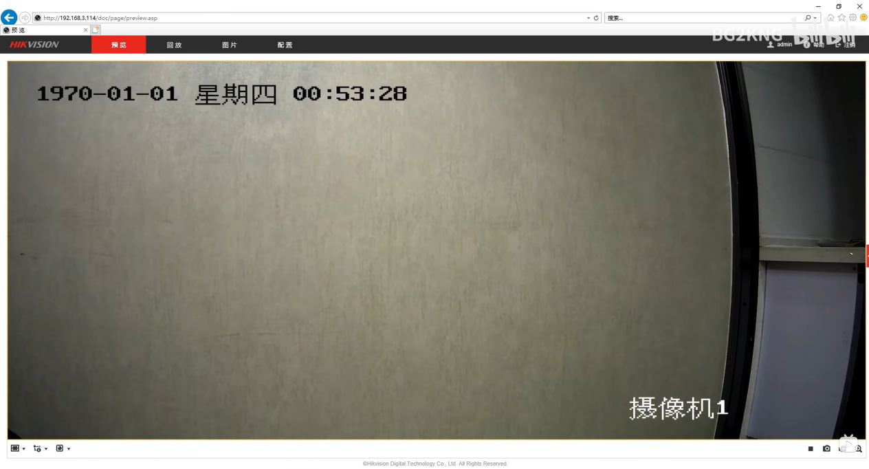
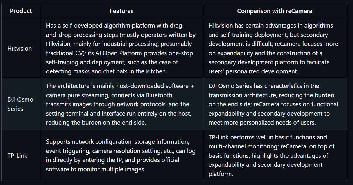
Hikvision Algorithm Platform:
Self-developed platform with drag-and-drop processing steps (operators written by Hikvision, mostly for industrial processing, presumably traditional CV). However, Hikvision's AI Open Platform provides one-stop self-training and deployment.
![]()
![]()
Hikvision AI Open Platform Case: Detection of masks and chef hats in the kitchen.
If we focus on expandability, providing a secondary development platform is crucial.
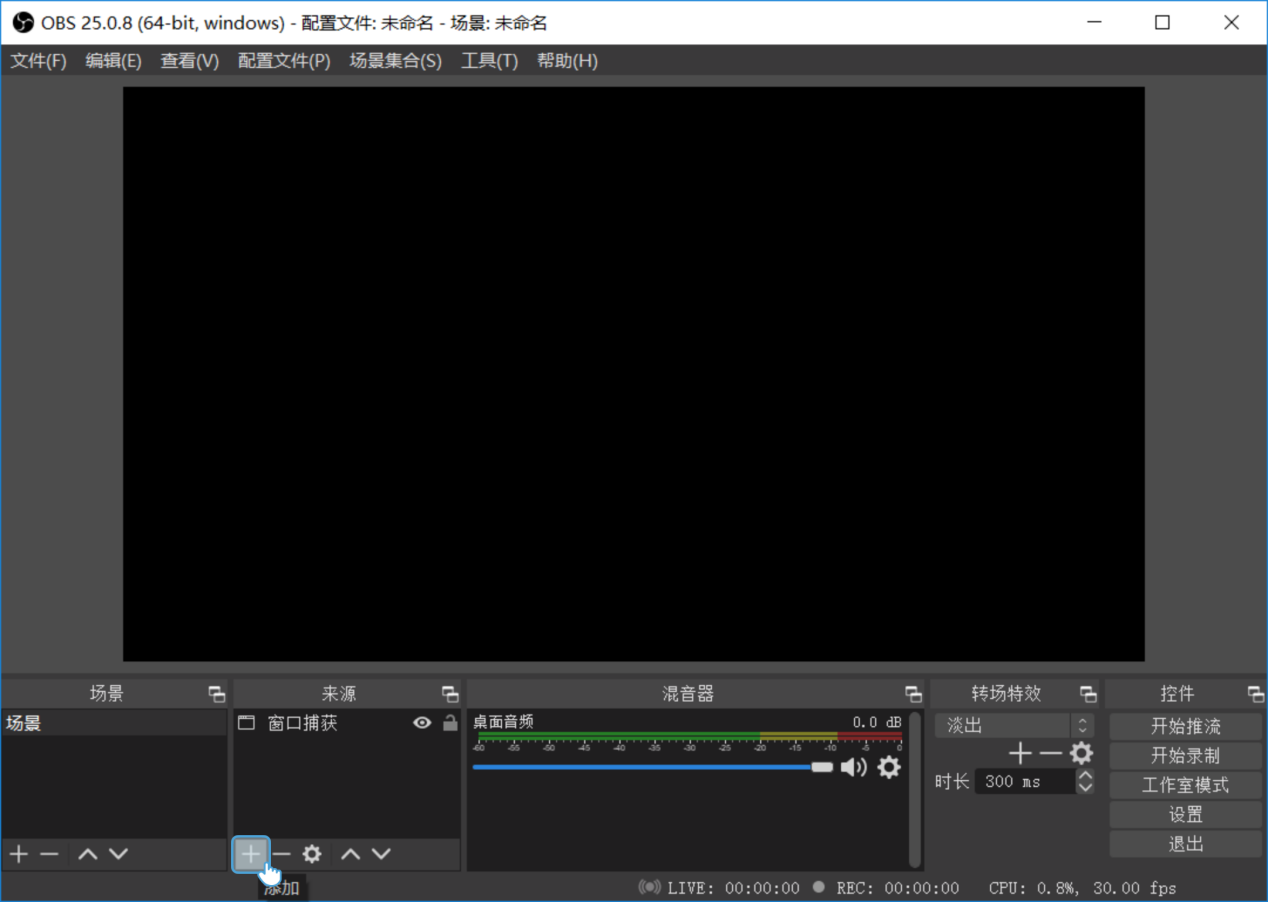
DJI Osmo Series:
The architecture is mainly host-downloaded software + camera pure streaming. It connects via Bluetooth and transmits images through network protocols, while the setting terminal and interface run entirely on the host, reducing the burden on the end side.
![]()
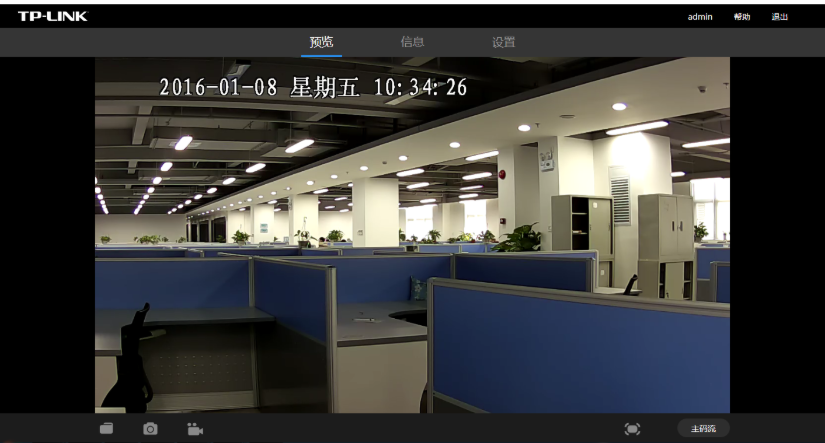
TP-Link:
Network configuration, storage information, event triggering, camera resolution.
Login directly by entering the IP.
![]()
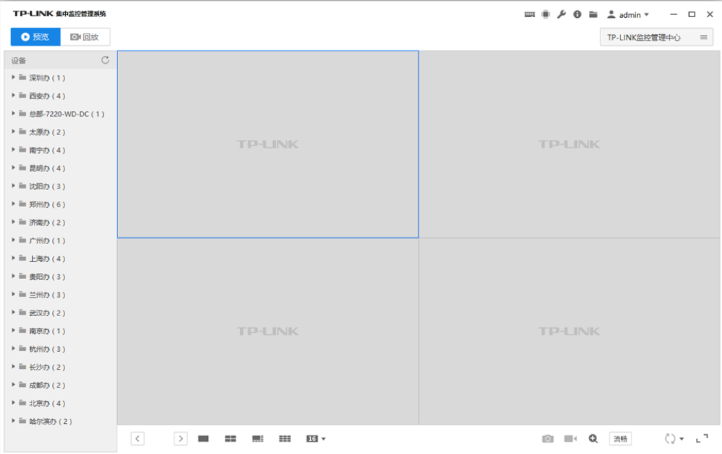
It also provides official software to monitor multiple images.
VCN 19 - Computer client remote monitoring method - TP-LINK Visual Security
![]()
Edge Computing Box - AI Algorithm Box - AI Edge Box - Kunyun Technology:
Supports SDK interfaces, mainstream frameworks such as PyTorch, customization, 4 Tops computing power, 4K@60fps, but more like re.
![]()
Content and Functional Requirements:
Functions marked in yellow are relatively rare or even non-existent in the market.
Basic Part:
- Video stream display (different code streams can be selected, low code stream has higher fluency)
- Display IP address and current time on the video screen
- Basic operation controls: pause/play, record, screenshot, audio switch, PTZ (this part is an extended function, linked with Gimbal) (pan-tilt control, direction keys + zoom slider (if available)).
Real-time annotation of AI recognition effects on the screen.
In fact, the monitoring website officially provided by RK has all these functions.
Device Parameter Settings:
Adjust resolution, bit rate, infrared night mode, smoothness, screen exposure and white balance (considering removing this part, as it seems redundant; although it can improve image quality, excessive adjustment may cause the screen to be unavailable), event triggering mechanism settings (done by RK but not tested successfully), etc.
Events defined by manufacturers lack custom interfaces.
Information Summary Center:
Specialized in information output, with timestamps, recording alarm information and detection results at each moment.
Add data output interfaces, which can be transmitted to external devices through protocols such as MQTT and HTTP.
Custom event triggering with low power consumption, supporting selected area detection.
What function in web side do you want? Please give your opinion and we will try our best to meet it.
-
Compatibility Testing - RV1126B - Adapt to the video analysis algorithm sharing of embedded devices
08/19/2025 at 07:01 • 0 commentsWhy Deploy Video Detection Models on Embedded Devices?
When we talk about visual AI, many people first think of high-precision models on the server side. However, in real-world scenarios, a large number of video analysis requirements actually occur at the edge: abnormal behavior warning of smart cameras, road condition prediction of in-vehicle systems... These scenarios have rigid requirements for **low latency** (to avoid decision lag), **low power consumption** (relying on battery power), and **small size** (to be embedded in hardware devices). If video frames are transmitted to the cloud for processing, it will not only cause network delay but also may lead to data loss due to bandwidth limitations. Local processing on embedded devices can perfectly avoid these problems. Therefore, **slimming down** video detection models and deploying them to the edge has become a core requirement for industrial implementation.
Isn't YOLO Sufficient for Visual Detection?
The YOLO series (You Only Look Once), as a benchmark model for 2D object detection, is famous for its efficient real-time performance, but it is essentially a **single-frame image detector**. When processing videos, YOLO can only analyze frame by frame and cannot capture **spatiotemporal correlation information** between frames: for example, a "waving" action may be misjudged as a "static hand raising" in a single frame, while the continuous motion trajectory of multiple frames can clarify the action intention.
In addition, video tasks (such as action recognition and behavior prediction) often need to understand the "dynamic process" rather than isolated static targets. For example, in the smart home scenario, recognizing the "pouring water" action requires analyzing the continuous interaction between the hand and the cup, which is difficult for 2D models like YOLO because they lack the ability to model the time dimension.Basic Knowledge of Video Detection Models: From 2D to 3D
A video is essentially four-dimensional data of "time + space" (width × height × time × channel). Early video analysis often adopted a hybrid scheme of "2D CNN + temporal model" (such as I3D), that is, first using 2D convolution to extract single-frame spatial features, and then using models like LSTM to capture temporal relationships. However, this scheme does not model spatiotemporal correlations closely enough.
**3D Convolutional Neural Networks (3D CNNs)** perform convolution operations directly in three-dimensional space (width × height × time), and extract both spatial features (such as object shape) and temporal features (such as motion trajectory) through sliding 3D convolution kernels. For example, a 3×3×3 convolution kernel will cover a 3×3 spatial area in a single frame and also span the time dimension of 3 consecutive frames, thus naturally adapting to the dynamic characteristics of videos.Why Introduce Efficient 3DCNNs Today?
Although 3D CNNs can effectively model video spatiotemporal features, traditional models (such as C3D and I3D) have huge parameters and high computational costs (often billions of FLOPs), making them difficult to deploy on embedded devices with limited computing power (such as ARM architecture chips).
The **Efficient 3DCNNs** proposed by Köpüklü et al. are designed to solve this pain point:
1. **Extremely lightweight design**: Through technologies such as 3D depthwise separable convolution and channel shuffle, the model parameters and computational load are reduced by 1-2 orders of magnitude (for example, the FLOPs of 3D ShuffleNetV2 are only 1/10 of ResNet-18) while maintaining high precision;
2. **Hardware friendliness**: It supports dynamically adjusting model complexity through "Width Multiplier" (such as 0.5x, 1.0x) to adapt to embedded devices with different computing power;
3. **Plug-and-play engineering capability**: The open-source project provides complete pre-trained models (supporting datasets such as Kinetics and UCF101), training/fine-tuning scripts, and FLOPs calculation tools, which greatly reduce the threshold for edge deployment.
For scenarios that need to implement real-time video analysis (such as action recognition and gesture control) on embedded devices, Efficient 3DCNNs can be called a "model of balance between precision and efficiency".- **Multi-model comparison and verification**:
The paper implements 8 types of 3D CNNs (including lightweight models and mainstream models such as ResNet-18/50 and ResNeXt-101) and conducts unified benchmark tests on datasets such as UCF101 and Kinetics. The results show that lightweight models (such as 3D ShuffleNetV2) perform best in balancing precision and efficiency. For example, on the Jester dataset (gesture recognition), its FLOPs are only 1/10 of ResNet-18, but the accuracy reaches 92.3%.## Test Analysis
First, let's look at the picture:![]()
First, we need to understand the performance of the test platform, which will provide a benchmark for future selection and adjustment.1. **Titan XP: Representative of High-performance Desktop GPUs**
NVIDIA's former flagship desktop GPU has powerful floating-point computing capabilities and memory bandwidth. It has a sufficient number of CUDA cores, a memory bandwidth of up to 336GB/s, and a single-precision floating-point performance (FP32) of **11.3 TFLOPs**. It can efficiently handle high-complexity 3D convolution calculations, provide sufficient computing power support for the model, and is suitable as a "performance upper limit" reference platform to verify the extreme performance of the model under ideal hardware conditions.2. **Jetson TX2: Pioneer in Embedded AI Computing**
Jetson TX2 is a platform for embedded and edge computing, focusing on low power consumption and lightweight deployment. It integrates an NVIDIA Pascal architecture GPU (256 CUDA cores), paired with a dual-core Denver 2 CPU and a quad-core ARM A57 CPU, with an overall power consumption controlled at 7.5 - 15W. Although its computing power (**FP32 is about 1.33 TFLOPs**) is much lower than that of Titan XP, it fits the "edge deployment"需求 in actual scenarios and is used to test the practicality of the model in resource-constrained environments.We hope that the video analysis algorithm can truly be implemented on our smart cameras, and **computational efficiency, real-time performance, and precision** are the two major issues we need to consider.
1. Computational Efficiency and Real-time Performance
Smart cameras usually hope to achieve a detection speed of at least 15fps (frames per second) to ensure the real-time performance of detection without obvious delay.
- **Titan XP platform**: From the table data, Titan XP has a very fast computing speed. For example, 3D - ShuffleNetV1 0.5x can process 398 video clips per second (cps) on this platform, and even the relatively heavy 3D - SqueezeNet can reach 682 cps. However, Titan XP is a desktop-level high-performance GPU with large size and high power consumption, which is not suitable for direct deployment in smart cameras. Therefore, although it can support the model to achieve ultra-high computational efficiency, it has little reference significance in the smart camera scenario from a practical application perspective.
- **Jetson TX2 platform**: Jetson TX2 is an embedded computing platform, which is closer to the hardware conditions of smart cameras. Some lightweight models can meet the real-time requirements on this platform. For example, the cps of 3D - ShuffleNetV1 0.5x is 69, the cps of 3D - ShuffleNetV2 0.25x is 82, and the cps of 3D - MobileNetV1 0.5x is 57. The processing speed of these models per second is higher than 15fps, enabling real-time detection. However, some models have low computational efficiency. For example, the cps of 3D - MobileNetV2 0.7x on Jetson TX2 is only 13, which cannot meet the real-time requirements.2. Model Precision
When smart cameras are used for real-time detection, they need high precision, otherwise, there may be more false detections and missed detections, reducing the reliability of detection.
- On the Kinetics - 600 dataset, some lightweight models such as 3D - ShuffleNetV2 2.0x have an accuracy of 55.17%. Although there is a gap compared with some heavy models (such as ResNeXt - 101 with 68.30%), considering the limitation of computing resources, this accuracy can already meet some smart camera application scenarios with not extremely high precision requirements, such as some simple behavior classification and detection.
- On the Jester dataset, the accuracy of 3D - ShuffleNetV2 series models is generally high. For example, 3D - ShuffleNetV2 2.0x reaches 93.71%, and 3D - MobileNetV2 series can also reach about 86% - 93%. In scenarios such as gesture recognition, such accuracy can more accurately identify different gesture actions, providing reliable support for applications such as intelligent interaction.
- On the UCF - 101 dataset, the model accuracy can also meet certain actual needs. For example, the accuracy of 3D - ShuffleNetV2 2.0x is 83.32%, which can effectively identify various actions for applications such as human action recognition.Back to the RV1126B platform, its NPU computing power can reach 3Tops@INT8. Its real-time performance and power consumption may be better than those of Jetson TX2, but the accuracy will also decrease to a certain extent. 3D CNNs are models with high computational complexity. According to the test results, Jetson has achieved an accuracy of more than 76% on the two relatively simple action datasets Jester and UCF-101. Even if there is a certain loss in the quantized model running on the RV1126B platform, I believe that through targeted training and fine-tuning, the Efficient 3D algorithm can still complete video analysis tasks.
However, the biggest difficulty lies in platform adaptability. The NPU of RV1126B only supports model files in rknn format. At present, the official has not provided a tool to convert the model files of Efficient 3D into rknn format, which means that developers need to design operators and do platform adaptation, which is also the work that reCamera may do in the future.
In general, RV1126B can support the Efficient 3D video analysis algorithm in terms of computing power and performance, but more work needs to be done on platform adaptability.
-
Demo - RV1126B People Counting
07/24/2025 at 06:26 • 0 commentsIn retail stores, exhibition halls, and other scenarios, real-time grasp of the number of people entering the store and customers' stay time is the core basis for optimizing operation strategies. Based on the RV1126B edge computing platform, we have built a lightweight people flow detection Demo - through camera capture and local processing, to achieve accurate passenger flow counting and stay analysis. More importantly, the technical logic of this solution is deeply bound to the application scenarios, ensuring both detection accuracy and adaptation to actual operational needs.
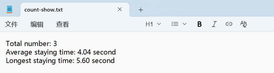
Display of Detection Results:
Generate Statistical Result Text
![]()
Core Logic: How to Make Cameras "Understand" People Flow?
The core idea of this Demo is to let the system "observe - judge - record" like the human eye, which is specifically divided into three steps:
Step 1: Accurately identify people in the picture
After the camera captures the frame in real-time, the system will first filter out the target of "people" - through a pre-trained YOLO 11 model, eliminate irrelevant objects such as goods and shelves, and only focus on the human contour. Even if the light is flickering (such as backlight at the store entrance, exhibition hall lighting switching), the system can still stably track pedestrians, ensuring that there will be no missed viewing or misjudgment due to light problems.
Step 2: Track the movement trajectory of each person
After identifying the portrait, the system will assign a "temporary ID" to each person and track their movement path in real-time. For example, when someone walks in from the door, the system will mark "enter" and start timing. It is worth mentioning that the tracking algorithm has done ID storage processing. Even if the target is lost, when it reappears in the picture, the system will not count repeatedly, but only continue timing, thus avoiding the disadvantage of traditional infrared sensors that "record once when blocked".
Step 3: Automatically record the stay time
When a person enters the monitoring area, the system will automatically start timing until they leave the area. At the same time, it will count data such as "average stay time" and "maximum stay time", which are of great practical value. For example, in retail scenarios, it can show how long customers stay in front of which shelves; in exhibition halls, it can analyze which exhibition areas are the most attractive. The timing logic does not rely on network time, but is accurately calculated based on the frame rate of the picture, ensuring that even if the network is disconnected, it can be accurately recorded.
Solution Features
Local processing, faster response
All calculations (recognition, tracking, timing) are completed on the RV1126B chip and do not need to be transmitted to the cloud. This means lower latency, and there will be no data lag due to network cotton, which is particularly important for stores that need to adjust manpower in real-time.
Flexible adaptation to different scenarios
The system has built-in adjustable "confidence parameters": in crowded supermarkets, the recognition threshold can be increased to avoid misjudgment when crowds are crowded; in boutiques with fewer customers, the threshold can be reduced to ensure that every customer entering the store is recorded. At the same time, we can also set "effective areas" (such as only counting people entering the store, ignoring pedestrians passing by the door), which can be adapted to the layout of different venues through simple configuration.
Two deployment methods, choose as needed
According to different needs, two implementation paths are provided:
- If you need to quickly test the effect, you can run it in Python script mode, complete the configuration within a few minutes, which is suitable for makers to quickly verify ideas;
- If you pursue long-term stable operation, you can cross-compile based on C++ language to generate efficient execution files, reduce power consumption and improve continuous working ability, which is suitable for unattended store scenarios.
Future Application Scenarios
The ultimate value of this Demo is to transform AI cameras into directly applicable operation tools:
For retail stores
- Automatically count "peak hours" (such as 18:00-20:00 on weekdays with the largest number of people), helping store managers arrange shifts reasonably;
- Analyze "popular area stay time", for example, if it is found that customers stay in front of a new product for an average of 5 minutes, the display intensity of this area can be increased.
For exhibition halls
- Quickly compare the passenger flow data of different exhibition areas, judge which types of exhibits are more popular, and provide a basis for the layout of the next exhibition;
From the perspective of technical logic, the core of this solution is "solving practical problems with the lowest cost" - without relying on complex server clusters, only through the local computing power of RV1126B, real-time collection and analysis of passenger flow data are realized. For developers, this logic can be directly reused: whether it is adjusting the recognition area or adding multi-camera linkage, it can be quickly expanded based on the existing framework, so that technology can truly serve scenario needs.
Peek Under the Hood: How to Build an AI Camera?
Log by log: See how we build reCamera V2.0! Platform benchmarks, CAD iterations, deep debug dives. Open build with an engineer’s eye view!