Mark Makies
-
Traction Troubles
06/17/2025 at 01:22 • 0 commentsWith the boost in torque and power, and thanks to some wet, slippery and soft ground, we hit a new problem: loss of traction.
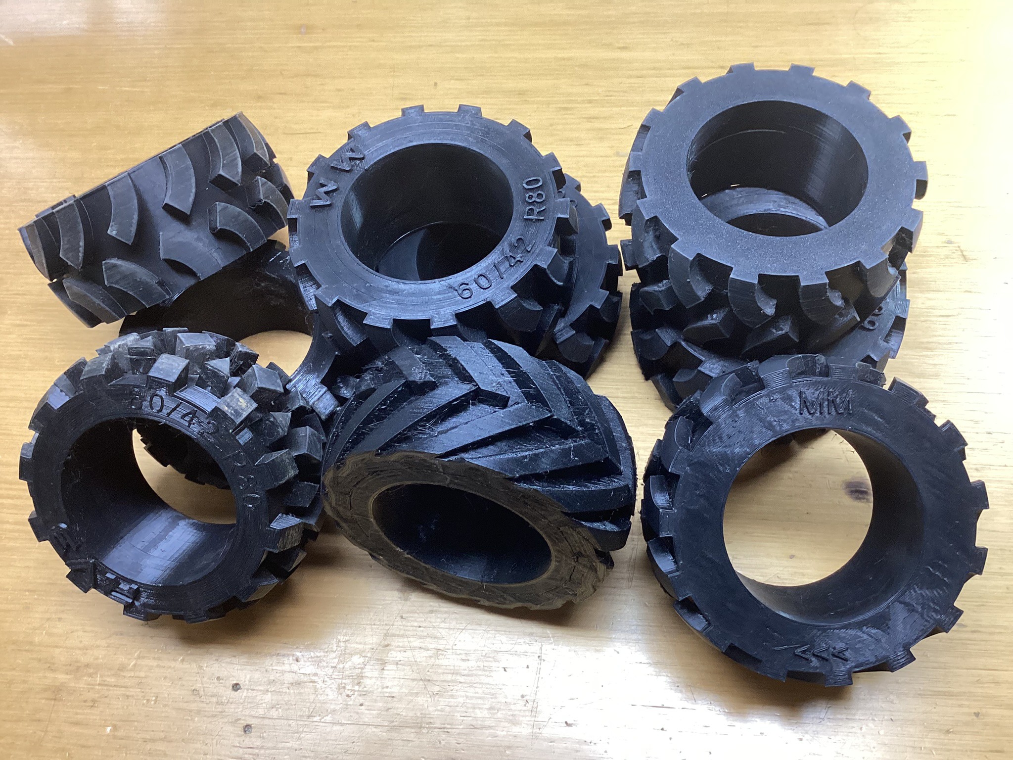
![]() I’ve never designed tyres before, so I took inspiration from tractor treads, then trail bike knobbies and then some kind of hybrid. All versions were 3D-printed in TPU for flexibility, but none of them could reliably grip the soft and slippery terrain.
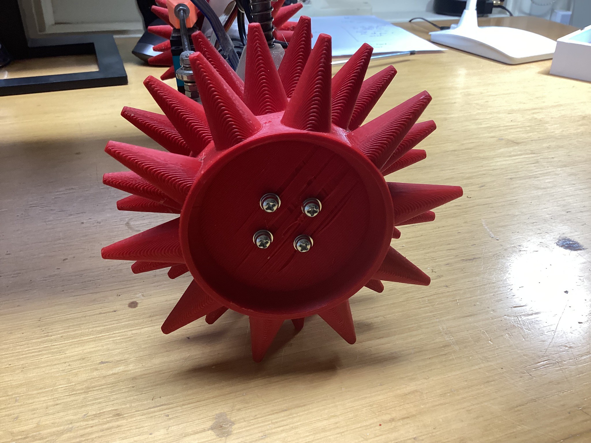
I’ve never designed tyres before, so I took inspiration from tractor treads, then trail bike knobbies and then some kind of hybrid. All versions were 3D-printed in TPU for flexibility, but none of them could reliably grip the soft and slippery terrain.Eventually running shoes with spikes inspired me. My latest attempt swapped TPU for PLA and used spike-like lugs. These actually worked... for a little while.
![]()
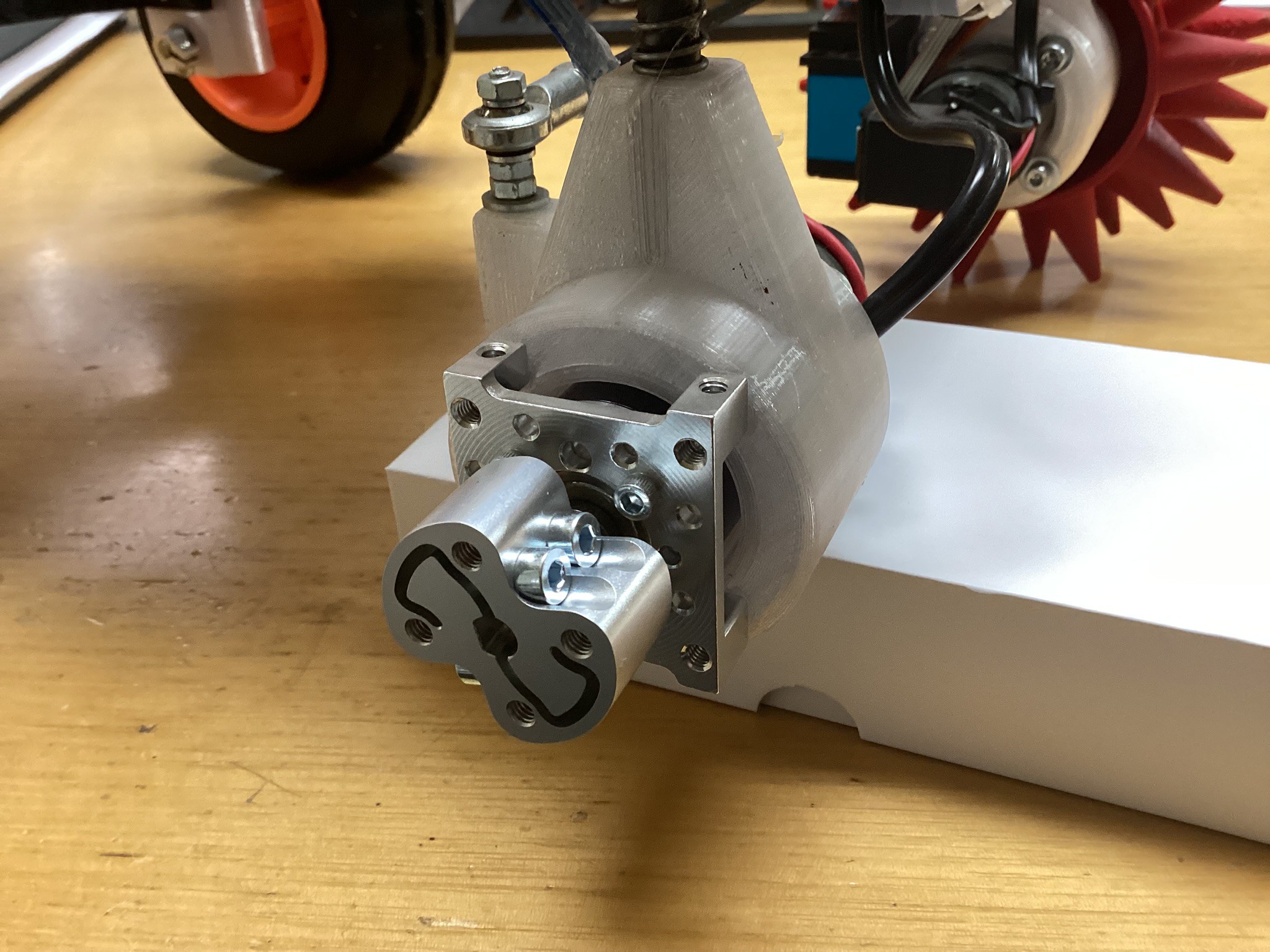
Unfortunately, the PLA hub, secured with a set screw on the motor shaft flat, failed under load. The keyway distorted and then melted/softened and then the wheels fell off!
To solve this, I found a proper metal hub adapter from the GoBilda range. These provide a much stronger interface between motor and wheel and allow easy, secure mounting going forward.
![]()
![]()
![]()
Now, just have to wait until the rain stops for further testing.
-
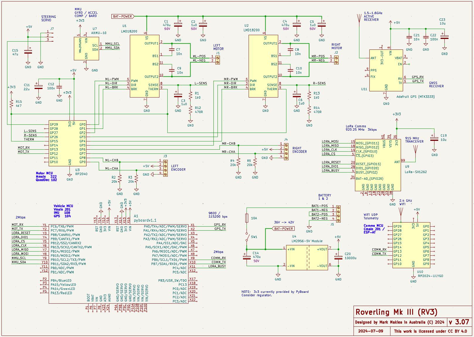
Electronics Upgrade (v2.03 → v3.07)
06/12/2025 at 23:27 • 0 commentsWith the project now focused on a specific application, autonomous metal detection, the electronics have been optimised for reliability, modularity, and expanded I/O.
-
Retaining the RP2040 for motor control PID and encoder feedback.
-
Adding a new Wi-Fi Comms Processor:
LilyGO T-PicoC3 (RP2040 + ESP32-C3) with 240×130 display. (using ESP-AT) -
Removing the RC module which was mainly used for testing.
-
Replacing the Vehicle Controller MCU (previously an RP2040) with a Pyboard v1.1 to accommodate expanded I/O needs:
-
UART to Motor MCU (2 pins)
-
UART for GPS (2 pins)
-
UART for Wi-Fi (2 pins)
-
SPI + GPIO for LoRa (7 pins)
-
I2C for IMU (2 pins)
-
-
Upgrading the main power supply from 20 V to 40 V to increase torque due to heavier payload.
![]()
Melt Down:
With increased torque and payload come new challenges, like spinning wheels and stalled motors. During an autonomous run, a stick got caught in one of the drive wheels (note to self: no more holes in wheels). The PID controller did what it was told, increased power to full and held it there. The result - One melted motor. I'm just lucky I had one spare.
40 V of Li-Po power pumped into a 24 V, 11 W brushed DC motor is far from iideal.
To prevent that from ever happening again, I’ve added both stall and slip detection:
Stall Detection:
Implemented at the motor controller (RP2040), this monitors current draw on each motor. If current exceeds a defined threshold continuously for more than a defined period (indicating a jam or blocked wheel), the controller shuts down motor output and reports the fault via UART to the vehicle controller. This is then passed on to the telemetry system.
Slip Detection:
Implemented at the vehicle controller (Pyboard), this compares expected movement (based on active commands) to actual displacement measured via GPS. If Roverling moves less than 1 m over 10 seconds while the motors are engaged and GPS fix is good, it transitions into a slipping state and halts further motion.
-
-
Navigation System Development
06/12/2025 at 06:25 • 0 commentsRoverling’s first level of navigation control uses a magnetometer. It’s initially calibrated offline using all three axes (for spherical remapping), and then recalibrated on Roverling itself with a figure-of-eight manoeuvre to correct for hard and soft iron effects.
However, the magnetometer is only accurate when the device is level. That becomes a problem when Roverling drives up, down, or across slopes. To compensate, tilt correction is applied using pitch and roll, which are calculated from a three-axis accelerometer.
Unfortunately, this solution is limited: the accelerometer provides reliable pitch and roll data only when stationary. On rough terrain, movement-induced spikes render the data unreliable.
The next level of control comes from GPS. While useful, it has its own limitations:
- Updates are only available once per second.
- Reported precision is ~18 cm.
- Real-world accuracy (after acquiring ~20 satellites and allowing 15 minutes to stabilise) is closer to 50 cm.
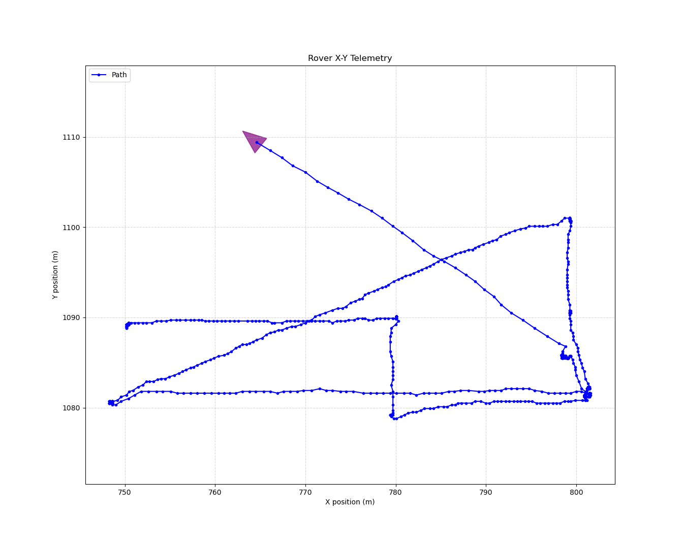
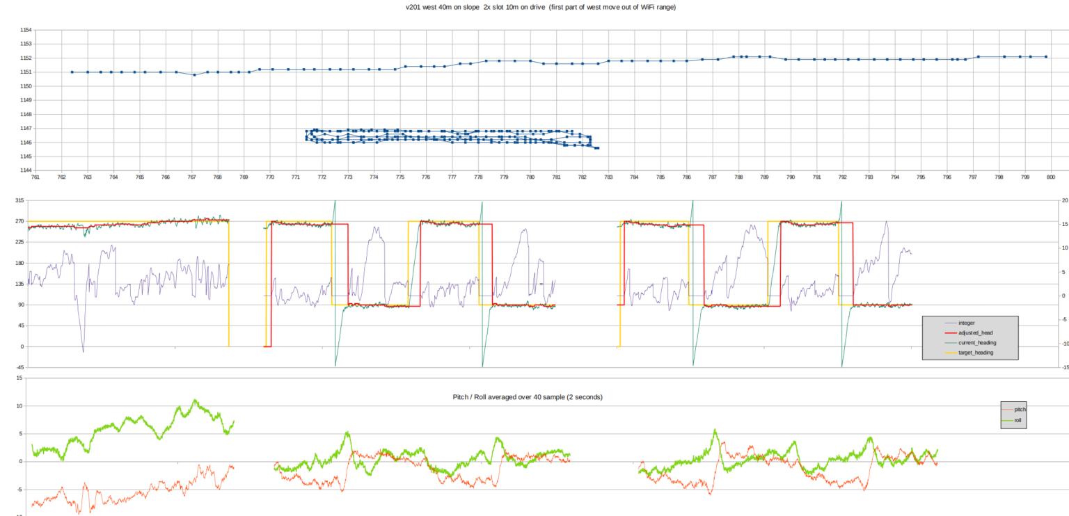
The first chart below (1 m/div) shows Roverling’s position during a fully autonomous (very slow) run:
- A 40 m straight line across a 10° slope: Roverling stays within a 1 m corridor.
- A series of tight 10 m slots on flat ground: again, deviations remain under 1 m.
That’s probably accurate enough to return to a previously detected object (e.g., a buried treasure).
The second chart tracks internal PID parameters as the vehicle drives back and forth.
![]()
So far, so good. For the next test, I suspended a string line overhead to check drift. Roverling ran autonomously using only the magnetometer for navigation. Still good.To test the complete system in a real-world scenario, I ran Roverling on a sloping, slightly rough paddock - typical of our bush block. This was a fully autonomous run, executing a predefined grid search pattern.
To support this, I developed:
-
a command-line utility to generate a rectangular search pattern in Roverling’s PlayList format (used directly by the vehicle),
-
a simulator to preview the planned route and detect any logic errors before deploying,
-
a visual overlay tool that displays both the planned simulation path and real-time telemetry - useful for live monitoring and post-run analysis.
Once everything was configured, I loaded the playlist, positioned Roverling at the start point, and let it go.
![]()
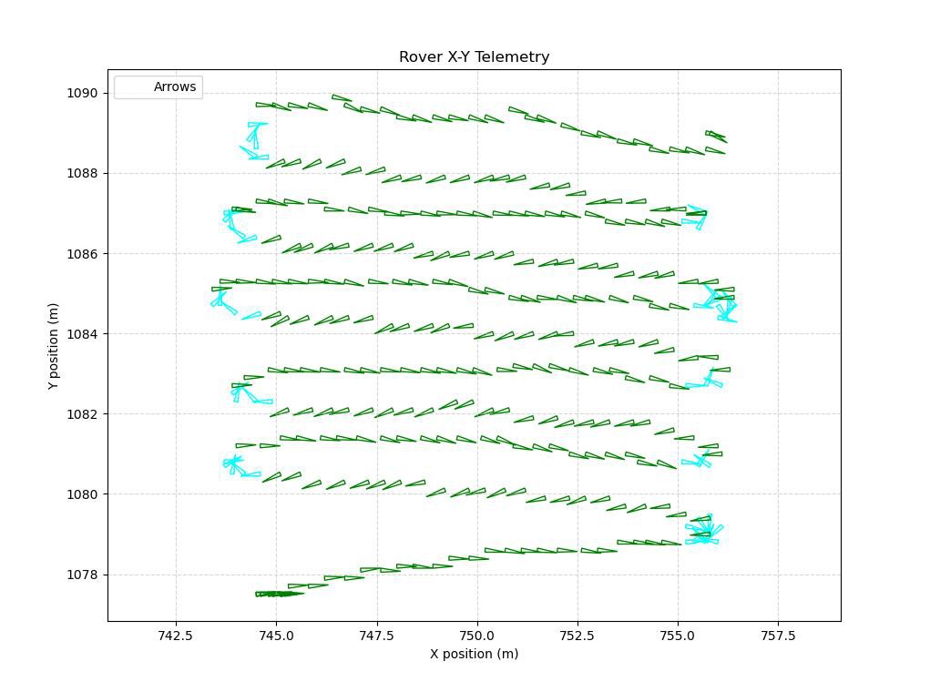
I was hoping for so much more. This test was conducted across a slope, which affected both GPS and compass data. The next chart shows the same path as before. The heading arrows are derived from the magnetometer.
![]() Observations:
Observations:- Compass heading is not entirely trustworthy when operating on bumpy ground despite pitch/roll compensation.
- GPS position drifts.
- Wheel encoders can’t be used either - too much slipping for reliable dead reckoning.
Solution:
Enter the Madgwick Filter: a lightweight, efficient sensor fusion algorithm that can run in real-time on an RP2040. I implemented it in Python to combine data from:
- Gyroscope (short-term orientation stability)
- Accelerometer (gravity direction)
- Magnetometer (absolute heading)
to estimate orientation (pitch, roll, yaw [aka heading]) in full 3D.
It was not easy to code - but it works brilliantly.
The final chart shows Roverling executing a straight-line autonomous path using the Madgwick-derived heading. Early signs are very promising.
Now, once the weather fines up, back to testing
![]()
-
Power Upgrade
06/11/2025 at 08:04 • 0 commentsPower supply upgraded from 20V to 40V for the additional torque required to tow the Metal Detector trailer up the hills. But with this additional power comes speed, so let’s give the controls to a 6 year old to test stability….
Roverling Mk II
Autonomous robot with GPS + IMU navigation, waypoint execution, PID control, RC + LoRa + Wi-Fi comms and real-time telemetry.
 I’ve never designed tyres before, so I took inspiration from tractor treads, then trail bike knobbies and then some kind of hybrid. All versions were 3D-printed in TPU for flexibility, but none of them could reliably grip the soft and slippery terrain.


 Observations: