 Jorisclayton
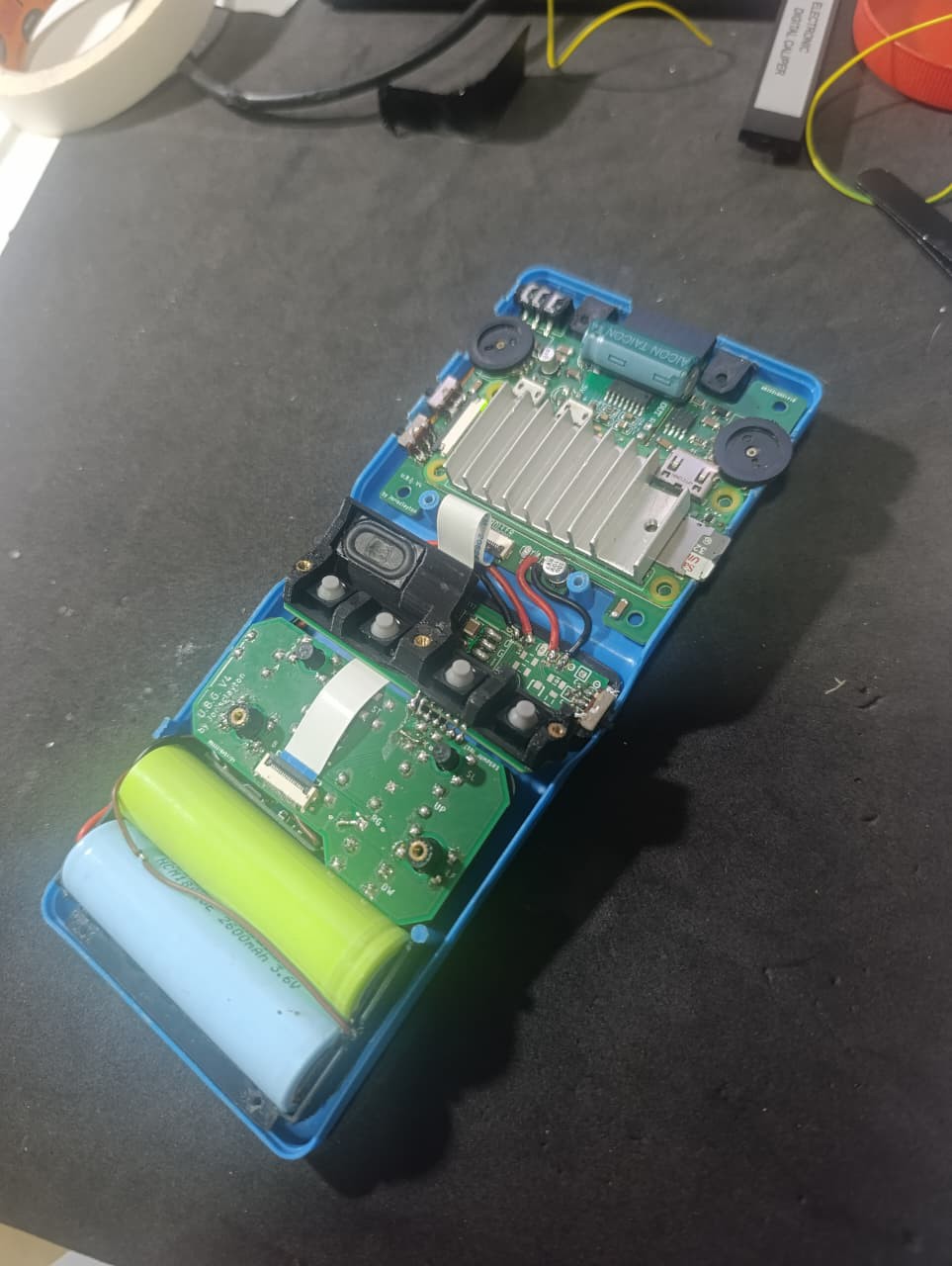
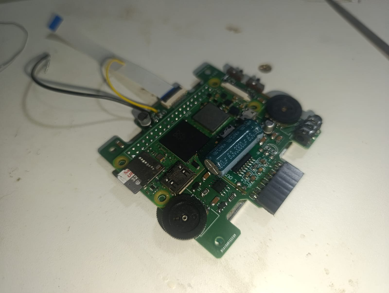
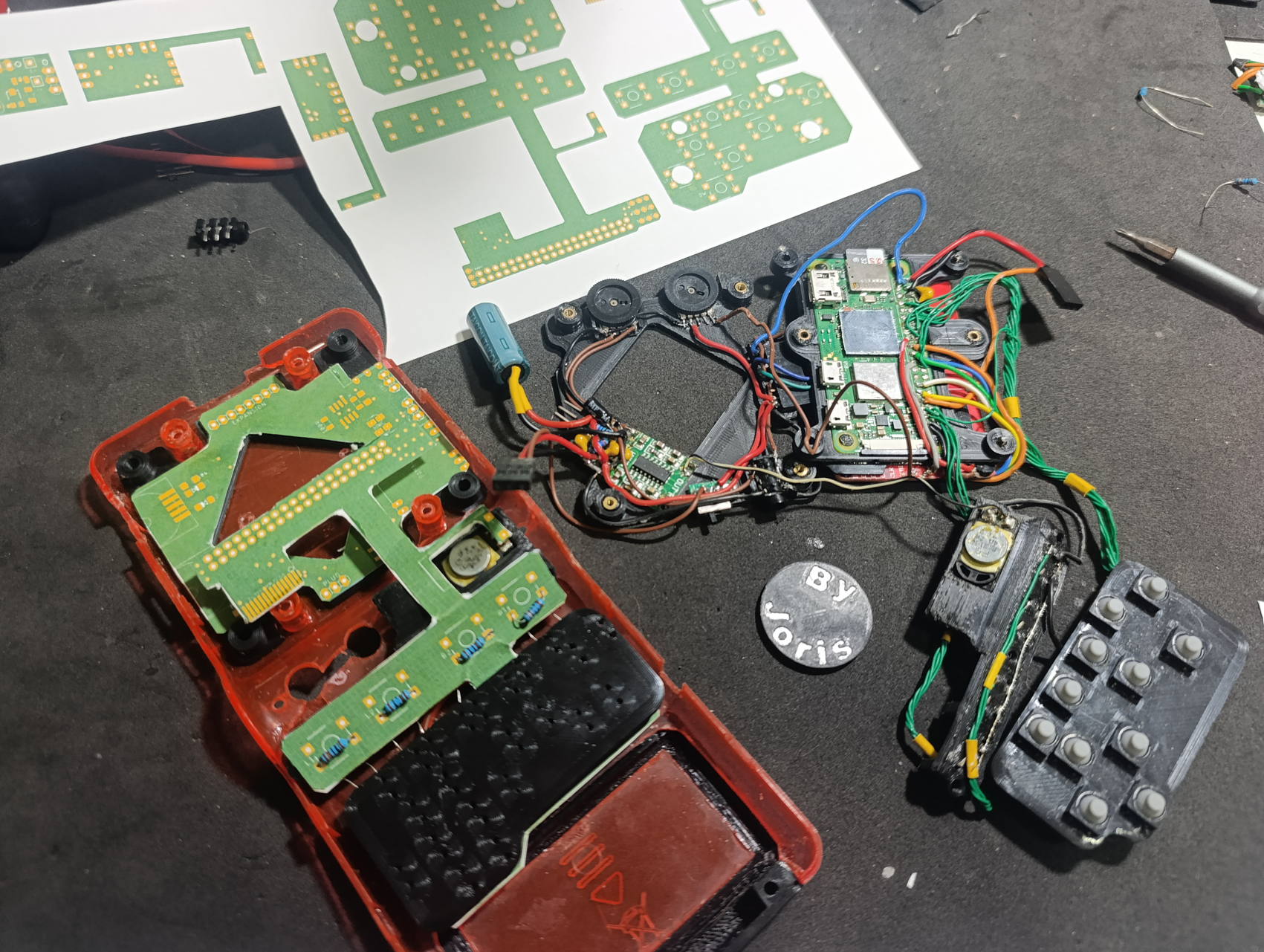
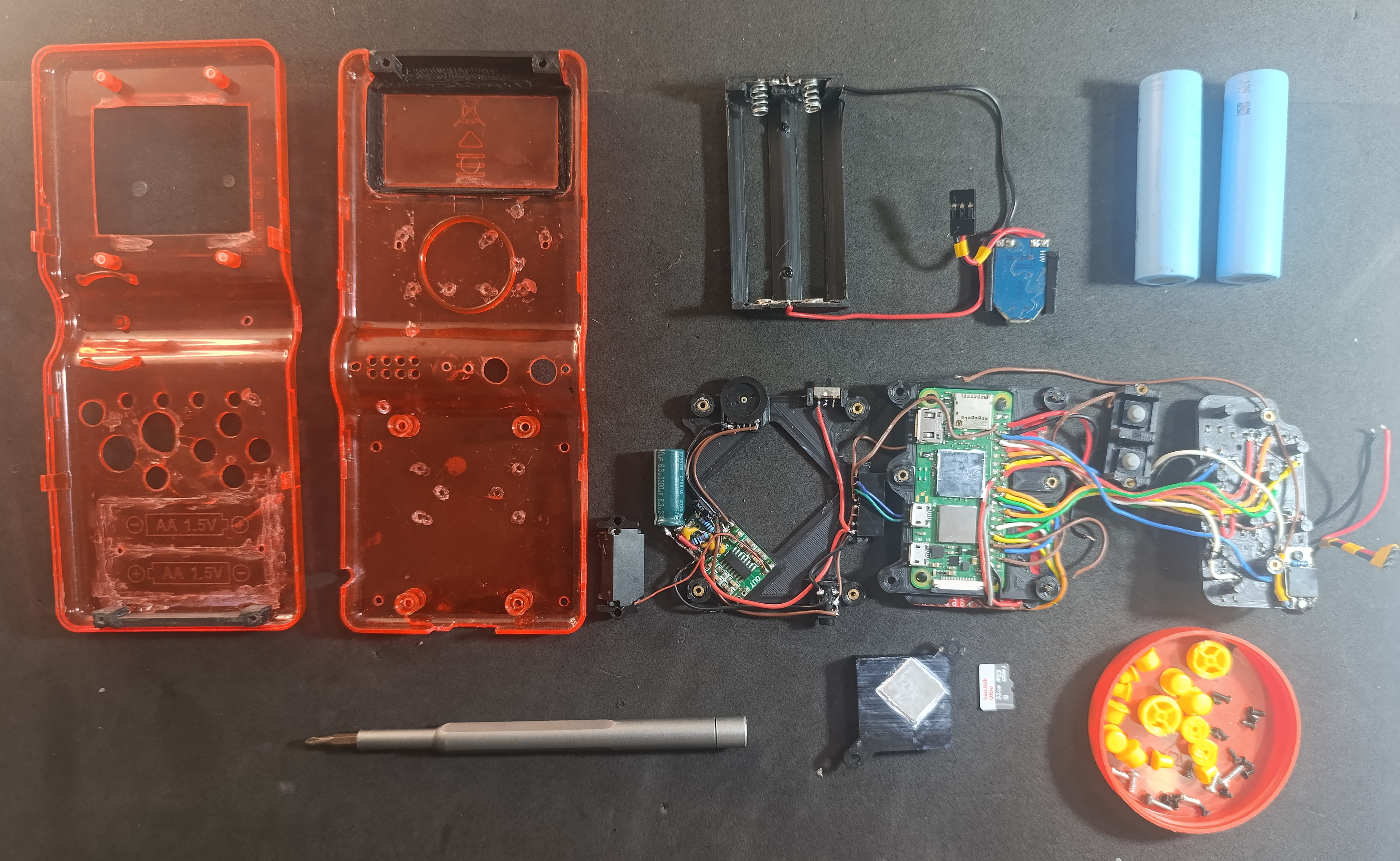
- Powered by a Raspberry Pi Zero 2W
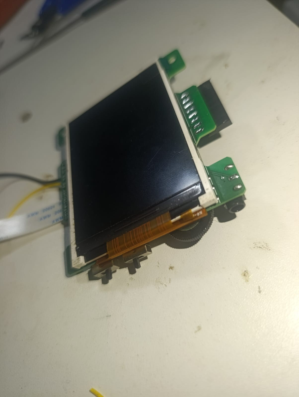
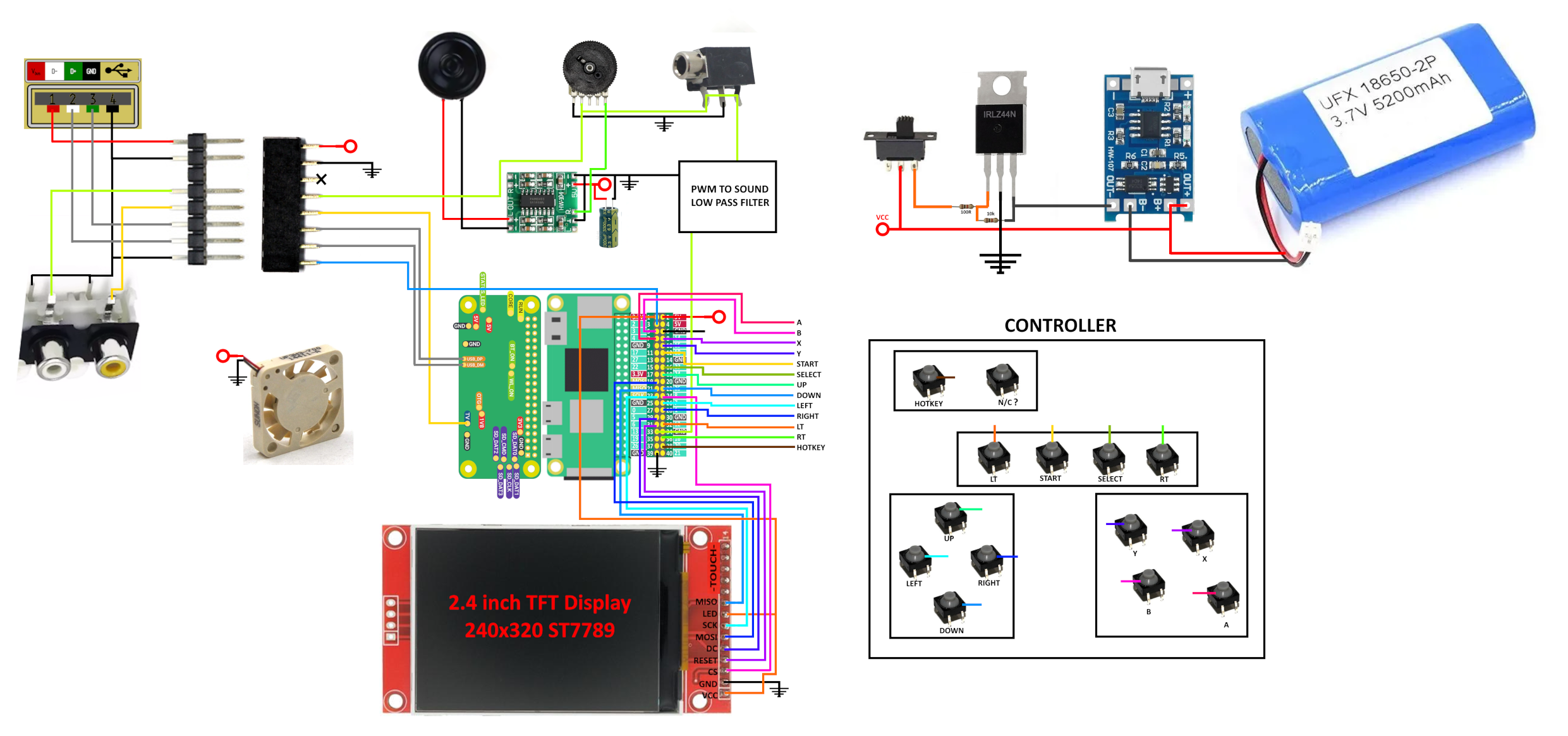
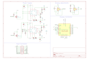
- 2.8" or 2.4" SPI TFT display (ST7789) with 320x240 resolution and PWM brightness controller.
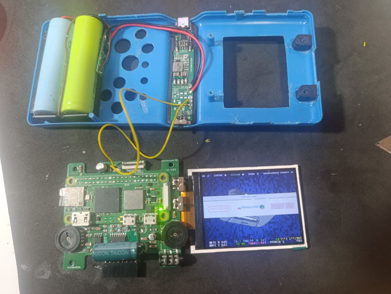
- Two 2400mAh 18650 cells in serie (2S 8.4 Volts).
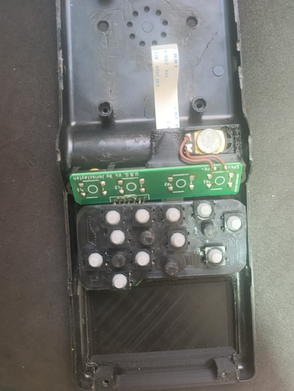
- PAM8403 module using a notebook speaker.
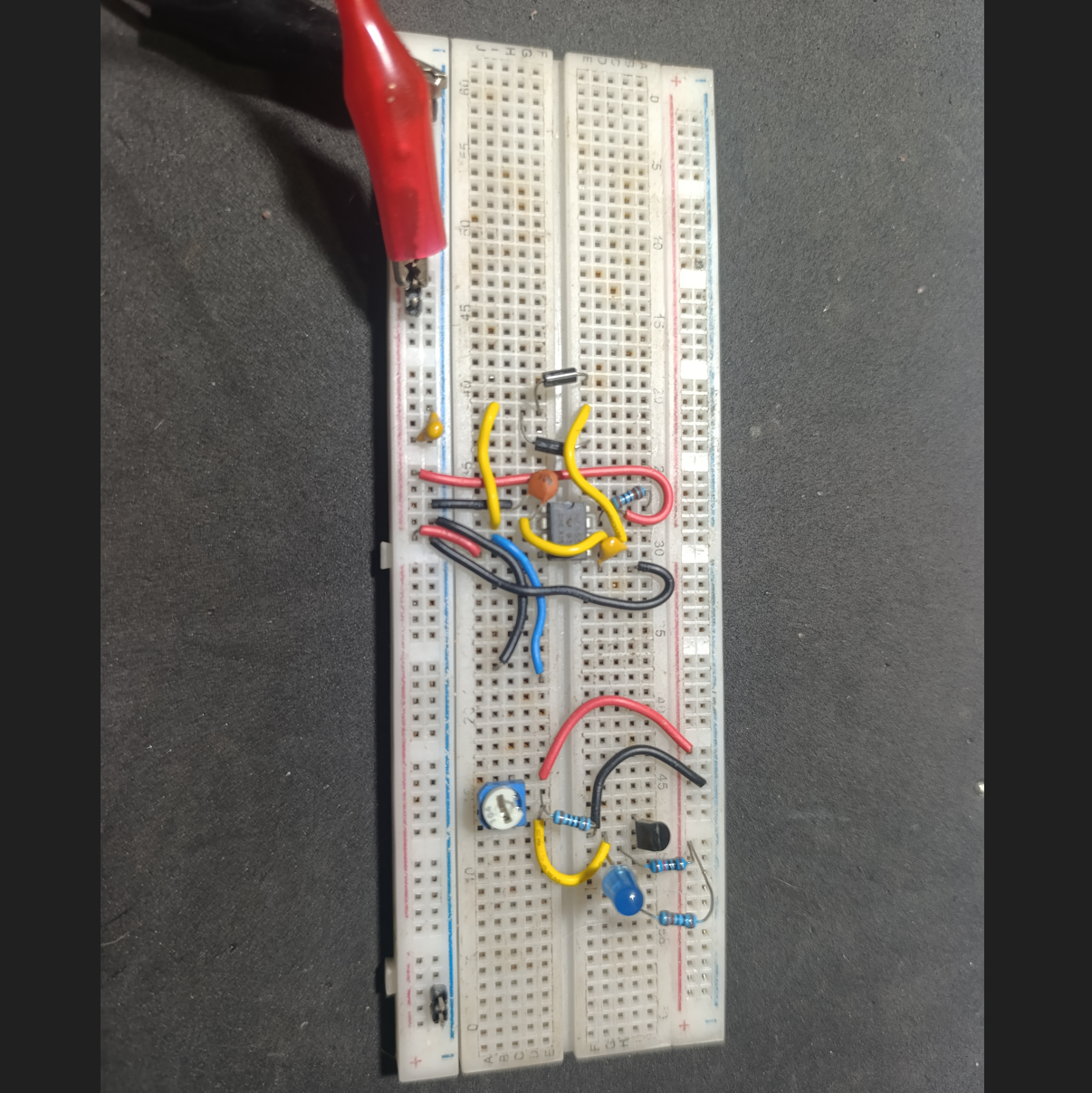
- Custom low-pass audio filter transforms the Pi’s PWM output into proper audio.
- Added a 3.5mm headphone jack and a volume knob.
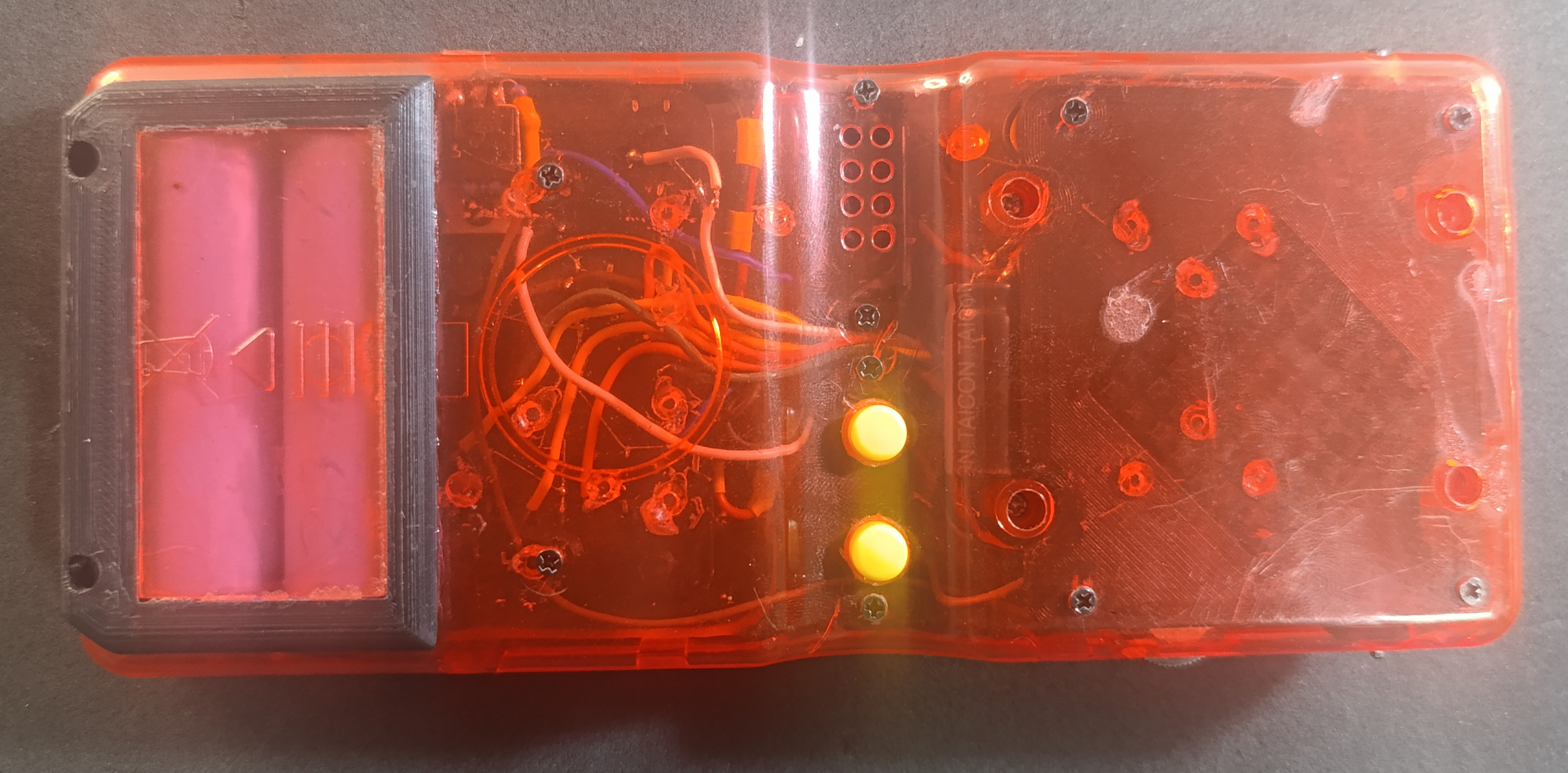
- RCA video output wired to the top of the console.
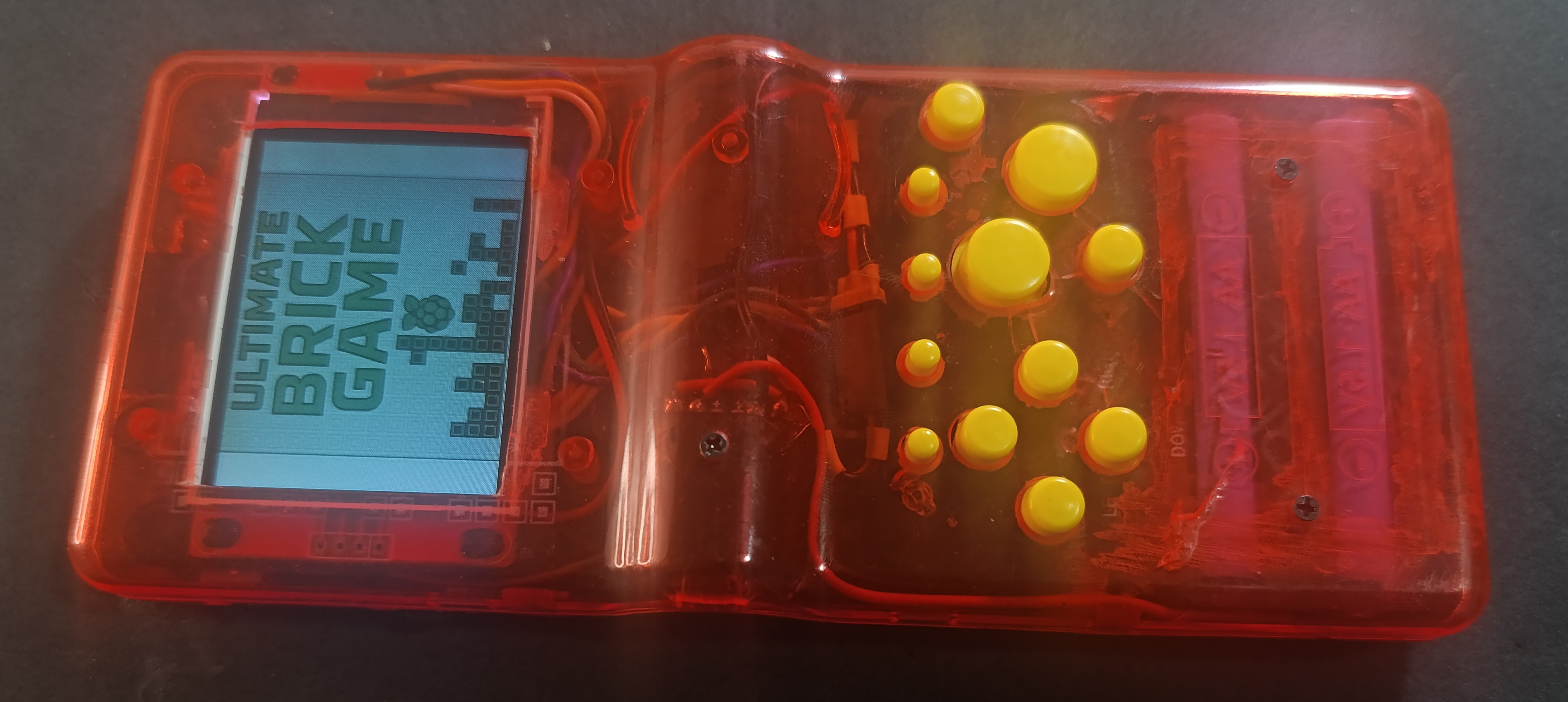
- Front panel includes extra buttons for X, Y and four rear buttons (L/R-style).
- All parts held in place with 3D-printed supports, M2 brass inserts, and machine screws.
- Bluetooth controller support and Wi-Fi enabled.
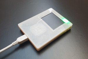
- Can charge while playing.
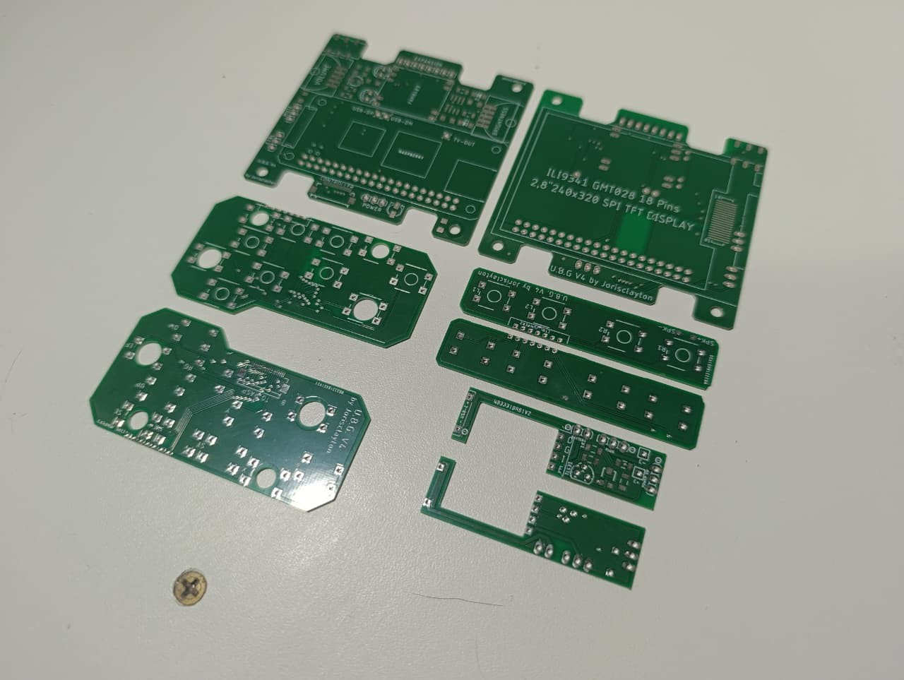
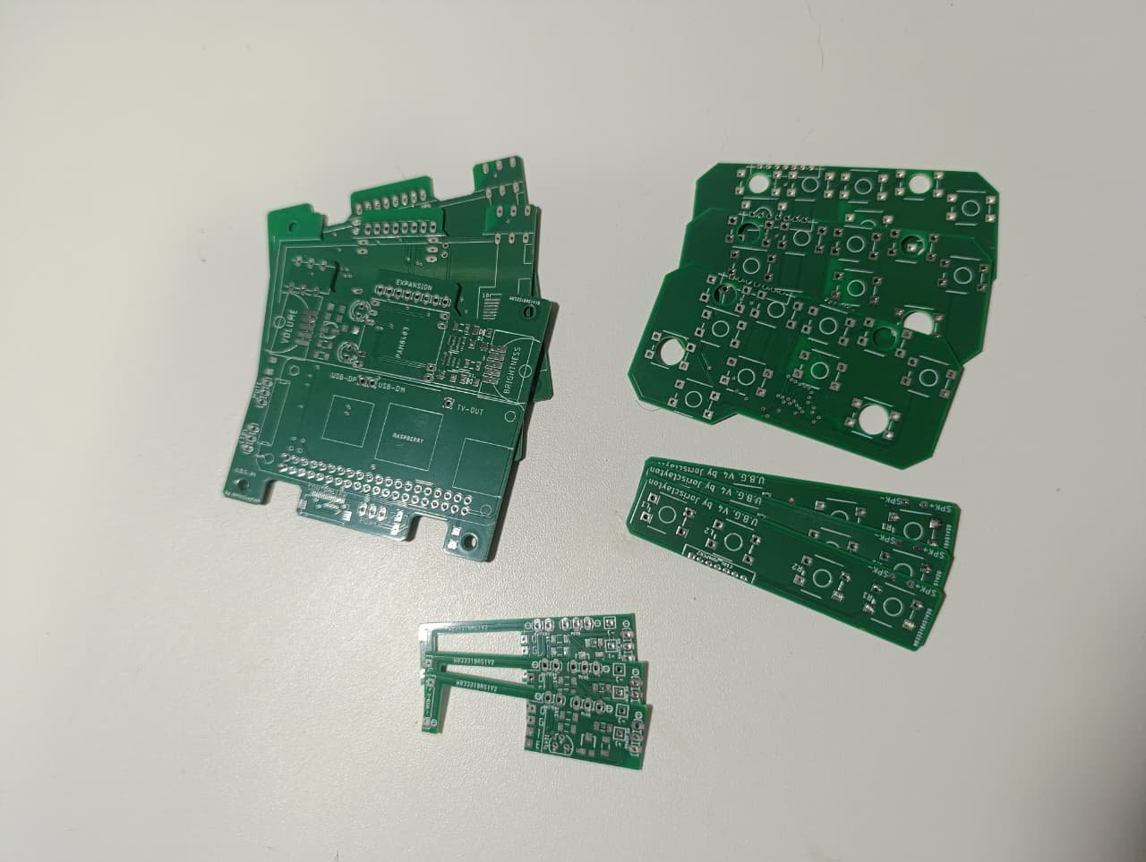
- Has its own PCBs to avoid wiring a lot.
0%
0%
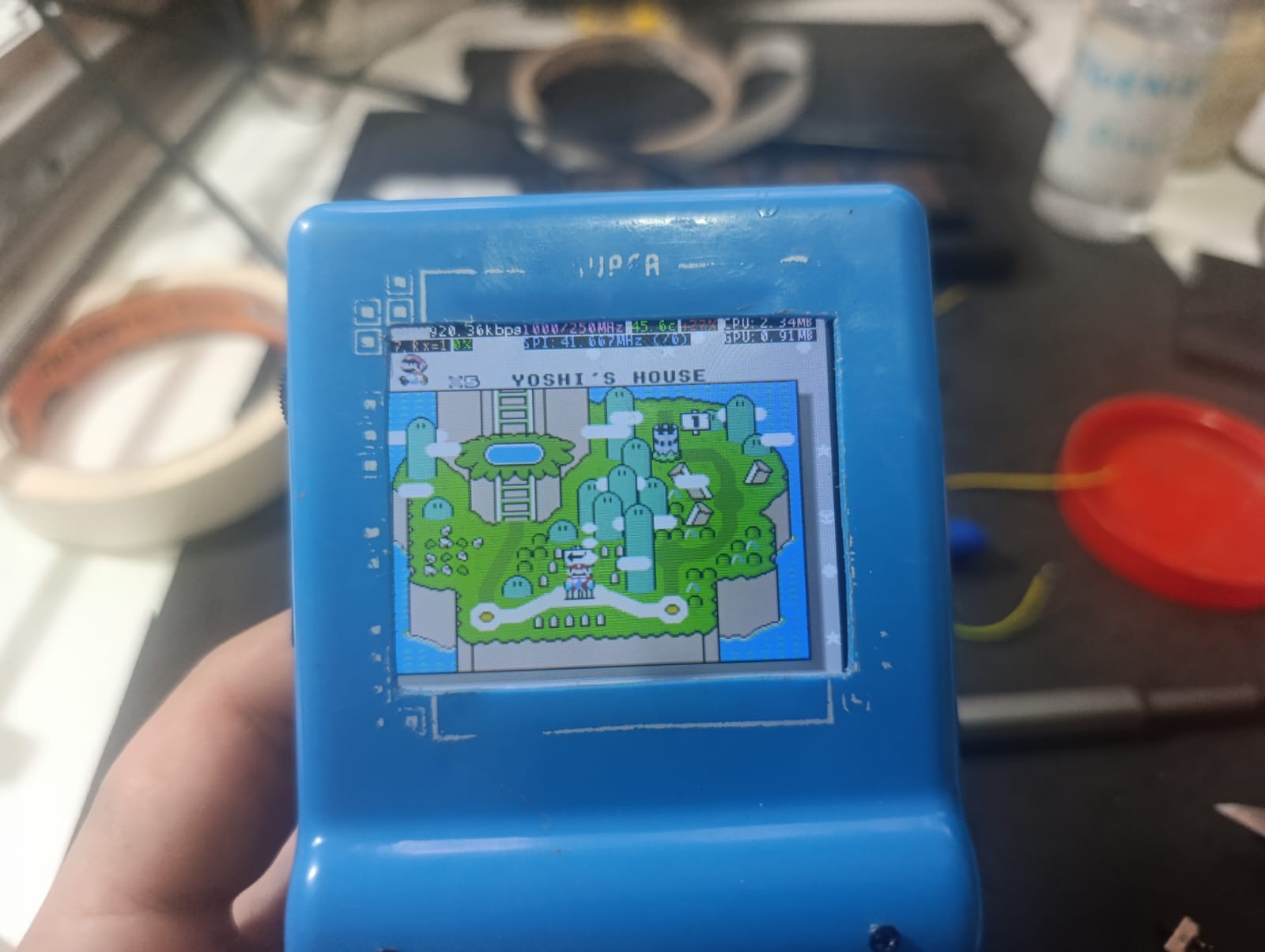
Ultimate Brick Game: A Childhood Icon Rewired
The infamous “9999-in-1” handheld was never real — so I rebuilt it with a Pi Zero, a 2.8 TFT display, and a 4800mAh battery
Become a Hackaday.io member
Already have an account? Log in.
Just one more thing
To make the experience fit your profile, pick a username and tell us what interests you.
Pick an awesome username
hackaday.io/
Your profile's URL: hackaday.io/username. Max 25 alphanumeric characters.
Pick a few interests
Projects that share your interests
People that share your interests


 bram
bram
 HybridAir
 repkid
thanks