Jorisclayton
-
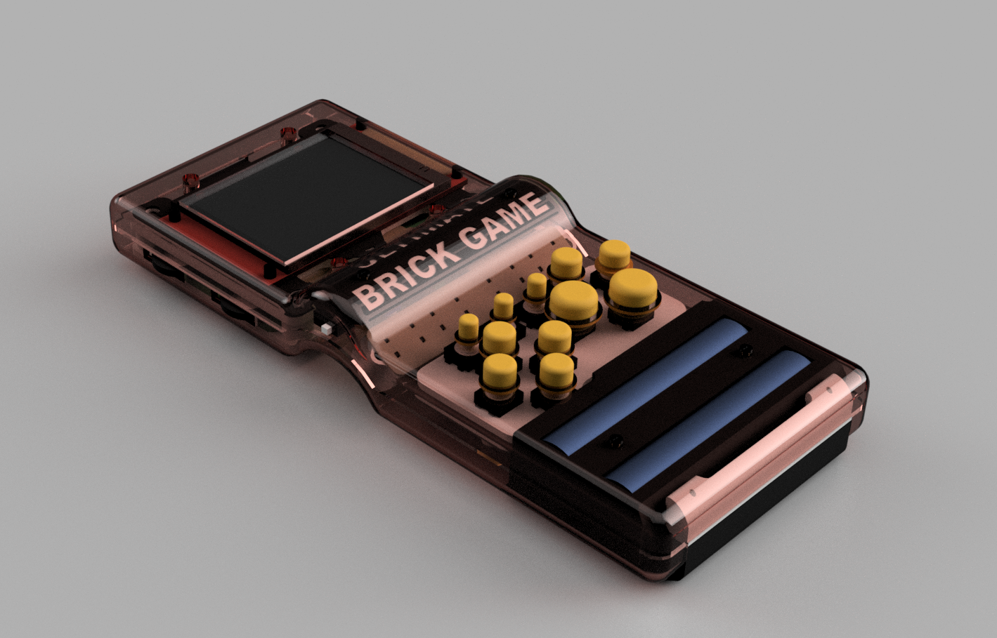
Version 4 - Professional PCBs and 2.8" Display
6 hours ago • 0 commentsThe journey from a "9999-in-1" toy to a high-performance handheld is almost complete. I am thrilled to announce Version 4, which I consider the definitive and final version of the Ultimate Brick Game.
Professional Engineering with PCBWay
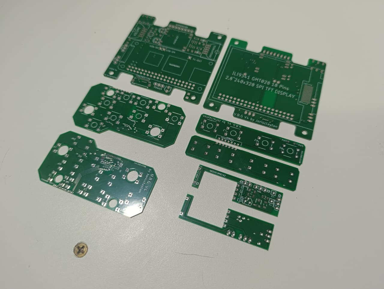
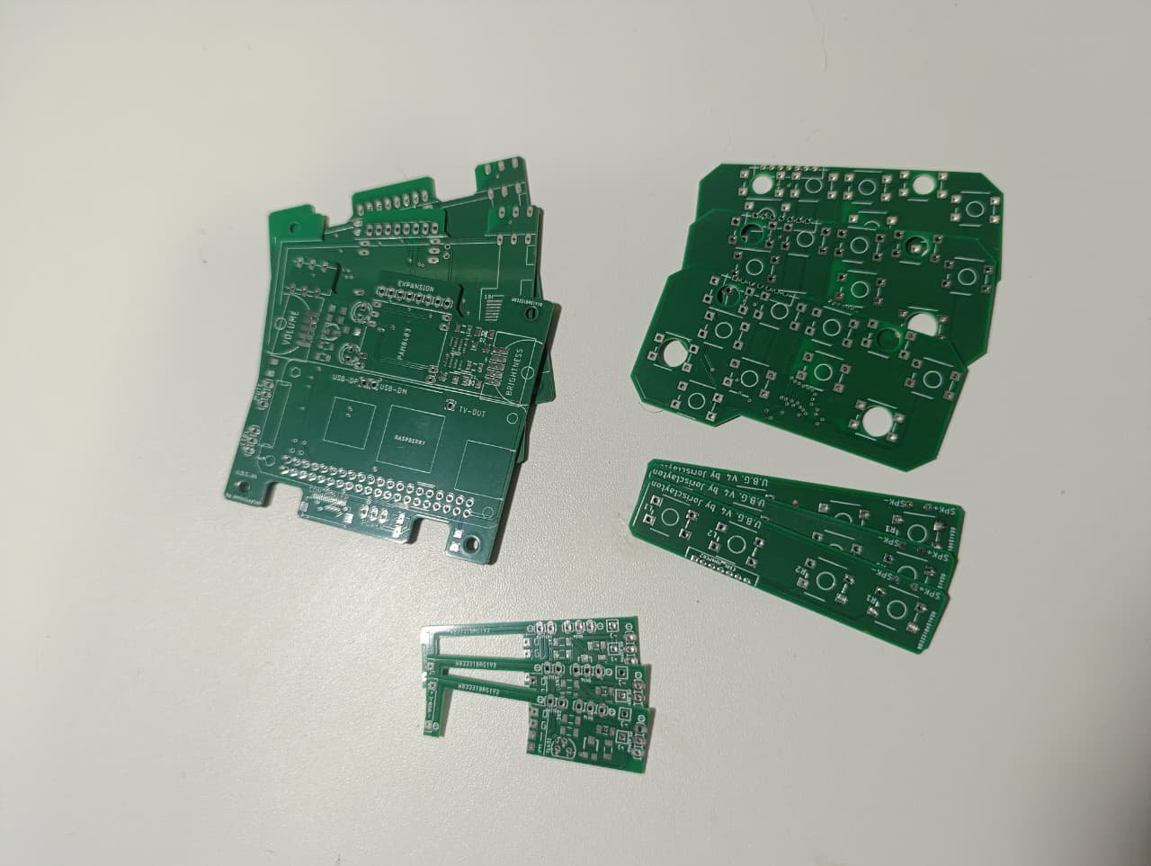
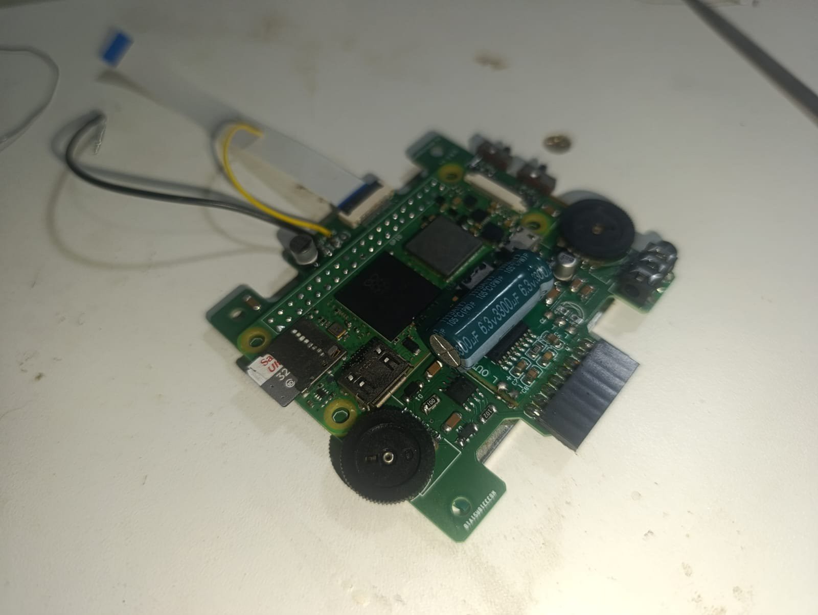
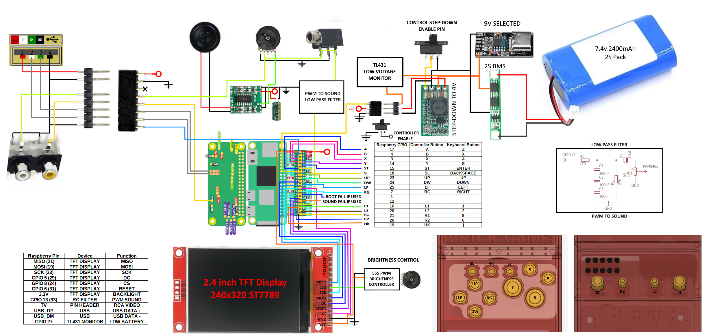
The biggest leap in this version was the transition to custom-designed PCBs. Thanks to the support and sponsorship of PCBWay, the internal hardware is now professional-grade. The boards came out perfect: extremely faithful to my schematics, with high-quality finishes and precise tolerances that allowed everything to fit like a glove inside the cramped original shell.
With these PCBs, the "birds' nest" of wires is gone. Assembly is now straightforward and replicable. I am making all Gerber files available so anyone can order their own boards and build this project.
Display and Performance
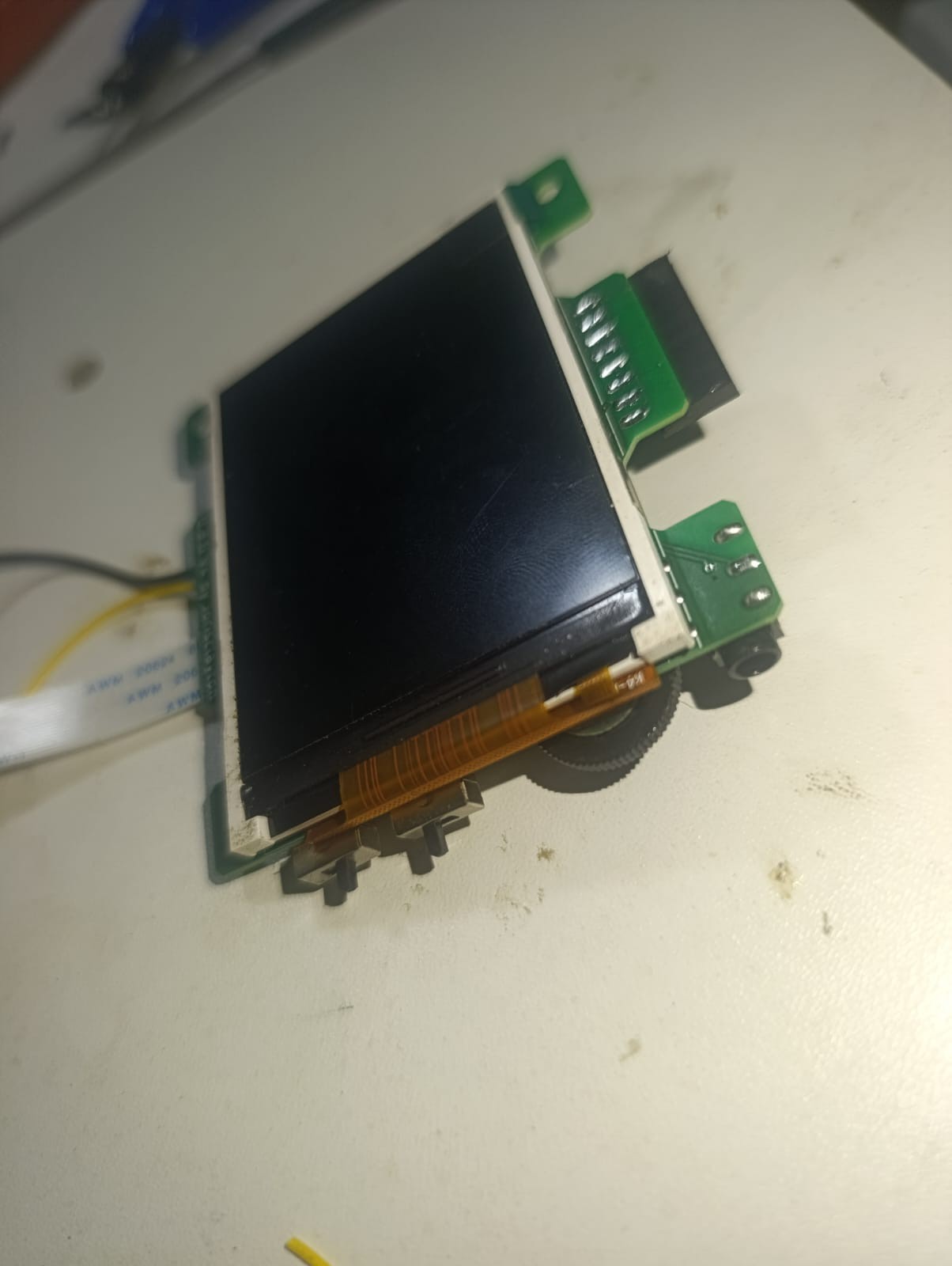
While this version was optimized for a 2.8-inch display, the design remains compatible with 2.4-inch screens.
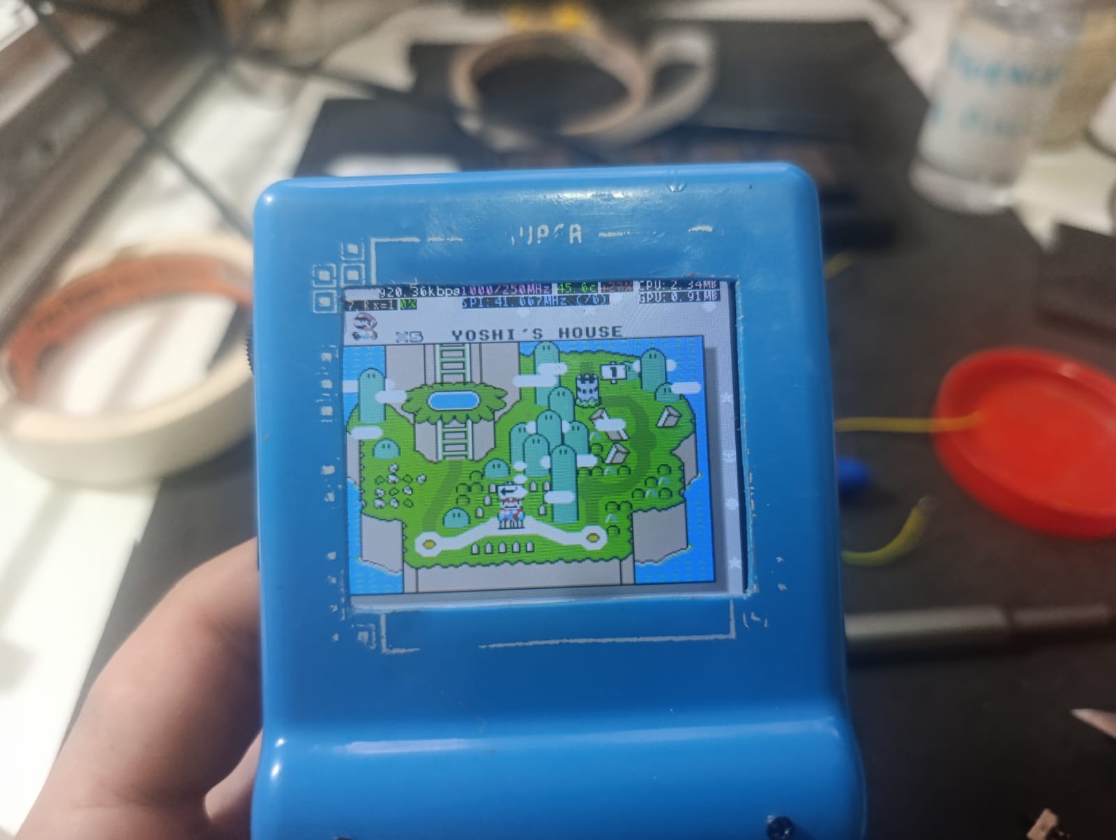
- Fluidity: The display runs at a solid 60 FPS thanks to driver optimizations.
- Audio: The sound is loud and clear, with a dedicated volume knob and a high-quality filter for the Pi's PWM output.
Power and Usability
The U.B.G. is now a reliable daily driver:
- Battery Life: Over 8 hours of continuous gameplay.
- Fast Charging: Full USB-C support. It handles 9V input, but I recommend using a BMS limited to 1.5A to ensure maximum compatibility with standard smartphone chargers.
- Pocket Mode: I’ve kept the dedicated switch to disable controller inputs. This allows you to keep the console powered on in your pocket without worrying about your character running into a pit while you're on the move.
What’s in the Files?
I am releasing the complete package for the community:
- Updated Gerbers: The most refined version of the boards, including all minor adjustments found during the V3-V4 transition.
- Configuration Backup: A "ready-to-go" set of files including the modified display drivers, startup routines, automated video-out switching logic, and pre-mapped controls.
- 3D Models & Templates: Final STLs for the internal supports and, most importantly, cutting templates (jigs) to help you modify the original Brick Game shell with precision.
Whats remaining: Expansion Board
The console is finished, but there is one optional "plus" in the works. The Expansion Board (for TV-out and external USB access) is already functional in its schematic form, allowing you to use the handheld as a desktop console. While it works, I’m still refining its physical form factor to make it look like a finished product.
Grab the files, order your PCBs at PCBWay, and let's keep the retro spirit alive!
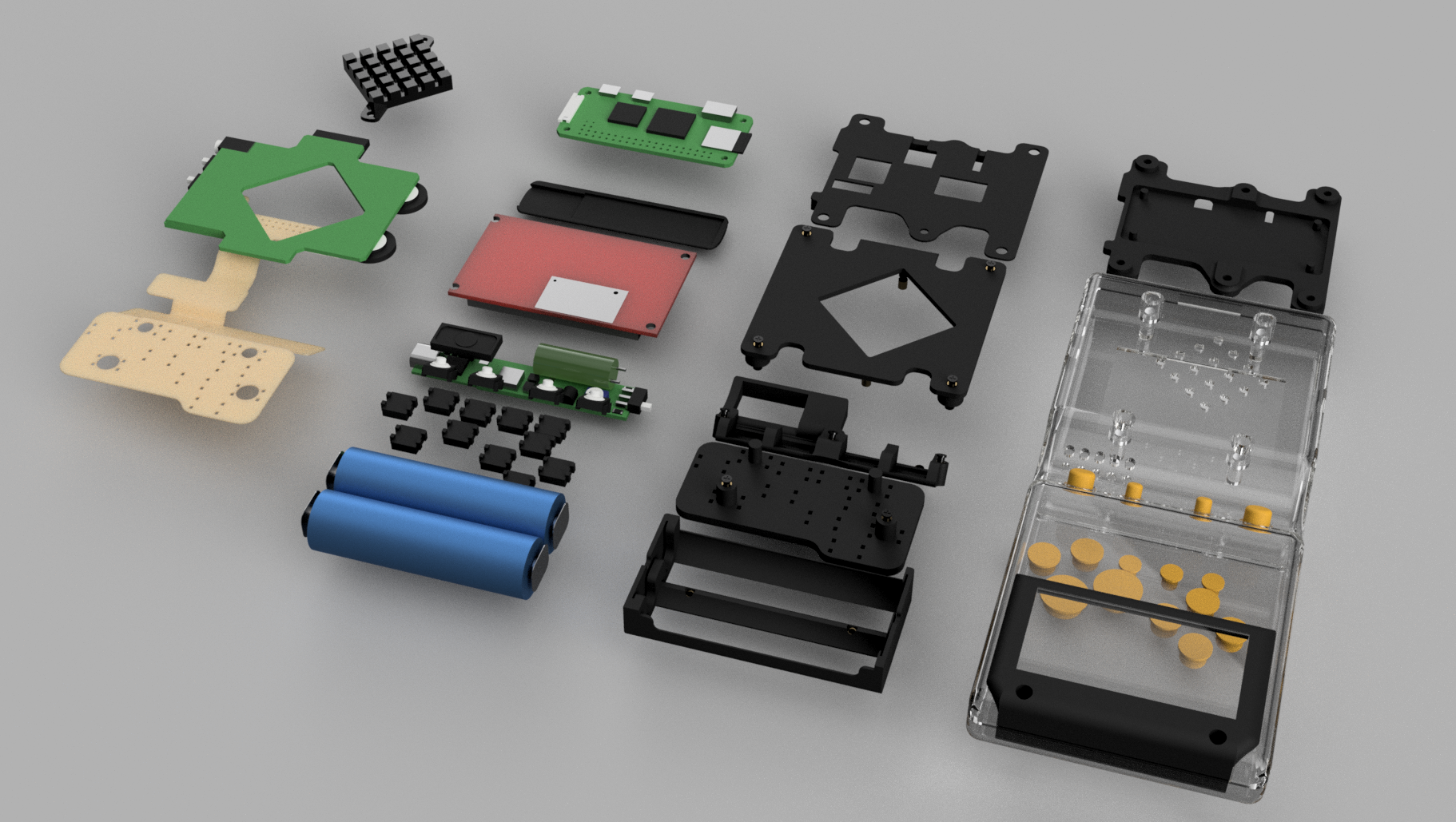
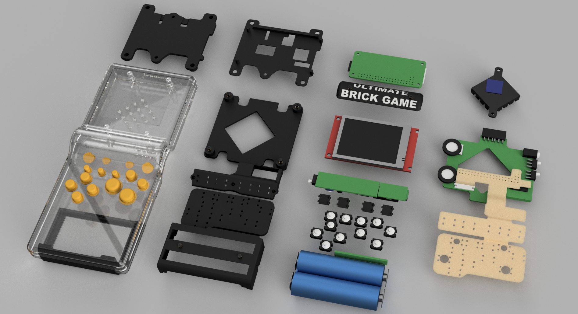
Photos and Assembly Overview
The photos below show the custom PCBs as manufactured, highlighting the excellent fabrication quality and how faithfully they match the original designs.
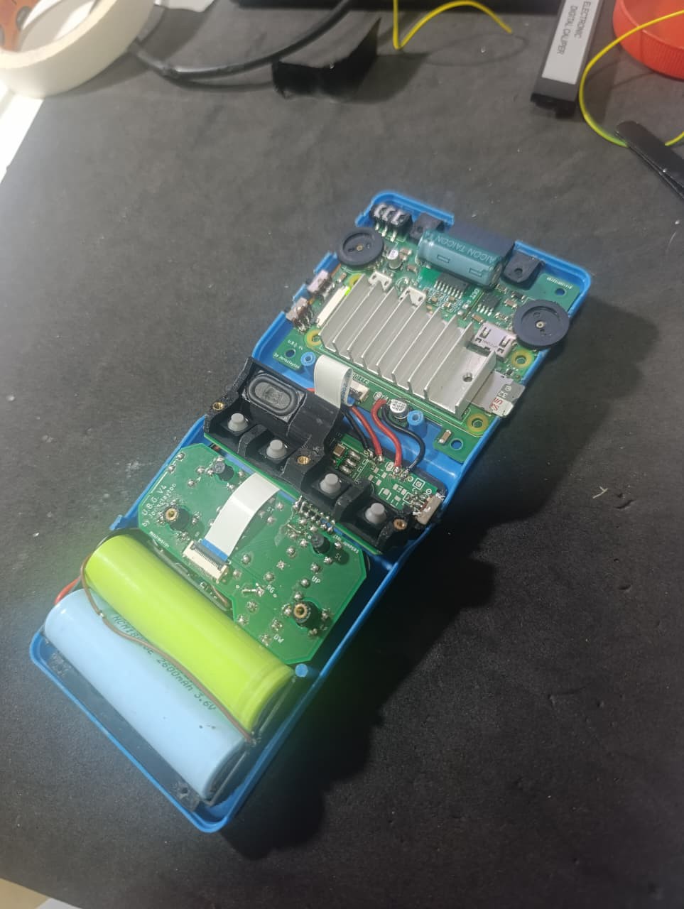
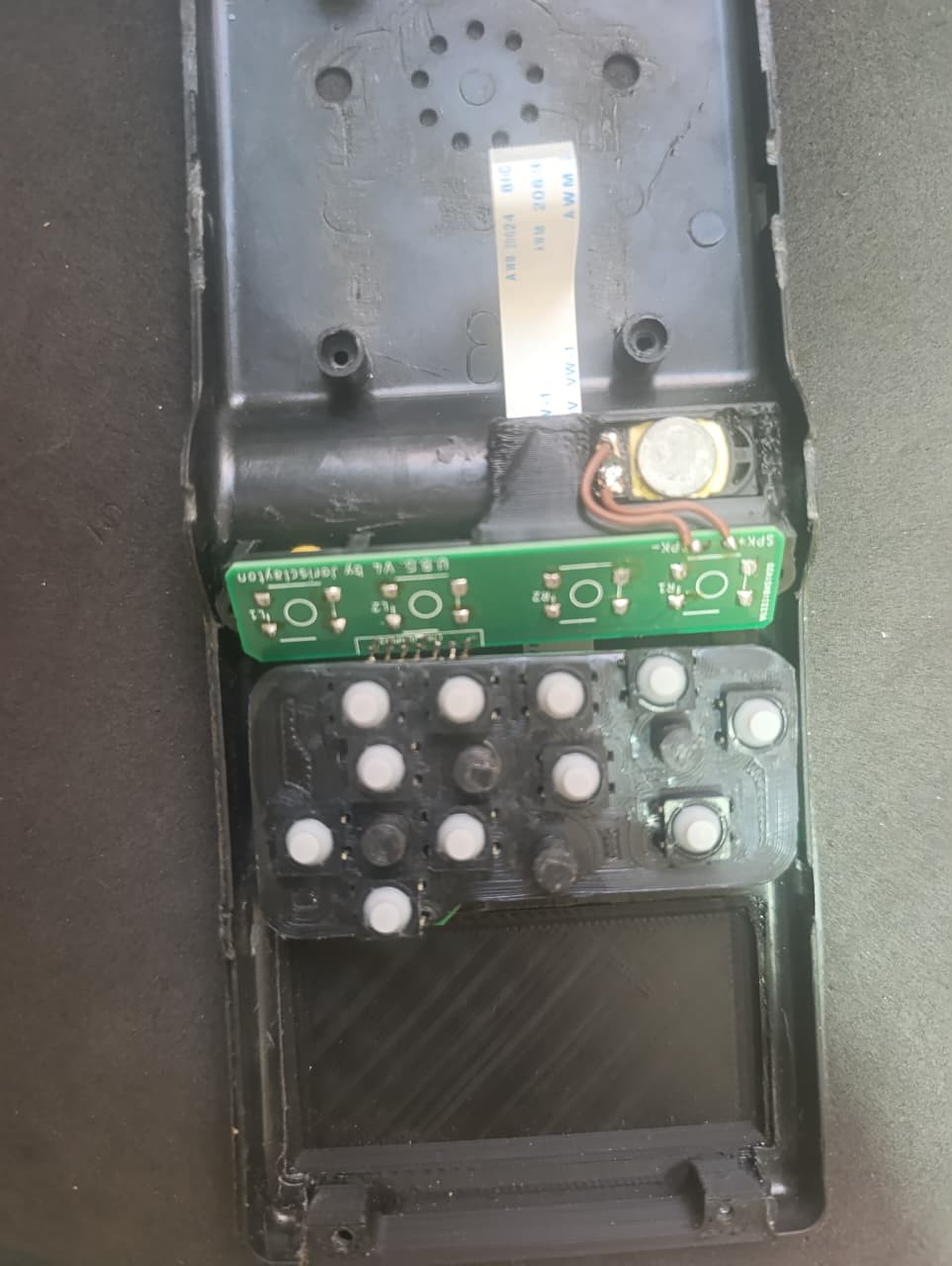
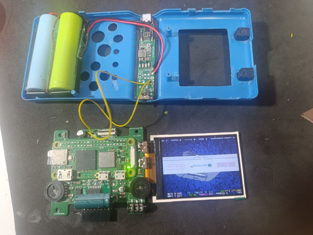
Following that, you can see the fully assembled console, demonstrating how the boards, wiring, and 3D-printed supports fit cleanly and precisely inside the original Brick Game shell.These images give a clear view of the final internal layout and the overall finish of the Version 4 build.
![]()
![]()
![]()
![]()
![]()
![]()
![]()
![]()
-
U.B.G V3 - Printed Circuit Boards
08/26/2025 at 01:05 • 0 commentsI have completed the schematic and layout of the three printed circuit boards (PCBs) for the project, and I am ready to proceed with their production. Before finalizing the design, I conducted a series of tests to ensure that the boards would actually fit inside the console. To do this, I printed the layouts on paper and cut them out to test how they would physically fit. This gave me the opportunity to modify the shape of the boards slightly to ensure they would fit perfectly in the available space inside the console.
The three boards have the following functions and features:
-
Main Board: This board will be responsible for several controls, including:
-
Volume control.
-
Audio generation using PWM (pulse-width modulation).
-
Display brightness control using a PWM circuit with an NE555 timer.
-
Headphone jack.
-
Mute switch for audio.
-
Switch to disable controller inputs (to allow the console to be stored in a pocket without unwanted inputs being triggered).
-
Expansion for additional connectors.
-
-
Power Board: This board will manage the console’s power and energy control. Its functions include:
-
Receiving power from the battery and the charger.
-
Regulating the voltage to 4.5 volts for the Raspberry Pi Zero.
-
Monitoring the battery level, using a TL431 to alert the user when the battery is nearly empty.
-
Power switch to control the enable pin of a step-down converter (97% efficiency tested with a bench load).
-
-
Flexible Board: This board will be responsible for connecting everything. Its functions include:
-
Connecting the controller buttons, speaker, USB pins, TV Out pins, and the TFT display to the Raspberry Pi’s GPIO pins.
-
Connecting the Main board to the Raspberry Pi by a 14 lines flexible connector.
-
Avoid the use of many wires, mostly from the controller buttons.
-
The expansion connector on the main board will include the USB data pins and the RCA output from the Raspberry Pi. This will allow for the connection of USB controllers or keyboards, USB flash drives, and other devices. Additionally, it will be possible to directly connect the console to a TV using the RCA output. These additions provide greater versatility and functionality to the console, expanding the options for interaction and connectivity.
These boards are a significant step toward completing the project, and I have already run several tests to ensure they function correctly before final production.
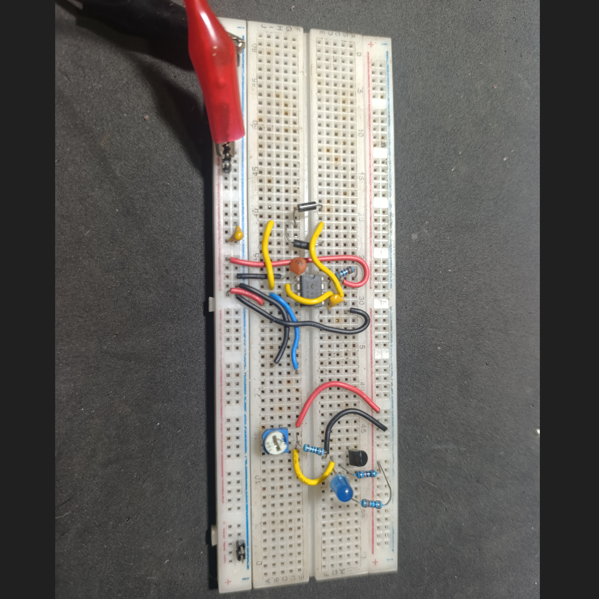
I also built some circuits on a breadboard to test the PWM generator with the 555 and the battery monitor with the TL431, and both worked well before I transferred them to the PCBs. The PWM brightness control will be adjusted with a rotary potentiometer, similar to the one used for the volume knob. The TL431 only needed a few resistors to work properly, but I also had to create a voltage divider on its output to adapt the levels. The TL431 was outputting 2V for "off" and 4.5V for "on," so I adjusted it to 1V for "off" and 2.5V for "on," making the signals compatible with the Raspberry Pi’s GPIO pins.
I’m attaching some photos showing the console with the new 3D-printed parts, along with the paper PCBs I made to test the fits and footprints. These images give a good look at how everything lines up and fits together before moving on to the final PCB production.
![]()
![]()
![]()
-
-
V2.5 Test Video Now on YouTube
08/03/2025 at 02:08 • 0 commentsI just uploaded a video showing the V2.5 version of the Ultimate Brick Game in action. This build was mainly used to test button layout, structural fit, and general usability before moving on to the final V3.
In the video, I run a few games to demonstrate performance and controls, including Donkey Kong Country 2 (SNES), The Legend of Zelda (NES – Second Quest), and Spyro: Year of the Dragon (PS1).
Check it out here:
https://youtu.be/qvZEKYZuL_0Feedback and suggestions are always welcome!
-
Version 3.0 Designed – Schematics and 3D Models
08/03/2025 at 01:44 • 0 commentsI'm ready with the V3 design. The 3D models are fine; I’ve already printed and tested them, and they fit properly. I created a complete 3D model of the whole console to help, since the components are getting very close to each other and the available space is disappearing quickly. I'm currently working with a version that I like to call V2.5, as it was made to test the button positions and the internal structures for the V3. The new controller layout works much better than in V1 and helped me identify the problems I needed to solve to design this new version.
The software side will change just slightly, as V3 will include a Low Battery Warning to help save the game before a sudden shutdown. Some electronic components also need to be modified. The Raspberry Pi works fine when connected directly to a 3.7V source (operating between 4.2V and 3.2V), but the BMS cuts off the battery when it reaches around 2.6V — which seems to be normal behavior. However, this causes the system to crash before it powers down cleanly, so the handheld can be turned on again only to crash repeatedly.
V3 will also feature a display brightness control, implemented through a rotary potentiometer similar to the one used for volume. Currently, in V2.5, the potentiometer is wired directly to adjust the TFT’s supply voltage — and while it works, it doesn’t provide perfect control. In the new version, I plan to build a PWM-based dimming circuit using an SMD 555 timer, which will offer smoother and more stable brightness adjustment.
Additionally, V3 will include three On/Off switches with different functions: one to mute the audio, one to disable the controls (useful when storing the handheld while keeping it powered on, preventing unwanted input), and a third switch simply to power the system on and off.
I came up with a solution to monitor the voltage, but distinguishing 3.2V from 2.8V is difficult due to how close those values are. I also couldn’t find a MOSFET that works well in that range, and a simple TL431 circuit wouldn’t function properly at these voltages. So I decided to switch to a 2S 2400mAh battery setup. With that, I’ll use a very compact and approximately 97% efficient step-down converter (I tested it with an electronic load and it performed really well). This circuit includes an enable pin, which will serve the same purpose as the MOSFET I used before, eliminating one component.
For the battery monitor, I’ll build a small circuit using a TL431 and some resistors, which will pull a GPIO pin LOW when the battery level drops below 6.4V, indicating that the battery is nearly empty. The TFT display will then show a warning for the user, and the driver I’m using can handle this input.
The 3D models will now be updated to fit a PCB. Yes, I’m considering using a printed circuit board to connect the electronic parts to the Raspberry Pi and the controller. I’ll use three PCBs: one of them will be a flexible board that connects the buttons to the main board via a flex connector and connects to the Raspberry Pi through solder points on the GPIO.
I'm not yet done with the final electronic design, but I’ll work on that as soon as possible and try to build one. Currently, the V2.5 uses a lot of wiring (much thinner than what I showed in previous pictures), and it’s a bit complicated to assemble and troubleshoot — sometimes I need to desolder parts just to open things up, and it’s a mess.
I’m already enjoying the console. I’ve played NES and SNES Zeldas, PS1 Spyro, and all the SNES Donkey Kong Country games — they all run great and the controllers fit well. For N64, I’m still having trouble configuring the controllers properly, but they work okay, and I’ve already played some Mario Kart 64 races. I’m having a lot of fun building this project.
If anyone wants to build one of these, I’ll be happy to help as much as I can, but please wait until the V3 is finished, because I still need to fix some things and I’m sure new problems will appear once the final version is alive.
Below are some images of the new 3D models. I uploaded them to Thingiverse, along with the new (unfinished) schematic that will be used in V3. I plan to make a proper version in Eagle or EasyEDA in the future and use it to manufacture the PCBs. But first I need to run more tests and create some custom libraries for the components I plan to use.
3D files are available here: https://www.thingiverse.com/thing:7107931. They include parts to assemble the console and templates to modify the original Brick Game shell.
I’m open to suggestions — feel free to share any ideas or feedback.
![]()
![]()
![]()
![]()
-
Linux Configuration Files and Drivers
07/27/2025 at 21:58 • 0 commentsAs the project has progressed, I now feel comfortable sharing the configuration files and drivers required to make everything work. These include files necessary for Linux to properly output to the TFT display, recognize controllers, and send audio through a GPIO pin.
The Raspberry Pi also needs to detect whether the RCA board is connected, so it can automatically choose between HDMI (TFT) or Composite Video Output. This is managed by swapping configuration files during boot based on GPIO states. I’ll describe all the parts below, and I’ve also created a "Backup" file containing the compiled driver for my specific display and the necessary scripts, already placed into the correct folders for plug-and-play use.
In the future, I plan to add a feature to notify the user when the battery is low. The TFT driver already supports this — I just need a GPIO to be pulled LOW when the voltage drops below a threshold. I believe a TL431 could handle this by monitoring the battery voltage.
Remember: this is an ongoing project. Some things have already changed from the first version of the U.B.G., and the current files work with the second prototype I'm testing. I'm confident they’ll work on the older version too — only a few controller pin mappings have changed, which I’ll update ASAP.All the files described below will be available for download, along with a
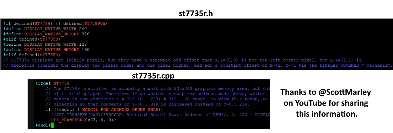
how_to_do.txtfile that explains what needs to be executed for everything to work properly.- FBCP-ili9341 Driver: This one is responsible for controlling the TFT display and giving us a good refresh rate, as it works with the SPI protocol with very fast bus rates, close to 50 MHz. The display can act as an HDMI device and worked great for this project. Some parameters need to be configured when compiling the driver, all of them are better described in the driver's main page on Github (https://github.com/juj/fbcp-ili9341), but, if you are using the 320x240 ST7789 display, there are some changes needed to be made for the driver files to fit this specific one. As the ILI9341 doesn't default have this display I edited the st7735r.h and st7735r.cpp modifying the resolution and part of the SPI protocol communication as the images below. With this made, the driver has been compiled with some specific parameters to work well with this one command "cmake -DST7789=ON -DGPIO_TFT_DATA_CONTROL=5 -DGPIO_TFT_RESET_PIN=6 -DSPI_BUS_CLOCK_DIVISOR=6 -DDISPLAY_ROTATE_180_DEGREES=ON -DDISPLAY_INVERT_COLORS=ON -DSTATISTICS=0 .." (DSTATISTICS=0 must be used only if you don't want the FPS, bus speed, bus frequency and etc to be shown, it's really useful for troubleshooting process) and the command "sudo /home/pi/fbcp-ili9341/build/fbcp-ili9341 &" needs to be added to /etc/rc.local file.
It’s important to note that this driver makes use of a partial refresh on the display screen, modifying only the parts that changed between frames and it uses some of the CPU. If your display can handle bigger SPI bus frequencies and accept a really good refresh rate, you can save some CPU by modifying some parts of the config.h file before compiling. I'm using "#define UPDATE_FRAMES_IN_SINGLE_RECTANGULAR_DIFF", this saved me a lot of CPU, turning able to run N64 games much better than before this change. Also, the ILI9341 driver page has a topic describing all the methods to get that CPU saving features. - Config.txt file - swap video modes: As the Raspberry Pi Zero cannot handle HDMI and Composite videos at the same time and I want the console to be able to display on a TV or monitor just by plugging it in, I made a simple script that monitors a GPIO pin to know if the console is running on handheld format or if it's plugged into the RCA cable adapter, so it checks at every boot or shutdown the state of the Brick Game and swaps between two config.txt files. Basically, it copies the content of a config.tft or a config.rca to the config.txt file; if it differs from the actual video output configuration, the script reboots the system now with the correct monitor selected. The scripts are "select-video.sh" and "select-video-shutdown.sh" on /boot directory, they will be executed by "video-switch-shutdown.service" on /etc/systemd/system or by this command "sudo /boot/select-video.sh &" added on /etc/rc.local file. The configurations for each device are simple: for the TFT, the "dtoverlay=fbcp-ili9341" command together with some HDMI configurations need to be done; for the RCA, it's just enable TVout and set the sdtv mode to 2.
- Config.txt file - controller configuration: Also on the boot.txt (understand this as the .rca and .tft files that need to be modified) the controller buttons and equivalent keyboard keys are defined, all of this is done by some commands like this one for the Start button to act as ENTER on GPIO 15: "dtoverlay=gpio-key,gpio=15,active_low=1,gpio_pull=up,label=START,keycode=28 #ST = ENTER". That's important to know, there are some GPIOs that will not work or get conflict with something. In my tests, the GPIOs 1 and 12 need to be skipped, as they make the system not work or disable the audio.
- Config.txt file - audio configuration: As the Raspberry Pi Zero does not have the default analog audio output and I don't want to use any digital audio boards, I came up with just using a PWM pin to generate a sound-like signal that needs to be sent to an RC filter to get the proper audio output. It is done simply by putting these commands in the config.txt files: "dtparam=audio=on", "gpio=13=a0", "dtoverlay=audremap", "enable_jack=on". With this, the GPIO 13 is now a mono audio output via PWM signal.
- SplashScreen modify: It's just adding my own image (thanks to ChatGPT) to the RetroPie directory \RetroPie\splashscreens and configuring it to be used instead of the default one using the RetroPie config program.
- Theme: I chose a theme called something "like TFT" (I just searched for TFT in the theme install program) that makes it easier to see the ROM names when scrolling. It looks better than the default RetroPie theme on a small display like the one I'm using.
![]()
![]()
- FBCP-ili9341 Driver: This one is responsible for controlling the TFT display and giving us a good refresh rate, as it works with the SPI protocol with very fast bus rates, close to 50 MHz. The display can act as an HDMI device and worked great for this project. Some parameters need to be configured when compiling the driver, all of them are better described in the driver's main page on Github (https://github.com/juj/fbcp-ili9341), but, if you are using the 320x240 ST7789 display, there are some changes needed to be made for the driver files to fit this specific one. As the ILI9341 doesn't default have this display I edited the st7735r.h and st7735r.cpp modifying the resolution and part of the SPI protocol communication as the images below. With this made, the driver has been compiled with some specific parameters to work well with this one command "cmake -DST7789=ON -DGPIO_TFT_DATA_CONTROL=5 -DGPIO_TFT_RESET_PIN=6 -DSPI_BUS_CLOCK_DIVISOR=6 -DDISPLAY_ROTATE_180_DEGREES=ON -DDISPLAY_INVERT_COLORS=ON -DSTATISTICS=0 .." (DSTATISTICS=0 must be used only if you don't want the FPS, bus speed, bus frequency and etc to be shown, it's really useful for troubleshooting process) and the command "sudo /home/pi/fbcp-ili9341/build/fbcp-ili9341 &" needs to be added to /etc/rc.local file.
-
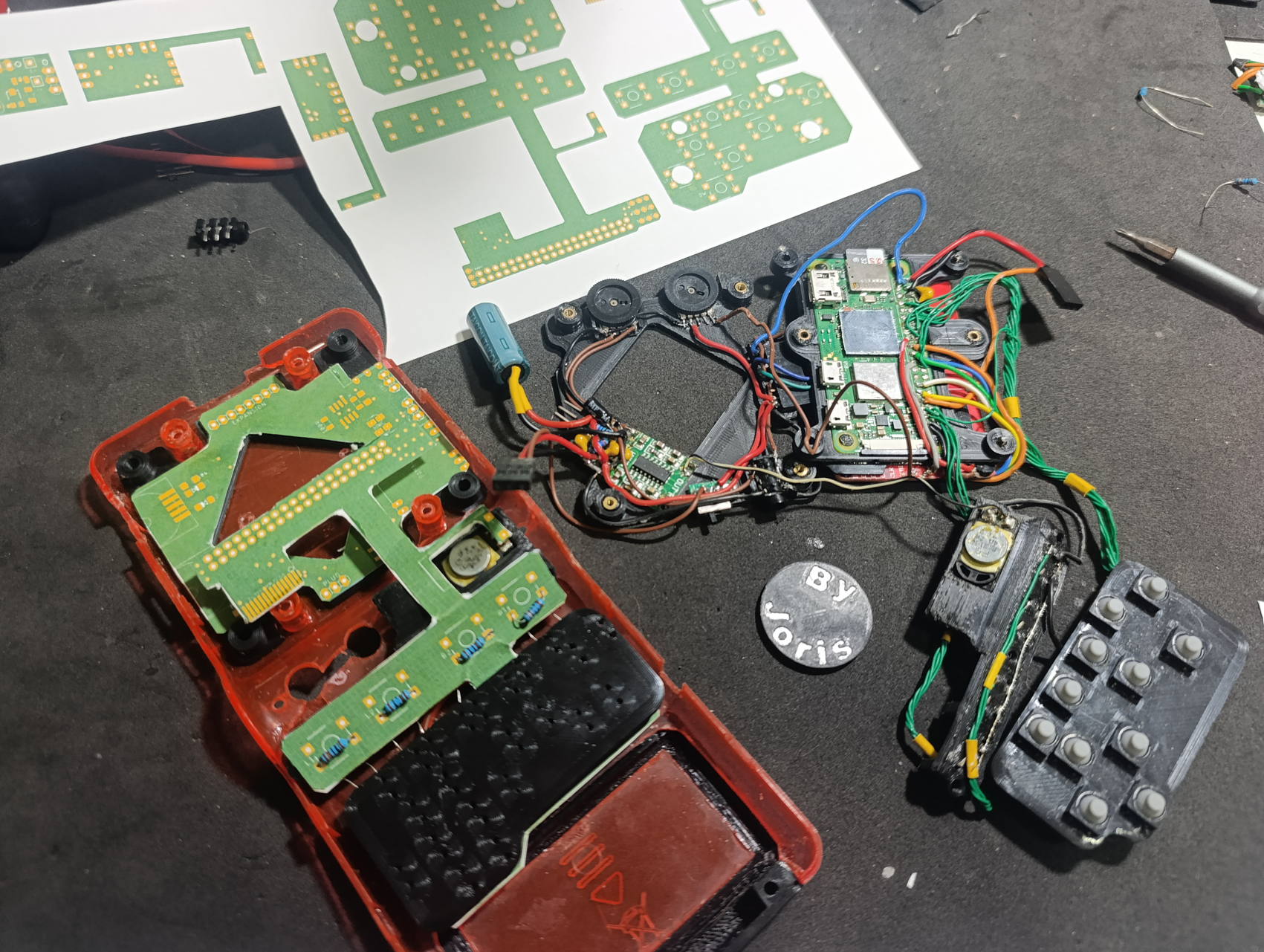
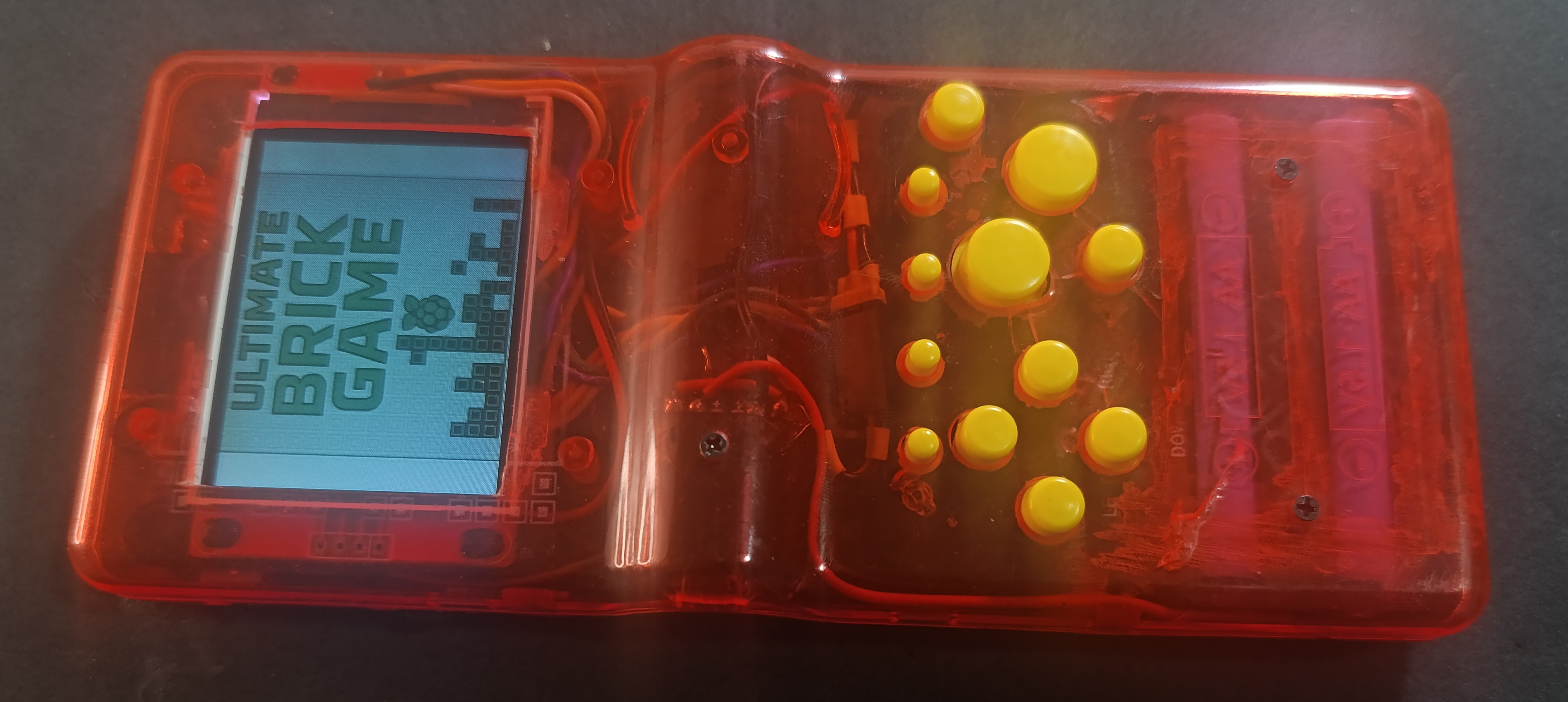
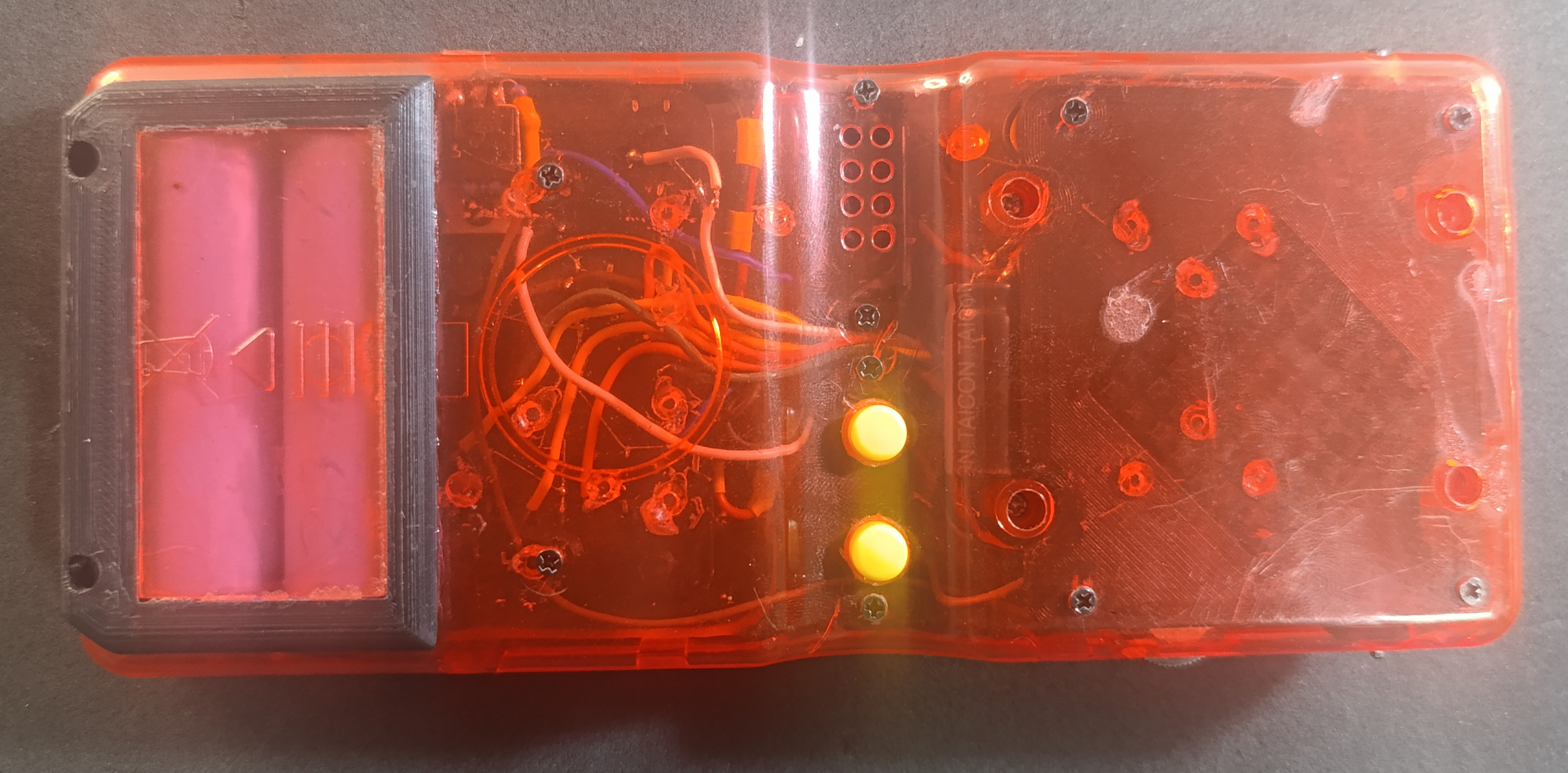
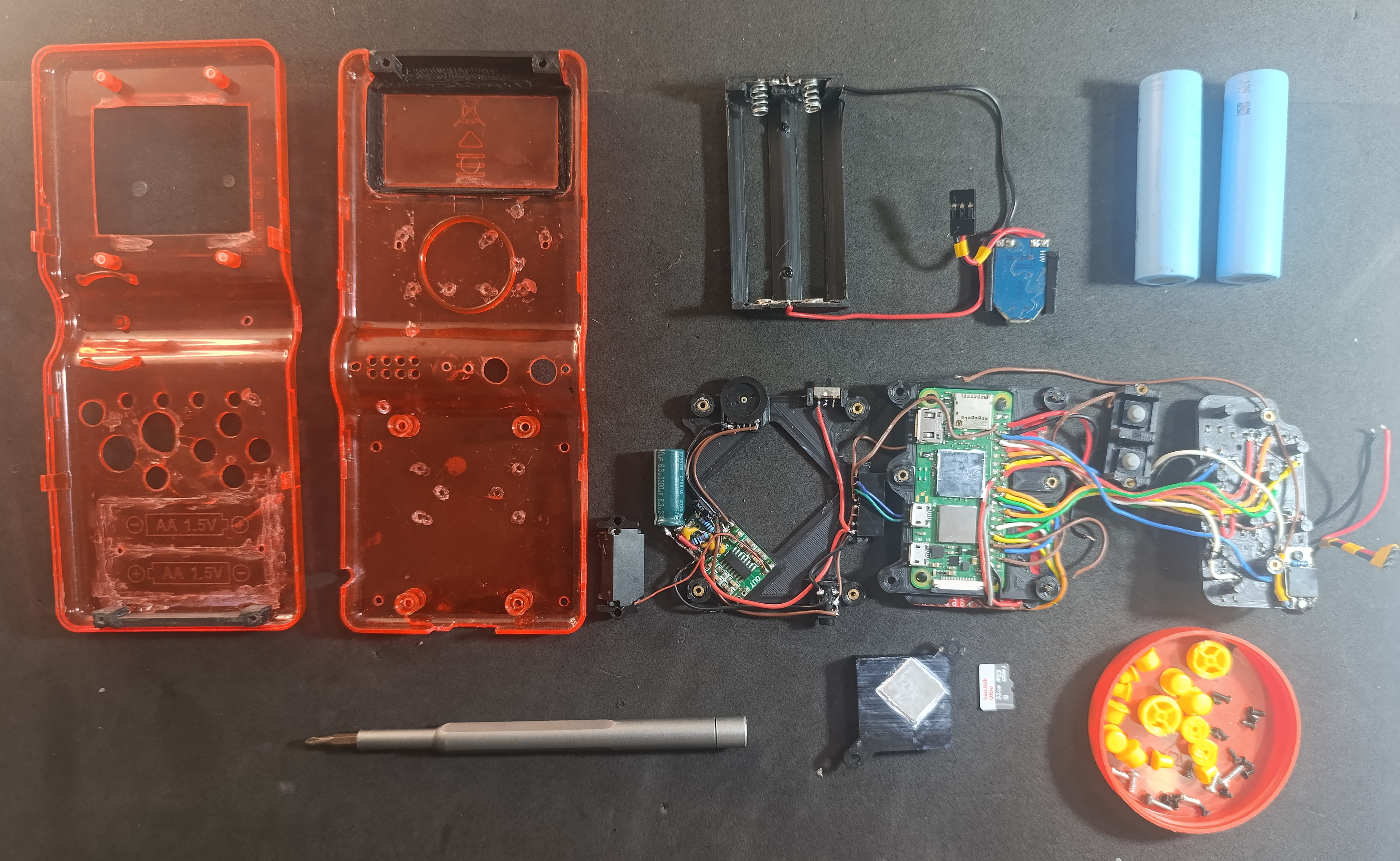
All Parts Together - Wiring Finished and Now workin!
07/06/2025 at 19:46 • 0 commentsThis is my first working version of the console. I'm using it to figure out what should stay and what needs improvement in the final build — but it's already fully functional. I added a 50x50mm aluminum heatsink, and noticed that I’ll need a 0.5mm thermal pad to get good contact with the CPU. I also tried adding a 6300 µF capacitor on the main power line, but turns out it’s not really necessary — the audio was fine without it. On the other hand, I had some issues with the headphone jack connection and I’ll need to redesign that part.
The internal layout uses custom 3D-printed parts. All electronics are mounted on those pieces, held in place with M2 machine screws. The screen and the Raspberry Pi Zero W are fixed together in a single printed frame, which is then attached to a second frame that holds the audio amp (PAM8403), power button, RC filter, volume knob, and 3.5mm audio jack. All buttons — both front and rear — are also mounted on dedicated printed structures.
The 18650 cells are held by springs, which makes them easy to replace. If I had access to a spot welder, I’d probably go with nickel strip and fixed terminals instead. The only parts glued to the shell are the ones that physically change the case — mainly the section I had to expand to fit the dual 18650s. I still managed to reuse the original battery cover, which gives a nice translucent look to the cells.
It was a tight fit. I used wires that were way too thick, which made assembly harder than it needed to be. For the next version, I’ll use thinner, more flexible wires. I also had to trim the TFT display edges to make it fit the front shell, which made the cable connection a bit tricky — but it works fine.
On the software side, I made a few changes that I’ll explain in detail later. I used specific drivers for the SPI display, configured GPIOs for both audio (PWM) and button input, and implemented two different
config.txtfiles at boot — one for handheld mode (with the TFT screen) and another for RCA output when connected to a TV. I have to reboot to switch modes because the current driver setup can’t handle both at once. The charging port is still micro USB, but I’ll probably switch to USB-C next time.Rear buttons are not mapped yet, but in the next revision I plan to include full L1/L2/R1/R2 support with better positioning. The original speaker was terrible — I replaced it with a smaller but stronger one that sounds much better.
The console uses very little power. With a light overclock to 1200 MHz, it still runs for over 8 hours on a full charge with two 18650s, and doesn’t overheat. The passive 50x50mm heatsink is enough — I won’t use an active fan anymore. The RCA+USB video output module is working fine. When I plug it in and reboot, it disables the TFT and enables RCA automatically, since I can’t run both displays simultaneously with the current configuration.
![]()
![]()
![]()
-
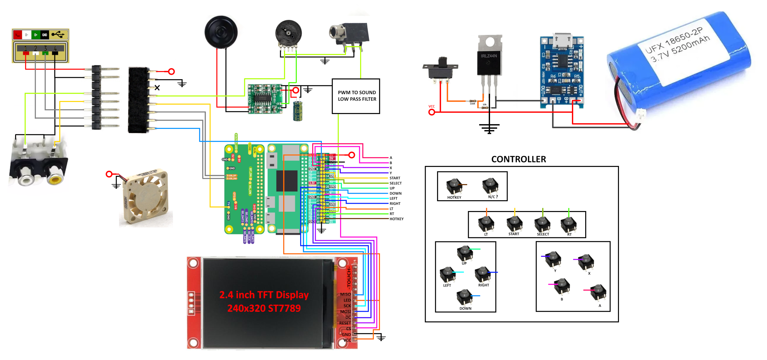
Ultimate Brick Schematic
07/05/2025 at 01:47 • 0 commentsI already made a simple, easy-to-follow schematic. Its the version one and shows all the parts, including the Raspberry Pi, TFT display, sound, buttons, power, and battery components. Since I’m working with thin wires, it’s more than enough to follow and connect everything. I’m now testing the parts — the Raspberry Pi Zero arrived, and I’ve started wiring everything. As soon as possible, I’ll update the project with a working version of the console.
![]()
Ultimate Brick Game: A Childhood Icon Rewired
The infamous “9999-in-1” handheld was never real — so I rebuilt it with a Pi Zero, a 2.8 TFT display, and a 4800mAh battery