-
Epilog
08/19/2025 at 14:52 • 0 commentsLast hour of the contest, time to recap.
Well it works ... kinda. Adding many "im scared potentiometers" really wasnt the brightest of my ideas. Also the lack of testpoints made things just harder.
Remember kids: TEST POINTS ! LOTS AND LOTS OF TESTPOINTS !
-
After much much tweaking i got it to self adjust over a long ~2min period of time. Using 1-Meg pots was stupid. Once you got one parameter sorta right just a little mistake and the values are all over again. It worked once, but replicating it again for documentation, would take too long. The pots and lack of points made it hell to debug. Deadline is approaching.
The screenshots from the last log must be enough.
-
Well it was a fun experience, learned a thing or two about opamps, control loops and PLL´s so it was worth it.
I will stop the project here because it was solely for the contest and has no real use while being a crazy timesink.
If i would redo it sometime i would directly use a NE555 squarewave and apply the shaping.
See you on the next contest.
-
results results RESUUUUULTS
08/18/2025 at 12:00 • 0 commentsSo first assmebly ... power on and ..... nothing.
The first two hours were just spent with debugging .... or more precisely: finding the few spots where i screwed up soldering.
After that i spent another hour just tweaking around with the values .... but in the end it paid off:
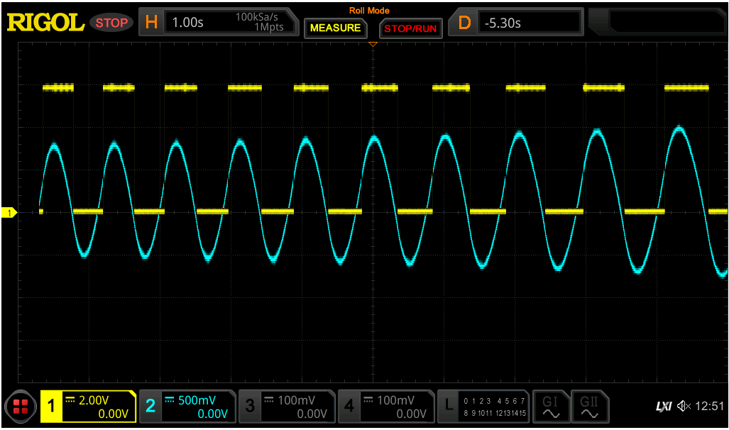
![]()
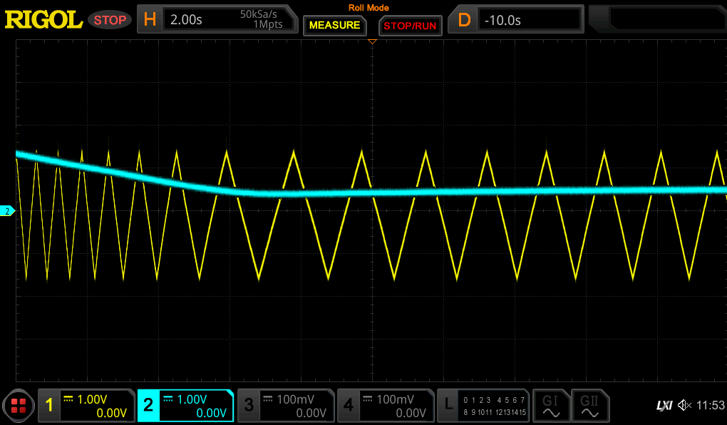
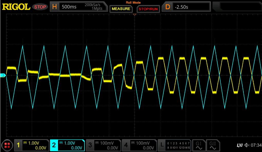
What you can see here in blue is the output of the final stage, eg. the sine output.
You can kinda see how the frequency slowly gets lower towards the wanted 1Hz given from the 555 timer.
Also the wave itself looks pretty enough for me. Not too much skewed. Im just a bit unhappy with the offset.
Tomorrow is the last day of the contest, hopefully i get to tweak the values a bit more to get towards my wanted frequency.
-
Print assembly
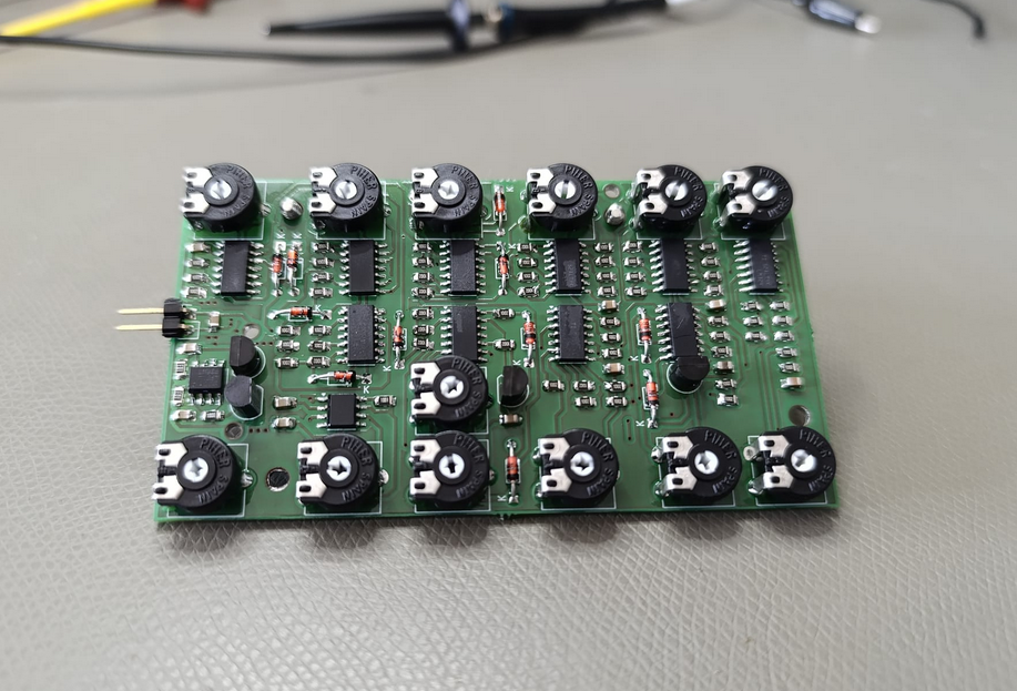
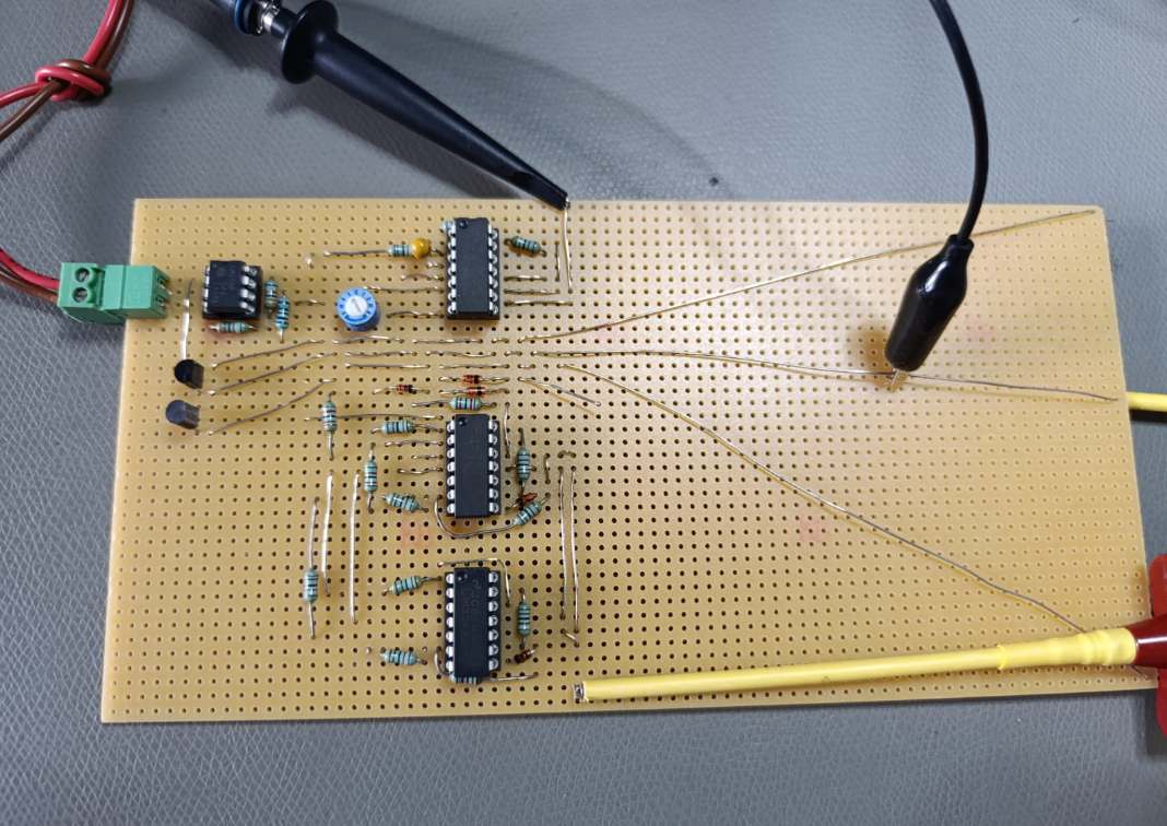
08/18/2025 at 11:53 • 0 commentsSo the PCB and components finally arrived, time to undust my smd soldering skills:
![]()
! WHAT A BEAUTY !
-
Prototyping!
07/18/2025 at 10:05 • 0 commentsThe concept works.
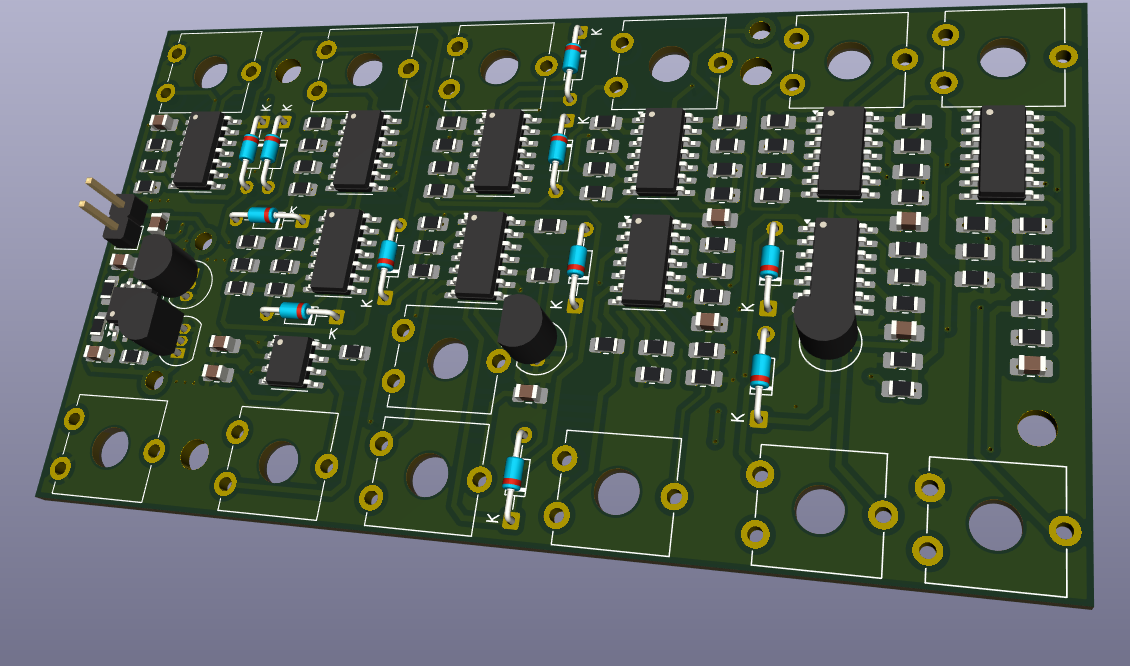
So its now time for a print to make it pretty.
![]()
I made the first one using the THT parts from the breadboard. Turned out it was waaay too big and thus expensive.
Opted for SMD parts instead slashing the size down to 1/3 and halving the cost to manufacture.
I also added many potentiometers ... i dont trust the simulation and calculation THAT much ....
Now we wait ...
-
Closing the loop
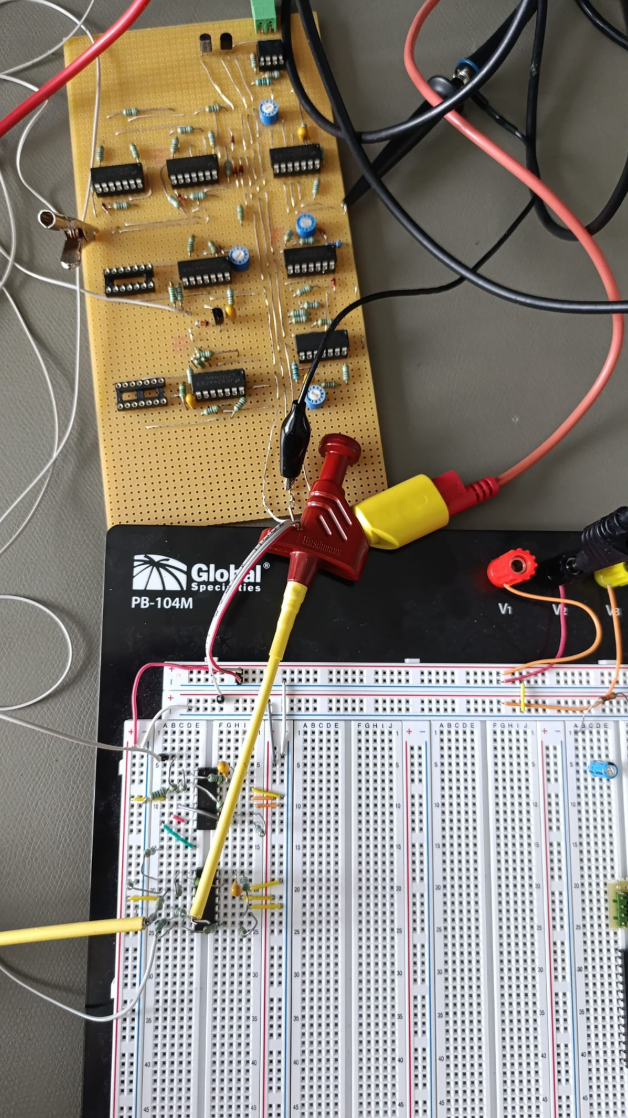
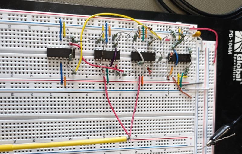
07/15/2025 at 11:07 • 0 commentsI went out of space on my perfboard .... and blew my opamp power supply twice .... and broke a thing or two ... maybe even twice.
So i continued like this:
![]()
Building the reference frequency from my oscilloscope and closing the loop.
![]()
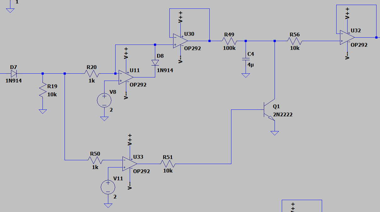
I subtract the voltage from the oscillator from the reference and get an error.
Another integrator and i added an offset so it wont get stuck on startup.
The result then gets fed into the main oscillator as a set voltage.
And .....
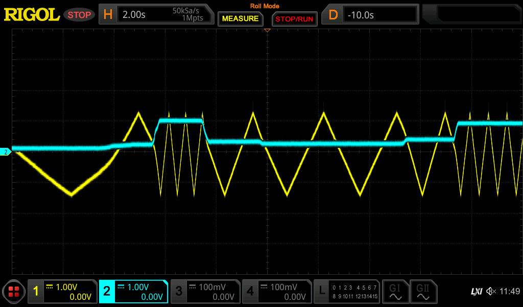
![]()
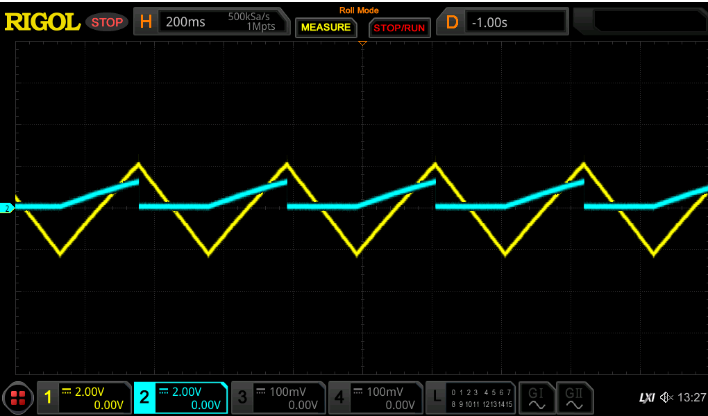
IT ACTUALLY WORKS I CANT BELIEVE IT.
Yellow = Triangle from oscillator
Blue = Control voltage to oscillator
After a few seconds the output actually settles to the given reference frequency i cant believe it.
Is it accurate tho? well ... no, not yet .... but we will get to that....
-
The frequency counter
07/15/2025 at 10:59 • 0 commentsTo be able to compare two frequencies we first need to convert a frequency to a voltage.
One might just use an RC filter .... but at 1Hz thats not feasable.
So i came up with a different approach.
![]()
I take the positive part of the squarewave output, and charge a capacitor. On the negative half i discharge it.
Higher frequency = less time to charge = lower voltage
Lower frequency = more time to charge = higher voltage
Easy, right?
![]()
On the output we get this.
Now we average this output with another I-controller integrator.
![]()
No we do the same thing with our reference frequency
-
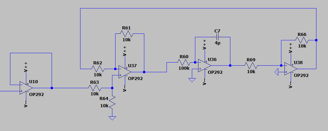
Sinewave shaping
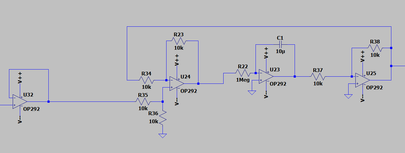
07/11/2025 at 07:19 • 0 commentsSo to give the sinewave the final touch, i use an integrator to generate a sine wave.
However, using only an integrator will make the output run away since the slightest offset will also get integrated over time.
The solution: a PID controller..... well ... just an I-Controller
![]()
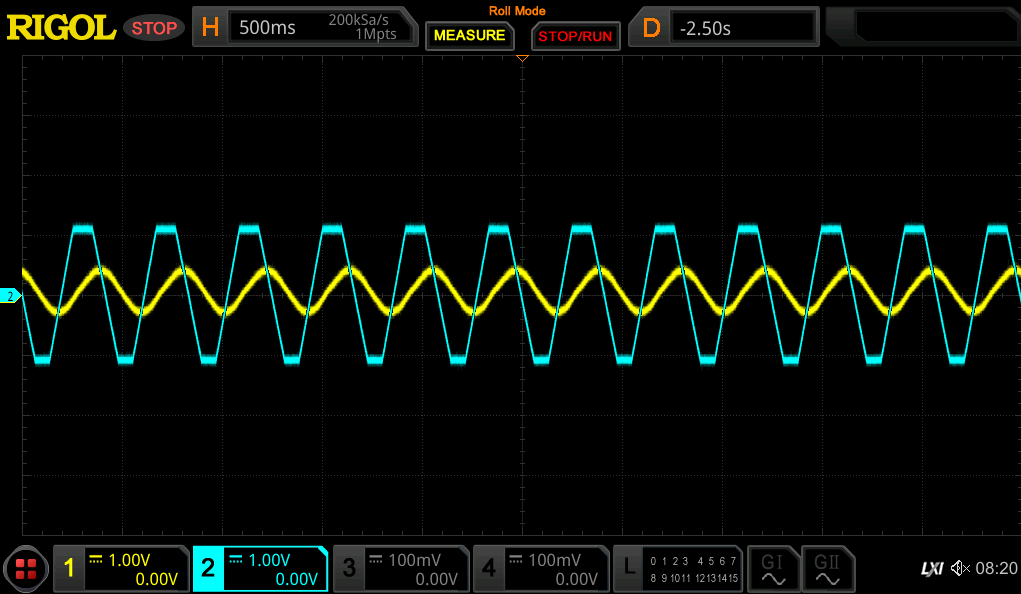
The output follows the input and wont exceed this. By playing around with the integration factor (making R60 a potentiometer), i get this:
![]()
BEAUTIFUL !
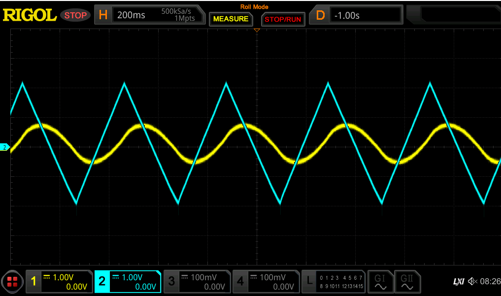
Also as a comparison, without the preshaping:
![]()
You can see, the sinewave is slightly skewed to the left side..... NOT BEAUTIFUL
-
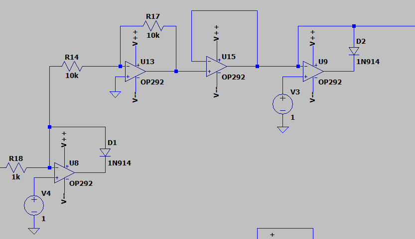
Preshaper stage
07/11/2025 at 06:31 • 0 commentsOk so a triangle is nice and all but we want a sine wave.
Just integrating and filtering the triangle gives us a pretty nasty distorted sine, so i added a preshaper stage whith makes the triangle trapezoidal.
![]()
So i cut off the top (here 1V limit, in real its controlled with a poti), flip it, cut off the other half, and done.
The result:
![]()
The original triangle in blue, the resulting trapezoid in yellow.
The 180° phaseshift is due to the flipping to cut off the top half. I didnt flip it back because it doesnt matter and i use quad-opamp IC´s ... so this part is neatly done with one IC.
-
Dual voltage supply from a single input
07/11/2025 at 05:22 • 0 commentsSo to make my life easier, i want to only use one power supply. Thus i need to generate the negative voltage.
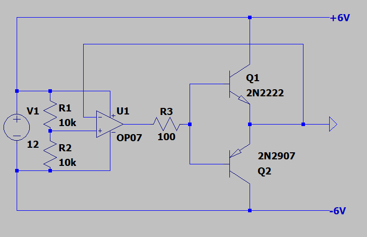
Get ready for some op-amp magic:
![]()
By setting the positive input to roughly 1/2 Vin and creating a feedback loop, i can use the output of the opamp as a "virtual ground".
MAGIC!
Adding a push pull transistor pair further increases the current capability of the output. However, this circuit is still pretty limited current wise but fine for our puroposes.
-> Just make sure to also use the virtual ground for any scope measurements
![]()
Adding this to my breadboard setup, it still works super fine
![]()
-
Upgrading the oscillator to a VCO
07/10/2025 at 11:24 • 0 commentsTo make it a voltage controlled oscillator (=VCO) we need the tweak it a bit.
As mentioned before, one possibilities to change the oscillators speed is to change the incoming voltage levels.
My idea is to split the squarewave into positive and negative, clip the maximum of both, and add them together at the end.
![]()
The negative part gets inverted after and before clipping. This way i can clip both halfs with just one control voltage.
![]()
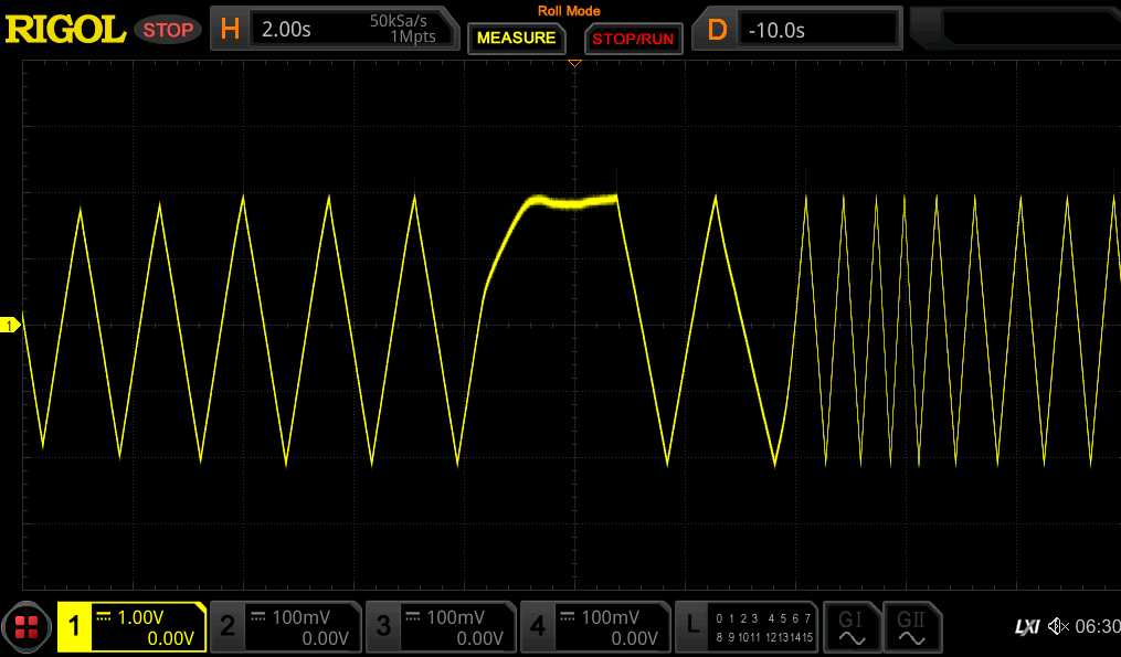
I built it up with some opamps and .....
![]()
It actually works!
Yellow is the triangle output and blue the control voltage.
The (analog) 1Hz sinewave generator
The most ridiculous, overengineered, stupid way to create a 1Hz sinewave using OP-amps ..... (and a timer)