Vipin M
-
Waypoint Navigation
08/01/2025 at 15:36 • 0 commentsIn robotics development, valuable capabilities often exist in the framework long before custom implementations become necessary.
Discovery Through Configuration Audit
While preparing to implement waypoint navigation on the Perceptor robot, I found that the functionality was already pre-configured in the existing
nav2_params.yamlfile. Thewaypoint_followernode was enabled and correctly parameterized from the initial Nav2 integration. No additional code or infrastructure changes were required.This highlights the completeness of the Nav2 stack—key features are often functional by default, requiring only proper invocation through existing interfaces.
RViz as a Control Surface for Waypoints
RViz's Nav2 plugin includes a visual interface for managing waypoint navigation without writing ROS action clients or manually specifying coordinates. The waypoint execution process is fully operable through GUI interaction:
-
Launch the standard Nav2 stack
-
Open RViz with appropriate Nav2 config
-
Set the initial pose using the "2D Pose Estimate" tool
-
Enable "Waypoint Mode" in the Nav2 panel
-
Click target waypoints on the map (clicks are sequentially ordered)
-
Click "Start Waypoint Following" to execute the route
RViz publishes waypoint goals via the
FollowWaypointsaction interface. Each waypoint is visualized on the map in real time.No code, YAML editing, or coordinate calculation is required.
Compatibility with Existing Navigation Features
Waypoint navigation inherits all runtime behavior defined by the motion planning and costmap layers:
-
Keepout Zones: The global planner automatically avoids keepout areas during path generation between waypoints. If a waypoint lies within a restricted zone, the planner reroutes to the nearest valid pose.
-
Speed Filter Zones: The robot dynamically adjusts velocity based on configured speed masks while traversing waypoints.
-
Dynamic Obstacle Avoidance: The local planner remains active, enabling real-time rerouting in response to moving obstacles.
This decoupling is possible because waypoint navigation operates at the task layer, while filters and collision avoidance operate at the path and motion planning layers.
Use Cases and Practical Deployment
Visual waypoint management enables multiple real-world applications without requiring custom software:
-
Security Patrols: Define patrol loops by placing sequential perimeter waypoints.
-
Inspection Routes: Navigate to sensors or hardware locations for regular inspection.
-
Cleaning Passes: Emulate room-based or grid-style cleaning patterns with precise coverage.
-
Demonstration Paths: Quickly generate visible motion plans for field demos and validation.
All of these can be configured ad hoc through the RViz interface in seconds.
Advanced Capabilities in Waypoint Follower
The
waypoint_followernode supports advanced configurations beyond RViz usage:-
Looped Missions: Enable automatic looping of waypoint sequences.
-
Failure Handling: Skip failed waypoints, retry with alternate paths, or abort on failure.
-
Waypoint Behaviors: Trigger plugin-based behaviors at specific waypoints (e.g., sensor polling, actuator control).
-
API Integration: Expose the ROS 2
FollowWaypointsaction interface for programmatic mission control and external system integration.
RViz usage is optional—programmatic access remains available via standard ROS 2 action clients.
Observations on Framework Design
The fact that
waypoint_followerwas pre-configured and operational illustrates a design strength of Nav2: core features are enabled by default, with sensible defaults and seamless subsystem integration.This architecture lowers the barrier to implementation by:
-
Minimizing manual configuration
-
Enabling discovery through GUI interfaces
-
Promoting modular task-level behaviors layered on top of reusable motion infrastructure
Future Work
Having verified waypoint navigation and integrated it into Perceptor's operational modes, the next logical extensions include:
-
Mission Scheduling: Time-based waypoint execution (e.g., hourly patrols)
-
Sensor-Driven Tasks: Conditional behaviors at waypoints triggered by sensor data
-
Fleet Coordination: Shared mission planning among multiple robots using synchronized waypoint strategies
-
Enhanced Autonomy: Integration with decision-making logic or symbolic planners
-
-
From SLAM to Smart Navigation
08/01/2025 at 06:44 • 0 commentsFollowing previous success fixing laser scan drift, I have upgraded the Perceptor robot from a basic SLAM platform into a modular autonomous navigation system with advanced features like keepout zones and variable speed control.
Overview
In the previous entry, I addressed laser scan drift on an RPLiDAR-equipped iRobot Create 2. After frame correction and sensor calibration, SLAM stability was achieved. This post focuses on the transition from mapping to fully autonomous navigation using ROS 2 and Nav2.
SLAM to Navigation with Nav2
Autonomous navigation requires multiple components beyond SLAM:
-
Localization: Determining robot pose on a known map
-
Path Planning: Computing viable paths to target poses
-
Obstacle Avoidance: Adapting to static and dynamic objects
-
Motion Control: Executing velocity commands safely
ROS 2’s Navigation Stack (Nav2) enables this functionality but demands hardware-aware configuration.
Replacing SLAM with AMCL
I replaced SLAM with AMCL (Adaptive Monte Carlo Localization) to localize using a static map. This allowed me to retain the same sensor suite while shifting to a particle filter approach:
amcl: ros__parameters: laser_model_type: "likelihood_field" max_particles: 2000 min_particles: 500 initial_pose: x: 0.0 y: 0.0 yaw: 0.0
Despite a minimal sensor stack, AMCL yielded reliable localization across varied test environments.
Modular Launch Design
To streamline development and debugging, I adopted a modular launch approach across four terminals:
# Terminal 1: Base and sensor drivers
ros2 launch perceptor launch_robot.launch.py

# Terminal 2: Localization
ros2 launch perceptor localization_launch.py map:=home.yaml

# Terminal 3: Nav2 stack
ros2 launch perceptor navigation_launch.py

# Terminal 4: Optional filters and extensions
ros2 launch perceptor keepout_extension.launch.py
Benefits:
-
Isolated debugging per component
-
Independent lifecycle control
-
Scalable architecture for feature integration
-
Faster iteration during development
Keepout Zones via Costmap Filters
To restrict the robot from entering specific regions, I implemented keepout zones using Nav2's costmap filters. Required components:
-
Binary mask image defining exclusion zones
-
Filter info server to define spatial metadata
-
Integration with global costmap
Correct alignment between map and mask was critical. Misalignment led to unintended path planning behavior.
keepout_filter:  plugin: "nav2_costmap_2d::KeepoutFilter"
enabled: True
filter_info_topic: "/costmap_filter_info"
Configuration Issue: Missing Publisher
Initial implementation failed due to the absence of a speed limit publisher:
ros2 topic info /speed_limit --verbose
# Publisher count: 0  <- No effect on speed
Adding the following parameter resolved the issue:
speed_filter: plugin: "nav2_costmap_2d::SpeedFilter" enabled: True filter_info_topic: "/speed_filter_info" speed_limit_topic: "/speed_limit"
Without this, the filter parses the mask but never communicates velocity limits to the controller.
Integration Challenges
Coordinate Frame Alignment
All masks and maps required:
-
Identical origins
-
Same resolution (0.05 m/pixel)
-
Cross-verification tools to ensure alignment
Simultaneous Filter Operation
Running multiple filters required:
-
Unique topic names
-
Independent node lifecycles
-
Distinct map servers per filter
Performance Optimization
On Raspberry Pi 5:
-
CPU usage was monitored during planning
-
Memory overhead increased with additional costmap layers
-
Modular design enabled disabling unused filters to conserve resources
Current Capabilities
Perceptor now supports:
-
Stable indoor localization (±5 cm)
-
Obstacle avoidance and path planning (planning time < 200 ms)
-
Keepout enforcement with high spatial precision
-
Speed-controlled navigation based on map zones
-
Modular launch for component-based deployment
Best Practices and Takeaways
-
Configuration Depth: Many critical parameters are buried in reference docs or only mentioned briefly.
-
Launch Modularity: Greatly improves debugging and experimentation.
-
Tooling: Developed utility scripts for verifying map alignment and topic health.
Roadmap
Planned enhancements:
-
Waypoint Follower: Multi-point missions and patrols
-
Dynamic Obstacles: Real-time costmap updates for moving objects
-
Fleet Support: Multi-robot coordination
-
Sensor Fusion: IMU and camera integration for robust localization
-
-
SLAM Debugging: When Perceptor's Laser Scans Drift from the Map
07/28/2025 at 15:35 • 0 commentsThe Problem: Laser Scan Drift
While running SLAM on my Create 2-based robot with an RPLiDAR, I noticed an odd issue. Initially, the map looked fine and the robot localized correctly, but over time, the laser scan visualization in RViz started drifting away from the map. The pink laser scan lines—meant to reflect real-world walls and obstacles—became increasingly misaligned. The map itself didn't distort, but the scan data no longer lined up, making it hard to trust the real-time sensor output.
The Cause: Coordinate Frame Misalignment
After some investigation, I found the issue was a coordinate frame mismatch. Specifically:
-
The LiDAR’s internal 0° direction was pointing backward, opposite to the robot’s forward direction.
-
ROS and SLAM algorithms expect the laser’s +X axis to face forward.
-
This mismatch introduced a 180° angular offset, which affected how odometry and scan data fused over time.
The SLAM system was trying to make sense of data coming in at the wrong orientation, which led to scan drift, even though mapping and localization initially appeared correct.
The Fix: Correcting the Laser Frame Orientation
To fix this, I modified the URDF to rotate the laser frame by 180° around the Z-axis. I added this transform to align the LiDAR’s forward direction with the robot’s:
<origin xyz="0 0 0.1" rpy="0 0 3.14159" />
This single change ensured that:
-
The laser’s 0° angle points in the robot’s forward direction.
-
SLAM receives properly oriented scan data.
-
TF transformations (map → odom → base_link → laser) stay consistent.
The Result: Solid, Aligned SLAM
After making the adjustment:
-
Laser scans in RViz stay aligned with the map.
-
Real-time obstacle data matches physical surroundings.
-
The robot can map reliably with minimal drift.
Current Status
Using SLAM Toolbox, I’m now able to generate accurate maps. I briefly tested AMCL by running Nav2 with the saved map published via the map server. Localization appears accurate, and the robot’s estimated position matches the environment. The next step is to test autonomous navigation using this setup.
-
-
Initial Challenges: When SLAM Goes Wrong
07/28/2025 at 02:36 • 0 commentsThe Symptoms
My SLAM system showed classic drift symptoms that pointed to deeper issues:
-
Laser Scans Moving with Robot: In RViz, the pink laser scan dots moved with the robot instead of remaining fixed in the map frame.
-
Frame Separation: I noticed three distinct coordinate origins — the robot, odometry frame, and map frame — all offset from each other.
-
Transform Extrapolation Errors: RViz logs were filled with timing-related errors.
-
Map Distortion: The map looked okay when stationary but warped during motion.
The Confusion
What confused me most: laser scans drifted during straight-line motion but partially realigned during rotation. Initially, I mistook this for working loop closure. But after deeper analysis, I realized loop closure is not functioning properly yet. The system is trying — but it isn’t successfully closing loops or correcting long-term drift.
🔍 Diagnostic Process: Systematic Debugging
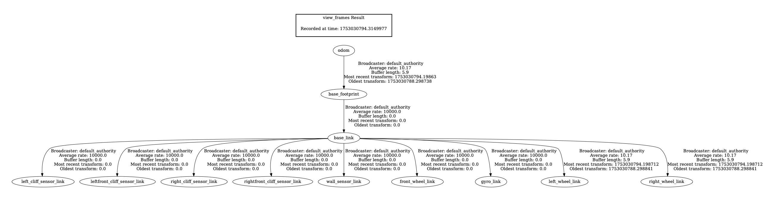
Step 1: Transform Tree Analysis
I inspected the transform tree:
-
Key Finding: The transform chain (
map → odom → base_footprint → base_link → laser) was structurally correct, but timestamps were often misaligned, causing extrapolation errors.# Check TF tree structure ros2 run tf2_tools view_frames # Monitor specific frame relationships ros2 run tf2_ros tf2_echo map odom ros2 run tf2_ros tf2_echo base_footprint base_link ros2 run tf2_ros tf2_echo base_link laser
Step 2: Topic Rate and Timestamp Validation
I measured the topic rates and confirmed mismatches between TF publishing and sensor data timestamps.
# Check component frequencies
ros2 topic hz /scan # Result: 7.5Hz (good)
ros2 topic hz /tf # Result: 70Hz (excellent) ros2 topic hz /map # Result: 0.2Hz (every 5 seconds)
ros2 topic hz /odom # Result: 10Hz (adequate)
Step 3: Odometry Accuracy Evaluation
To understand how much odometry might be contributing to drift, I tested it in isolation:
-
Commanded: 1.0m forward
-
Actual: 1.073m forward
-
Error: ~7.3% — surprisingly decent for a Create 2
# Linear accuracy test
echo "Starting position:"
ros2 topic echo /odom --once | grep -A3 "position:"

# Move exactly 1 meter forward
timeout 20s ros2 topic pub /cmd_vel_nav geometry_msgs/msg/Twist \
  "{linear: {x: 0.05, y: 0.0, z: 0.0}, angular: {x: 0.0, y: 0.0, z: 0.0}}" --rate 10

echo "Final position:"
ros2 topic echo /odom --once | grep -A3 "position:"
Step 4: SLAM Correction Attempt Monitoring
I tried to monitor how well SLAM was correcting drift over short tests:
-
Before Movement: [0.000, 0.000, -0.017]
-
After Movement: [-0.020, 0.023, -0.017]
-
The small correction suggests some adjustment, but not the kind of large-scale loop closure I expected.
# Monitor map-odom transform during movement
ros2 run tf2_ros tf2_echo map odom
🛠️ Partial Fixes and Improvements So Far
✅ Transform Timing Stabilized
I improved the startup order and transform publication frequency, which eliminated most extrapolation errors.
# Correct startup order
# Terminal 1: Start robot first, wait for full initialization
ros2 launch perceptor launch_robot.launch.py enable_camera:=false

# Terminal 2: Start SLAM after robot is ready
ros2 launch slam_toolbox online_async_launch.py \
  params_file:=/home/pi/Roomba/slam_dev_ws/src/perceptor/config/mapper_params_online_async.yaml \
  use_sim_time:=false

# Terminal 3: Start RViz last
ros2 run rviz2 rviz2 -d src/perceptor/config/map.rviz
✅ Removed Feedback Loop in Twist_Mux
I had incorrectly set both input and output of
twist_muxto/cmd_vel, creating an infinite feedback loop. Separating them fixed the phantom motion issue.# config/twist_mux.yaml - BEFORE (broken) navigation: topic: cmd_vel # ❌ Same as output - creates feedback loop! timeout: 0.5 priority: 10 # AFTER (fixed) navigation: topic: cmd_vel_nav # ✅ Separate input topic timeout: 0.5 priority: 10✅ Simplified Configuration Files
Merged redundant joystick configuration files for better maintainability.
# config/pro_controller.yaml - Consolidated Nintendo Pro Controller config
joy_teleop:
  ros__parameters:
    axis_linear:
      x: 1    # Left stick vertical
    scale_linear:
      x: 0.4  # Fast mode: 0.4 m/s, Slow mode: 0.2 m/s
    axis_angular:
      yaw: 0  # Left stick horizontal
    scale_angular:
      yaw: 2.4  # Fast mode: 2.4 rad/s, Slow mode: 1.2 rad/s
    enable_button: 3  # Y button deadman switch
    enable_turbo_button: -1
🛠️ Still Unresolved: Loop Closure
Despite these improvements, the SLAM drift continues to accumulate, and loop closure is not triggering as expected. Maps don’t realign reliably after revisiting known locations. Laser scans still exhibit visible drift over longer distances. Tried the following but did not help.
# config/mapper_params_online_async.yaml - Optimized for poor odometry
slam_toolbox:
  ros__parameters:
    # Faster transform publishing for better RViz sync
    transform_publish_period: 0.02  # Was: 0.05
    transform_timeout: 0.1          # Was: 0.2

    # More frequent map updates
    map_update_interval: 2.0        # Was: 5.0

    # Reduce odometry reliance, increase scan matching
    minimum_travel_distance: 0.05   # Was: 0.5
    minimum_travel_heading: 0.05    # Was: 0.5
    distance_variance_penalty: 0.1  # Was: 0.5
    angle_variance_penalty: 0.1     # Was: 1.0

    # Correct frame configuration
    base_frame: base_link           # Was: base_footprint
    max_laser_range: 12.0          # Match RPLidar A1M8 specs
⚠️ Key Takeaways (So Far)
1. Not All Drift Is a Bug — But This One Is
SLAM does allow small drift during straight-line motion, but in my case, the system isn’t correcting it later. Loop closure is either failing to trigger or not correcting the map correctly.
2. TF Synchronization Issues Were a Real Problem
Fixing transform timing helped reduce errors in RViz and made debugging easier — but didn’t fix the core SLAM issue.
3. Good Odometry Helps, But Isn’t Enough
Even with decent odometry (~7% error), the SLAM system needs successful loop closures to stay accurate over time.
🔄 Next Steps
-
Tune SLAM Parameters Further: I suspect
loop_closure_detection_frequency,transform_timeout, and other parameters may need to be better tuned for my platform. -
Enable SLAM Toolbox Debug Output: To confirm whether loop closure candidates are being rejected or missed entirely.
-
Visualize Pose Graph: I want to use tools like RViz or SLAM Toolbox’s pose graph visualizer to see whether loop closure edges are being added at all.
-
Add IMU or Fiducial Markers: If loop closure continues to fail, I may try sensor fusion (IMU) or use AprilTags for artificial loop closures.
💭 In Summary
I’ve addressed some foundational system-level bugs — transform timing, configuration loops, and odometry validation — but true loop closure remains unresolved. Until I see consistent corrections during revisited areas, I won’t consider SLAM working as intended.
This is still very much a work in progress, and I’ll continue refining parameters and adding tools to get to robust, drift-free mapping.
-
-
Upgrading to Raspberry Pi 5 and ROS 2 Jazzy
07/20/2025 at 17:56 • 0 commentsThe journey to transform a Roomba 650 into a fully autonomous SLAM robot continues with some significant hardware and software upgrades. This update covers the migration from Raspberry Pi 3 to Pi 5, the transition to ROS 2 Jazzy, power management challenges, and getting gamepad control working.
The Great Migration: Pi 3 to Pi 5
Initial Challenges with Pi 3
The original plan involved using a Raspberry Pi 3 with Ubuntu 22.04 Core and ROS 2 Humble. However, this setup proved problematic due to missing ROS components and the limitations of Ubuntu Core's snap-based package management. While Ubuntu Desktop isn't officially supported on Pi 3 due to its 1GB RAM limitation, the constant troubleshooting was becoming a distraction from the core SLAM development.
Future-Proofing with Pi 5
Given the project's eventual goals of heavy-duty image processing and AI integration, I decided to future-proof the system by upgrading to a Raspberry Pi 5. This decision came with its own cascade of changes:
- Pi 5 requires Ubuntu 24.04 (no 22.04 support)
- Ubuntu 24.04 ships with ROS 2 Jazzy (not Humble)
- Development machine also needed upgrading to maintain version consistency
The migration to Ubuntu 24.04 and ROS 2 Jazzy on both the Pi and development machine was necessary to ensure compatibility across the entire development pipeline.
Power Management: The Pi 5 Challenge
Current Limitations
The Pi 5's higher power requirements (up to 5A at 5V) created an immediate problem. The Roomba's serial port can only source 200mA before triggering its PTC resettable fuse. This meant the original power-over-serial approach was no longer viable.
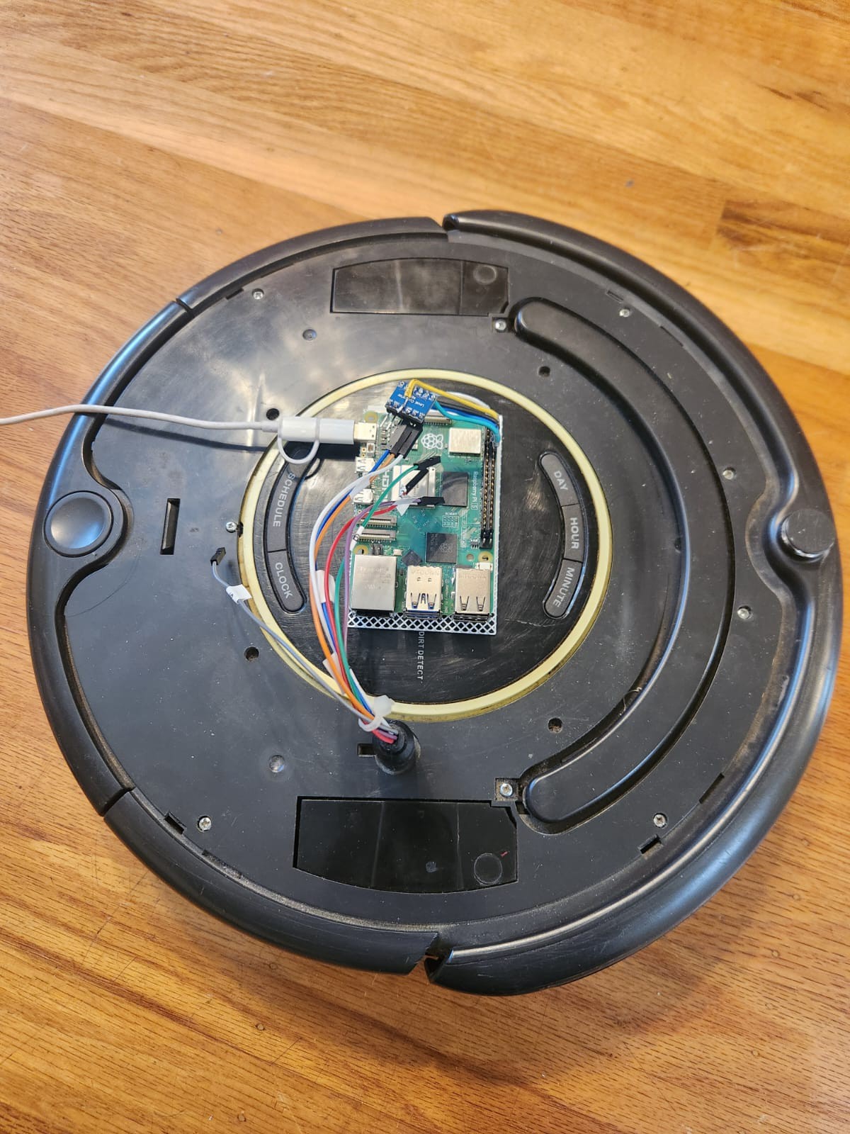
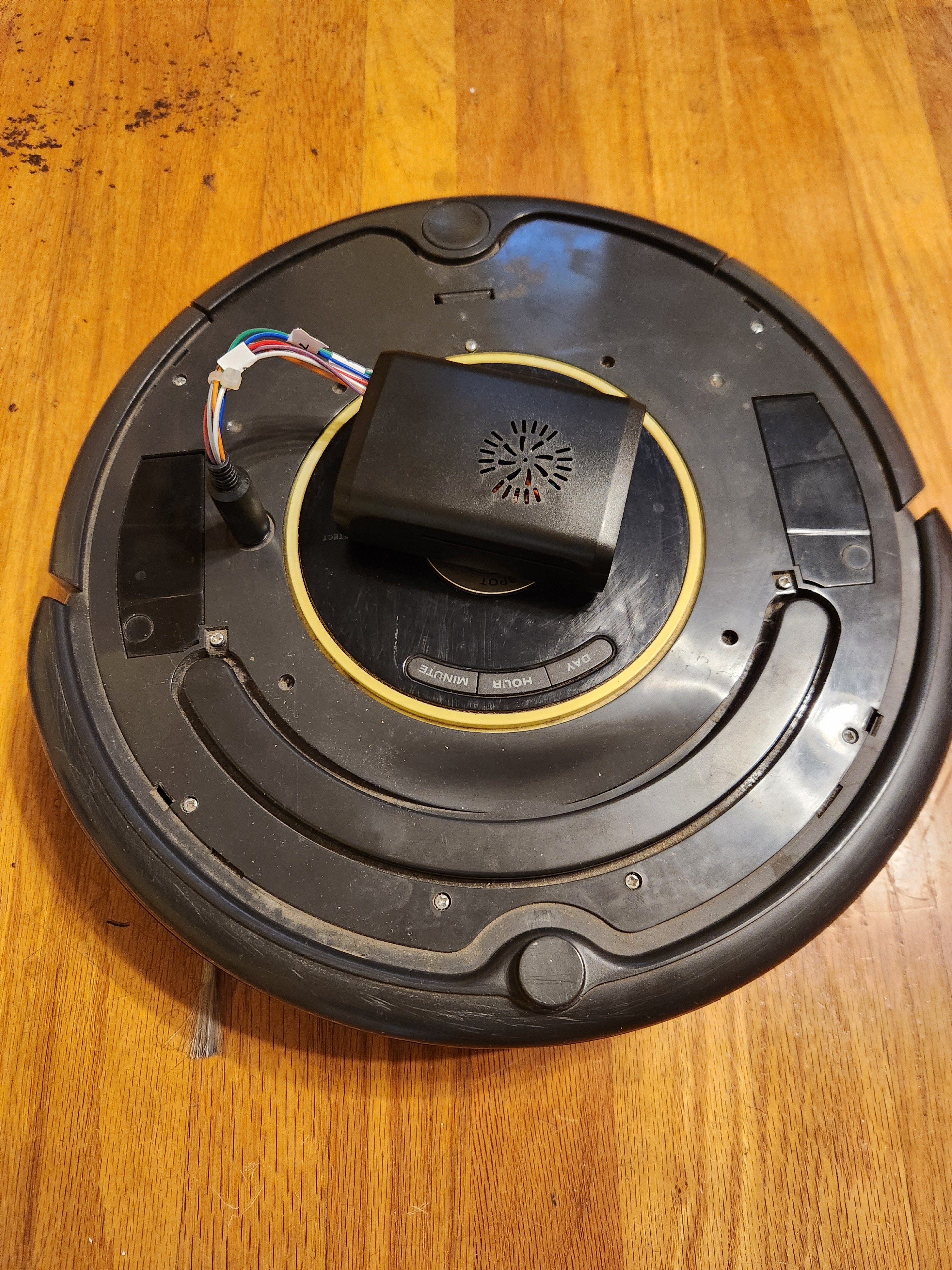
Hardware Modifications
The solution involved modifying the custom cable by removing the voltage regulator circuit. Now the Pi 5 runs on external power while maintaining serial communication with the Roomba. When externally powered, the Pi 5 actually sources 5V to the level shifter rather than sinking it.
![]()
Future Power Solutions
The current "tethered" approach is temporary. Future plans include:
- Tapping directly into the Roomba's battery pack
- Using a USB-C PD 3.0 compliant charging module
- Maintaining the 200mA limit on the serial interface
Until then, the Roomba sports a power "tail" for development work.
UART Configuration on Pi 5
Unlike previous Pi models, the Pi 5 doesn't have UART pins enabled by default. This required:
- Enable UART via raspi-config
- Add
dtparam=uart0to/boot/firmware/config.txt
These changes ensure the GPIO pins 14 (TX) and 15 (RX) function properly for serial communication.
ROS 2 Jazzy Integration
Installation and Verification
ROS 2 Jazzy was successfully installed on the Pi 5 and verified using the standard talker/listener demo. The
<span class="c-chat-codespan__content svelte-17rwp8y">create_robot</span>driver was then brought up, establishing bidirectional communication:- Robot control via
/cmd_veltopic - Sensor data publishing on various topics (
/odom,/scan,/battery, etc.)
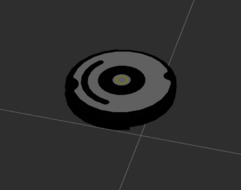
Teleoperation Success
The system now responds perfectly to
teleop_twist_keyboardcommands, with real-time visualization in RViz2 showing the robot model moving in sync with the physical Roomba.![]()
![]()
Gamepad Control Integration
Nintendo Pro Controller Setup
A Nintendo Switch Pro Controller was successfully paired via Bluetooth. The system logs show proper recognition:
nintendo 0005:057E:2009.0008: hidraw0: BLUETOOTH HID v80.01 Gamepad [Pro Controller]
input: Pro Controller as /devices/platform/soc/.../input/input23ROS 2 Joy Integration
The ROS 2
joy_nodesuccessfully interfaces with the Pro Controller:ros2 run joy joy_node
[INFO] [joy_node]: Opened joystick: Pro Controller. deadzone: 0.050000Gamepad Control Success
The existing joy_teleop.launch file from the create_robot package worked perfectly with the Nintendo Pro Controller. Using the pro_controller.yaml configuration file, the system launched successfully:
ros2 launch create_bringup joy_teleop.launch joy_config:=pro_controller
![]()
The Roomba now responds perfectly to gamepad input, providing intuitive wireless control with analog stick precision for both linear and angular movement. The Pro Controller's ergonomic design makes extended teleoperation sessions much more comfortable than keyboard control.
System Architecture
The current system architecture includes:
- Raspberry Pi 5 running ROS 2 Jazzy
- create_robot driver for Roomba communication
- RPLiDAR A1M8 for laser scanning
- Nintendo Pro Controller for wireless teleoperation
- RViz2 visualization on development machine
Next Steps
With the hardware platform stabilized, the immediate next steps are:
- LiDAR bringup
- SLAM Toolbox integration to fuse odometry and laser scan data
- Live mapping and map visualization
- Autonomous navigation using the ROS 2 Navigation Stack
The foundation is now solid with a more powerful Pi 5, stable ROS 2 Jazzy environment, and multiple control interfaces. The next update will focus on bringing the SLAM stack online and generating the first autonomous maps.
-
Of Bots, Beeps, and Bumps: Prepping Roomba for SLAM
07/18/2025 at 14:26 • 0 commentsThe journey to turning a Roomba 650 into a ROS 2-enabled SLAM and navigation robot has been eventful. Although the SLAM stack isn't powered up yet, much groundwork has been completed to reach that point. This update documents the process, decisions made along the way, and a glimpse of what’s next.
Hardware Interface and Serial Communication
The project began with a deep dive into the iRobot Create Open Interface (OI) specification to understand the Roomba’s serial communication requirements. From there, the Roomba's 7-pin mini-DIN port was mapped to identify the relevant pins for TX, RX, and power.
It became clear that the Roomba's serial interface operated at 5V logic, while the Raspberry Pi's UART is 3.3V tolerant. To bridge this, I built a custom cable incorporating a level shifter. A DC-DC voltage regulator was also added to power the Raspberry Pi directly from the Roomba's onboard battery.
The initial attempt to communicate between the Pi and Roomba was unsuccessful. To debug, I replaced Roomba with an Arduino Uno, attempting a loopback test through the Arduino itself, but that too failed. I then created a local loopback on the Pi (jump TX to RX), which succeeded and reassured me that the Pi GPIOs were not fried. Returning to the Pi, the correct serial port abstraction was identified—
/dev/ttyAMA0or/dev/serial0—which had been part of the earlier confusion.This progress made it worthwhile to improve the hardware connections, so a custom header was fabricated for the Raspberry Pi’s 40-pin connector to secure the wiring and facilitate swapping Pis without rewiring. With renewed confidence, I returned to the Pi to successfully establish communication with the Roomba.
![]()
Validating Control and Sensor Feedback
With the hardware connection sorted, the next step was to develop basic Python scripts to:
-
Start the Roomba’s OI
-
Drive forward, reverse, and rotate
-
Query sensor data including bump sensors, battery status, and distance traveled
This formed the first real confirmation that the Roomba was responding properly to commands issued from the Raspberry Pi.
Moving to ROS 2: create_robot Package
Next, I turned to the create_robot ROS 2 package from AutonomyLab. After cloning and building the package on the Raspberry Pi, the create_driver was launched:
ros2 launch create_bringup create_driver.launch.py serial:=/dev/serial0 baud:=115200
Once running, several topics became available:
-
/odomfor odometry -
/cmd_velfor velocity commands -
/battery/voltage -
/bumper -
/wheel_drop -
/cliff -
/light_bumper -
/ir_opcode -
/dock -
/buttons
Exploring Teleoperation
To control the robot, I started with
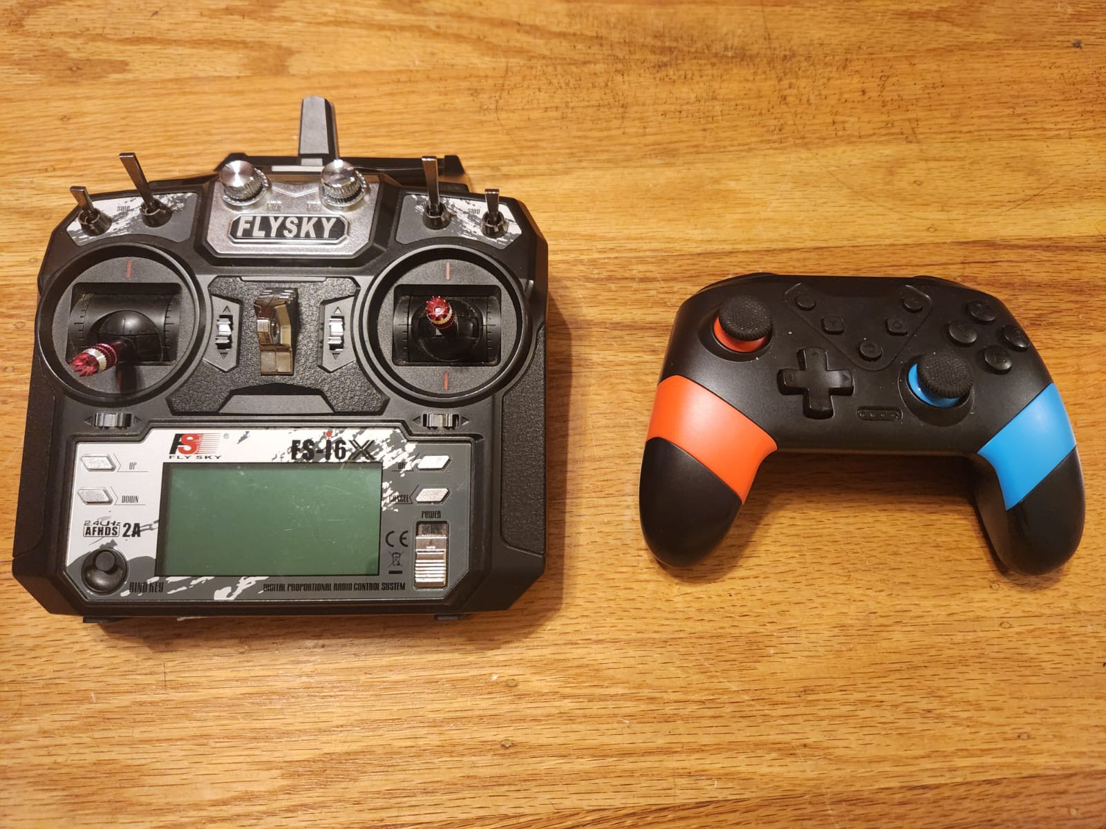
teleop_twist_keyboard, a ROS 2 package that allows controlling via a keyboard. While exploring options for more intuitive control, I discovered two existing controllers at home: a Flysky RC transmitter used for drones and a Nintendo Switch controller. The latter was stolen from my son's stash and the former is something that both of use when we go out for flying drones and foamies.![]()
The Switch controller was an easy pick because it could pair directly to the Pi via Bluetooth. The Flysky controller would have required an additional receiver, although I learned that with the
inputattachtool, it's now possible to integrate such RC transmitters with Linux as joystick devices. This integration isn't complete yet but is on the list for a future blog post.Setting Up RPLiDAR with ROS 2
With Roomba control and telemetry operational, the next focus was on integrating the RPLiDAR A1M8. This was first brought up on a desktop Linux machine running Ubuntu 22.04 and ROS 2 Humble, to simplify testing.
Once verified, the setup was migrated to the Raspberry Pi. The
rplidar_nodepublished data on the/scantopic, confirming that the LIDAR was functioning.A split architecture was then tested:
-
The Pi handled the LIDAR and published
/scan -
A host computer ran RViz2 for visualization via ROS 2 networking
![]()
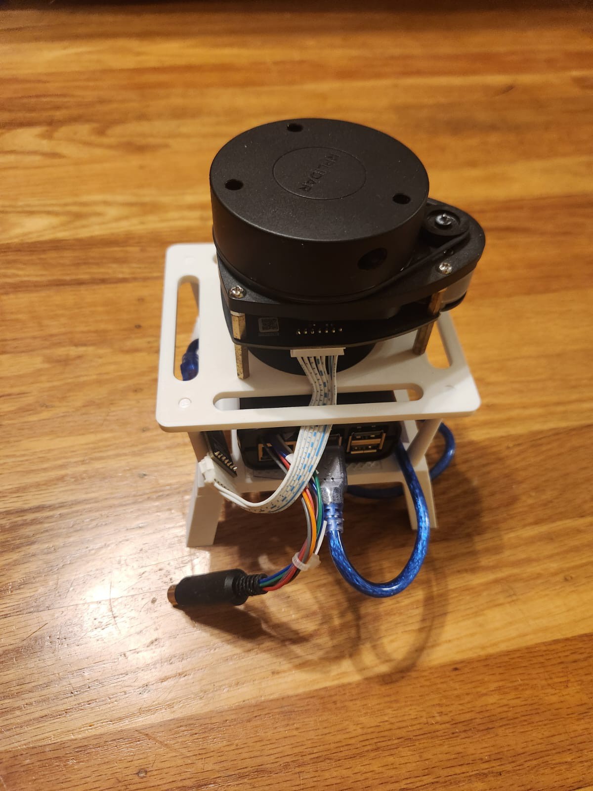
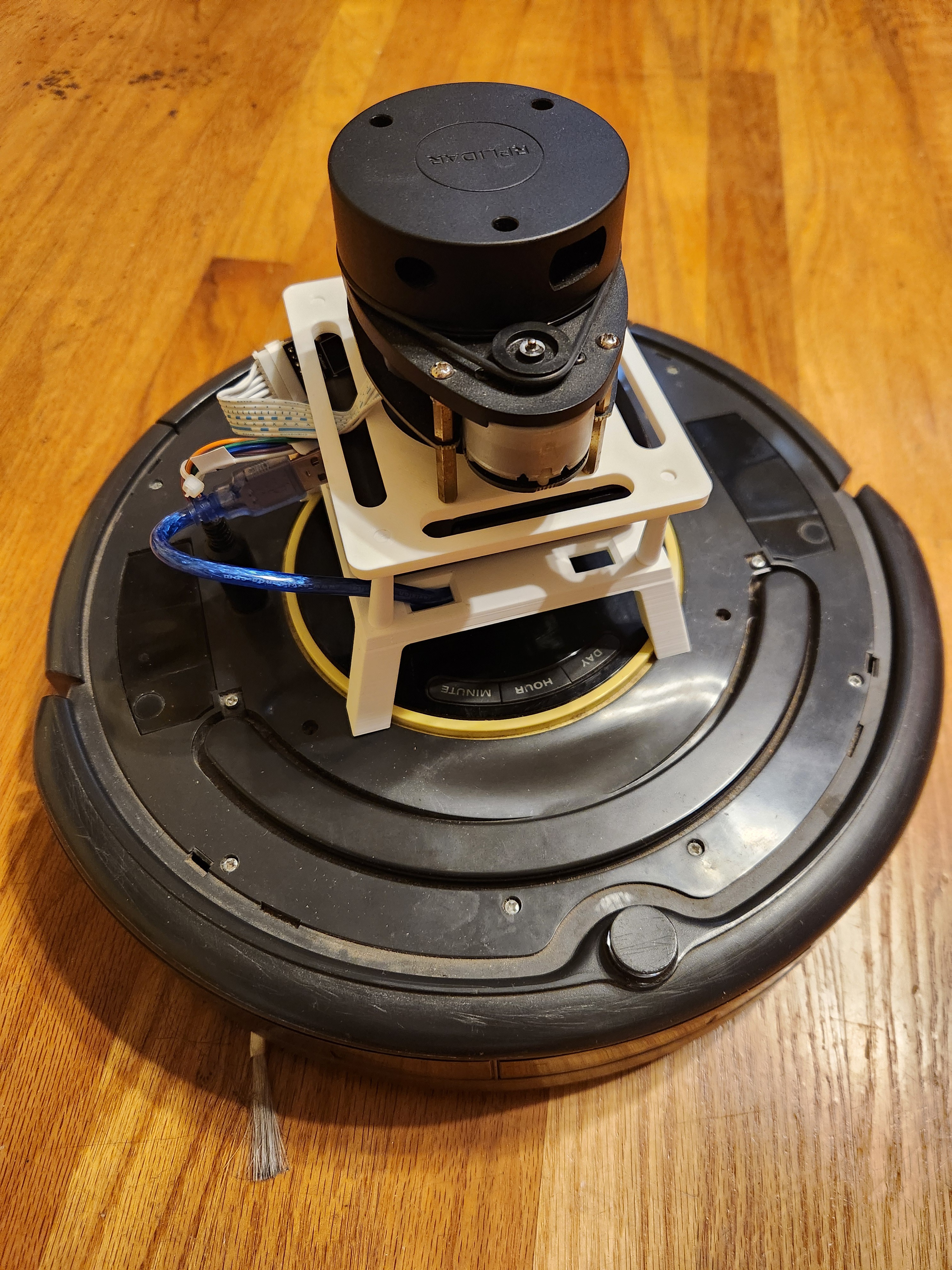
To properly mount the RPLiDAR on the Roomba, a 3D printed stand was designed and fabricated, which also housed the Raspberry Pi. The stand ensures a stable platform for the LIDAR and keeps wiring neat.
![]()
Current Status and Next Steps
Currently, the system comprises:
-
Roomba 650 with ROS 2 create_robot driver providing odometry
-
RPLiDAR A1M8 publishing laser scans
-
Manual teleoperation via keyboard
-
Visualization via RViz2
Next:
-
SLAM Toolbox integration to fuse
/scanand/odomand begin live map generation -
Visualization of the map alongside live scans and odometry
-
Eventually, integrate the ROS 2 Navigation Stack to enable goal-based autonomous navigation with dynamic obstacle avoidance
The pieces are in place; the next milestone is to bring them together under SLAM and start mapping the environment.
-
Perceptor - ROS2 Perception, Planning, Control
Modified Roomba with ROS2, LIDAR, and odometry running SLAM Toolbox for real-time mapping and navigation