I needed a compact and affordable way to measure very low resistances — so I built my own Micro-Ohmmeter. Starting from an open-source design, I gradually refined the electronics, mechanics, and calibration process to create a reliable, calibrated USB micro-ohmmeter. This project traces the journey from a basic DIY prototype to a finished, small-scale production-ready instrument.
After a few teasers, here’s the first fully functional version of my USB micro-ohmmeter.
Originally designed to test contact resistances in EV charging connectors, it’s now proving to be a precise and repeatable measurement tool for shunts, cables, and low-resistance connectors of all kinds.
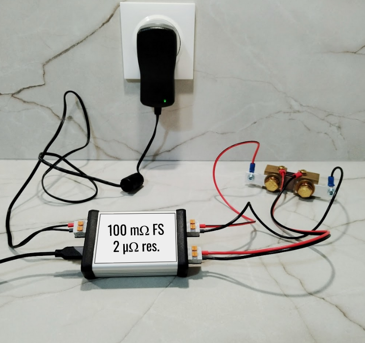
Photo of the prototype measuring a precision shunt (100 µΩ, 0.25%).
Key Specs
Measurement range: 0–100 mΩ (more to be tested)
Resolution: < 2 µΩ
Calibrated: Using precision resistors (100 µΩ, 1 mΩ, 10 mΩ)
Interface: USB-C with SCPI command set
The first measurement results are even better than expected — especially in terms of stability and effective resolution. For example, the ADC output shows about 88 counts when measuring a 100 µΩ shunt, which translates to an estimated resolution of ~1.14 µΩ.
Looking for Early Testers
I’m now looking for early testers interested in trying out this first version. If you work with low-resistance measurements and would like to give feedback on performance, usability, or possible improvements, please leave a comment or send me a message.
Your input will directly shape the next revision — which I plan to release later on Tindie.
What’s Next
In the next project log, I’ll run a stability analysis and share some thoughts on calibration methods for milliohm measurements.
Before designing my own precision micro-ohmmeter, I started by studying an excellent open-source project by Dennis Vollrath, published in Servo Magazine:
It’s a compact, well-thought-out DIY design with solid explanations — a perfect starting point for anyone exploring low-resistance measurements.
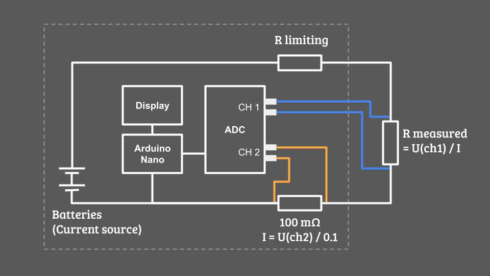
Simplified schematic of Dennis Vollrath’s design
What Makes Dennis’ Design Great
This project achieves surprisingly high performance for something you can build at home thank's to:
High test current — around 1.2 A
18-bit ADC ENoB ! (17 bits in unipolar mode)
Programmable differential amplifier with gain up to ×8 (in the ADC)
That translates into an estimated measurement resolution of:
Resolution = ADC voltage step / Current = (0.256 / 2^17) / 1.2 = 1.6 µOhm
For a device you can build for under €50, that’s remarkably good — especially with such a short BOM and a straightforward assembly.
Why I Had to Go Further
While Dennis’s design is excellent for hobbyists, my goal was to build something industrial-grade for integration into automated test benches. That required several key changes:
1. Professional Hardware
I redesigned the PCB to meet professional manufacturing standards — compact, robust, and ready to fit inside a proper enclosure with DIN rail mounting and standard connectors.
2. Power Supply Upgrade
The original design used batteries and a 5 Ω resistor to limit the current (Power loss = R*I² = 7,2 W in heat). My version had to work directly from the client’s 24 V DC supply, so I redesigned the power stage to efficiently deliver a stable, high test current. I also added circuitry to pulse the current only during measurements to avoid unnecessary heating.
3. USB-Only Interface
Since the device is part of an automated test bench, it doesn’t need a screen. I switched to a USB-only interface and rewrote the firmware accordingly to communicate directly with the client’s software.
4. Improved Analog Front-End
I added analog filtering on the ADC inputs and carefully optimized the PCB layout to minimize crosstalk and noise pickup — critical when you’re measuring signals in the microvolt range.
5. Calibration for Accuracy
Finally, I wanted each unit to be factory-calibrated against precision reference resistors to guarantee performance and reproducibility. I’ll share more about the calibration process in an upcoming log.
What’s Next
Dennis Vollrath’s project was a fantastic foundation, and my version takes the concept further — from a DIY project to a precision lab instrument.
In the next log, I’ll unveil my custom micro-ohmmeter design — optimized for accuracy, reliability, and industrial integration.
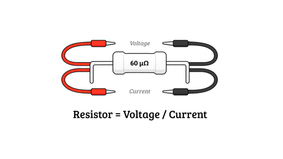
Measuring small resistances value isn’t new to most engineers — but once you get down to the milli-ohm or micro-ohm range, small details start to dominate. Wiring and connectors can add more resistance than the part itself. Contact resistance can change between measurements. High test currents cause self-heating, altering the value you’re trying to capture. And even tiny temperature differences between metals can generate microvolts that mask your real signal.
This whole project started with a phone call from a friend who designs custom industrial machines:
- Hey Dorian, I need to measure how the electrical resistance of automotive connectors changes as they get mated and unmated thousands of times. Is that something easy to do?
- Well… that depends on what resistance values we’re talking about.
- Around 60 micro-ohms.
- And what’s your budget?
- Under €1000 ... for the whole electronics part of the test bench... and everything has to fit in something the size of a shoebox.
At that point, I couldn’t help but laugh.
When I started looking into it, I realized I couldn’t find any instrument that could:
Resolve a few micro-ohms reliably,
Connect to a PC over USB,
Be compact and robust enough for industrial use,
And still cost under €500 (most commercial units are well above €1000).
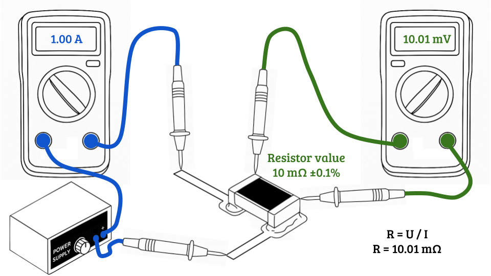
The closest solution I found was to cobble something together using a programmable lab power supply and a bench multimeter in a 4-wire setup, all controlled by a PC.
With decent Siglent gear that would have cost around:
SDM3045X 4½-digit multimeter – €369 (excl. VAT)
SPD1168X programmable power supply – €229 (excl. VAT)
So about €600 per measurement channel, and that’s just for the instruments — not exactly compact or budget-friendly.
And that’s when I decided to build my own tool.
In the next logs, I’ll dive into why measuring such low resistances is tricky, and show the open‑source design that kick‑started this project.